1
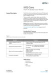
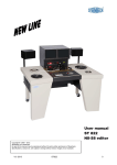
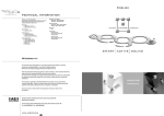
Owners Manual
EXTREME 5
EXTREME 8
1. Introduction
Thank you for purchasing this Acoustic Energy product. As a valued customer
we would like to keep you up to date with all news and events including new
2. Handling
products, exhibitions and exclusive promotions. To enable us to communicate
these exciting developments please go to our website - www.acoustic-energy.
co.uk - and complete the ownership registration form.
Extreme Series speakers are precision engineered
products that can be damaged by inappropriate
handling. If the speakers’ perforated grilles are
Perhaps more than any other audio product, speakers are sensitive to
installation so please take a little time to read this manual and to follow, as far
as practical, the guidelines it contains. Careful installation will help ensure that
removed take care not to touch any of the drivers.
Damage to a driver will at best degrade performance
and at worst result in complete failure.
your Extreme Series speakers perform optimally. Should you have any questions
not covered here we are happy to try and answer them either by telephone or
email. Contact information can be found in Section 11.
The enclosure surfaces should also be handled
sympathetically. Any cleaning should only require a
soft cloth, slightly dampened if necessary. Be wary of
This manual covers the Extreme 5 and Extreme 8. Following the introduction, it
using any polishes or solvent based cleaning agents.
is divided into sections covering handling, installation, positioning, mounting,
connection, amplifiers, listening, specifications, warranty and contact
The packaging should be retained for future use.
information. We recommend that you read at least the first six of these sections
carefully before installing and using your speakers.
3. Installation
Extreme Series speakers are intended to be mounted either vertically or
to any suitably sound structure.
Wall fittings (Rawlplugs, etc..) and screws are not included but should be chosen
appropriately for the type and condition of the structure the brackets are to be
attached to. Extreme Series speakers are heavy and you must be sure that the
structure and fittings chosen are able to support their weight. If you have any
concerns over the suitability of the structure, or doubt in your ability to fix the
brackets securely, you should seek professional advice and help.
Extreme Series speakers are “weather-proof”, “splash-proof” and suitable for use in
outdoor, damp, dusty or humid applications. They can also be installed and used
in environments that are subject to long-term ambient temperatures between 5°C
and 35°C. They are not suitable for installation where they will be continually in
contact with water.
Extreme Series enclosures and grilles can be painted to match interior design
schemes using domestic matt emulsion paint. Take grate care when painting grilles
that neither the driver units become contaminated with paint, nor that a significant
number of the grille perforations become blocked.
Neutrik® Speakon® input sockets only are fitted to Extreme Series speakers. An
appropriate Speakon plug is included with each speaker.
Page Neutrik® and the names of Neutrik® products referenced herein are either trademarks and/or service marks of Neutrik®.
horizontally using the supplied mounting brackets. The brackets can be attached
4. Positioning
The location of speakers within a listening environment
is likely to have more influence over their subjective
performance than any other aspect of installation. It is
worth spending some time considering both the finer
Stereo and Home Theatre Positioning
If a pair of speakers is to be used in a conventional stereo audio system or for the
front channels in a home theatre system they should be positioned approximately
as follows:
points of speaker location, as well as the larger scale
issues of room and speaker layout.
If you are already familiar with the acoustic
characteristics of the listening environment, and the
way speakers perform in it, you may already have a
•
At least 1.0 metre from side walls.
•
Between 2.5 and 3.5 metres apart.
•
Clear of corners.
•
Angled inward towards the listening position.
•
At, or slightly above, listening head-height.
good feel for where to position the speakers. However,
installing any new audio component provides a good
opportunity to review an existing set-up and perhaps
If a speaker is to be used for the centre channel in a home theatre system it should
be positioned approximately as follows:
make improvements.
•
Extreme Series speakers are not magnetically shielded
If two or more speakers are to be used for the surround channels in a home theatre
and should not be positioned in close proximity to
system they should be positioned approximately as follows:
magnetically sensitive equipment and media.
Directly above or below the display screen.
•
Generally in-line with or behind the listening position.
•
At least 0.5m above listening head height.
Diagram One illustrates general home-theatre speaker positioning.
Don’t worry if, thanks to the architecture or layout of your room, it is not practical
to follow each requirement exactly. The most important thing is to consider the
different options that are practical and identify the one that is likely to work best.
Utility Speaker Positioning
If Extreme Series speakers are to be used as multiple “utility” speakers in an
Diagram One
environment where the intention is to provide background music and/or public
address announcements they should be equally
distributed throughout the space and mounted
Centre
above head height. Mono audio is usually preferable
Right
Front
Left
Front
in utility applications but if only stereo is available
multiple speakers should be connected alternately to
the left and right channels.
In choosing locations for the speakers consider the
Sub-woofer
“coverage” required with respect to the likely listener
positions. Try and ensure that coverage is even and
that as listeners move around the environment their
distance to the nearest speaker remains relatively
Left
Surround
Alternative or
Extra Left
Surround
Viewing/listening position
Right
Surround
constant.
Alternative or
Extra Right
Surround
Page 5. Mounting Brackets
With speaker mounting locations selected, the Mounting Brackets can be attached
Once a bracket is securely fixed, attach the speaker by
to the mounting surface or structure. Diagram Two illustrates the bracket, speaker
offering it up to the bracket and inserting the threaded
and associated components.
section of each Attachment Knob in turn through the
Use the bracket itself as a template to mark the mounting hole positions employing
a spirit-level to ensure the bracket is level. The mounting holes are provided with
key-hole slots to simplify attachment. At least two screws must be used to attach
each bracket.
bracket and into the threaded holes in the speaker.
Tighten the Attachment Knobs while holding the
speaker at the desired mounting angle.
The speaker cable can either be threaded through the
Fittings (Rawlplugs, etc.) and screws are not included with the bracket but should
be chosen appropriately for the type and condition the of structure the brackets
are to be attached to. Extreme Series speakers are heavy and you must be sure
that the structure and fittings chosen are able to support their weight. If you have
any concerns over the suitability of the structure, or doubt in your ability to fix the
elongated hole in the centre of the Mounting Bracket
(before the bracket is attached) or left unattached to
the bracket. If the cable is to be threaded through the
Mounting Bracket make sure that there is enough
cable left free to enable easy attachment of the
Speakon plug and also that the cable is not trapped
brackets securely, you should seek professional advice and help.
behind the bracket when the mounting screws are
tightened.
Connecting the Speakon plugs and speakers is
Diagram Two
described in the following section.
Upper
Attachment
Knob
Mounting
Bracket
Lower
Attachment
Knob
Page 6. Connecting
Extreme Series speakers are fitted with Neutrik
Speakon connection sockets. An appropriate Speakon
Diagram Three
plug is included in each pack. Speakon sockets and
plugs provide a reliable, secure, and potentially
Connect
Positive
weather-proof connection.
Either 2-pole (Part No. NL2FC) or 4-pole (Part No.
NL4FC) plugs may be used. The supplied plug is a 2pole type. 4-pole Speakon plugs can additionally be
fitted with a weather-proof rubber sleeve (Part No.
Plug Body
Connect
Negative
Clamp Ring
Rear Housing
BSL-WR).
Speakon plugs and accessories are widely available
from audio and electronic component distributors and
retailers.
Diagram Three illustrates the assembly and connection
of a 2-pole Speakon plug. Remember to thread
the cable through the Rear Housing and Clamp
Ring before connecting it to the terminals. Strip
approximately 6mm of bare wire and connect to the
screw terminals within the Speakon. If using 4-pole
Speakon plugs use the terminals labelled +1 and -1.
Take care not to connect the negative and positive
terminals together and “short-circuit” the amplifier.
Make connections with the amplifier switched off. Once
To connect the speakers simply push the Speakon plug into the socket and twist
the plug clock-wise to lock. Twist counter-clockwise and pull to disconnect.
Connection Polarity.
It is important to ensure that each speaker is connected with the same polarity.
Positive speaker terminals should always be connected back to amplifier positive
terminals, and negative speaker terminals connected back to amplifier negative
terminals. Performance will be degraded if connections are made with incorrect
polarity.
Cable Choice.
the cable is connected to the terminals, the plug can be
Choice of cable type will be influenced by the application intended for your
reassembled. The Clamp Ring secures the cable as the
Extreme Series speakers and the characteristics of other components in your
Rear Housing is tightened.
system. Your dealer or distributor will be able to advise. There are however some
simple guidelines to consider:
•The external cable diameters compatible with Speakon plugs are as follows:
NL2FC (2-pole): 4mm - 10mm, NL4FC (4-pole) 5mm - 11mm (white Clamp
Ring), NL4FC (4 pole) 9.5mm - 15mm (black Clamp Ring).
•Cable runs to each speaker should be kept as short as possible.
•Short cable runs are especially important if the cable is of relatively small
cross-sectional-area.
•If the cable is advertised as “directional” care should be taken to ensure that
its orientation is as recommended.
Page 7. Amplifiers
Extreme Series speakers offer relatively high sensitivity and do not require
generously rated power amplifiers for adequate volume levels to be achieved in
8. Listening
typical listening environments. They also offer a relatively easy load to the amplifier
and do not make unusually heavy demands on its power delivery.
No overload protection systems are fitted to Extreme Series speakers so it is
possible to cause damage through over-driving. Such damage can occur whatever
the power rating of the amplifier and is not covered by any warranty. If ever the
sound at high volumes becomes distorted your speakers are at risk of damage. In
such circumstances the volume must be reduced.
It is wise before listening to your speakers to make one
final check of the cables and connections. If all appears
well begin listening at a relatively low level to confirm
that the system is operating as expected. Only increase
the volume if you are happy with the sound at low
levels. If you are unhappy, turn the system off and recheck all the cables and connections.
Extreme Series speakers may take a little time to “runin”, and similarly the system will also perhaps take
some time to reach normal operating temperatures. It
is unwise therefore to make rapid judgements about
the performance of the speakers. Your ears too will take
some time to adjust to the new sound, so revisiting the
system set-up, speaker positioning especially, is best
left for a few days.
9. Specifications
Model:
Extreme 5
Extreme 8
Type: 2-way, closed-box loaded. 2-way, closed-box loaded.
LF/MF Driver: 110mm pressed alloy cone.
160mm pressed alloy cone.
HF Driver:
25mm Dome.
25mm Dome.
Filter Network: 3rd order at 3.0kHz.
3rd order 3.0kHz
Cabinet:
Reinforced Structural Polymer.
Reinforced Structural Polymer.
Frequency Response:
70Hz to 18kHz ±3dB 55Hz to 18kHz ±3dB
Frequency Range:
60Hz to 20kHz @ -6dB 45Hz to 20kHz @ -6dB
Power Handling:
125W peak programme
150W peak programme
Amplifier Compatibility: 25 - 125 Watts into 8 Ohms 25 - 150 Watts into 8 Ohms
Nominal Impedance: 8 Ohms
8 Ohms
Sensitivity:
89dB for 1 Watt at 1 metre
90dB for 1 Watt at 1 metre
Ambient Temperature Range:
5°C to 35°C
5°C to 35°C
Enclosure Sealing Specification:
IP54
IP54
Dimensions (H x W x D):
260 x 160 x 180mm 390 x 260 x 260mm
Weight (including bracket):
3.0kg (single, unpacked)
7.0kg (single, unpacked)
Finish:
Black or white
Black or white
Acoustic Energy reserves the right to modify product specifications.
Page 10. Warranty
Your Acoustic Energy speakers are guaranteed
against original defects in materials, manufacture and
workmanship for one year from the date of purchase.
Name:
Address:
Under this warranty Acoustic Energy agrees to repair
any defect or, at the company’s discretion, replace
the faulty component(s) without charge for parts or
labour. This warranty does not imply any acceptance
by Acoustic Energy or its agents for consequential loss
Dealer:
Purchase Date:
Serial Numbers:
or damage and specifically excludes fair wear and tear,
accident, misuse or unauthorised modification.
This warranty is applicable in the United Kingdom only
and does not in any way limit the customer’s legal
rights. If you have reason to claim under the warranty
please contact your dealer in the first instance
11. Contact
Claims and enquiries under the warranty for Acoustic
Energy products purchased outside the UK should be
Acoustic Energy Limited
addressed to the local importers or distributors.
16 Bridge Road
Please retain all original packaging materials for
Cirencester
possible future use. We suggest that you complete
Gloucestershire GL7 1NJ
details of purchase now and keep this information in a
UK
safe place for future reference.
Tel: +44 (0)1285 654432 (Sales)
+44 (0)1285 656890 (Technical)
Fax: +44 (0)1285 654430
Email:
[email protected]
Web: www.acoustic-energy.co.uk
Products that display the crossed-out wheeled bin logo
cannot be disposed of as domestic waste but must
be taken to a facility capable of re-cycling them and
appropriately handling any waste by-products. Contact
your local authority for details of the nearest such facility.
Page EXTREME 5
EXTREME 8
Acoustic Energy Limited, 16 Bridge Road, Cirencester, Gloucestershire GL7 1NJ.
Tel: +44 (0)1285 654432 (Sales), +44 (0)1285 656890 (Technical). Fax: +44 (0)1285 654430
Email: [email protected]
Web: www.acoustic-energy.co.uk
Manual Part No. MA2801