1
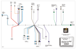
Evo860 User Manual
Overview
The Evo860 system comprises a base unit housed in a robust, water-resistant housing to which you can
connect up to four antennae (eight on a Mk3). The type of antennae depends on the kind of event that you
are timing; running events generally use sectional floor mats while cycling and multisport events like triathlon and duathlon would use tripod mounted units spaced down the side of a road or track. Antennae can
be mixed so it’s perfectly possible to have two run mats and two cycle units controlled by a single box configured as two separate timing points.
The controller is powered by internal batteries with the option of having an external battery connected for
events lasting over 8 hours or to be connected to a mains power supply for virtually indefinite use.
There have been three iterations of the Evo860 design so far:
The Mk1 is a four-port unit with no WiFi built in and looks like this.
Evo860 User Manual
Page 1
Rev: 23-Apr-13
Race Timing
Systems
Evo860 User Manual
The Mk2 unit is housed in the same Peli case but has a very different main panel layout. The Mk2 uses a
new controller PC which adds additional functionality with dual wired network connections allowing the
internal reader to be isolated from the main network and comes with WiFi as a connection option. The
basic Mk2 is a four-port unit like the Mk1 – the two variants use the same internal tag reader.
Evo860 User Manual
Page 2
Rev: 23-Apr-13
Race Timing
Systems
Evo860 User Manual
The Mk3 unit is an extension of the Mk2 design but has a larger internal battery to support a completely
different eight-port reader.
Front panel
The main panel for all the variants is dominated by the touchscreen controller with the various connectors
set out around it. Although the panel layout varies, the functional groups remain the same.
Antenna connectors
Located at the top left of the panel (Mk1) or at the front (Mk2 and Mk3) are the antenna connectors number 1 to 4 (1 to 8 for the Mk3). On four-port units these connectors are divided into two pairs with each
pair being designated a ‘blade’ number. The software can treat each blade as a separate split point if required but normally all four will be used as a single split. On the eight-port unit the antennae are split into
two sets of four.
The standard cables for running antennae are also paired and colour coded. In the grey/red pair the grey
cable is the shorter and goes to connector 1, the red goes to connector 2. The longer yellow/blue pair is
Evo860 User Manual
Page 3
Rev: 23-Apr-13
Race Timing
Systems
Evo860 User Manual
used for antennae 3 and 4 respectively. Mk2 and Mk3 versions of the panel have colour coded dots to indicate the connection pattern.
NOTE: the colours are only there to make connection, testing and fault finding easier!
Evo860 User Manual
Page 4
Rev: 23-Apr-13
Race Timing
Systems
Evo860 User Manual
24v output
The connector accepts a Neutrik NAC3FCB plug and will provide 24 volts at up to 1 amp for powering POE
devices such as wireless access points and bridges.
WARNING: This is an OUTPUT and should never be connected to an external power source!
Auxiliary connector
This three pin XLR connector allows an external sounder/flasher unit to be plugged into the system. Very
early Mk1 units may need an extra circuit board retro-fitted for this to work correctly and all Evo860 units
should be running at least the 2.2.3.710 iReader firmware and 2.2.6.0710 controller software in order for
correct operation. The socket’s functionality also needs to be enabled on the Advanced pane of iReader.
Network connectors
Three Neutrik Cat5e sockets are provided for connecting to additional Evo860 units, network devices or
timing controllers. The sockets are all driven from a powered switch inside the system and so are capable of
having up to 105m of Cat5e cable connected. The sockets are pass-through versions and are field replaceable in the event of damage.
NOTE: RTS recommends that all Cat5 cables be fitted with Neutrik shells to reduce the risk of accidental
disconnection and damage to the sockets.
USB connectors
Three Neutrik USB sockets (Type A) are provided for connecting peripherals such as a keyboard, mouse,
WiFi or 3G adapter or a printer. It is possible to back-up data from the internal data store to a USB storage
device or to load updates for the iReader software or tag reader from one.
NOTE: some peripherals will require additional drivers to be installed, as with most Windows-based applications! Race Timing Systems can advise you on your choice of peripherals to make this process less painful.
WARNING: the USB sockets are not powered and so are not suitable for charging phones, tablets or other
peripherals. The total available current draw across all three sockets is a maximum of 500mA.
NOTE: Mk2 and Mk3 systems only provide TWO active USB connections, the third (right-hand) port requires an optional internal cable to be made active. On a Mk2 and Mk3 unit the centre USB socket is powered with a 500mA capability.
12v power in/out
Two four-pole Neutrik Speakon sockets are provided for connecting external power sources such as a 12v
car battery or a charger to maintain the internal lead/acid batteries. The required plug is a Neutrik NL4FX
with the connections made to 1+/1- (the two-pole variant NL2FC is also acceptable, this only has the 1+/1connections). It is possible to draw up to 1 amp at 12 volts from these sockets to power external devices
such as a wireless access point, router, etc.
Evo860 User Manual
Page 5
Rev: 23-Apr-13
Race Timing
Systems
Evo860 User Manual
NOTE: these sockets have internal protection for over-current, short circuit and reverse polarity. Should
this protection be activated the system will shut down and may require internal fuses to be replaced.
NOTE: To prevent accidental short circuits, battery clip disconnection, etc we highly recommend that
Evo860 users purchase one of our accessory battery boxes.
Battery meter and test
The battery condition meter can be activated even when the power is turned off by momentarily pressing
the button to the right. The meter is provided only as a guide and is not guaranteed to be accurate so in the
event that the light bar is showing orange you need to take steps to provide additional power sources such
as connecting an external battery or charger. If the light bar only shows red you are in imminent danger of
having the Evo860 shut down on you.
Power switch
The main power switch (MK1 only) provides isolation for the batteries and should be turned off AFTER the
controller has been shut down or discharge will still occur. Mk2 and Mk3 versions of the Evo860 are not
fitted with a switch and use the battery test button to control the power. On these units a 5 second hold on
the power test button will start the system up and a 10 second hold will switch it off.
The controller PC should be set so that all power-saving options are DISABLED. It is important that you
check that the network controllers, both wired and WiFi, are also set so that they will not power down or
you will risk losing network connection to the box if there is a long gap in timing.
WARNING: Mk2 and Mk3 systems will automatically shut down in the event of there being no detectable
power draw by the controller PC so it is essential that all power saving options are turned OFF!
Controller screens
The Evo860 can operate as an entirely self-contained unit with all aspects of its operation being controlled
from the various panels displayed on the touchscreen controller. The software package running on the controller is called iReader, this handles the configuration of the tag reader and communication with other devices on the network.
NOTE: the iReader software need not be running once the system is started. A process running in the
background (iService) will continue to process the tag data and store it locally even if iReader has been
accidentally shut down.
Under normal circumstances the control of the Evo860 will be handed over to the main timing computer
but there are many aspects of the system that can only be configured through the panel displays. These are
broken down into functional groups as follows.
NOTE: some operators like to set up their Evo860 boxes so that they can be controlled through a remote
desktop. This is perfectly possible but requires additional settings to be made to the standard Windows
configuration. If you need assistance with these settings please contact RTS.
Evo860 User Manual
Page 6
Rev: 23-Apr-13
Race Timing
Systems
Evo860 User Manual
Main
The Main screen is the default startup screen and is where the tag reads are shown and is also where the
unit can be stopped and started. Clicking Start will begin the read operations as long as the system time has
been set – until the time is checked and set the system will not start up. The software also checks the power level and will warn if this is not set to maximum, it is possible to operate the unit at reduced power but
the dialog box must be cleared first [see Advanced screen].
Evo860 User Manual
Page 7
Rev: 23-Apr-13
Race Timing
Systems
Evo860 User Manual
As well as showing each tag read on a separate line the screen shows the current system time, box number,
total number of reads, read rate, path to the local data storage and the number of reads in the session.
The main screen shows if the system is being remotely controlled. The status box at the bottom right will
show Manual for local control and Remote if the system is being controlled from a remote application such
as UHF Server.
Access to all the other functions of the Evo860 can be accessed through the tabs across the top of the
screen as described in the following sections.
NOTE: once the system is reading it is not possible to change information on any other screen. This is deliberate to prevent accidental data loss.
Config
The Config screen allows the basic configuration of the Evo860 to be carried out. The Use dropdown allows
the box to be set to operate as a split point, a finish line or a start line. For most purposes the distinction
between split and finish is irrelevant and the choice is there for logical purposes only.
NOTE: The start line mode automatically supresses tag reads if the tag stays in the reader’s field and so
this should generally ONLY be used for start line operations on running. Mk3 (eight-port) boxes use a different tag reader which essentially always uses start line mode.
The System Time can be manually set here as well if no network time is available. If your Evo860 box has
access to the Internet it is possible to set the system time on the controller very accurately. However, setting the system time doesn’t tell iReader that the time has been updated. If you know that the system time
is correct you can ignore the warning you get when you press Start on the Main screen.
Evo860 User Manual
Page 8
Rev: 23-Apr-13
Race Timing
Systems
Evo860 User Manual
RTS recommend that all timing operators use Internet time as their standard reference and also carry Casio
WaveCeptor watches (or equivalent) that are automatically synchronised to UTC.
WARNING: Unless all the timing hardware; Evo860 boxes, results computers, etc are all synchronised to
the same time you will not get accurate results.
The Box Number display is fixed and is merely here as a reference.
The Time Zone shows the time zone in which the box is currently located. All tag reads are coded in UTC
(Universal Co-ordinated Time which is equivalent to GMT) so the timezone does not affect the operation of
the system.
Advanced
The Advanced panel is where additional configuration is carried out. In general the settings here will be left
unchanged although if the system detects that the power setting has been reduced it will issue a warning
and you should generally increase the number in the Power box to the maximum (22).
The Sensitivity setting (max 80) can be adjusted to prevent over-reading but unless there is a significant
problem with this it is best left at the maximum setting. It is better to deal with additional data than to have
missed reads!
The Zone dropdown offers the choice of Zone A, Zone B or All. Where multiple Evo860 units are used to
create a double wide or double depth timing point it is important that they are set so that adjoining boxes
are in different zones. The default will be All.
Evo860 User Manual
Page 9
Rev: 23-Apr-13
Race Timing
Systems
Evo860 User Manual
Settings which are often changed are the Display pane which can be set to Live for ease of testing and the
selection of external Sound or Light (or both) if you are using the accessory port lightstick.
The Alge Timing box options are used where an external clock display is attached to a timing point. iReader
can control a standard six-digit Alge clock through a USB to serial converter and a number of modes can be
configured including time of day, split time, count up and count down. More information on these options
is available from RTS.
Evo860 User Manual
Page 10
Rev: 23-Apr-13
Race Timing
Systems
Evo860 User Manual
Database
The normal method of operation for an Evo860 system is to have the data collected by a service running on
the main timing computer. This will usually be UHF Server which provides the interface between the
Evo860 and the timing software.
However, it is also possible to use the Database panel to set up a connection to a timing computer and
push the data directly into the timing software database.
NOTE: this is an advanced mode of operation and is not normally used without additional training.
Evo860 User Manual
Page 11
Rev: 23-Apr-13
Race Timing
Systems
Evo860 User Manual
The Database panel at the top right is used to define the timing server that the data will be sent to, the
server field will normally contain the IP address of the computer but the network name can be used. The
timing software should be selected, RaceTec is the default option. The Splits information will be read from
the timing database so you need to choose the appropriate split names from the drop-down: there are two
because one Evo860 can serve two splits.
Clicking the Connect button will establish a connection to the database and it is then possible to search for
athletes using the Inquiry panel.
Information about the event that you have connected to will now be shown in the Event Details panel, If
there are multiple races within the event you can use the Races dropdown to select the correct one.
Evo860 User Manual
Page 12
Rev: 23-Apr-13
Race Timing
Systems
Evo860 User Manual
Results
The Results panel is currently dependent on having a timing system attached and will not operate in standalone mode until the V2 controllers are released.
NOTE: This function is currently being reviewed and may be removed in future versions.
Evo860 User Manual
Page 13
Rev: 23-Apr-13
Race Timing
Systems
Evo860 User Manual
Admin
The primary function of the Admin panel is to allow data to be recalled from the system, a process called
rewinding. This can be done between specific times on specific dates allowing you to narrow down the tag
reads to those that you require. You can further refine the data by selecting specific blades (antenna pairs).
Typically a rewind would be done for units that were not connected to the network (LAN or 3G) or had
been operating outside of the normal timing network. Other scenarios include where a network connection
had been broken and so tag reads over a known period were missing from the timing data.
Evo860 User Manual
Page 14
Rev: 23-Apr-13
Race Timing
Systems
Evo860 User Manual
NOTE: tag reads are stored in non-volatile (flash) memory inside the controller and as long as that is powered up and has been started, data will be collected by the unit. In the event of a network failure the tag
reads will still continue to be stored but may not have been transferred to the results system.
WARNING: Powering off an Evo860 which is reading data will stop tags being read and should only be
done under controlled conditions or data loss WILL result. Tags cannot be read again until the Evo860 is
powered up, had the clock set and is restarted.
Once the data has been ‘rewound’ and is displayed in the table it can either be directly inserted into the
results database (assuming the network connection has been restored) using the Insert button (advanced
users only, see the notes on the Database tab) or saved onto a USB storage device for manual transfer using the Save button.
If the Evo860 is connected to the RTS cloud server and you need to rewind the data to this you should first
rewind the data to the display and then press the Upload button which will load the data into the queue
and then start the upload process (assuming that a connection has been made, see the Network section)
NOTE: The resulting rewind file (.rwd) is NOT immediately readable by any timing software. You will
need to decode it first using the Decode function in UHF Server.
The Backup button will save ALL the data from the Evo860’s memory, potentially that could be several
years-worth of tag reads.
Evo860 User Manual
Page 15
Rev: 23-Apr-13
Race Timing
Systems
Evo860 User Manual
Diagnostics
The Diagnostics panel is not generally used in day-to-day operations and the functionality it provides is not
covered in this document.
Evo860 User Manual
Page 16
Rev: 23-Apr-13
Race Timing
Systems
Evo860 User Manual
System
The System panel provides information about the status of the software configuration including licences
and the amount of free space on the internal data storage devices. This information can be recalled by
clicking the Info button.
The Archive button allows all the stored tag information to be written to a folder on the internal storage
device for archive purposes. The internal storage is sufficient for several years of complex events and is unlikely to become full under normal use conditions.
The specific version numbers of iReader and the RFID controller software packages are shown and these
can be updated if required using the appropriate Upgrade buttons. The upgrade process is straightforward
but forms part of the advanced functionality and is not documented here as its incorrect use can cause system failure.
If iReader crashes or becomes unstable it may be worth forcing the underlying iService to restart. Clicking
the Restart will stop and start the service – you could also do this via the Windows Administrative Tools
control panel but that’s a bear to use on a touch screen!
From version 3.6.x.xxxx onwards the system screen also features a Shutdown button which will close
iReader. This action has to be confirmed and cannot be accessed while the system is reading tags.
Evo860 User Manual
Page 17
Rev: 23-Apr-13
Race Timing
Systems
Evo860 User Manual
Network
The Network panel manages connections to the local network and also any 3G connection that may be required.
The Base Network address, normally a 192.168.x.x public address, is defined for each device on the network, in this case the subnet being used is .1 and the device address (often referred to as the ‘box number’)
used here is .128 The 128 number will be shown on several other iReader screens as an aide memoir. If it is
necessary to change the subnet or device addresses the windows can be adjusted and then you will need to
click the Save button to lock the values into the controller.
The Wireless Address will only appear when the WiFi controller is active. This address can be static or dynamic (via DHCP) depending on how you choose to configure your network. However, when using a WiFi
connection you will always need to know the address as this will be the network address that UHF Server
will need to connect to. RTS use a convention that the WiFi address of a box will be 100 less than the wired
address – this box would normally be set to a fixed address of 192.168.1.28.
Where the Evo860 is being connected as a remote device using an internet connection to upload data to
the RTS cloud service you will need to provide a unique ID (normally preconfigured) and define the split
point that is being timed. Clicking on the Split window will pop up the dialog box shown and allow you to
name the split.
NOTE: make sure that your split name is exactly the same at that defined in the timing software - capitalisation matters.
Evo860 User Manual
Page 18
Rev: 23-Apr-13
Race Timing
Systems
Evo860 User Manual
The link details can be seen by clicking the … button to the right. The Web Address field contains the hostname of the SQL Server that you are connecting to, in this case it’s the default for the RTS service. The
Username is also set to the default for the RTS service.
The field that is critical is the eventID which, by convention, will be the unique event ID allocated by RTS to
the event that you are timing. This is the same ID that you would use for the external results link. While the
code in this field can be any unique number it will make your life significantly easier if you use the RTS
event ID as you will then be able to easily identify your event when you come to download the data.
Clicking Link will establish the connection and statistics on the number of messages queued and sent will be
shown as data is transmitted.
Evo860 User Manual
Page 19
Rev: 23-Apr-13
Race Timing
Systems
Evo860 User Manual
NOTE: The internal Reader Address and Netmask fields at the bottom of the panel are for information only
and cannot be altered.
3G connection
It is highly recommended that 3G connectivity be provided through a 3G dongle and not via a WiFi hotspot.
3G dongles provide their own unique interface connection that does not conflict in any way with either the
wired or WiFi connections. Using a WiFi hotspot may cause the controller to be given multiple gateway addresses which can cause severe, hard to diagnose networking issues.
Some mobile phones do allow you to use a USB cable to treat the phone’s internal modem as though it
were a 3G dongle. This will work perfectly well as long as the WiFi hotspot capability is turned off – you
cannot normally use both at the same time but be aware that this might be an issue.
Evo860 User Manual
Page 20
Rev: 23-Apr-13
Evo860 User Manual
Race Timing
Systems
Setting up an Evo860
The process tree for setting up an Evo860 system is normally as follows:
Wire up the antennas
Connect any external peripherals such as a lightstick/sounder
Connect an external battery or power source if required
Connect the network
Power up the system
Check the network status
Check the wired network address to avoid clashes, each network address can only be used
ONCE.
If wireless networking is being used you may need to enable the WiFi adapter in Windows using the appropriate Control Panel option first. The WiFi adapter’s network address should be
hard coded and NOT allocated through DHCP.
Check the network status icon in the taskbar to see whether connection has been successful.
Set the time
Use UHF Server on the timing computer to establish a connection to the Evo860 and set the
time.
Alternatively, use the Config pane to set time directly. Where an internet connection is available at the unit you can use this to set the time in Windows but you must still set the time on
the Config pane.
Connect to the timing system
Use UHF Server on a networked computer to establish connection and control.
OR
Use the Database pane to establish a direct connection to the RaceTec database.
OR
Use the Network pane to set up a connection to a remote service such as the RTS SQL Server.
Start reading tags
Use UHF Server to commence reading tags.
OR
Start reading manually on the Main pane to record tags internally, send them to a RaceTec database or upload them to a remote service.
Evo860 User Manual
Page 21
Rev: 23-Apr-13