1
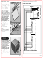
CONTROL PROCEDURE
RATING
3/4.5
4/6
6/9
8/12 10/15 9/18 12/24
DESIGN
AEROTHERMES
FUNCTIONS
ENGINE TYPE
PROPELLER
CONTACTOR TYPE
TEMPO START
INTENSITY
WALL MOUNTING BRAC.
SCREWS : NUTS
SENS DE ROTATION
DE L'HELICE
WARRANTY
APPLIANCE :
REFERENCE :
PROD. DATE :
RATING :
TENSION :
CONTROL :
RETAILLER
Date of sales :
USER
AT RECEPTION PLEASE CHECK YOUR APPLIANCE
Name :
Complete address :
INSTALLATION AND USER MANUAL
TO BE KEEPT BY THE USER
1- CHARACTERISTICS
P
- Adjustable fixation frame.
- Power supply junction box.
- Power contactor.
- Start and stop temporisation.
- Thermal cutout.
- Connection to Control box Réf. A750790 sold as accessory
making possible the functions described page 8 .
- Feet assembly available as accessory
- Five versions are possible :
Wall mounted fan heater without control box
Wall mounted fan heater with in board control box
Wall mounted fan heater with wall mounted control box
Mobile fan heater witout control box
Mobile fan heater with in board control box .
HEATING
REFERENCE
RATING
( kW )
3
4
6
8
10
9
12
VENTILATION
Tension Speed Flow
(V)
(tr / mn) (m3/ h)
6- WORKING WITH CONTROL BOX
L
A) VENTILATION :
H
- Switch Rep. 3 on position cold ventilation
The other functions like thermostat and heating
element are not in use.
Fig. 1
6
230 Mono
230 Tri
400 Tri
400 Tri+N
540
14
48
1300
660
15
1300
9
1000
12
15
18
230 Tri
400 Tri
400 Tri+N
1000
930
weight
(kg)
420 x 330 x 520
21
49
18
420
27 x 330 x 520
21
50
18
27
470 x 380 x 520
26
470 x 380 x 520
27
25
50
18
1400
1200
1000
930
16
1400
18
1200
1200
17
1000
1650
1400
1000
1600
18
1400
2310
24
25
16
16
53
53
37
22
52
55
19
32
22
53
20
29
32
50
56
1
2
3
+
Temp.
DIMENSIONS
Noise
(out of fixation)
increase
Air flow
( dB )
L x H x P ( mm )
(
°K
)
Cold
froid (m)
1300
Fig.8
- Switch Rep.3 on position ventilation-Heating
.
- Switch Rep. 2 on position Half speed
when mild weather and on position Full speed
when cold weather.
16
4.5
B) HEATING :
31
470 x 380 x 520
32
520 x 430 x 660
36
520 x 430 x 660
36
2- INSTALLATION ADVICES
When the desired room temperature is reached, turn slowly the dial of the thermostat on a
on a lower position until you ear a click comming from the relay or the built-in thermostat.
To avoid over comsumption, the fan will stop working only when the heat of the heating
element is gone.
7- CLEANING
This device is designed to cope to most difficult conditions, no need for maintenance.
However, in dusty aeras just clean the back grid.
IMPORTANT : Should you need to service the heater, it is compulsory to turn of the current.
with omnipolar switch off devices mounted on the main board.
( Rating and controls )
GOOD
- Lean slightly the fan heater to the soil in order to avoid air stratification under the ceiling.
( Pic. 2 and 3 ).
- Do not focus the air flow to directly cold walls or near to cold walls.
( Pic. 5 and 7 ).
- If several fan heaters are installed, the flows should not interfer (Pic. 4 and 6).
- Do not blow direct to people.
- In following these advices, you will save energy and ensure comfort.
Position the dial Rep.1 on position" ". You can hear the fan heater contactors connecting,
the fan will only start to blow when the heating element reach its accurate temperature
to offer a confortable air flow temperature.
Pic. 4
Pic. 6
WRONG
Pic. 2
Pic. 3
Pic. 5
Pic. 7
Page 2
Page 11
B) Fixation under ceiling : ( Pic. 10 )
C)Driving several fan heaters with one control box - A750790
Ceiling or horizontal
7
support
- Choose the support angle position
in fixing the cross bar in following holes
thanks to 2 M8 x 120 screws :
7.3 w/o cross bar = 0° ( horizontal )6.8 = 20° - 6.9 = 30° - 7.8 = 40° 9
7.9 = 43° - 7.1 = 57° - 6.1 = 58° 8
7.2 = 67° - 7.3 = 72° - 7.4 = 78° 6.2 = 80° - 6.3 = 90° ( vertical ) .
Position 7.3 is not suitable for ceilling
mounting but only on a support at more
than 1 meter down to the ceilling level.
In position from 7.1 to 6.3 the heater
becomes stratificator free and offers
important runing costs cutings .
- Unscrew the 4 screws and place the
pivot on the top of the heater
Rep. D then rescrew them . ( Pic11 ).
Pic. 10
- Further intallation procedure, see
section A of page 3 .
- Place the heater on its support
A
and tight the M12 screw (19 mm
wrench) Rep. A.
D
- Place the blocage clutches
C
( Rep. C ).
- Fix the heater in the desired position
tighten the screw A and the B nut
B
( 10 mm wrench).
Pic. 11
3
4
6
230 mono - Tri 230+N - Tri 400V+N
5
Cable
inlets
2
1
Control boxes
E
D
C
B
A
Thermostat
Fan heater N°1
B1
D
C
L1
L2
B
A
B
C
Pivot
Support
D
Fan heater
E
Fan heater N°2
4- WIRING AND
CONNECTION
- All fan heater installation shall be made
in accordance to the C15-100 norms
the section and protection of the power
cord wires must be in accordance to
the intensity board of page 5.
- Cables inlets are located at the back
of the fan heater ( Pic. 12 ).
- Connection and the tension change
of the heater must be conducted as
shown in pic. 13 and 14.
- To access to the junction box,
unscrew the 4 screws without removing
them, and sleeve the mobile hood
down .
Cable
inlets
B1
L1
L2
A
B
C
D
E
Same connection than N°2 for any additional fan heater
Mobile
hood
Pic. 12
Page 4
Page 9
The support is included in the carton box lining,
consisting in a) a hinged square
b) a cross bar
c) a pack of screws
r us Dia. 13
4 holes
The orientation pivot is fixed under the fan heater
as a standard.
76
Two fixation ways are possible:
A) Vertical fixation to a wall, a post, aso... :
- Use the hinged square ( Pic. 8 ) for the elevation
of the fixation holes.
- Fix the support with 4 screws or cramps.
- Adjust the cross bar in the hinged square, fins toward Pic. 8
inside. The gigger holes should be positionned same
side than the square holes of the hinged square. ( Pic. 9 ).
- Insert a M8 x 120 screw (from square holes side) in holes Pic. 6 or 7.
- Tighten with hand a M8 stop nut.
- Insert a second M8 x 120 screw in the desired inclination hole :
Tri 400V without neutral
Control boxes
E
D
C
B
A
241
P
N
20
Mono 230V
328
3- INSTALLATION AND FIXING ON SUPPORT
D) Driving several fan heater with only one control box
Thermostat
Fan heater N°1
110
- 6.3 or 7.5 = 0° ( horizontal ) 6.2 = 10° - 7.4 = 12° - 7.3 = 18° - 7.2 = 23° - 6.1 = 32°
- 7.1 = 33° - 7.9 =47° - 7.8 = 50° - 6.9 = 60° - 6.8 = 70° - 7.3 without cross bar = 90°
( vertical )
- The recommanded inclinations are shown in bold.
- Tighten the second M8 nut and block both M8 stop nuts.
Pic. 8 shows the dimension of the support together with the fixation drillings ( in mm )
of the hinged square.
Mounting the heater on the support
( see details ) :
- Place the heater on its
support and screw the A assemD
WALL
E
bly ( screw M12+fins ring )
with a 19 mm wrench.
- Place the 2 blocage clutch
( Rep. C ) and screw the nuts
( Rep. B ) by hand .
Cable
- Adjust the fan heater in the
inlets
F
choosen position .
- Block the A & B assemblies
Hinged
with 19 and 10 mm wrenches .
square
B1
L1
L2
A
B
C
D
E
Fan heater N°2
B1
L1
L2
A
B
Models
D
E
F
C
3/4.5 kW
4/6 kW
6/9 kW
8/12 kW
12/15 kW
9/18 kW
12/24 kW
635
430
350
635
635
430
430
350
400
635
430
400
635
430
400
685
685
480
480
450
450
D
E
Same connection then N°2 for any additional heater
Page 10
5
B
C
8 9
1 2 3 4
Pivot
6
A
Fan heater
241
Cross bar
B C
70
A
Detail
Pic. 9
7
Page 3
C) Cabling schem of fan heaters 9 / 18 kW et 12 / 24 kW :
A) Cabling schem of fan heaters 3 / 4.5 kW , 4 / 6 kW et 6 / 9 kW :
B) Cabling schem for fan heaters 8 / 12 kW et 10 / 15 kW :
Page 6
Page 7
5- CONTROL BOX
A) Connection of the control box :
- This control box is fitted with :
one 3 position switch : Arrêt
Cold ventilation
Ventilation + heating
one 2 position switch : Low speed
Full speed :
one accurate room thermostat only working when in position
- It can be fitted in board or on a wall.
- It should be connected on remote control junction boxes A, B, C, D , E respecting the
drawings of pages 9 and 10.
- Cord to be used : 5 x 1.5 mm² ( + Hearth in case of fixation at the back of the heater )
- The control box can drive up to 5 fan heaters.
- Note : the functions can also be insured with not supplyed accessories.
B) Control box cabling drawing :
Speeds
3 / 4.5 kW
1
2
1
2
1
2
1
2
1
2
1
2
4 / 6 kW
6 / 9 kW
8 / 12 kW
10 / 15 kW
9 / 18 kW
INPUT POWER PER PHASE
230 V MONO
230 V TRI
13.04 A
7.53 A
19.57 A
11.30 A
17.39 A
10.04 A
26.09 A
15.06 A
26.09 A
15.06 A
39.13 A
22.59 A
34.78 A
20.08 A
52.17 A
30.12 A
43.48 A
25.10 A
65.22 A
37.65 A
22.59 A
45.18 A
1
2
12 / 24 kW
400 V TRI
4.33 A
6.49 A
5.77 A
8.66 A
8.66 A
12.99 A
11.55 A
17.32 A
14.43 A
21.65 A
12.99 A
25.98 A
30.12 A
60.24 A
17.32 A
34.64 A
- The fan heaters are delivered in Triphase 400V + Neutral.
- The main current wires should be connected to dedicaded junction boxes
taking to tighten the screws.
- It is compulsory to connect the Neutral to the dedicated junction.
The resistances support frame is insulated and should remain insulated ( double isolation ).
- To change tension, please refer to Pic. 13 taking care to tighten carrefully the screws.
3
Red
Blue
Green
N
Works
2
Blue
Red
Blue
Green
Yellow
Yellow
White
White
Brown
Works
400V Tri
+N
1
Yellow
3
Blue
White
Yellow
Blue
Blue
White
2
Green
Red
Brown
Brown
Brown
1
Green
N
Red
230V Tri
+N
N
Blue
Red
Blue
Green
3
Brown
White
N
Blue
Blue
Yellow
3
2
Ph
Blue
Red
Blue
Green
Yellow
White
White
Green
brown
Red
Brown
1
Yellow
400V Tri
+N
230V Tri
+N
2
1
Brown
Brown
Fan heaters from 18 to 24 kW
Fan heaters from 4.5 to 15 kW
Thermostat
230V
Mono
E
D
C
B
A
Output
Fan heater
N
Pic. 13
Type of fan heater
NOTE :
The ventilator
always work under
230 volts monophased
Page 8
3 / 4.5 kW
4 / 6 kW
6 / 9 kW
8 / 12 kW
10 / 15 kW
9 / 18 kW
12 / 24 kW
Engine input current + Relais
2nd rating
0.32 A
0.32 A
0.52 A
0.79 A
0.79 A
0.74 A
0.78 A
Page 5