1
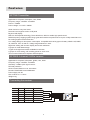
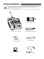
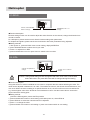
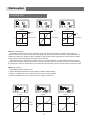
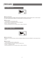
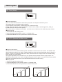
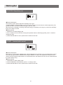
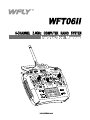
Preface
Vote of Thanks
Thank you for buying WFLY products. The WFLY300 is the latest technology in Rotary RC models.
Please read this manual carefully before assembling and flying the new WFLY300 helicopter. We
recommend that you keep this manual for future reference regarding tuning and maintenance.
THE MEANING OF SYMBOLS
Mishandling due to failure to follow these instrudions may result in damage or i nj ury.
Warning
Mishandl ing due to failure to follow these instrudions may result in danger.
Caution
Do not attempt under any circumst ances.
Prohibition
2
Features
WFT06II Transmitter
Applicable for: Airplane, Helicopters, Cars, Boats
Frequency range: 2.400Ghz 2.438Ghz
Power: ≤ 100MW
Power voltage: 3.7~6.0V ≤ 190MA
Great choice for entry level users
Dot-matrix and segment combo LCD panel
Big size LCD display
Native 2.4G Flaspeed technology. Direct drived from MCU to enable high speed control.
DSSS+frequency hopping system brings great anti-interference performance. 60 pcs of Wfly transmitters can
be working together at the same time.
Low voltage design for less power consumption. Compatible with variety types of battery: Alkaline 4S, NIMH
4S, NICD 4S, LiPo 1S and etc. Voltage range between3.7~6.0V.
Digital trim setting with numeric display and sound notification.
8 groups of model data storage.
4 types of left-right hand modes available for selection
5 groups of curve setting, with 5 editing points for each curve.
Tons of control funtions for airplane and helicopters.
WFR06S 6 channel 2.4Ghz receiver
Applicable for: Airplane, helicopters, gliders, cars, boats
Frequency range: 2.400Ghz 2.438Ghz
Sensitivity: -97dBm quick signal recover
Fail safe protection
Ground control distance: over 700 meters
Decode: PPM/PCMS 1024 PCMS4096
Power supply:4.8~6V
Size 34.85 X 21 X 11.3mm
Weight:5.8g
Connecting the receiver
Number Channel For airplane For helicopter
Aileron
Aileron
1
Ch1
Elevator
Elevator
CH2
2
Throttle
Throttle
CH3
3
Rudder
Rudder
CH4
4
Gyro
CH5 Lading Gear
5
Pitch
Flap
CH6
6
1
2
3
4
5
6
3
Product Configuration
Please carefully check the content accessories with below check list. Contact your
Caution
retailer for help if something is missing
1
2
3
4
5
6
WFR06S Receiver
WFT06II Transmitter
Battery compartment
Neck Strap
User manual
Warranty card
Simulator cable
4
Contents
3
4
6
7
8
9
10
10
11
11
12
12
12
13
13
14
15
15
16
17
17
18
18
19
19
20
20
21
21
22
22
23
24
25
26
26
27
27
28
28
29
29
30
Preface
product description transmitter / receiver
product configuration Packing list
safty warnings
Product diagram Front/ Back / Parts/ switchs
Basic operation
Edit keys / Display
operation and adjustment
Initial setup
A Back to factory default
B choose model number
C choose model type
D choose power supply
E - training /simulator mode
F - left-right hand mode
G - Control stick calibration
H - Coding
I fail safe protection
Helicopter function instruction
Menu introduction
Reverse setting
EPA setting
D/R setting
Sub trim
Trim step
Thurttle Hold
Thurttle cut
Timer setting
Normal thurttle curve
Idel thurttle curve
Swash setting
Gyro setting
Normal pitch curve setting
Idel pitch curve setting
Hold pitch curve setting
Other settings
Airplane funtion instructions
Menu introduction
Setting Page directory
Flaperon Mix
Flapron trim
Aileron differential
Elevator-Flaperon mix
Elevator
Elevator aileron mix
V-tail mix
Page directory
DELY Lading gear delay
5
FLYING SAFETY WARNINGS
Special Symbol Instruction
Caution
To use the product safely, please pay attention to the instruction as follows.
Please pay special attention to the symbol as follows:
Dangers:If you use it without proper operation, it is possible to hurt you
seriously or may even cause death.
Warning
Warnings:If you use it without proper operation, it may make you or others
to hurt badly or may even cause death, and it may cause slight hurt or
damage to things.
Notices:If you use it without proper operation, it may cause you to hurt
slightly or damage things , but it won't hurt you seriously normally.
Notices:Children under 14 must be accompanied and instructed by adults!
Notices: Turn on the transmitter first, then the receiver. When turning off the
system, turn off the receiver first, then the transmitter.
Notices: changes or modifications not expressly approved by the party
responsible for compliance could void the user's authority to operate the
equipment.
Prohibition
Flying Notice(warning)
Do not fly at night , in rain day ,or in strong wind, which will damage the
device or plane. This device is not water-proof.
Please check every servo works properly and eliminate any disturbing
signals before you play it.
6
Product view
Front view
Switch 5
antenna
Switch 2
antenna
Switch 1
Power switch
switch 4
Switch 3
TH.HOLD
TH.CUT
TIMER
D/R
CH 5
A:G EAR
H:GY RO
Elevator Trim
IDLE
AIL/ELE/RUD
TRAIN
A:CH 6
6 CH RC Radio System
Throttle trim
Rudder Elevator stick
Aileron / Throttle stick
Neckstrap attachment
Aileron Trim
Rudder Trim
LCD Display
Menu Button
+ button
UP button
- Button
Down Button
Switch description
Switch 1:Throttle hod on the middle postion.
Throttle cut on the upper position
Switch 2: Timer on the middle position. D/R on
the upper position
Switch 3: Training mode, Flaperon on Airplane
mode
Switch 4: Flying mode (Normal, Idel). ElevatorFlaperon mix for airplane
Switch 5: Channel 5 for Landing gear, Gyro for
helicopters
Back View
Training cable connector
/ data cable connector
Battery compartment
7
Basic operation
Edit buttons
Menu Button: Power on to enter stand by interface.
Press and hold Menu button, enter system setting interface.
In the system setting interface, press menu to switch to the
next function setting. Press and hold the menu button to
retun to stand by interface.
Up button: change the editing value towards
positive direction
Down button: change the editing value towards
negative direction
+ button: to edit parameters. Press and hold the + button to
speedly increase the value. You can also press and hold
the + button to confirm settings under specific function.
- Button: to edit parameters. Press and hold the - button to
speedly increase the value.
Display interface
Item this area displays the item under operation or
editing.
Menu this area displays the menu under operation
Number/Time This area is for item number or timer
Value: display setting parameters
Parameters this area displays the parameters under
operation or editing
Reverse display reverse setting status. NOR for
normal and REV for reverse
Channel / Switch this area show the channel or switch
being adjusted.
Model Number: stand by display item. H-01 means the
no.1 helicopters A-06 means No. 6 airplanes.
Funtion description: function discription display.
Timer: display stanby time
Voltage: display battery voltage
Setting item: displays the item name
Setting area: displays the setting parameter
Percentage: displays the parameter (percentage)
positive/negative and value.
Negative/positive: ↑ for positive ↓for negative
Value: display setting parameters
8
Basic operation
Basic operation
When you want to browse or change a current setting of the transmitter, please follow the procedure as
below,
1, press and hold menu button for 1 second to enter setting mode, the screen will show Menu REVR01
Initial interface Parameter setting mode Sub trim mode
2, Press Menu button, Item name will be changed according to the sequence, press until your intented option
being displayed. Eg. SUBT04 for sub trim. Description is SUBT menu sequence is 04;
3, Press UP/Down button to select the item to be edited, eg. CH2 channel value.
4, press +/- button to change the value
5, When changing the value under HOLD or CUT items, you need to press +/- button to activate the current
setting. (display ON) before you can use UP/DOWN button to switch between edit items, then use +/- button
to set your value.
6, Press Menu button to save after successfully changed the value and exit the current interface.
Caution Data will NOT be saved if you didn't press menu button to save and exit
Caution
Caution
Caution: The funtion of the transmitter are displayed in order, please read the setting instructions
before creat your model data. ( read the instructions carefully if you don't know how to use the
mix function)
9
Basic operation Initial setup
A Factory default
Press and hold Menu button
to enter setup. Press Menu
button 15 times.
After SYS being displayed
for one second, it will shows
the model number
When Sure blinking, press
and hold + to save.
Data save will complete after
WAIT being displayed for
one second
Press up button switch to
REST to reset, press down
button to confirm
●Menu display: SYS16 (helicopter mode ) - REST
●Function: SYS REST
●Function description: return to factory default setting. The default setting might be modified during
retailler's demostration. Use this function to return to factory default settings.
●Setting method :
1Press and hold Menu button to enter setup. Press Menu button 15 times, till SYS 16 Being displayed.
2 When MD H dsiplayed press up button switch to REST to return factory default setting
3 press down button to confirm, when Sure blinking, press and hold + to save. Press other button to cancel
edit.
B select mode number
Press +/- to select mode
number. The transmitter can
save upto 8 model data
Press +/- to select mode
number. The transmitter can
save upto 8 model data
Press down button to confirm
change, press and hold +
button to save
●Menu display: SYS16 Helicopters Mode - MD H / MD A
●Function: System parameter helicopter mode / Airplane mode
●Function description: when you have multiple models need to be used with this transmitter, choose the
pre-saved data can let you easily choose the data, don't have to set the parameters every time. This
transmeter can save up to 8 modle data with individule number for option.
●Setting method :
1 Press and hold Menu to enter system setting mode, press menu button 15 times until it shows SYS16;
2 when MD H or MD A being displayed, press+/- to change to your model number.
3 press down button to confirm, SURE will be shown during saving, press and hold + to save. Press any
other button to cancel edit.
10
Basic operation Initial setup
C- choosing model
Under SYS16 Press Up
button switch to Model
selection.
Press +/- to select Heli
ACRO means airplane
●Menu display: SYS 16 (helicopter mode) - HELI/ACRO
●Funtion: Model parameter model selection
●Funtion description: This transmitter support helicopters and airplane, you can select according to your
model.
●Setting method:
1 press and hold Menu to enter parameter setting mode, press Menu button 15 times, till SYS 16 being
displayed.
2 When MD H or MD A shown, press UP to choose model, Helicopter or Airplane, Press +/- to switch to your
model wanted.
3 Press down button to confirm operation, SURE will be shown during saving, press and hold +button to
save the change, press any other button to cancel edit.
D Choose Battery mode
Press MENU to NO.17
Press UP/DOWN to select
Press + to save
●Menu display: BAT 17 (Helicopter mode) - LI /NOR /NIMH
●Function: Battery mode - LI /NIMH
●Function description: This transmitter support multiple battery types. E.g. NOR for Alkaline 4S, NIHM/NICD
4S, LIPO/Lith 1S. Different type of batteries have different low voltage alarm value. Using correct battery
mode will extent the battery life.
Caution! Support voltage from 3.7~6.0V
Warning
●Setting method:
1, Press MENU to enter BAT battery type BAT 17
2, Press UP/DOWN switch between different types
3, Press and hold + button to confirm and save the setting.
11
Basic operation Initial setup
E Training/Simulator
●Menu display: TRSI 18 (Helicopter mode) NOR / TRA / SIMU
●Function: Training / Simulator Normal/Training mode / Simulator mode
●Function description:
1 NOR: Normal mode, RF 2.4Ghz working normally, can not work as a trainer but can be work as a trainee.
2 TRA: when this transmitter work as a trainer, the other transmitter work as a trainee through a training
cable. Using together with the training switch, the trainer is active when the switch disabled, when the
training switch is working, the trainee will be the activate transmitter.
3 SIMU: the RF2.4G will be shut off in order for connect with other transmitter or connect to the computer for
simulation training. Shutting the RF off will significantly increase the battery life.
●Setting method:
1, press and hold Menu button to enter TRSI, displayed as TRSI 18
2, When NOR/TRA/SIMU being displayed, press UP/DOWN to switch to the mode you need
3, Press and hold + button to confirm and save, press any other button to cancel the setting.
F STICK setting
1--Aileron
Mode 1
Mode 2
Mode 3
Mode 4
2--Elevator
3--Throttle
4--Rudder
●Menu display: STK 19 (Helicopter mode) - 1,2,3,4
●Function: Stick setting Mode1 mode2 mode 3 mode 4
●Function description: Stick setting will let the user to set the stick according to their habit. There are 4
different modes for option. If the transmitter has preset mode, please do not change by your own.
●Setting method:
1, press menu to enter STK, display STK19
2, Press UP/DOWN to switch to the mode you need
3, Press and hold + button to confirm and save the setting, press any other keys to cancel the setting.
G Stick calibration
●Menu display: CALI 20 (helicopter mode) CENT /LOW/ HIGH /OK/ERR
●Function: Stick Calibration- center position/ low position/ high position/ OK/ Error
●Function description: Stick calibration can be used to calibrate the stick after changing the stick mode.
●Setting method:
1, press menu to enter CALI, displayed CALI 20 for 1 second, and then CENT will be shown
2, press +/- button to switch to the channel need to be calibrated, e.g. CH1
3, when CENT displayed, Put the corresponding stick to the Center position, press Down button to confirm
and enter to the LOW Calibration, Push the stick to the left (Throttle and elevator to the bottom, Aileron and
rudder to the left side) Press down button to confirm and enter the HIGH calibration (Throttle and elevator to
the top, Aileron and rudder to the right side), press down button again, OK being displayed means the
calibration was successfully completed, if ERR being displayed, it means the calibration was fail and please
redo the process again.
4, repeat the process of step 2, 3 to complete the calibration for other channels.
5, The value will be displayed as -100% when the stick push to the bottom, displayed 0% on the center,
displayed as +100% when pushed to the top.
6,press menu button to save and exit after calibration successfully completed.
12
Basic operation Initial setup
H- Coding
●Menu display: COD 21 (helicopter mode)
●Function: Coding
●Function description: this transmitter is 2.4G DSSS+hopping system, with high anti-interference
performance. It is assigned with unique Address code, you need to coding with the compatible 2.4G
receivers.
Caution
Caution: when the transmitter in Simulator mode, the screen display OFF, coding function is
disabled.
●Setting method:
1, press Menu to enter COD
2, Press and hold + button to start coding. Coding process need to be completed in short distance. Coding
function is not active when 2.4G module being shut off. Please refer to TRSI training and simulator setting.
The screen will back to stand by mode after coding successfully complete. You can also press and hold
Menu button to exit.
Warning
Warning: Do not use the transmitter during coding process.
I Fail safe protection
●Menu display: F'S 22 (helicopter mode)
●Function: Fail safe
●Function description: This function is to protect the servo when the receiver disconnected with the
transmitter, the receiver will hold the servo in the current position or back to the preset position.
●Setting method:
1,press menu to enter F'S 22 Fail safe. When transmitter setting is TRSI, will display off. And the fail safe
function is shut off.
2, press up/down button to select channel every channel can be set individually. Servo will first move to
preset position. If the channel setting was in KEEP mode, the server will remain the last active position.
3, for safety consideration, throttle production setting is -150%, the motor will stop running when the
transmitter turns off. When throttle protection set to KEEP mode, please push the throttle stick to the bottom
before shutting off the transmitter. Please refer to the program setting procedure. Press down button to
switch to KEEP or preset mode. Press Menu button to save and exit after complete.
13
Helicopter
01
REVR Reverse
---------- - - - - - - - - --------- >>
15
02
EPA
EPA setting
---------- - - - - - - - - --------- >>
15
03
D/R
D/R setting
---------- - - - - - - - - --------- >>
16
04
SUBT Sub Trim
---------- - - - - - - - - --------- >>
17
05
TSTP Trim Step
---------- - - - - - - - - --------- >>
17
06
HOLD Throttle Hold
---------- - - - - - - - - --------- >>
18
07
CUT
---------- - - - - - - - - --------- >>
18
08
TIME Timer
---------- - - - - - - - - --------- >>
19
09
NTH
Normal throttle curve
---------- - - - - - - - - --------- >>
19
10
ITH
Idle throttle curve
---------- - - - - - - - - --------- >>
20
11
SWSH Swash
---------- - - - - - - - - --------- >>
20
12
GYO
GYRO
---------- - - - - - - - - --------- >>
21
13
NPI
Normal pitch curve
---------- - - - - - - - - --------- >>
21
14
IPI
Idle pitch curve
---------- - - - - - - - - --------- >>
22
15
HPI
Hold pitch curve
---------- - - - - - - - - --------- >>
22
16
SYS
System setting
---------- - - - - - - - - --------- >>
23
17
BAT
Battery mode
---------- - - - - - - - - --------- >>
23
18
TRSI Training / simulator mode
---------- - - - - - - - - --------- >>
23
19
STK
---------- - - - - - - - - --------- >>
23
20
CALI Stick calibration
---------- - - - - - - - - --------- >>
23
21
COD
Coding
---------- - - - - - - - - --------- >>
23
22
F'S
Fail safe
---------- - - - - - - - - --------- >>
23
Throttle cut
Stick setting
14
Helicopter
01-REVR
channel, use UP/DOWN
button to change
NOR/REVR, use +/- to
change
●Function description
Reverse setting function can be used to adjust the action direction of the channel, change the direction from
normal to reverse.
For Helicopters, please set the servo's direction before setting other parameters.
For Airplane and gliders, please set the servo's direction after other parameters being adjusted.
●Setting methods
1, after power on, press and hold menu to enter setting, displayed REVR01
2, press UP/DOWN button to select the CH you need
3, Press+/- to adjust Nor or REV
4, press and hold Menu to exit or press menu to switch to the next item.
02- EPA
channel use up/down to
change
Caution
bit rate, use +/- button to
change
Caution: Change EPA setting will also change de D/R Value. User need to set the EPA
before D/R value. The preset D/R value will be changed during EPA setting.
●Function description
Using this function to set the individual servo's travel on a specific direction without affecting the other. The
value can be adjusted in between 0% to 150%. The smaller the value is, the shorter the travel distance, and
vice versa. When the servo's setting on a specific direction is 0%, the servo will not move on that direction.
e.g. set the highest value of the throttle to avoid Carburetor overrun. Set the lowest value to choose the
proper Carburetor closing point.
●Setting method:
↓means the EPA negative ↑means the EPA positive
1, press and hold Menu button to enter setting mode after power on, shows EPA 02
2, press UP/Down to select the channel need to be adjusted
3, press +/- to change the value
4, press and hold menu button to exit setting or press menu button switch to next setting.
15
Helicopter
03-D/R/EXPO
Y output
Y output
Y output
120%
100%
60%
0%
X stick position
Default EPA
X stick position
biggest EPA
X stick position
EPA in small range
●Function description
Both this two functions are to set 2 different value and use specific switch to activate. DR is using on
Aileron elevator and rudder's control ratio, the bigger the ration, the greater the action. The greater action is
suitable for maneuver. Smaller action is suitable for those with precise requirements. This function normally
being adjusted after EPA setting with largest travel distance.
Parameter setting is through the change of the curve and parameters, to allow different sensitivity of the
control stick during the center point and the end point. Default value 0 means they have the same sensitivity,
the greater the value is, the sensitive on the end point and thus the more precise the action is and Vice versa
●Setting method
1, Select DR 03 under setting mode
2, press UP/DOWN select DR 1/2/3/4/ setting or EXPO 1/2/3/4/setting.
3, press +/- to adjust the ratio, switch D/R 1/2 to choose switch position.
4, press and hold Menu to exit or press menu to switch to next item.
Y output
Y output
X stick
position
Output default
Y output
X stick
position
output soft
16
X stick
position
output sensitivity
Helicopter
04- SUBT sub trim
●Function description:
When the trim setting is not able to achieve the necessary setting, use can use this function to further adjust
the value. Please put all the TRIM in the center position to use Sub trim function.
●Setting method
1, choose SUBT 04 under setting mode
2, press UP/Down to select the CH need to be adjusted
3 press +/- button to adjust the value
4, press and hold Menu to exit or press menu to switch to next item.
05 TSTP TRIM STEP
●Function description:
TRIM Step is to set the sensitivity of the trim setting by setting the step of the TRIM. The value range is from
1 to 20.
●Setting method
1, Choose TSTP 06 under the setting mode
2, press UP/DOWN to choose the channel you want to set
3, Press +/- to adjust the value
4, press and hold Menu to exit or press menu to switch to next item
17
Helicopter
06- HOLD Throttle hold
●Function description:
During landing, use throttle hold function to fix the throttle at a low level. The range of the throttle normally
set between -75% to +75%. For safety reason, when tuning the plane or helicopter on the ground, the throttle
POS need to be set to -75%, and hold the throttle, to avoid any mis-operation.
●Setting method:
When the setting active, use +/- button change INH (inhibit) into ON/OFF. Under this situation, when the
switch pushes to ON or OFF, the screen will display accordingly.
1, select HOLD 06 under setting mode
2, press +/- button to change status, press UP/DOWN button to set the throttle position (POS).
3, press and hold Menu to exit or press menu to switch to next item.
07 CUT throttle cut
●Function description
Throttle cut means after flying to turn off the engine. It is controlled by a switch. Active this function and the
engine will stop running when the switch turns on.
●Setting method
1. select CUT 07 under setting mode
2. press +/- to adjust the status, push up/down button to set the position POS and RATE.
3. Press and hold Menu to exit or press menu to switch to next item.
18
Helicopter
08 Time (timer)
●Function description:
Timer is to allow the transmitter to alarm before your plane or helicopter exhaust the power.
The largest setting is 99 minutes and 59 seconds
Control method: timer ON/OFF, Throttle upper limit, throttle lower limit.
Setting, TM to set minutes, TS for second, SW for switch control, THR↑for throttle upper limit, THR↓ for
throttle lower limit. POS for throttle position.
When timer reach 0, will beep for notification. If you don't turn off the timer, then it will beep every minutes.
●Setting method:
1, select TIME 08 under setting mode
2, press UP/DOWN select position, press +/- to change value
3, Press and hold Menu to exit or press menu to switch to next item.
09 N TH (Normal throttle curve)
●Function description:
Throttle curve is a curve with 5 editable points. It divided the throttle control into 5 areas. The editable value
range for the points is from 0 to 100%. In default situation 5 points can reach the throttle ration as shown on
picture 1. picture 2 is change the fifth point to 80%, when the stick in the range of 4/5 to 5/5. throttle raising
slowly and the max value is 80%.
Through the adjustment of the throttle curve, can optimize the stick position with the engine output. The
adjustment of the throttle curve need to be adjusted together with the pitch curve (refer to NPI section) which
allows the main RPM of the rotor can be maintained with the control stick moving.
●Setting method
1, select N TH 09 under setting mode
2, Press UP/DOWN to choose position, press +/- to change value
3, Press and hold Menu to exit or press menu to switch to next item.
10
75
50
25
0%
80
%
75
%
50
%
25
%
%
0%
0%
1
%
2
3
4
5
1
19
2
3
4
5
%
Helicopter
10- I TH (Idle throttle curve)
●Function description
NTH Normal Throttle curve and ITH idle throttle curve are for different situation. NTH is for normal situation,
ITH is for IDLE situation. Switch K4 on the upper situation is for IDLE on the lower position is for Normal
situation.
●Setting method
1, select ITH 10 under setting mode
2 press UP/DOWN to select position, press +/- to change value
3, Press and hold Menu to exit or press menu to switch to next item
10
75
50
25
0%
%
75
%
50
%
25
0%
1
80
%
%
%
%
0%
2
3
4
5
1
2
3
4
5
11- SWAH (Swash)
●Function description
Swash function is to adjust AIL, ELE PIT when selecting swash.
●Setting method: refer to basic process. When parameter is 1, normal mode, no swash supported. Swash
mode is activated when Parameter is 3. Use +/- button to change value.
1, select SWAH 11 under setting mode
2, press UP/down to select position, press +/- change value
3, Press and hold Menu to exit or press menu to switch to next item
20
Helicopter
12 GYRO Sensitivity mix
●Function description
This function can be used to adjust the sensitivity of the gyro.
3 modes available in this transmitter, normal, Idle, Hold. The Gyro has the same 3 modes respectively. The
greater the ratio is, the more sensitive the gyro, and vice versa.
When the servo is shaking or vibrating, that means the gyro sensitivity is too high, try to lower the sensitivity
till the servo back to normal.
●Setting method
1, select EYO 12 under setting mode
2, use +/- button to turn the function on/off, press up/down button to select flying mode, press +/- button to
change the value.
3, Press and hold Menu to exit or press menu to switch to next item
13 NPI (normal pitch curve)
●Function description
Pitch curve is a curve with 5 editable points. With the adjustment of the pitch curve, can optimize the control
stick with flying performance. Editable value range is between 0~100%. The adjustment of the pitch curve
need to be used combined with throttle curve which allows the main RPM of the rotor can be maintained with
the control stick moving.
●Setting method
1, choose NPI 13 under setting mode
2, Press UP/DOWN to select position, press +/- to change value
3, Press and hold Menu to exit or press menu to switch to next item
21
Helicopter
14 IPI Idle pitch curve
●Function description
Use this function to set the pitch curve for idle flying. The curve has 5 editable points. When idle
mode is active, the idle pitch curve will optimize the engine and rotor's output. The editable value
range is between 0 ~100%. Do not set the highest value over the max value that corresponding to
the max engine RPM value. Normally we set to one step smaller. The minimum pitch will base on the
maneuver's specific requirement.
●Setting method:
1, choose IPI 14 under setting mode
2, press up/down to choose position, press +/- to adjust the value
3, Press and hold Menu to exit or press menu to switch to next item
15 HPI (throttle hold Pitch curve)
●Function description
This function is to set the pitch curve when the throttle being held.
●Setting method
1, select H PI 15 under setting mode
2, press UP/DOWN to select position, press +/- to change the value
3, Press and hold Menu to exit or press menu to switch to next item
22
Helicopter
16- SYS【system settings】
●Please refer to page 11
17- BAT【Battery mode】
●Please refer to page 11
18- TRSI【Training and simulator】
●Please refer to page 12
19- STK【Stick Mode (Left right hand)】
●Please refer to page 12
20- CAIL【Stick Calibration】
●Please refer to page 12
21- COD【Coding】
●Please refer to page 13
22- F'S【Fail safe setting】
●Please refer to page 13
23
setting menu introduction
Airplane
01
REVR Reverse setting
---------- - - - - - - - - --------- >>
25
02
EPA
EPA setting
---------- - - - - - - - - --------- >>
25
03
D/R
DR setting
---------- - - - - - - - - --------- >>
25
04
SUBT SUB Trim setting
---------- - - - - - - - - --------- >>
25
05
TSTP Trim step setting
---------- - - - - - - - - --------- >>
25
06
HOLD Throttle hold
---------- - - - - - - - - --------- >>
25
07
CUT
---------- - - - - - - - - --------- >>
25
08
TIME TIMER
---------- - - - - - - - - --------- >>
25
09
NTH
---------- - - - - - - - - --------- >>
25
10
FLER Flap aileron mix control ---------- - - - - - - - - --------- >>
26
11
FTRM Flap trim setting
---------- - - - - - - - - --------- >>
26
12
ADIF Aileron differential
---------- - - - - - - - - --------- >>
27
13
ELFL Elevator-Flaperon mix ---------- - - - - - - - - --------- >>
27
14
ELEV Elevator
---------- - - - - - - - - --------- >>
28
15
AILV
---------- - - - - - - - - --------- >>
28
16
VTAL V-tail mix
---------- - - - - - - - - --------- >>
29
17
SYS
System settings
---------- - - - - - - - - --------- >>
29
18
BAT
Battery mode
---------- - - - - - - - - --------- >>
29
19
TRSI Training / simulator
---------- - - - - - - - - --------- >>
29
20
STK
Stick setting (left right hand) -- - - - - - - - - ---------- - - - >>
29
21
CALI Stick calibration
---------- - - - - - - - - --------- >>
29
22
COD
Coding
---------- - - - - - - - - --------- >>
29
23
F'S
Fail safe
---------- - - - - - - - - --------- >>
29
24
DELV DELY Lading gear delay---------- - - - - - - - - --------- >>
30
Throttle cut
Normal throttle curve
Elevator aileron mix
24
Airplane
01- REVR【reverse setting】
●Please refer to page 15
02- EPA【EPA setting】
●Please refer to page 15
03- D/ R【D/R setting】
●Please refer to page 16
04- SUBT【SUB trim】
●Please refer to page 17
05- TSTP【Trim step】
●Please refer to page 17
06- HOLD【Throttle hold】
●Please refer to page 18
07- CUT【throttle cut】
●Please refer to page 18
08- TIME【timer】
●Please refer to page 19
09- NTH【Normal throttle curve】
●Please refer to page 19
25
Airplane
10- FLER (Flap aileron mix control)
●Function description
This function is to for aileron to act like flaperon even using two servos on aileron. Due to flaperon, aileron
can move up or down accordingly. Aileron differential can also be achieved.
AIL 1 ↓ aileron 1 down; Ail1 aileron 1 up; Ail2 aileron 2 down; AIL2 aileron2 UP; FLP1 Flap 1; FLP2 FLAP
2.
●Setting method
1, select FLER 10 under setting mode
2, press +/- button to switch between ON/OFF, press UP/DOWN to choose the position, press +/- to change
value.
3, Press and hold Menu to exit or press menu to switch to next item
Caution
Caution:Elevator aileron, V tail mix, elevator mix can not be operated together at the
same time. Elevator, Flap aileron mix and aileron differential can only be operate
one function each time. WARN will be displayed when those are activated
together. Please turn off the rest before using it.
11-FTRM Flaperon trim
●Function description
Use this function to adjust the center point of flaperon aileron mix.
●Setting method
1, select FTRM 11 under setting mode
2, press +/- button to switch between ON/OFF, press UP/DOWN to choose the position, press +/- to change
value.
3, Press and hold Menu to exit or press menu to switch to next item
26
Airplane
12 ADIF aileron differential
●Function description
This function is to use to make differential for the aileron on both sides when using 2 servos.
AIL1↓ Aileron 1 down AIL1↑ Aileron 1 up AIL2↓ aileron 2 down AIL2↑ AILERON2 up
When turning using aileron, you will need more aileron travel on up direction.
●Setting method
1, select ADIF 12 under setting mode
2, press +/- button to switch between ON/OFF, press UP/DOWN to choose the position, press +/- to change
value.
3, Press and hold Menu to exit or press menu to switch to next item
●About Flap-aileron mix and aileron differential
You need to choose one mode which is more suitable for yourself. If you would like to let the aileron work just
like flaperon, you will better choose FLER. If you have 2 aileron servos and 2 flaperon servos, ADIF will be a
better choice.
13. ELFL Elevator Flaperon mix
●Function description
This function is for flaperon and elevator can act respectively. In any situation, the move of elevator will lead
to the raise or down of flaperon, in order for better performance on idle maneuver. Most of the time when
elevator goes up, flap goes down. Use the switch to control this function.
RATE↑ Flaperon upper travel mix rate RATE↓ Flaperon lower travel mix rate
●Setting method
1, select ELFL 13 under setting mode
2, press +/- button to switch between ON/OFF, press UP/DOWN to choose the position, press +/- to change
value.
3, Press and hold Menu to exit or press menu to switch to next item
27
Airplane
14 ELEV elevator
●Function description
This function is for the combination of elevator and aileron, allow the use of delta-wing, Guts-wing, and
ailless aircraft. User can adjust the aileron and elevator separately.
AIL1 ↓ aileron 1 down AIL1↑ aileron 1 up, AIL2 ↓ aileron 2 down, AIL2 ↑ Aileron2 UP ELE1 Elevator 1
ELE2 elevator 2
●Setting method,
1, select ELEV 14 under setting mode
2, press +/- button to switch between ON/OFF, press UP/DOWN to choose the position, press +/- to change
value.
3, Press and hold Menu to exit or press menu to switch to next item
15-AILV Elevator-Aileron mix
●Function description
This function is to control elevator by one servo, and combine the elevator and aileron's function in together.
Due to the affect from the aileron, elevator and aileron will act in opposite direction.
AIL3 aileron 3 travel ELE1 elevator 1
●Setting method
1, select AILV 15 under setting mode
2, press +/- button to switch between ON/OFF, press UP/DOWN to choose the position, press +/- to change
value.
3, Press and hold Menu to exit or press menu to switch to next item
28
Airplane
16 VTAL (v tail mix control)
●Function description
This function is to combine the function of elevator and rudder when using v tail airplane. The travel of
elevator and rudder can be adjusted independently.
ELE1 elevator 1 ELE2 elevator 2 RUD1 rudder1 RUD2 rudder 2
●Setting method:
1, select VTAL16 under setting mode
2, press +/- button to switch between ON/OFF, press UP/DOWN to choose the position, press +/- to change
value.
3, Press and hold Menu to exit or press menu to switch to next item
17- SYS【system setting】
●please refer to page 11. NOTE: Item order could be different
18-BAT【Battery mode】
●please refer to page 11.
19- TRSI【Training / simulator】
●please refer to page 12
20- STK【Stick setting (left right hand)】
●please refer to page 12
21- CAIL【Stick calibration】
●please refer to page 12
22- COD【Coding】
●please refer to page 13
23- F'S【Fail safe】
●please refer to page 13
29
Airplane
24 - DELY Lading gear delay.
24
5 20
●Function description
This function is to set the delay of the landing gear of a airplane. The parameter can be adjusted between
0~100, which is 0~5 seconds accordingly. 0 means no delay, 1 means 50ms delay and so forth. The delay
will be 5 seconds with set to 100.
●Setting method:
1, select DELY 24 under setting mode.
2, press +/- to change value.
3, press and hold menu to exit or press menu to switch to next item.
30
www.wflysz.com
shenzhen WFLY technology development Co., Limited