1
OPEN
DRIVE
OPEN DRIVE
Brushless Manual
Revision 4,0
GENERAL INDEX
1. Standard closed loop application
1.
2.
3.
4.
5.
Application configuration
References management
Analog outputs management
Input logic management
Logic outputs management
2. Common functions
1.
2.
3.
4.
5.
6.
7.
8.
Storage and recall of the working parameters
Voltage break control for mains feeding
Braking management
Power soft start
Sequences of drive switch on and switch off
Thermal protections hardware
Current/power relay
Active bank parameters
3. Brushless core
1.
2.
3.
4.
5.
Complete list of control values
Setting basic parameters
Auto-tuning procedures
Regulation
Maintenance and controls
4. Feedback Options
1. TTL encoder (for asynchronous motors only)
2. Resolver (for asynchronous, brushless and reluctance motors )
3. Encoder and hall sensors (for brushless and reluctance motors )
4. Incremental sin cos encoder (for asynchronous motors only)
5. Absolute sin cos encoder (for brushless and reluctance motors )
6. Endat 2,2 (for asynchronous, brushless and reluctance motors )
7. Endat 2,1 (for asynchronous, brushless and reluctance motors )
8. Simulated encoder signals
9. Configuration of the encoder simulation output
10. Sensor type alarm
5. Remote Keypad
1.
2.
3.
4.
Physical disposition
Layout of the internal dimensions
Status of rest
Main menu
6. Modbus Protocol
1. Application Configuration
2. Managed services
7. CANBUS
1. Configuration of the application
2. Managed services
8. Supervisor
1.
2.
3.
4.
5.
6.
Introduction
Minimum system requirements
Software installation
Connection with the drive
Getting started
Pages description
OPEN DRIVE
OPEN DRIVE
Standard closed loop
application
OPEN DRIVE
Standard closed loop application
Standard closed loop application
(references generation)
CONTENTS
1.
Application configuration ........................................................................................................ 2
1.1.
Application parameters .................................................................................................... 2
1.2.
Application connections ................................................................................................... 3
1.3.
Input logic functions ........................................................................................................ 4
1.4.
Application internal quantities ......................................................................................... 4
2. References management .......................................................................................................... 4
2.1.
Digital and analog references management ..................................................................... 6
2.1.1.
14 bit analog references ............................................................................................... 7
2.1.2.
Digital speed reference (Jog) ....................................................................................... 8
2.1.3.
Digital Potentiometer speed reference ......................................................................... 8
2.1.4.
16 bit analog speed reference (optional) ...................................................................... 9
2.1.5.
Speed frequency reference decoded in time ................................................................ 9
2.2.
Speed frequency reference management........................................................................ 10
2.2.1.
High resolution analog reference (optional) .............................................................. 10
2.2.2.
Frequency reference ................................................................................................... 11
2.2.3.
Time decode of frequency input ................................................................................ 12
2.2.3.1.
Electric axis with frequency reference decoded in time ........................................ 13
2.3.
Multiplicative factor on speed reference ........................................................................ 14
2.4.
Torque feed-forward on speed reference ....................................................................... 15
2.5.
Speed regulator second parameters bank ....................................................................... 16
3. Analog outputs management .................................................................................................. 17
4. Input logic management ......................................................................................................... 19
4.1.1.
Input logic functions set in other ways ...................................................................... 20
4.1.2.
Locked Run from terminal board ............................................................................... 20
5. Logic outputs management .................................................................................................... 21
1/1
Rev. 1.7 08.06.09
Standard closed loop application
OPEN DRIVE
The OPEN DRIVE standard application makes it possible to control the motor in speed or in current
by inputting the references analogically and digitally. Management of digital input/output and
Field-Bus references can also be carried out.
1. Application configuration
1.1. Application parameters
PAR
P01
P02
P03
P04
P05
P06
P07
P08
P09
P10
P11
P12
P13
P14
P16
P17
P20
P48
P49
P180
P181
P182
P183
P184
P185
P186
P187
P188
P189
P190
P191
DESCRIPTION
14 bit analog ref. correction factor 1 (AN_INP_1)
14 bit analog corrective offset ref. 1 (AN_INP_1)
14 bit analog ref. correction factor 2 (AN_INP_2)
14 bit analog corrective offset ref. 2 (AN_INP_2)
14 bit analog ref. correction factor 3 (AN_INP_3)
14 bit analog corrective offset ref. 3 (AN_INP_3)
Digital speed reference (JOG1)
Digital motor potentiometer starting speed
Analog torque reference time filter constant
Offset on high precision analog reference
NUM – Frequency input slip ratio
DEN – Frequency input slip ratio
Correction factor for analog speed reference at 16 bit
Offset correction factor for analog speed reference at 16
bit
Maximum motor potentiometer speed reference
Minimum motor potentiometer speed reference
Digital potentiometer acceleration time
Speed reference frequency input time filter constant
Correction factor for Speed reference frequency input
Torque Feed-forward: II order time filter constant on
speed reference
Torque Feed-forward: Startup time
% Increment multiplicative factor on speed reference
% Decrement multiplicative factor on speed reference
Velocità massima di lavoro – SECOND BANK
KpV speed regulator – SECOND BANK
TiV speed regulator – SECOND BANK
TfV (filter) – SECOND BANK
CW acceleration time – SECOND BANK
CW deceleration time – SECOND BANK
CCW acceleration time – SECOND BANK
CCW deceleration time – SECOND BANK
Variation
FIELD
±400.0
±16383
±400.0
±16383
±400.0
±16383
±100.00
±100.0
0.0÷20.0
±19999
±16383
0÷16383
±400.0
±16383
Default
VALUE
100.0
0
100.0
0
100.0
0
0.00
2.0
0.0
0
100
100
100.0
0
Normalisation
UNIT
%
16383=100%
%
16383=100%
%
16383=100%
% n MAX
% n MAX
ms
/100 mV
%
16383=100%
internal
Repr.
10
1
10
1
10
1
16383
16383
10
1
1
1
10
1
±105.0
±105.0
0.3÷1999.9
0.0÷20.0
0÷200.0
0.0÷1000.0
105.0
-105.0
50.0
1.6
100.0
0.0
% n MAX
% n MAX
s
ms
%
ms
16383
16383
10
10
16383
10
0÷19999
100.0 ÷ 800.0
0.0 ÷ 100.0
50-30000
0.1÷400.0
0.1÷3000.0
0÷25
0.01÷199.99
0.01÷199.99
0.01÷199.99
0.01÷199.99
0
100.0
0.0
2000
4.0
80.0
0.8
10.00
10.00
10.00
10.00
ms
%
%
Rpm
1
4095
4095
1
10
10
10
100
100
100
100
1/2
Rev. 1.7 08.06.09
ms
ms
s
s
s
s
Standard closed loop application
OPEN DRIVE
1.2. Application connections
CON
C01
C02
C03
C04
C05
C06
C07
C08
C09
DESCRIPTION
Logic input 1 meaning
Logic input 2 meaning
Logic input 3 meaning
Logic input 4 meaning
Logic input 5 meaning
Logic input 6 meaning
Logic input 7 meaning
Logic input 8 meaning
Frequency input determination :
Variation
FIELD
-1÷63
-1÷63
-1÷63
-1÷63
-1÷63
-1÷63
-1÷63
-1÷63
0÷3
Default
value
8
2
3
0
4
12
5
22
1
Meaning
of default
RESET ALL
CONSENT
ENABLE REF AI1
RUN
ENABLE REF AI2
CW/CCW
ENABLE JOG
ENABLE RAMPS
DIGITAL
ENCODER
Type
RUN
RESET READY
END OF RAMP
SWITCH ON
POWER INPUT
CURRENT
SPEED
SPEED REF
TORQUE REF
LIMIT REF
r
r
r
r
0=analog; 1=digital encoder;
2=digital frequency/sign; 3=digital frequency/sign 1 edge
C10
C11
C12
C13
Logic output 1 meaning
Logic output 2 meaning
Logic output 3 meaning
Logic output 4 meaning
-32÷31
-32÷31
-32÷31
-32÷31
3
0
6
10
C15
C16
C17
C18
C19
C20
C22
C23
C24
C25
C26
C31
C36
C39
C40
C43
C52
C53
C70
Meaning of programmable analog output 1
Meaning of programmable analog output 2
Meaning of 14 bit analog input A .I.1
Meaning of 14 bit analog input A .I.2
Meaning of 14 bit analog input A .I.3
Load last digital potentiometer frequency
Enable 14 bit analog reference A.I.1
Enable 14 bit analog reference A.I.2
Parallel bit at REF3 (jog)
Parallel bit at REF4 (digital motor potentiometer)
Ramp inclusion
Enable 14 bit analog reference A.I.3
Reference signal software reversal
Impulses/revolution selection FREQUENCY INPUT
Enable 16 bit analog speed reference
Enables speed reference in frequency
Enable FIELD-BUS references
Enable locked RUN
Enable Speed reference frequency input decoded in
time
Enable digital inputs active low
Enable Torque feed-forward on speed reference
-63÷64
-63÷64
0÷2
0÷2
0÷2
0.1
0,1
0,1
0,1
0,1
0,1
0,1
0,1
0÷9
0,1
0,1
0,1
0,1
0,1
11
4
0
1
2
0
0
0
0
0
x
0
0
5
0
0
0
0
0
0÷255
0÷2
0
0
0,1
0,1
0
0
0÷4
0
0÷3
0
0,1
0
C79
C90
r
r
r
r
r
r
r
r
r
r
r
r
1024 ppr
r
r
r
0=not enabled; 1=analog speed ref; 2=frequency speed reference
C91
C92
C93
Enable offset on overlap position loop reference
Enable overlap position loop memory clear when power
is switched-off
Analog input selection for multiplicative factor
0=none 2=AI2 3=AI3 4=AI16bit
C94
Speed reference selection with multiplicative factor
0=none 1=AI enabled 2=AI16bit 3=NUM electrical gear
C95
Active bank speed regulator gains
1/3
Rev. 1.7 08.06.09
r
Standard closed loop application
OPEN DRIVE
1.3. Input logic functions
INP
I00
I01
I03
I04
I05
I06
I07
I09
I10
I11
I12
I14
I18
I19
I20
I21
I22
I24
I25
I26
LOGIC FUNCTION ASSIGNED
Run
Torque control
Enable 14 bit analog reference A.I.1.
Enable 14 bit analog reference A.I.2.
Enable speed jog
Enable digital potentiometer speed reference
Enable 14 bit analog reference A.I.3.
DP UP digital potentiometer up
DP DOWN digital potentiometer down
Load last digital potentiometer value
Reference reversal
Enable FIELD-BUS references
Enable speed reference in frequency decoded in time
Enable speed reference in frequency
Enable 16 bit speed reference (if present)
STOP command (run with retention)
Enable line ramps
Freeze PI speed regulator integral memory
Enable offset on overlap position loop reference
Enable second bank speed regulator gains
1.4. Application internal quantities
INT
INTERNAL ASSIGNED VARIABLE
d06
d10
d12
d14
d32
d33
16 bit analog speed reference
Reference for torque generated by the application
14 bit analog speed reference
Reference for speed in frequency generated by the application
Reference for torque limit generated by the application
Reference for speed percentage generated by the application
Normalisation
unit
% n MAX
% C NOM MOT
% n MAX
% n MAX
% C NOM MOT
% n MAX
Internal
repr.
16383
4095
16383
16383
4095
16383
2. References management
The standard application regards the configuration and management of various digital inputs for the
generation of speed, torque and torque limit references for the actual control of the motor.
1/4
Rev. 1.7 08.06.09
Standard closed loop application
OPEN DRIVE
Application
Fieldbus
Motor
control
Analog
inputs
t_rif
A.I.1 (14bit)
A.I.2 (14bit)
A.I.3 (14bit)
Torque reference
Analog and
Digital
References
management
[ % Nominal motor torque]
Limit_i_aux
Torque limit
[ % Nominal motor torque]
f_somma_tot
[ % maximum speed]
A.I.16 (16bit)
optional
Frequency
input
A
/A
B
/B
+
f_tempo
Digital ref.
Speed reference
[ % maximum speed]
+
Frequency
reference
management
theta_precision
[electrical pulses per Tpwm]
theta_rif_pos
[electrical pulses per Tpwm]
Position reference for overlap
space loop
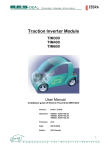
5 references for the motor control are generated by this block:
1. a torque reference (“t_rif”) as percentage of the motor's nominal torque
2. a torque limit reference (“limit_i_aux”) as percentage of the motor's nominal torque.
3. a speed reference (“f_somma_tot”) as percentage of the maximum speed (set in parameter
P65)
4. another speed reference (“theta_precision”) in electrical pulses for the period of PWM. This
particular reference is to ensure no pulse is lost if frequency input is used. Internal
normalisation requires there to be 65536 pulses per mechanical revolution and these are
considered the pulses multiplied by the motor's number of polar pairs: this so as not to lose
sensor resolution.
5. a incremental position reference (“theta_rif_pos”) in electrical pulses for the period of
PWM, that will be the reference for the overlap space loop.
Inside the motor control, the two speed references are added up after they have been suitably
adapted.
1/5
Rev. 1.7 08.06.09
Standard closed loop application
OPEN DRIVE
2.1. Digital and analog references management
References from Field_Bus
I.03
±10V A
0
+
14BIT
+
A.I.1
C17
C22
2
P2
P1
1
D
A.I.2
+
P3
C23
C18
+
0
+
1
D
A.I.3
C31
+
P5
Torque limit
(“limit_i_aux”)
+
+
multiplicative
factor
if C94=1
+
C19
2
P6
C52
Or
I14
D12
±105%
P16
Digital potentiometer
DP LV
P8=±100%
+
+
C25
C20 o I11
DP UP
D32
+
±10V
14 BIT
“limit_fieldbus”
+
2
P4
I.07
A
P9
C52
Or
I14
0
+
D10
Torque
reference
(“t_rif”)
+
+
+
I.04
14BIT
A
“trif_fieldbus”
+
+
1
D
±10V
C52
Or
I14
+
+
“f_fieldbus”
+
D33
Speed reference
(“f_somma_tot”)
+
I.06
DP DOWN
P17
±105%
ON LINE
D06
I.20
±10V
A
A.I.16
multiplicative
factor
if C94=2
16 BIT
+
C70
D
+
P13
P14
C40
Jog
C24
I.18
P7
±100%
I.05
Speed frequency reference
decoded in time
(“f_tempo”)
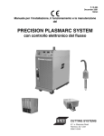
It’s possible to enable separately all references using connections or logic input functions.
For speed and torque references the active reference is the sum of all enabled references, for torque
limit prevails the more constrain active reference, between the sum of analog and the Fieldbus
references.
1/6
Rev. 1.7 08.06.09
Standard closed loop application
OPEN DRIVE
2.1.1.
14 bit analog references
There can be up to 3 differential analog inputs (A.I.1 ÷ A.I.3) ± 10V which, after being digitally
converted with a resolution of 14 bits, can be:
o
o
o
o
conditioned by digital offset and a multiplicative coefficient
enabled independently through configurable logic inputs or connections
configured as meaning through the corresponding connection (C17 ÷ C19)
added together for the references with the same configuration
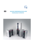
For example in the case of A.I.1, the result of the conditioning is given by the following equation:
REF1= ((A.I.1/10)*P1) + P2
By selecting a suitable correction factor and offset the most varied linear relationships can be
obtained between the input signal and the reference generated, as exemplified below.
REF
100%
-10V
REF
REF1
100%
+100%
-5V
+10V
Vin
+5V
Vin
P1=200.0
P2=0
P1=100.0
P2=0
0
-100%
-100%
+10V Vin
P1=200.0
P2=-100.0
Default setting
REF1
REF1
100%
100%
P1=80.0
P2=20.0
20%
0
+10V
Vin
P1=-80.0
P2=100.0
20%
+10V
Vin
Note: for the offset parameters (P02, P04 and P06) an integer representation has been used on the
basis of 16383, in order to obtain maximum possible resolution for their settings.
For example if P02=100
offset = 100/16383 = 0.61%
As said above, the enabling of each analog input is independent and can be set permanently by
using the corresponding connection or can be controlled by a logic input after it has been suitably
configured.
For example to enable input A.I.1 the connection C22 or the input logic function I03 can be used,
with the default allocated to logic input 3.
1/7
Rev. 1.7 08.06.09
Standard closed loop application
OPEN DRIVE
The connections C17 ÷and C19 are used to separately configure the three analog inputs available:
C17 – C19
0
1
2
Meaning
Speed reference
Torque reference
Torque limit reference
Several inputs can be configured to the same meaning so that the corresponding references, if
enabled, will be added together.
Note: using the appropriate multiplicative coefficient for each reference it is therefore possible to execute the
subtraction of two signals.
In the case of the torque limit, if there is no analog input configured to the given meaning and
enabled, the reference is automatically put at the maximum that can be represented, i.e. 400%. In
internal quantities d32 it is possible to view the torque limit imposed by the application.
In the case of the torque reference there is a first order filter with time constant that can be set in
milliseconds in parameter P9. In the internal quantity d10 the torque reference can be viewed as set
by the application
2.1.2. Digital speed reference (Jog)
The value programmed in parameter P7 can be used as digital speed reference either by activating
the logic function “Enable Jog” I.05 assigned to an input (default input L.I.5) or with the connection
C24=1. The resolution is 1/10000 of the maximum working speed.
2.1.3. Digital Potentiometer speed reference
A function that makes it possible to obtain a terminal board adjustable speed reference through the
use of two logic inputs to which are assigned the input functions digital potentiometer up I09”
(DP.UP) and “Digital potentiometer down I10” (DP.DOWN) .
The reference is obtained by increasing or decreasing an internal counter with the DP.UP and
DP.DOWN functions respectively.
The speed of increase or decrease set by parameter P20 (acceleration time of the digital
potentiometer) which sets how many seconds the reference takes to go from 0 to 100%, keeping the
DP.UP active (this times is the same as to go from 100.0% to 0.0% by holding DP.DN active). If
DU.UP are DP.DOWN are activated at the same time the reference remains still.
The movement of the reference is only enabled when the converter is in RUN.
The initial reference value at the time of start up of the converter, is set by the value programmed by
the parameter P8 ( P8=2.0% default) if neither the function “last digital potentiometer value I20”
(DP.LV not active by default), nor connection C20 (C20=0 default) is active, while the initial
reference value remains the same as that when the converter was stopped, even if power has been
removed in the meantime, when the DP.LV function is active or connection C20 is active. Thanks
to this permanent memory, even if the power supply is lost, the digital potentiometer can be used as
if it were a physical potentiometer.
1/8
Rev. 1.7 08.06.09
Standard closed loop application
OPEN DRIVE
The functioning is summarised in the following table :
Converter
running
on-line
H
H
H
H
L
L -> H
L -> H
L -> H
L -> H
H = active
DP.UP
DP.DOWN
DP.LV
C20
REF
H
L
L
H
x
x
x
x
x
L
H
L
H
x
x
x
x
x
x
x
x
x
x
L
H
L
H
x
x
x
x
x
L
L
H
H
increases
decreases
stopped
stopped
stopped
P8
REF4 L.v.
REF4 L.v.
REF4 L.v.
x = does not matter
L = not active
L -> H = From Off-line to On-line
The digital potentiometer reference requires, to be enabled, activation of function I06 after
allocating an input or activating connection C25 (C25=1) .
In the parameters P16 and P17 the maximum and the minimum admitted reference values can be
marked for the digital potentiometer reference.
2.1.4. 16 bit analog speed reference (optional)
When very precise speed sensors such as Sin/Cos Encoders, Endat can have an analog speed
reference ± 10V converted into 16 bit digital so also to have an excellent resolution reference.
For correct wiring of this 16 bit speed reference see the speed sensor appendix to the installation
manual.
Also for this speed reference it possible to condition with offset and multiplicative coefficient:
REF16= ((A.I.16/10)*P13) + P14
The 16 bit analog speed reference requires activation of function I20 after assigning an input or
activation of connection C40 (C40=1) .
In internal quantity d6 this reference can be viewed as a percentage of the maximum working
speed.
2.1.5. Speed frequency reference decoded in time
The speed frequency reference decoded in time can be used as digital speed reference either by
activating the logic function I.18 assigned to an input or with the connection C70=1.
View in paragraph 2.2.3 for more detailed explanation.
1/9
Rev. 1.7 08.06.09
Standard closed loop application
OPEN DRIVE
2.2. Speed frequency reference management
This speed reference in pulses (“theta_precision”) can be provided in 3 different ways (alternatives
to each other), that can be selected by means of connection C09.
C 09
0
1
2
3
Mode of working
Analog reference ±10V (optional)
4 track frequency reference (default)
Frequency reference (freq. and up/down) counting all edges
Frequency reference (freq. and up/down) counting one edge
C 0 9 inp ut co nfiguratio n
P 1 0 O ffset
0 = voltage con verted in f
1 = d igital en c od er
2 = freq u en cy/sign
3 = freq u en cy/sign 1 ed ge
P 8 8 V o ltage co rresp o nd ing to
m axim um sp eed
2 16
B ASE
+
0
I1 9
Z -1
E nco d er
Inp ut
S p eed reference in
p ulses
(“theta_ p recisio n”)
C 09
C43
P11
2 16
B ASE
1 ,2
NUM
DEN
P67
C39
Inp ut p ulses
0=no
1=64
2=128
3=256
4=512
5=1024
6=2048
7=4096
8=8192
9=16384
+
P12
T im e
d eco d e
+
I2 5
C91
S p eed reference
(“f_ tem p o ”)
Increm ental
p o sitio n lo o p
reference
(“theta_ rif_ p o s”)
O ffset
A nalo g/d igital
To be used Speed reference in pulses must be enabled either by activating the function “ Enable
reference in frequency I19 “assigned an input or by means of connection C43=1 .
The incremental position reference is always enabled and it’s possible to add an offset depending on
analog and digital speed reference enable (“f_somma_tot”).
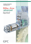
2.2.1. High resolution analog reference (optional)
Putting C09 = 0 (with the optional hardware) an analog signal can be provided ±of 10V that will be
converted into frequency while impulse counting will be taken from the high precision speed
reference. Parameter P10 permits compensation of any offset present in the analog input and is
expressed in units of 10μV;
Parameter P88 permits setting of the voltage
to which maximum speed will correspond
(default value of 10000mV or 10V).
REF2
100%
-P88
P88
-100%
1 / 10
Rev. 1.7 08.06.09
Vin
Standard closed loop application
OPEN DRIVE
2.2.2. Frequency reference
Two working modes can be selected with C09 :
o Setting C09 = 1 a reference can be provided with an encoder signal with 4 tracks of a
maximum range varying between 5V and 24V and a maximum frequency of 300KHz.
o Setting C09 = 2 a speed reference can be provided with an frequency signal with a
maximum range varying between 5V and 24V and a maximum frequency of 300KHz.
(setting C09 =3 will be manage the same input, but internally will be count only rising edge, this
option is useful only if it is used the time decode, see par. 2.2.3)
The number N of impulses/revolution for the reference is set by connection C39:
N° of
impulses/revolution
0
disable
1
64
2
128
3
256
4
512
5
1024
6
2048
7
4096
8
8192
9
16384
There are the parameters P11 and P12 that permit specification of the ratio between the reference
speed and input frequency as a Numerator/Denominator ratio.
In general terms, therefore, if you want the speed of rotation of the rotor to be x rpm, the
relationship to use to determine the input frequency is the following:
f=
x × N pulses/revolution × P12
60 × P11
and vice versa
x=
f × 60 × P11
N pulses/revolution × P12
Let us now look at a few examples of cascade activation (MASTER SLAVE) with frequency input
according to a standard encoder.
By a MASTER drive the simulated encoder signals A,/A,B,/B are picked up to be taken to the
frequency input of the SLAVE. By means of parameters P11 and P12 the slipping between the two
is programmed.
MASTER
N° of pulses/revolution = 512
P65 = 2500 rpm
SLAVE
N° of pulses/revolution = 512
P65 = 2500 rpm
P11=P12=100
The SLAVE goes at the same speed as the MASTER
MASTER
N° of pulses/revolution = 512
P65 = 2500 rpm
SLAVE
N° of pulses/revolution = 512
P65 = 2500 rpm
P11=50 P12=100
The SLAVE goes at half the speed of the MASTER
MASTER
SLAVE
N° of pulses/revolution = 512
N° of pulses/revolution = 512
P65 = 2500 rpm
P65 = 2500 rpm
To obtain good performance at low
Speed it is necessary to select an encoder
resolution
for the MASTER that is sufficiently high.
P11 =100 P12=50
The SLAVE goes at double the speed of the MASTER
1 / 11
Rev. 1.7 08.06.09
Standard closed loop application
OPEN DRIVE
2.2.3. Time decode of frequency input
The speed reference in pulses is very accurate (no pulses is lost) but for its nature it has an irregular
shape because are counted the edges every sampling period (TPWM) and this produce a speed
reference with many noise. Also if the frequency input is constant, between a PWM period and
another could be counted a variable number of pulses, ± one pulse. This produce a low resolution
reference, expecially when the frequency input decreases.
For not use a big filter with frequency reference it’s possible to use its time decode that has a good
resolution. It is measured the time between various edges of frequency input with resolution of
25ns, reaching a percentage resolution not less than 1/8000 (13 bit) working to 5KHz of PWM
(increasing PWM resolution decreases linearly).
It is produced the speed reference as percentage of maximum speed, knowing the pulses per
revolution in input and the transformation ratio P11 over P12.
Following the time decode there is a first order filter with time constant set in milliseconds into
parameter P48 and a proportional gain imposed with parameter P49 as percentage.
C 0 9 Inp ut configuration
1 = d igital en cod er
2 = freq u en cy/sign
3 = freq u en cy/sign 1 ed ge
O ther speed references (analog and d igital)
P11
2 16
BASE
E ncod er
Inp ut
C 39
Input p ulses
0=no
1=64
2=128
3=256
4=512
NUM
DEN
P12
C 7 0 o I18
T im e
d eco d e
+
+
τ = P 48 P 4 9
S peed reference
(“f_tem po ”)
S p eed refrence
(“f_ som m a_to t”)
5=1024
6=2048
7=4096
8=8192
9=16384
If the input is a frequency/sign reference it’s very important to set C09=3 because only counting the
rising edge it will be possibile to measure the time between one pulse and the other, and not the
pulse width.
The speed reference obtained could be used as in sum with the other analog and digital references.
(see par. 2.1).
In the follow paragraph it is explain how to use frequency input decoded in time within the pulses
reference in a electric axis.
1 / 12
Rev. 1.7 08.06.09
Standard closed loop application
OPEN DRIVE
2.2.3.1. Electric axis with frequency reference decoded in time
Manage a frequency position reference meaning ensure every time the correct phase between
master and slave. For obtain this result can be used the time decode of frequency input for giving
the speed reference in feed-forward, enabling the overlap position loop to ensure the
synchronization in phase between master and slave.
Set:
CON
C43 e I19
C52 e I14
C70 o I18
DESCRIPTION
VALUE
to set
0
0
1
Enable speed reference in frequency
Enable references from Fieldbus
Enable Speed reference frequency input
decoded in time
MEANING
Not enable
Not enable
Enable
With this configuration there is the follow control scheme:
O ther analo g and d igital speed reference
C 0 9 Input co nfiguration
R am p s
1 = d igital en cod er
(2 = freq u en cy/sign
3= freq u en cy/sign 1 ed ge
+
T im e
deco de
τ = P 48 P 4 9
P 11
2 16
BASE
E ncod er
Inp ut
C39
P ulses in input
0=no
1=64
2=128
3=256
4=512
5=1024
6=2048
7=4096
8=8192
9=16384
+
+
S p eed ref
(“f_ som m a_ tot”)
T o tal sp eed
reference
+
A P P L IC A T IO N
NUM
DEN
CORE
P12
+
Increm ental
P o sitio n ref
(“theta_ rif_p o s”)+
+
C 9 1 o I25
C 6 5 o I17
+
-
Increm ental
p osition
+
Z -1
P38
O v erlap P o sitio n loo p
O ther analo g and
d igital sp eed
reference
The speed reference in time (“f_somma_tot”) has a good resolution also for low frequency in input,
allowing to have high gains in speed regulator.
The overlap position loop has to be enabled setting C65=1 or I17=H, after that no pulse will be lost
and it will be ensure the correct phase between master and slave.
When the overlap position loop works it’s useless enable the ramps in speed reference decoded in
time.
It’s possible to add an offset to the position reference, setting C91=1 or I25=H. The offset is equal
to the sum of the other analog and digital speed reference enabled.
1 / 13
Rev. 1.7 08.06.09
Standard closed loop application
OPEN DRIVE
2.3. Multiplicative factor on speed reference
This function enables a multiplicative factor, depending on analog input, on speed reference.
It’s possible to choose the input for the multiplicative factor using C93 connection:
C93
0
1
2
3
4
Multiplicative factor input
None
AI1
AI2
AI3
AI16
With C94 connection, it’s possible to choose the speed reference that will be multiply by the factor:
C94
0
1
2
3
Speed ref. multiplied
None
AI1+AI2+AI3 (if configurated)
AI16
NUM electrical gear
With parameters P182 e P183 it’s possible to choose the percentage variation of the speed reference
corresponding to ± 10V of multiplicative factor input.
P182
200%
Example:
Multiplicative factor
P182=200%
P183=30%
100%
P183
70%
-10V
Multiplicative factor input
1 / 14
Rev. 1.7 08.06.09
+10V
Standard closed loop application
OPEN DRIVE
2.4.
Torque feed-forward on speed reference
It’s possible to enable the Torque feed-forward on speed reference using C90 connection:
C90
Mode of working
0
Not enabled
1
“f_somma_tot” speed reference derivative (analog a/o Fieldbus)
2
“theta_precision” speed reference derivative (analog to frequency,
frequency or from Fieldbus)
It’ possible to estimate the torque reference needing for the speed variation requested with the speed
reference derivative using a II° order filter (time constant in P180 in ms) and taking account of total
inertia (setting parameter P181 Startup time).
f_somma_tot
[ % maximum speed]
o42
1
C90
+
2
theta_precision
t_rif
Z -1
-
τ = P180
P181
[ % Nominal motor torque]
[Electrical pulses per Tpwm]
The Startup time is the time necessary for motor and load to reach the maximum speed (set in P65)
with the nominal motor torque. This data has to be set in milliseconds in parameter P181.
It’s useful to set some milliseconds of filter (P180) on order to avoid too much noise on torque
reference for the time derivative.
When it’s enabled this function the torque reference “t_rif” cannot be impose using the analog and
digital references see before.
The torque feed-forward can be very useful in the servo-drive application when the target is to
follow very promptly the speed reference, because it increases the bandwidth without using high
gains on speed regulator.
Note 1: for understand if the torque compensation is correct it’s useful to compare it with the total
torque reference from speed regulator. The internal monitoring variables are o42 for feed-forward
term and o5 for the final torque reference.
Note2: torque feed-forward isn’t appropriate in load variable inertia applications.
1 / 15
Rev. 1.7 08.06.09
Standard closed loop application
OPEN DRIVE
2.5. Speed regulator second parameters bank
This function is used to change on-line the speed regulator parameters (P31÷P33), the maximum
speed (P65) and the linear ramps acceleration times (P21÷P24), to achieve a good reference
resolution, working at low speed.
For enable the second parameters bank (P184÷P187) it’s necessary to set the connection C95=1,
otherwise to bring at high level the logical function I26 using one of the 8 logical inputs.
When the function is activated the standard data (P31÷P33, P65 and P21÷P24) are automatically
exchanged with the second bank (P184÷P191) and the connection C95 is set to 1.
I26 L Æ H
Speed regulator
Maximum speed
P65
P184
Proportional gain Kp
P31
P185
Lead time constant Ta
P32
P186
Filter time constant Tf
P33
P187
CW acceleration time CW
P21
P188
CW deceleration time CW
P22
P23
P24
P189
CW acceleration time CCW
CW deceleration time CCW
P190
P191
I26 H Æ L
The exchange will be executed only if the working speed is lower than the new maximum speed,
this is useful to avoid the over speed alarm A09.
If the speed is greater than new maximum speed, the activation command is ignored.
If the speed ramps are active your value will be automatically calculated to avoid sharp transitory.
The connection C95 keep memory of second parameters bank activation. When the drive is
switched on, the connection C95 and the logical input I26 are tested: if there is coherence no action
is taken, otherwise the connection C95 is automatically changed to line up with logical input I26
and the data are exchanged.
When the function is disabled, bringing I26 to low level or clearing C95=0, data are automatically
exchanged, with initial value restore.
1 / 16
Rev. 1.7 08.06.09
Standard closed loop application
OPEN DRIVE
3. Analog outputs management
There can be a maximum of two analog outputs, VOUTA and VOUTB ± 10 V, 2mA.
To each of the two outputs can be associated an internally regulated variables selected from the list
here below; the allocation is made by programming the connection corresponding to the output
concerned, C15 for VOUTA and C16 for VOUTB, with the number given in the table below
corresponding to the relative quantities. By means of the parameters P57 (for VOUTA) and P58
(for VOUTB) it is also possible to set the percentage of the variables selected to correspond to the
maximum output voltage (default values are P57=P58=200% so 10V in output correspond to 200%
of variable selected). The default for VOUTA is a signal proportional to the current supplied by
converter (C15=11), in VOUTB the signal is proportional to the working speed (C16=4).
It is also possible to have the absolute internal variable value desired: to do this it is simply
necessary to program the connection corresponding to the denied desired number: for example
taking C15=-21 there will be an analog output signal proportional to the absolute value of the
working frequency.
It is also possible to have a analog output fixed to +10V: to do this it is simply necessary to program
the connection corresponding to 64.
POSSIBLE CONNECTIONS
1
VOUTA
11
C15
100Ω
64
0
4
VOUTB
C16
100Ω
64
THE DARKER LINE INDICATES THE
DEFAULT PROGRAMMING
NORMALISED BASE INTERNAL VARIABLES FOR ANALOG
OUTPUTS
O 00
Actual mechanical position read by the sensor
(if the sensor has more than 2 poles it regards the current revolutio
sector)
O 01
Actual electrical position read by the sensor (delta m)
O 02
Reference speed after the ramp
O 03
Output reference speed from the torque regulator
O 04
Speed of rotation (filtered Tf= 8×TPWM , 1,6ms at 5KHz)
O 05
Torque requirement
100%=180° (with 2 poles)
100% = semi-sector ( +
poles)
100%=180°
% n MAX
% n MAX
% n MAX
% C NOM MOT
32767
32767
16383
16383
16383
4095
O 07
O 08
O 09
Torque current requirement at current loop
Flow current requirement at current loop
Voltage requirement at maximum revolutions
% I NOM AZ
% I NOM AZ
% VNOM MOT
4095
4095
4095
O 11
O 12
Current module
Zero top
% I NOM AZ
100%=180°
4095
32767
1 / 17
Rev. 1.7 08.06.09
Standard closed loop application
OPEN DRIVE
O 13
U phase current measured
% I MAX AZ
4095
O 15
O 16
O 17
O18
O19
O20
O21
O22
Torque component of measured current
Magnetising component of current measured
Duty-cycle U phase voltage
Reference stator ground voltage module
Modulation index
Q axis voltage requirement (Vq_rif)
Power supplied
D axis voltage requirement (Vd_rif)
% I NOM AZ
% I NOM AZ
% VNOM MOT
0⇔1
% VNOM
% PNOM
% VNOM
4095
4095
32767
4095
4095
4095
4095
4095
O24
O25
O26
O27
O28
O29
O30
O31
Bus voltage
Measured radiator temperature
Measure motor temperature
Rotor flux
Motor thermal current
Current limit
CW maximum torque
CCW maximum torque
100%=900V
% 37.6°
% 80°
% φ NOM
% A6 action threshold
% I MAX AZ
% C NOM MOT
% C NOM MOT
4095
4095
4095
4095
4095
4095
4095
4095
O34
O35
O36
O37
O38
O39
O40
O41
O42
O43
O44
O45
O46
O47
O48
O49
O50
O51
O52
o53
÷
o63
o64
Measured phase V current
Measured phase W current
Actual electrical position (alfa_fi )
Analog input A.I.1
Analog input A.I.2
Analog input A.I.3
Analog input A.I.16
Total speed reference (f_somma_tot)
Total torque reference (t_rif) for the application
Total torque limit reference (limit_i_aux)
Total speed reference (theta_precision)
Reference for overlapping position loop (theta_rif_pos)
Amplitude at square of sine and cosine feedback signals
Sen_theta (Direct resolver and Sin/Cos Encoder)
Cos_ theta (Direct resolver and Sin/Cos Encoder)
Unfiltered speed of rotation
Delta pulses on PWM period from frequency input
Lsw memory space error (overlapped position loop)
Msw memory space error (overlapped position loop)
----- Reserved for special applications -----
% I MAX AZ
% I MAX AZ
100%=180°
100%=16383
100%=16383
100%=16383
100%=16383
% n MAX
% C NOM MOT
% C NOM MOT
Pulses per Tpwm
Pulses per Tpwm
1=100%
Max amplitude = 200%
Max amplitude = 200%
% n MAX
Pulses per Tpwm
Electrical pulses
Electrical turns
4095
4095
32767
16383
16383
16383
16383
16383
4095
4095
1
1
32767
16383
16383
16383
1
1
1
see special application enclosure
Output fixed to +10V
1 / 18
Rev. 1.7 08.06.09
Standard closed loop application
OPEN DRIVE
4. Input logic management
The control requires up to 8 optically insulated digital inputs (L.I.1 … L.I.8.) whose logic functions
can be configured by means of connection C1 ÷ C8.
The following table shows the logic functions managed by standard application:
INPUT LOGIC FUNCTIONS
I
I
I
I
I
I
I
I
I
I
I
I
I
I
I
I
I
I
I
I
I
I
I
I
I
I
I
I
00
01
02
03
04
05
06
07
08
09
10
11
12
13
14
15
16
17
18
19
20
21
22
23
24
25
26
29
Run command
Torque control
External consent
Enable 14 bit analog reference A.I.1.
Enable 14 bit analog reference A.I.2.
Enable speed jog
Enable digital potentiometer speed reference
Enable 14 bit analog reference A.I.3.
Alarms reset
UP digital potentiometer
DOWN digital potentiometer
Load last digital potentiometer value
Reversal reference
Enable power soft-start
Enable FIELD-BUS references
Enable Φ external flux (only in the DVET)
Activation second bank of parameters
Enable space loop for electrical axis
Enable time decode speed reference in frequency
Enable speed references in frequency
Enable 16 bit speed reference (if present)
STOP command (locked run )
Enable line ramps
Motor termo-switch
Freeze PI speed regulator integral memory
Enable offset on overlap position loop reference
Enable second bank speed regulator gains
--- Reserved for special applications ----
I
63 see special application enclosure
DEFAULT
INPUT
L.I.4
L.I.2
L.I.3
L.I.5
L.I.7
L.I.1
L.I.6
DEFAULT
STATUS
L
L
H
L
L
L
L
L
L
L
L
L
L
H
L
L
L
L
L.I.8
L
L
L
L
L
L
L
L
NB: pay particular attention to the fact that it is absolutely not possible to assign the same
logic function to two different logic inputs: after changing the connection value that sets a
determined input, check that the value has been accepted, if not check that another has not
already been allocated to that input. In order to disable a logic input it’s necessary to assign to
it the logic function -1 : this is the only value that can be assigned to more than one inputs.
For example, to assign a specific logic function to logic input 1 you must first write the desired
logic number for connection C01 :
C01 = 14 Æ logic input 1 can be used to enable Fieldbus references
The logic functions that have been configured become active ( H ) when the input level is at high
status (20V < V < 28V), and there is a 2.2ms hardware filter. With the connection C79 it’s possible
to enable the active logic low state for a particular digital input, it’s necessary to sum 2 to the power
of ordinal input number:
For example to set digital inputs I0 and I3 to active low state, set:
1 / 19
Rev. 1.7 08.06.09
C79 = 2 0 + 2 3 = 9
Standard closed loop application
OPEN DRIVE
The functions that have not been assigned assume default value ; for example, if the function
“external enable“ is not assigned it becomes, as default, “active ( H )” so the converter is as if there
were no assent from the field.
4.1.1. Input logic functions set in other ways
In reality the input logic functions can also be set by serial connection and by fieldbus, with the
following logic:
o
o
o
I00 Run = stands alone, it has to be confirmed by terminal board inputs, by the serial and by
the fieldbus, though in the case of the latter the default is active and so, if
unaltered, controls only the terminal board input.
I01÷ I28 = is the parallel of the corresponding functions that can be set at the terminal
board, the serial or the fieldbus.
I29 ÷ I63 = only the functions reserved for special applications, they can certainly be
changed by suitably configuring the terminal board inputs, and other possibilities
can be attributed by the application itself.
4.1.2. Locked Run from terminal board
It may be a matter of interest that the RUN command can be given by the commutation edge from a
low to high signal: to enable this function set C53=1.
In this operational mode the STOP command is also used ( I21, after having configured one of the
logic inputs) which is level sensitive:
- low level: converter in STOP, power disabled
- high level: the converter can be at RUN
The diagram below shows the working logic:
STOP
(I21)
H
L
RUN
(I00)
H
L
EFFECTIVE
RUN
COMMAND
H
L
• The RUN command is only given if there
is a risign edge L->H on I00 with I21
high.
• Once RUN has been give to logic input
I00 can return to low level
• As soon as the STOP signal (I21) goes to
low the RUN command is switched off
• If the converter goes into an alarm state
the run command will be switched off
and so it will be necessary to repeat the
start up procedure as soon as the
converter is ready again.
1 / 20
Rev. 1.7 08.06.09
OPEN DRIVE
Standard closed loop application
5. Logic outputs management
The control can have up to 4 optically insulated digital outputs (L.O.1 … L.O.4) whose logic
functions can be configured as active high (H) by means of connection C10 ÷ C13.
The following table shows the logic functions managed by standard application:
OUTPUT LOGIC FUNCTIONS
O
O
O
O
O
O
O
O
O
O
O
O
O
O
O
O
O
O
O
O
O
00
01
02
03
04
05
06
07
08
09
10
11
12
13
14
15
16
17
19
20
21
o
31
Drive ready
Thermal motor alarm
Speed above minimum
Run drive
CW / CCW
Current/torque relay
End of ramp
Current limit drive
Torque limit drive
Incremental position error > threshold (P37 ane P39)
Switch on power soft-start
Braking active
No supply mains
Bus regeneration activated (Support 1 )
Motor thermal current above threshold (P96)
Radiator temperature too high (above threshold P120)
Speed reached (above absolute value at P47)
No supply main to Power electronic card
Regulation card supplied and DSP not in reset state
DC Bus above threshold (P177)
----- Reserved for special application -----
DEFAULT
OUTPUT
L.O.2
L.O.4
L.O.1
L.O.3
see special application enclosure
If you wish to have the logic outputs active at the low level (L) you need just configure the
connection corresponding to the chosen logic function but with the value denied: for example, if
you want to associate the function “ end of ramp ” to logic output 1 active low, you have to
program connection 10 with the number -6 ( C10=-6 ).
Note: if you want to configure Output logic 0 to active low you have to set the desired connection to
value -32
1 / 21
Rev. 1.7 08.06.09
OPEN DRIVE
OPEN DRIVE
Common functions
Common functions
OPEN DRIVE
INDEX
1
2
3
4
5
6
7
8
Storage and recall of the working parameters ............................................................................. 2
Voltage break control for mains feeding...................................................................................... 3
2.1
Continuing to work (C34=0; default) .................................................................................. 3
2.2
Recovery of Kinetic Energy (C34=1) .................................................................................. 4
2.3
Overcoming mains breaks of a few seconds with flying restart (C34=2)........................... 4
2.4
Emergency brake (C34=3) ................................................................................................... 5
Braking management ................................................................................................................... 6
3.1
Recovery mains energy ........................................................................................................ 6
3.2
Braking with DC Bus control (C47=1) ................................................................................ 7
3.3
Kinetic energy dissipation on breaking resistance ............................................................... 7
3.3.1
Braking Resistance Thermal protection ....................................................................... 8
Power soft start........................................................................................................................... 10
4.1
Safety Stop ......................................................................................................................... 11
4.1.1
Machine safety (C73=0) ............................................................................................ 11
4.1.2
Power part enable input (C73=1) ............................................................................... 11
Sequences of drive switch on and switch off ............................................................................. 12
5.1
Drive ready......................................................................................................................... 12
5.2
Drive switch on / RUN ...................................................................................................... 12
5.3
Drive switch off / STOP .................................................................................................... 12
Thermal protections hardware ................................................................................................... 13
6.1
Thermal protection drive .................................................................................................... 13
6.2
Motor thermal protection ................................................................................................... 13
Current/power relay ................................................................................................................... 14
Active bank parameters .............................................................................................................. 14
2/1
08.06.2009
Common functions
OPEN DRIVE
The standard functions of the OPEN DRIVE are common to all versions of the product.
1
Storage and recall of the working parameters
The drive has three types of memory:
1. The non permanent work memory (RAM), where the parameters become used for operation
and modified parameters become stored; such parameters become lost due to the lack of
feeding regulation.
2. The permanent work memory (FLASH), where the actual working parameters become
stored to be used in sequence (C63=1, Save Parameters on FLASH).
3. The permanent system memory where the default parameters are contained.
When switched on, the drive transfers the permanent memory parameters on to the working
memory in order to work. If the modifications carry out on the parameters, they become stored in
the work memory and therefore become lost in the break of feeding rather than being saved in the
permanent memory.
If after the work memory modifications wants to return to the previous security, it is acceptable to
load on such a memory, a permanent memory parameter (Load FLASH Parameter C62=1).
If for some reason the parameters in FLASH change, it is necessary to resume the default
parameters (C61=1 Load Default Parameters), to make the appropriate corrections and then save
them in the permanent working parameter (C63=1).
It is possible to save the data in the permanent memory also at drive switched on/RUN, while the
loading may only be affected aside with drive switched off/STOP, after having opened the key to
reserved parameters.
Restore the default parameters
System permanent
memory with default
parameters (FLASH)
Non permanent
memory (RAM)
C61=1
Save parameters in FLASH
C63=1
C62=1
Permanent memory
(FLASH)
Reading
parameters and
connections at start
up
Loading the FLASH
parameters
Because the default parameters are standard to be different than those that are
personalized, it is correct that after the installation of each drive, there is an
accurate copy of permanent memory parameters to be in the position to
reproduce them on an eventual drive exchange.
2/2
08.06.2009
Common functions
OPEN DRIVE
2 Voltage break control for mains feeding
The mains break control is configurable through the following connections:
Connection
C34
C35
Significance
Mains break out control
0= continuing to work; 1= recovery of Kinetic Energy; 2= free; 3=
emergency brake
Alarms automatically reset when the mains return
2.1 Continuing to work (C34=0; default)
This operating procedure is adapted to those applications in which it is fundamental to have
unchanged working conditions in each situation. Setting C34=0 the drive, even if the mains supply
voltage is no longer available, continues to work as though nothing has been modified over the
control, pulling the energy from the present capacitor to the inner drive. This way making the
intermediate voltage of the DC Bus will begin to go down depending on the applied load; when it
reaches the minimum tolerated value (in parameter P106) the drive goes into alarm A10 of
minimum voltage and leaves to go to the motor in free evolution.
Therefore, this function will allow exceeding short-term mains break out (tenths/hundredths of
milliseconds on the basis of the applied load) without changing the motor operation in any way.
DC bus voltage
540V
speed
400V
Minimum voltage
allowed (P106)
C34=0
Continue to work
Break
mains
Return
mains
time
If the alarm condition starts, there is the possibility to enable, setting C35=1 the alarms to an
automatic reset at the mains restore.
2/3
08.06.2009
Common functions
OPEN DRIVE
2.2 Recovery of Kinetic Energy (C34=1)
This operating procedure is adapted to those applications in which it is temporarily possible to
reduce the speed of rotation to confront the mains break. This function particularly adapts in the
case of fewer applied motors and with high energy.
The qualification of such a function is obtained setting C34=1.
During the mains break out, the voltage control of the DC Bus is achieved using a proportional
regulator, with fixed proportional gain set in P86 (default=3.5), that controls the DC Bus voltage
d24, compare it with the threshold in P98 (default=600V) and functions on the torque limits d30 of
the motor that, in time, will slow down to work in recovery. Such regulation, when qualified
(C34=1), at mains break out (o.L.12=H) or if the DC Bus voltage goes below the threshold set in
P97 (425V), replaces the normal regulation (o.L.13=H) and is excluded when mains supply is on.
DC bus voltage
540V
speed
Minimum voltage
allowed (P106)
400V
C34=1
Recovery of Kinetic Energy
Break
mains
Return
mains
time
If the alarm condition starts, there is the possibility to enable, setting C35=1 the alarms to an
automatic reset at the mains restore.
2.3 Overcoming mains breaks of a few seconds with flying restart
(C34=2)
This operating procedure is adapted to those applications in which it is fundamental to not go into
alarm in the case of mains break out and is temporarily prepared to disable the power in order for
the motor to resume when the mains returns.
The qualification of such a function is obtained setting C34=2.
When there is a mains break or if the voltage of the Bus goes below the threshold set in P97r (425
V), the drive is immediately switched off, the motor rotates in free evolution and the Bus capacitors
slowly discharges. If the mains returns in a few seconds, a fast recovery of the motor is carried out
in a way in which the working regulation of the machine is resumed.
2/4
08.06.2009
Common functions
OPEN DRIVE
DC bus voltage
540V
speed
400V
Minimum voltage
allowed (P106)
C34=2
Free motor
Time of soft start
Return
mains
Break
mains
time
At the return of the mains, it will need to wait for the time of soft start for the gradual recharging of
capacitors for the motor to be able to resume.
2.4 Emergency brake (C34=3)
This particular control is adapted to those applications in which the machine may be stopped with
an emergency brake in case of mains breaks.
Under this circumstance, the linear ramps becomes qualified and the ramp time is imposed with the
parameter P30. When the minimum speed is reached, alarm A10 of minimum voltage starts and the
motor is left rotating in free evolution. If in the meantime the mains returns, the emergency brake
will be not interrupted.
DC bus voltage
540V
C34=3
Emergency brake
speed
Minimum speed (P52)
Break
mains
Return
mains
2/5
08.06.2009
time
Common functions
OPEN DRIVE
3 Braking management
The drive is in a position to work on four quadrants, therefore is also in a position to manage the
motor recovery Energy. There are three different, possible controls:
3.1 Recovery mains energy
To be able to restore the kinetic Energy into the mains, it is necessary to use another OPEN drive ,
specifically the AC/DC Active Front End (AFE). A Power Factor Controller deals with the
position to have a power factor close to unity. Specific documentation is sent back from specific
details. This solution is adapted to those applications in which the additional cost justifies another
drive with a lot of energy that is recovered in the mains or for particular thermal dissipation
problems in the use of a braking resistor.
U
V
W
Mains
Inductor
AC/DC
AFE
+
+
-
-
OPEN drive
Drive
U
V
W
Motor
OPEN drive
The use of an AC/DC AFE permits a controlled voltage level of the intermediate power (DC Bus)
and raises to best control the motors winded to a voltage close to the line voltage. The drive’s
dynamic behavior results in a way that optimizes the work as motor or generator.
There is a possibility to connect more than one drive to the DC Bus, with the advantage of energy
exchange between drives in case of contemporary movements and only one energy exchange with
the mains.
DC bus voltage
Recovery of mains energy
speed
time
2/6
08.06.2009
Common functions
OPEN DRIVE
3.2
Braking with DC Bus control (C47=1)
A further possibility of recovery control of kinetic energy exists: if the outer braking resistance is
not present (or is not working properly), it is possible to enable (setting C47=1) the braking with
DC Bus control. This function, when the Bus voltage reaches the threshold set in P123, limits the
maximum admitted regenerated torque, slowing down the motor. In practice, the motor will slow
down in minimum time thus the over voltage alarm does not start.
This function is not active by default (C47=0) in a way to leave the intervention of the braking
circuit.
P123
DC bus voltage
Controlled braking of the DC
Bus
speed
3.3 Kinetic energy dissipation on breaking resistance
The standard solution for the OPEN drive is the dissipation of kinetic Energy on braking resistor.
All the OPEN drives are equipped with an eternal braking circuit, while the braking resistor must be
connected externally, with the appropriate precautions.
With this solution, the Bus’ maximum level of voltage becomes limited through a power device that
connects in parallel the resistor with the DC Bus capacitors, if the voltage exceeds the threshold
value in P108, the drive keeps it inserted until the voltage goes below the value of P109; in such a
way, the energy that the motor transfers onto the DC Bus during the braking, is dissipated from the
resistor.
This solution guarantees good dynamic behavior also in braking mode.
In the follow figure it’s shown the Bus voltage and the speed during a dissipation on breaking
resistance.
2/7
08.06.2009
Common functions
OPEN DRIVE
P108
DC bus voltage
P109
Energy dissipation on
breaking resistor
speed
A maximum voltage limit allowed exists for the DC Bus voltage. This is checked by the software
(threshold P107), and by the hardware circuitry: in case the voltage exceeds this level, the drive will
immediately go into an over voltage alarm A11 to protect the internal capacitors.
In case of A11 alarm condition starts, verify the correct dimensioning of the braking resistor power.
Refer to the installation manual for the correct dimensioning of the outer braking resistor.
The braking resistor may reach high temperatures, therefore appropriately
place the machine to favor the heat dissipation and prevent accidental
contact from the operators.
3.3.1 Braking Resistance Thermal protection
The Braking Resistance Thermal protection protects the resistance both from Energy peaks and
from average Power that have to be dissipated.
It’s possible to enable this protection setting C72=1, by default this function is disabled.
Instantaneous Power: the quickly Energy exchange is an adiabatic process since heat diffusion on
case resistance is very slow, in the meantime the resistance is dimensioning for a maximum energy
overload. This protection is based on the follow parameters:
PAR
P167
P168
P169
DESCRIPTION
Braking resistance value
Braking resistance Maximum Adiabatic Energy
Time to test the Maximum Adiabatic Energy
RANGE
DEFAULT
UNIT
1 ÷ 1000
0.0 ÷ 500.0
1 ÷ 30000
82
4.5
2000
Ohm
KJoule
ms
Internal
rappr.
1
10
1
After the first Braking resistance activation, the dissipated Energy is accumulated, knowing the DC
bus voltage, the Braking resistance value and the activation time.
This accumulation is done for a time set in milliseconds in P169 parameter: if in this period the
Energy becomes greater than maximum threshold ( set in KJoule into P168 parameter) the control
disables the Braking resistance. At that point, if it is enables the braking with DC Bus control
(C47=1, see par.3.2) it starts to work, otherwise the alarm A4 code d49=1 (Instantaneous Power
Braking Resistance) becomes active.
2/8
08.06.2009
Common functions
OPEN DRIVE
At the end of every accumulation period it is possible to show the total dissipated Energy on the
period in KJoule in the internal value d39, than can start a new period, the Braking resistance is
enabled again and the speed reference is aligned with the real speed.
NB: this function has two possible uses:
It takes the converter in alarm if the Instantaneous Power is too high (C47=0)
It is possible to choose how many Energy could be dissipated on Braking resistance and in
the remaining time braking with the DC Bus control (C47=1). With P169=1000ms it is
possible to set in P168 the Power in KWatt that could be dissipated on the resistance. In
the follow figure is shown an experimental measurement of this function:
Vbus
P169
Speed
reference
Speed
regulated
Average Power: the Energy dissipated every PWM period is used to estimate the average Power
dissipated on Braking Resistance. The parameters used are:
PAR
P167
P170
P171
DESCRIPTION
Braking resistance value
Braking Resistance Maximum Average Power
Average Power Filter time constant
RANGE
DEFAULT
UNIT
1 ÷ 1000
1 ÷ 30000
1 ÷ 2000
82
150
720
Ohm
Watt
s
Internal
rappr.
1
1
1
Every second the total dissipated Energy is equal to the Average dissipated Power.
This value is filtered with a first order filter with a time constant set in seconds in P171 (the time
constant depends on Braking Resistance thermal characteristics). In P170 parameter is possible to
set the maximum average power. In the internal value d38 it’s possible to see the Average
Dissipated Power in Watt, if this value becomes greater than the threshold P170 the alarm A4 code
d49=2 (Average Power Braking Resistance) becomes active.
2/9
08.06.2009
Common functions
OPEN DRIVE
4 Power soft start
The bridge rectifier build in the drive may be uncontrolled (diode) or semi-controlled (up to OPEN
40 it is uncontrolled). If the diode bridge is implemented, the power soft start function acts
bypassing a soft start resistor (in series with the output of the power bridge), after the DC Bus
Voltage has charged; otherwise the same function unblocks the semi-controlled input power bridge
permitting the gradual charge of the DC Bus voltage and supplying the drive feeding for the
following work.
N.B: It is fundamental to correctly set up the connection C45 build in Power
Bridge : 0= uncontrolled (diode) ; 1 = semi-controlled
The function becomes active if the entry functions are active “Enable soft start” I.13, and the
connection C37 (C37=1) and the presence of mains supply voltage becomes noticed, with the
following logic:
Mains supply presence: in case the presence of alternated mains supply voltage becomes noticed
once (at soft start) with the logic power input MAINS_OFF=H, from that moment the control
refers only to the MAINS_OFF to check the mains presence. Otherwise, in the case of drive
feeding with a continuous direct voltage on the DC Bus, it is possible to begin the soft start, even if
the measured voltage on the DC Bus exceeds the indicated value in P97.
Mains break out: the mains break becomes noticed either when the MAINS_OFF signal is
monitored (if this went to the high logic level at least one time during the soft start) either
monitoring directly the DC Bus voltage with minimum threshold setup in P97.
The function of “Soft start enable” may be assigned to one of the logic input thus to enable or
disable the soft start through an external contact.
The power fault alarm (power fault A03), that checks drive over current, insert the soft start limiting
current.
The soft start follows the following criteria:
I13
C37
A03
X
0
X
1
1
X
X
0
1
1
H
L
L
L
L
Mains
Presence
X
X
X
L
H
Soft start
enable
OFF
OFF
OFF
OFF
ON
oL10
L
L
L
L
H
From default PR.ON=1 and C37=1 thus connecting the drive to the mains supply, the power is
enable immediately with the soft charging of the capacitors.
The soft start charge of the intermediate circuit capacitors lasts a preset time set in P154, after this
time the voltage level is checked to verify the voltage level reached: if this is below the minimum
(P97), the soft start alarm starts.
The drive is not enabled to switch on if soft start function has not ended successfully.
2 / 10
08.06.2009
Common functions
OPEN DRIVE
4.1 Safety Stop
The OPEN drive converters have the possibility to give the separated IGBT supply, see Installation
manual. This supply voltage can be see like safety STOP input and there are two different
managements for this input, selectable with C73 connection:
For OPEN DRIVE versions with Safe Torque Off safety function (STO) according
to EN 61800-5-2 and EN 13849-1 see STO installation manual.
4.1.1
Machine safety (C73=0)
Setting C73=0 (default) the Safety STOP is compatible with EN945-1 specification against
accidental starts. When this input is at low logical level the IGBT power bridge isn’t supplied and
the motor couldn’t run more than 180°/motor poles couple for brushless motor (for asynchronous
motors the movement is zero), also if there is a brake in the power bridge.
The converter signals this state with the alarm A13 d49=1, the output o17 “Power electronic not
supplied” goes at high level, the output o0 “Drive ready” goes at low level and the Power Soft start
command is taken off.
To recover the normal converter state, follow this steps:
Give +24V to the IGBT driver supply input (Safety STOP). At this point the converter
goes at low level the output o17 “Power electronic not supplied”.
After 500ms the converter is able to start the Soft start sequence, like to see in par.4
Reset the converter alarms for eliminate the alarm A13.The normal converter state is
recovered.
4.1.2
Power part enable input (C73=1)
Setting C73=1 the Safety STOP is like a Power part enable input. Like in the preceding case,
when this input is at low logical level the IGBT power bridge isn’t supplied and the motor couldn’t
run more than 180°/motor poles couple for brushless motor (for asynchronous motors the
movement is zero), also if there is a brake in the power bridge.
The converter signals this state with the output o17 “Power electronic not supplied” that goes at
high level, the Power Soft start command is taken off, but unlike before no alarms goes at active
state. To recover the normal converter state, follow this steps:
Give +24V to the IGBT driver supply input (Safety STOP). At this point the converter
goes at low level the output o17 “Power electronic not supplied”.
After 500ms the converter is able to start the Soft start sequence, like to see in par.4, there
is an automatic alarm reset and the normal converter state is recovered.
In this case it isn’t necessary to reset the alarms after take back at high level the Safety STOP input,
it will be sufficient to wait 500ms + soft start time, after that the converter could be goes on run.
2 / 11
08.06.2009
Common functions
OPEN DRIVE
5 Sequences of drive switch on and switch off
5.1 Drive ready
The Drive Ready condition (o.L.0=H) is given by alarms are not active and at the same time both
the software and hardware enables:
* The software enable, given by state of the connection C29, (C29=1 of default).
* The external enable (the function of the input is assigned to the default input L.I.2)
If an enable is missing or an alarm is active, the ready drive signal goes into an non-active state
o.L.0=L and this state remains until the causes that brought about the alarm conditions are removed
and the alarms are reset. An alarm reset can be achieved by activating the function “Alarm reset”
that, by default, is assigned to input L.1 (or setting C30=1).
Keep in mind that the “Alarm reset” is achieved by the active front of the signal, not on the active
level.
5.2 Drive switch on / RUN
When the drive is “Ready to switch on / RUN” o.L.0=H, motor may start running “Drive switch
on/run” o.L.3=H, by activating both the hardware and software switch on enables:
* Function “Logic switch on/RUN input” (default input 4 assigned) RUN=H
* Software switch on/RUN C21 (C21=1) is active by default.
Switch on/RUN disable and enable (from STOP offline, to RUN online) is given by the logic of the
following table:
Drive ready
o.L.0
L
H
H
H
Switch on / RUN C21
ON-LINE
X
L
X
H
L
L
L
H
X
X
0
1
It is mentioned that the input function “Switch on/RUN input” can given also via serial line or fieldbus. See for details the Standard Application Manual.
5.3 Drive switch off / STOP
By default, the drive switch off instantaneously as soon as one of the switch on functions is disabled
(immediate shutdown); that may also cause an almost immediate rotation shutdown, if the motor is
loaded and the inertia is low, while coasting if the motor is without load and mechanical inertia is
high.
Using the connection C28, it is possible to choose to switch off the drive only with motor at
minimum speed. With C28=1, 0=immediate switch off by default, when SWITCH ON/RUN
function is disable, the speed reference is brought to zero, thus the motor starts to slowdown
following the ramp (the drive is still switched on). The system is switched off /STOP (offline) only
once the motor absolute speed goes below the threshold set in P50 (2.0% default), that is when the
motor is almost motionless (shutdown for minimum speed).
2 / 12
08.06.2009
Common functions
OPEN DRIVE
Calibrating P50 may coincide the drive block with the motionless motor. The state of speed above
the minimum is signaled from the logical output function o.L.2, moreover the output function
o.L.16 is available, that signals the drive speed (absolute value) is above the threshold speed level
P47. In every way, whichever is the chosen type of shutdown, there is an immediate drive block in
presence of any alarm condition, oL.0 = L.
6 Thermal protections hardware
Thermal probes are managed by the drive with the intent of protecting the drive itself and the motor
from damage.
6.1 Thermal protection drive
The drive is equipped with thermal probe in the heatsink that may be a PTC or a NTC depending on
the size of the drive. Setting the connection C57≠0 the thermal probe control is enabled. In this
case, it is possible to visualize the heatsink temperature in internal value d25, in degrees Celsius.
The following thresholds are foreseen:
o With the parameter P120 it is possible to set a temperature level above which the function
o15 “excessive radiator temperature” goes to a logic level high.
o If the temperature exceeds the maximum value setup in the parameter P118, the drive goes
into A4 d49=0 alarm “Thermal heatsink”
o If the measured temperature is above the threshold level set in parameter P119 and the RUN
command is switched on , the drive goes into A12 d49=2 alarm.
6.2 Motor thermal protection
The drive can manage the motor thermal probe. For the correct wiring of the probe, make reference
to the installation manual.
The connection C46 selects the type of probe used:
C46
Description
0
1
No motor thermal protection enabled
PT100 management : The motor’s temperature is measured
and compared to the maximum setup in parameter P91,
If the temperature exceeds the threshold, the A5 alarm starts.
PTC management: The thermal resistance is measured and
compared to the maximum setup in the parameter P95, If the
temperature exceeds the threshold, the A5 alarm starts.
NTC management: The thermal resistance is measured and
compared to the minimum setup in the parameter P95, If the
value is below, the A5 alarm starts.
2
3
4
Visualization
in d26
Termo-switch management: it’s possible to configure a logic input
to I23 function, in this case if this input goes to a low level the A5
alarm starts.
2 / 13
08.06.2009
Motor
temperature in
°C
Thermal probe
resistance in Ω
Thermal probe
resistance in Ω
------
Common functions
OPEN DRIVE
7 Current/power relay
The drive is in the position to control a logic output of current/power relay.
The connection C55 serves to select the type of monitored values:
C55
1
2
3
Description
Current : Current model referred to the motor’s nominal current
Torque of currents: refers to the torque of the motor nominal current
Power. Refers to the motors nominal power
The selected value is filtered with a first order filter with constant time setup in seconds in P27, and
then compared with threshold setup in the parameter P26; if it is greater, the high logic level brings
the logic function o.L.5 to the logic level high.
8 Active bank parameters
This function allows to switch over the internal sets of parameters and connections between two
distinct memory banks (drive must be switched off, no RUN).
To activate this function, it is necessary to use the logic input I16, configuring it on a logic input on
both banks. The connection C60 indicates the actual data bank in the permanent memory: C60=0
bank 0; C60=1 bank 1. The commutation of the functions logic stage I16 brings an automatic
variation of data of C60 and a successive automatic reading of data from the permanent memory.
C60
Indicates
the active
bank
RAM working
memory
Permanent memory
FLASH
Data bank 0
Data bank 1
On the front of commutation of I16
changes C60 and a reading from
FLASH is required
For initial configuration of the input function I16, follow these steps:
1. Prepare in RAM, the data in bank 0, configuring input function I16 and holding it to a
low logic level (make sure C60=0).
2. Save to the permanent memory with C63=1.
3. Always keep I16=L, prepare in RAM the data from bank 1, configuring the same input
to the function I16.
4. Set C60=1 and save the data in the permanent memory with C63=1.
5. At this point, changing the state of logic input corresponding to function I16, the
bank’s commutation will have automatic reading
2 / 14
08.06.2009
OPEN DRIVE
OPEN DRIVE
Brushless core
Brushless Core
OPEN DRIVE
“Brus” Brushless Core
INDEX
1.
Complete list of control values ............................................................................................ 2
1.1.
Parameters ........................................................................................................................ 2
1.1.1.
List of free parameters ..................................................................................................... 3
1.1.2.
List of reserved parameters .............................................................................................. 4
1.1.3.
List of TDE MACNO reserved parameters ..................................................................... 5
1.1.4.
Reserved parameters for specific applications ................................................................. 6
1.2.
Connections...................................................................................................................... 6
1.2.1.
Free connections .............................................................................................................. 6
1.2.2.
Reserved connections....................................................................................................... 7
1.2.3.
Reserved connections TDE MACNO .............................................................................. 8
1.2.4.
Reserved connections for specific applications ............................................................... 8
1.3.
Input logic functions ........................................................................................................ 8
1.4.
Internal values .................................................................................................................. 9
1.5.
Output logic functions.................................................................................................... 10
1.6.
List of alarms ................................................................................................................. 11
1.7.
List of internal values for monitors and analog outputs................................................. 11
2.
Setting basic parameters .................................................................................................... 13
2.1.
Auto-tuning parameters ..................................................................................................... 14
3.
Auto-tuning procedures ..................................................................................................... 15
3.1.
Sensor and motor pole tests ............................................................................................... 15
3.2.
Identifying models of brushless motor .............................................................................. 16
3.2.1. Test 1: Reading stator resistor drop ................................................................................... 17
3.2.2. Test 2: Learning the total leakage induction drop reported to the stator ........................... 17
4.
Regulation.......................................................................................................................... 18
4.1.
Choosing control type: speed or torque ............................................................................. 18
4.2.
Managing speed reference values ...................................................................................... 19
4.2.1. Inverting and limiting speed reference values ................................................................... 19
4.2.2. Linear and rounded ramps ................................................................................................. 20
4.2.3. Overlapped space loop ...................................................................................................... 21
4.3.
Speed and stability regulator ............................................................................................. 21
4.3.1. 2nd order speed regulator filter ......................................................................................... 22
4.3.2. Variable speed regulator gains .......................................................................................... 22
4.4.
Voltage regulation (flux weakening) ................................................................................. 23
4.5.
Current regulation .............................................................................................................. 24
4.6.
Choosing the active torque limit........................................................................................ 24
4.6.1. Maximum current limit...................................................................................................... 25
4.6.1.1. Drive thermal image .......................................................................................................... 25
4.6.1.2. Motor thermal protection ................................................................................................... 26
4.7.
Maximum speed limit on the basis of number of motor poles .......................................... 27
4.8.
IPP Initial Pole position detection ..................................................................................... 28
5.
Maintenance and controls .................................................................................................. 29
5.1.
Malfunctions without an alarm: troubleshooting .............................................................. 29
5.2.
Malfunctions with an alarm: troubleshooting.................................................................... 30
3/1
08.06.09
Brushless Core
OPEN DRIVE
The “Brushless core” controls the current or speed within a feedback vector AC brushless motor.
The speed and current reference values are generated by the application. See specific documentation
for further information. As an absolute position value is required for the sensors (managed with an
optional internal electronic board) incremental TTL Encoders with Hall effect sensors, Resolver,
absolute Sin/Cos Encoders and digital sensors as Endat and Hiperface may be used. However it’s
possible to use incremental sensor but every regulation power switch-on is necessary to execute the
IPP Initial Pole Position detection. See the “Feedback Option” file for information about
connecting the sensor correctly and the functional tests.
The “Brushless core” also manages the auto-tuning test, which is crucial if the control is to adapt
perfectly to the motor and to ensure excellent dynamic performance all-round.
1. Complete list of control values
1.1. Parameters
The parameters are drive configuration values that are displayed as a number within a set range.
The parameters are mostly displayed as percentages, which is especially useful if the motor or drive
size have to be changed in that only the reference values (P61÷P65) have to be modified and the
rest changes automatically. The parameters are split up into free, reserved and TDE MACNO
reserved parameters.
The following rules apply:
o
o
o
Free parameters: may be changed without having to open any key, even when running;
Reserved parameters (r): may be changed only at a standstill after having opened the
reserved parameter key in P60 or the TDE MACNO reserved parameters key in P99;
TDE MACNO reserved parameters (t): may be changed only at a standstill after having
opened the TDE MACNO reserved parameters key in P99. While the key for these parameters
is closed, they will not be shown on the display.
Hereunder is a complete list of bruhless control parameters.
Take careful note of the reference values for each parameter so that they are set correctly. The
penultimate column shows the internal representation base of the parameters. This value is
important if the parameters have to be read or written with a serial line or fieldbus.
Example1:
P7 = Speed jog
Normalization unit = % n MAX
Int. rep. base = 16383
Internal value = 4000 Æ real value = 4000/16383 = 24.4% of the maximum speed
Example1:
P62 = Rated motor BEMF
Normalization unit = Volt
Int. rep. base = 10
Internal value = 3800 Æ real value = 3800/10 = 380.0 Volt
The last column explains the parameter: a number refers to a paragraph in this file; letters refer to an
abbreviated name for the document to be consulted.
3/2
08.06.09
Brushless Core
OPEN DRIVE
1.1.1.
PAR
P01
P02
P03
P04
P05
P06
P07
P08
P09
P10
P11
P12
P13
P14
P15
P16
P17
P18
P19
P20
P21
P22
P23
P24
P25
P26
P27
P30
P31
P32
P33
P34
P37
P38
P39
P40
P42
P43
P44
P45
P46
P47
P48
P49
P50
P51
P53
P54
List of free parameters
DESCRIPTION
Range
Corrective factor for 14 bit analog reference 1 (AN_INP_1)
Corrective offset for 14 bit analog reference 1 (AN_INP_1)
Corrective factor for 14 bit analog reference 2 (AN_INP_2)
Corrective offset for 14 bit analog reference 2 (AN_INP_2)
Corrective factor for 14 bit analog reference 3 (AN_INP_3)
Corrective offset for 14 bit analog reference 3 (AN_INP_3)
Digital speed reference value (JOG1)
Motor potentiometer starting speed
Filter time constant for analog torque reference value
Offset for high precision analog reference value
NUM – Frequency input slip ratio
DEN – Frequency input slip ratio
Corrective factor for 16 bit analog speed reference value
Corrective offset for 16 bit analog speed reference value
Logic input I08 digital filter
Max. motor potentiometer speed reference value
Min. motor potentiometer speed reference value
Max. CW speed reference value limit
Max. CCW speed reference value limit
Digital potentiometer acceleration time
CW acceleration time
CW deceleration time
CCW acceleration time
CCW deceleration time
Rounded filter time constant
Current/power relay cut-in threshold
Filter time constant for current/power relay
Emergency brake deceleration time
KpV speed regulator proportional gain
TiV speed regulator lead time constant
TfV speed regulator (filter) time constant
TfV initial speed regulator (filter) time constant
Maximum tracking error (less significative part)
Kv position loop proportional gain
Maximum tracking error (less significative part)
Current limit
Maximum torque in the positive direction of rotation
Maximum torque in the negative direction of rotation
End speed for speed PI gain change
KpV initial speed PI proportional gain
TiV initial speed PI lead time constant
Speed threshold for logic output o.16
Filter time constant of frequency input decoded in time
Corrective factor for frequency input decoded in time
Minimum speed for relay
Maximum speed for alarm
Rated drive current ( I NOM AZ )
MONITOR sampling period
3/3
08.06.09
±400.0
±16383
±400.0
±16383
±400.0
±16383
±100.00
±100.0
0.0÷20.0
±19999
±16383
0÷16383
±400.0
±16383
0.0÷20.0
±105.0
±105.0
±105.0
±105.0
0.3÷1999.9
0.01÷199.99
0.01÷199.99
0.01÷199.99
0.01÷199.99
0.1÷20.0
0.2 ÷ 150.0
0.1 ÷ 10.0
0.01÷199.99
0.1÷400.0
0.1÷3000.0
0.0÷25.0
0.0÷25.0
0 ÷ 65536
0.0 ÷ 100.0
0 ÷ 32000
0 ÷ P103
0 ÷ 400.0
- 400.0 ÷ 0
0.0÷100.0
0.1÷400.0
0.1÷3000.0
0÷100.0
0.0÷20.0
0.0÷200.0
0÷100.0
0÷125.0
0.0÷400.0
1÷19999
Default
value
100.0
0
100.0
0
100.0
0
0.00
2.0
0.0
0
100
100
100.0
0
2.2
105.0
-105.0
105.0
105.0
50.0
10.00
10.00
10.00
10.00
5.0
100.0
1.0
10.00
6.0
30.0
0.4
0.4
32767
4.0
0
P103
300.0
- 300.0
0.0
6.0
30.0
0.0
1.6
100.0
2.0
120.0
1
Normalization Int. rep.
unit
base
%
10
16383=100%
1
%
10
16383=100%
1
%
10
16383=100%
1
16383
% n MAX
16383
% n MAX
ms
10
/100 mV
1
1
1
%
10
16383=100%
1
ms
10
16383
% n MAX
16383
% n MAX
16383
% n MAX
16383
% n MAX
s
10
s
100
s
100
s
100
s
100
s
10
%
4095
s
10
s
100
10
ms
10
ms
10
ms
10
Pulses rev.
10
Revolutions
4095
% I NOM AZ
4095
% τ NOM
4095
% τ NOM
16383
% n MAX
10
ms
10
16383
ms
10
%
16383
16383
% n MAX
16383
% n MAX
Ampere
10
1
TPWM
See
APPL
APPL
APPL
APPL
APPL
APPL
APPL
APPL
APPL
APPL
APPL
APPL
APPL
APPL
APPL
APPL
4.2.1
4.2.1
APPL
4.2.2
4.2.2
4.2.2
4.2.2
4.2.2
COMM
COMM
COMM
4.3
4.3
4.3
4.3.2
4.2.3
4.2.3
4.2.3
4.6.1
4.6
4.6
4.3.2
4.3.2
4.3.2
COMM
APPL
APPL
COMM
5.2
4.6.1.1
SUP
Brushless Core
OPEN DRIVE
P55
P56
P57
P58
P59
P60
Points memorized after MONITOR trigger
MONITOR trigger level
% value of 10V for analog output A
% value of 10V for analog output B
Minimum speed and speed reached Hysteresis
Access key to reserved parameters
1.1.2.
1÷2000
-200.0÷200.0
100.0÷400.0
100.0÷400.0
0.0÷100.0
0÷19999
DESCRIPTION
P61
P62
P63
P64
P65
Rated motor current ( I NOM MOT )
Rated motor BEMF (V NOM MOT )
Rated motor speed
Max. operating voltage
Max. operating speed ( n MAX )
P67
P68
P69
P70
P71
Number of motor poles
Number of absolute sensor poles
Number of encoder pulses/revolution
Motor thermal current
Motor thermal time constant
P75
P76
P77
P78
P79
Sensor phase angle
Voltage drop due to stator resistor
Voltage drop due to leakage inductance
Stator time constant τS
Connection tests:
Range
Encoder: pulses counted, Resolver or Sin Cos Enc: time reading
P89
P90
P91
P92
P93
P95
P96
P97
P98
P99
P101
P114
%
%
%
% n MAX
1
4095
10
10
16383
1
SUP
SUP
APPL
APPL
1.1
List of reserved parameters
PAR
P80
P81
P82
P83
P84
P85
P86
P87
P88
1
0.0
200.0
200.0
1.0
P100
Kpi voltage regulator proportional gain
Tii voltage regulator lead time constant
Tfi voltage regulator (filter) time constant
Kpc current regulator proportional gain
Tic current regulator lead time constant
Tfc current regulator (filter) time constant
Kp3 Bus control proportional gain
Main Supply voltage
High precision analog speed reference value:
Voltage matches max. speed
Tracking loop bandwidth direct decoding of resolver
Tracking loop damping direct decoding of resolver
Maximum motor temperature (if read with PT100)
Serial identification number
Serial baud rate
Motor NTC or PTC resistance value for alarm
Motor thermal logic output 14 cut-in threshold
Minimum voltage level for forced mains off
Voltage reference value in Support 1
Access key to TDE parameters
PWM frequency
P129
Current in connection tests for UVW, Poles and
reading Rs
Test current to establish ΔVLS
P151
P152
Xb = cubic coupling zone amplitude
Yc = compensation at rated drive current
1.0÷100.0
100.0÷500.0
100-19999
1.0-200.0
100-30000
Default
value
100.0
380.0
3000
100.0
3000
0÷160
0÷160
0÷60000
10÷110.0
30÷2400
6
2
1024
100.0
600
-180.0÷180.0
1.0÷25.0
5.0÷100.0
0.0÷50.0
± 19999
0.0
2.0
20.0
15.0
0
0.1÷100.0
0.0÷1000
0÷25
0.1÷100.0
0.0÷1000.0
0÷25
0.05÷10.00
180.0÷690.0
2500÷10000
0.1
1.0
0.0
1.9
15.0
0.0
3.50
400
10000
100÷10000
0.00÷5.00
0.0÷150.0
0÷255
19.2, 38.4, 57.6
0-19999
0.0÷200.0
0÷800
220÷1200
0÷19999
2500÷16000
1800
0,71
130.0
1
19.2
1500
100.0
425
600
------5000
0.0÷100.0
3/4
08.06.09
Normalization
unit
% I NOM AZ
Volt.
rpm
% V NOM MOT
Rpm
Int. rep.
base
32767
10
1
4095
1
See
pulses/rev.
% I NOM MOT
s
1
1
1
10
1
2
SENS
SENS
4.6.1.2
4.6.1.2
1
32767
32767
10
1
3.1
3.2.1
3.2.2
3.2.2
SENS
degree
% VNOM MOT
% VNOM MOT
ms
ms
ms
ms
ms
Volt rms
mVolt
rad/s
10
10
10
10
10
10
100
10
1
2
2
2
2
2
4.4
4.4
4.4
COMM
APPL
Hz
1
100
10
1
10
1
4095
10
10
1
1
50.0
% I NOM MOT
32767
SENS
0÷100.0
30%
% I NOM MOT
32767
3.2.2
0÷50.0
0÷100.0
3.0
100.0
% I NOM AZ
% P102
16383
32767
°C
Kbit/s
Ω
%P70
Volt
Volt
COMM
SERIAL
SERIAL
COMM
4.6.1.2
COMM
COMM
1.1
Brushless Core
OPEN DRIVE
PAR
DESCRIPTION
Range
P153
Xoo = dead zone amplitude
P162
P163
CAN BUS node ID
Enable alarms
P167
P168
P169
P170
P171
P172
P173
Braking resistance value
Braking resistance Maximum Adiabatic Energy
Time to test the Maximum Adiabatic Energy
Braking Resistance Maximum Average Power
Average Power Filter time constant
Vbus measure filter
Maximum delay admitted between 2 bytes same frame
P177
DC Bus logic output function o20 threshold
1.1.3.
0÷50.0
Default
value
0.0
Normalization
unit
% I NOM AZ
Int. rep.
base
16383
See
1
16383
FIELD
1÷127
-100.0÷100.0
1
1 ÷ 1000
0.0 ÷ 500.0
1 ÷ 30000
1 ÷ 30000
1 ÷ 2000
0 ÷ 1000
0 ÷ 19000
82
4.5
2000
150
720
5
32
Ohm
KJoule
ms
Watt
s
R=Tf/Tc
1/10 ms
1
220.0÷1200.0
400.0
Volt
10
Default
value
Normalization
unit
Int. rep.
base
1
3276
4095
10
10
10
10
10
10
32767
32767
1
10
16383
COMM
COMM
COMM
COMM
COMM
List of TDE MACNO reserved parameters
PAR
DESCRIPTION
Range
P100
P102
P103
P104
P105
P106
P107
P108
P109
P110
P111
P112
P113
P115
Value of access key to reserved parameters
Dead time compensation
I drive limit current
Radiator time constant
Corrective factor for Bus voltage
Minimum voltage of DC Bus
Maximum voltage of DC Bus
Bus voltage threshold for brake ON
Bus voltage threshold for brake OFF
Offset A/D 1
Offset A/D 2
Display screensaver cut-in time
Maximum drive current
Multiplication factor for motor PTC/NTC/PT100 analog
reference value
Junction time constant
Multiplication factor for radiator PTC/NTC analog
reference value
Max. temperature permitted by radiator PTC/NTC
Max. temperature permitted by radiator PTC/NTC for
start-up
Radiator temperature threshold for logic output o.15
Max. modulation index
Smart brake voltage cut-in level
Simulated encoder Kv gain multiplication coeff.
Voltage reference function of DC bus (safety margin)
KpI Corrective coeff. estimated Kp for current loops
0÷9999
0÷100.0
0÷800.0
10.0÷360.0
80.0÷120.0
180.0÷1200.0
300.0÷1200.0
300.0÷1200.0
300.0÷1200.0
-100.0÷100.0
-100.0÷100.0
3÷20
0÷900.0
0.0÷200.0
0.0
200.0
80.0
100.0
400.0
760.0
730.0
710.0
0.0
0.0
10
0
100.0
‰ V max
% I NOM AZ
Seconds
%
Volt
Volt
Volt
Volt
% Vmax
% Vmax
Seconds
Ampere
0.1÷10.0
0.0÷200.0
3.5
100.0
Seconds
10
16383
4.6.1.1
COMM
0.0÷150.0
0.0÷150.0
100.0
75.0
°C
°C
10
10
COMM
COMM
0.0÷150.0
0.500÷0.995
300.0÷850.0
0.0÷100.0
0.0÷100.0
0.5÷200.0
90.0
0.98
750.0
100.0
96.0
100.0
°C
10
1000
10
32767
32767
4095
COMM
± 16383
4095
1
APPL
150÷19999
0.0÷150.0
2500÷16000
3.0÷10.0
0.0÷800.0
±16383
250
40.0
5000
4.0
50.0
4095
1
10
1
10
4095
1
COMM
P116
P117
P118
P119
P120
P122
P123
P124
P125
P126
P150
P154
P155
P156
P157
P158
P159
High precision analog speed reference value:
VCO setting for positive voltage reference values
Soft start enabling time
Ambient temperature reference value during overload
PWM frequency for drive definition
Dead time duration
Corrective coefficient for decoupling terms
High precision analog speed reference value:
3/5
08.06.09
Volt
%
%
ms
°C
Hz
usec
See
1.1
3.2.1
4.6.1.1
4.6.1.1
COMM
COMM
COMM
COMM
TAST
4.6.1.1
COMM
COMM
4.4
Brushless Core
OPEN DRIVE
P160
P161
P164
P165
P166
VCO setting for negative voltage reference values
PWM delay compensation on the currents
PWM delay compensation on the voltages
Sensor sine and cosine signal amplitude compensation
Incremental sine offset (sin/cos encoder)
Incremental cosine offset (sin/cos encoder)
-400.0÷400.0
-400.0÷400.0
0÷32767
± 16383
± 16383
40.0
50.0
16383
0
0
%TPWM
%TPWM
=100%
4095
4095
16383
1
1
P174
P175
P176
Main Supply voltage for drive definition
Hardware dead time
IGBT command minimum pulse
180.0÷690.0
0.0÷10.0
0.0÷10.0
400
0.0
0.0
Volt rms
usec
usec
10
10
10
1.1.4.
Reserved parameters for specific applications
The parameters ranging from P180 to P199 are available for specific applications and other 100
parameters. See the specific applications file for their meaning.
1.2. Connections
The connections are drive configuration values that are displayed as a whole number in the same
way as a digital selector.
They are split up into free, reserved and TDE MACNO reserved connections, and are changed in
the same way as the parameters.
The internal representation base is always as whole number.
1.2.1. Free connections
CON
DESCRIPTION
Range
C00
Automatic display of internal values
C14
Choose TRIGGER type
0 ≤ inputs
1 = 1st alarm
See
Speed
TAST
-31÷63
0
Trigger on Run
SUP
-63÷64
-63÷64
11
4
Current module
Rotation speed
APPL
APPL
0.1
0.1
0.1
0.1
0.1
0.1
0.1
0.1
0.1
0.1
0.1
0.1
0.1
0÷3
0÷3
0
1
0
0
0
0
1
0
0
1
0
0
1
0
0
0.1
0.1
0
0
2...63= analog value
C15
C16
Meaning of programmable analog output 1
Meaning of programmable analog output 2
C20
C21
C22
C23
C24
C25
C26
C27
C28
C29
C30
C31
C32
C33
C34
Load final digital potentiometer reference value
Run software
Enable 14 bit analog reference value A.I.1
Enable 14 bit analog reference value A.I.2
Enable JOG digital speed reference value (P7)
Enable digital potentiometer speed reference value
Enable linear ramp
Rounded ramp
Stop with minimum speed
Drive software enable
Reset alarms
Enable 14 bit analog reference value A.I.3
Motor thermal switch Æ Block drive ?
Choose thermal curve
Managing mains failure
0 = trying to work; 1 = recovery; 2= free; 3= emergency brake
C35
C36
Default meaning
0÷63
Default
value
21
Automatic alarm reset when mains back on
Invert reference signal software
3/6
08.06.09
APPL
COMM
APPL
APPL
APPL
APPL
Ramps enabled
4.2.2
4.2.2
COMM
sw enabled
COMM
COMM
APPL
Alarm A5 on ther. swtch 4.6.1.2
Assisted ventilation
4.6.1.2
Trying to work on
COMM
mains failure
COMM
4.2.1
Run sw enabled
Brushless Core
OPEN DRIVE
C37
Enable soft start
0.1
1
Enabled
COMM
C39
C40
Choose pulses\rev. FREQUENCY INPUT
Enable 16 bit analog speed reference value - if present
0÷9
0.1
5
0
1024 impulses/rev.
APPL
APPL
C43
Enable frequency speed reference value
0.1
0
APPL
C47
Enable smart brake
0.1
0
COMM
C55
Choose value for current relay
0÷2
0
1 = Iτ / I τ NOM
0 = | I |/I NOM MOT
Current module
COMM
2 = P / P NOM
C58
Reset CAPTURE monitor
0.1
0
SUP
C61
Read default parameters
0.1
0
COMM
C63
Save parameters in permanent memory (FLASH)
0.1
0
COMM
Intervention edge monitor TRIGGER
0.1
0
0,1
0
Range
Default meaning
See
-1÷63
-1÷63
-1÷63
-1÷63
-1÷63
-1÷63
-1÷63
-1÷63
0÷3
Default
value
8
2
3
0
4
12
5
22
1
Reset alarms
External enable
Enable ref. A.I.1
Run
Enable ref. A.I.2
Towards CW/CCW
Enable JOG
Enable ramps
2-channel Encoder
APPL
APPL
APPL
APPL
APPL
APPL
APPL
APPL
APPL
-32÷31
-32÷31
-32÷31
-32÷31
3
0
6
2
Run
Drive ready
End of ramp
Speed above minimum
APPL
APPL
APPL
APPL
0÷2
0
Speed reference value
APPL
0÷2
1
Torque reference value
APPL
0÷2
2
Torque limit ref. value
APPL
Enable sensor and motor phase tests
Enable auto-tunings
0.1
0÷3
0
0
Enable motor thermal probe management
0÷4
2
Motor PTC enabled
COMM
0÷7
0
1 Mbit/s
FIELD
0÷3
0.1
0÷11
0.1
0.1
0,1
0
0
5
0
0
0
C66
Raising edge
SUP
0 = up ; 1 = down
C70
Enable frequency speed reference value decoded in time
ALL
1.2.2. Reserved connections
CON
C01
C02
C03
C04
C05
C06
C07
C08
C09
DESCRIPTION
Meaning of logic input 1
Meaning of logic input 2
Meaning of logic input 3
Meaning of logic input 4
Meaning of logic input 5
Meaning of logic input 6
Meaning of logic input 7
Meaning of logic input 8
Frequency input setting:
0 = analog; 1 = digital encoder; 2=digital f/s ; 3=digital f/s 1 edge
C10
C11
C12
C13
C17
Meaning of logic output 1
Meaning of logic output 2
Meaning of logic output 3
Meaning of logic output 4
Meaning of 14 bit analog input A.I.1
0 = speed ref.
C18
C46
0=no 1=PT100
C48
1 = torque ref.
2 = torque limit ref.
Meaning of analog input A.I.3 14 bit
0 = speed ref.
C41
C42
2 = torque limit ref.
Meaning of analog input A.I.2 14 bit
0 = speed ref.
C19
1 = torque ref.
1 = torque ref.
2 = torque limit ref.
3.1
3.2
2=PTC 3=NTC 4=I23
Configuration CAN Bus BAUD RATE
0=1M 1=800K 2=500K 3 =250K 4=125K 5=50K 6=20K 7=10K
C49
C50
C51
C52
C53
C54
Choose zero phase for SIMULATED ENCODER
Invert channel B SIMULATED ENCODER
Choose pulses\rev. SIMULATED ENCODER
Enable FIELD-BUS reference values
Enable locked RUN
Incremental or Absolute Simulated Encoder
3/7
08.06.09
1024 pulses\rev.
incremental
SENS
SENS
SENS
APPL
APPL
SENS
Brushless Core
OPEN DRIVE
C56
Type of overload
0÷3
3
200%× 3″+155%×30″
4.6.1.1
0÷4
1
Radiator probe enabled
COMM
0=120%×30″; 1=150%× 30”; 2=200%× 30″; 3=200%× 3″+155%×30″
C57
Enable radiator heat probe management
0=no 1=PTC modulo 2=NTC new 3=NTC inverter
4=Tyco
C60
Parameter bank active
0.1
0
COMM
C62
Read parameters from permanent memory
0.1
0
COMM
C64
C65
Enable current control
Enable overlapped space loop
0.1
0.1
0
0
4.1
4.2.3
C69
C71
C72
C73
C74
C75
C76
C77
Enable 2nd order filter on speed regulator
Enable theta_precision by-pass
Enable Braking Resistance Thermal Protection
Enable Safety STOP only like signaling
Enable Incremental Encoder Time Decode
Disable autotuning starting with default parameters
Invert positive speed rotation
Enable memory speed regulator correction on gains
dynamic change
Enable IPP Initial Pole Position Detection
Enable negative logic for digital inputs
0.1
0.1
0,1
0,1
0,1
0,1
0,1
0,1
0
0
0
0
0
0
0
0
4.3.1
0÷3
0÷255
0
0
C78
C79
COMM
COMM
SENS
3.2
4.2.1
APPL
1.2.3. Reserved connections TDE MACNO
CON
DESCRIPTION
C38
Disable flux weakening
0,1
Default
value
0
C44
C45
Reset alarm counters and save serial number
Rectification bridge
0.1
0.1
0
0
0 = diodes
Range
See
Flux weakening
4.4
Diode bridge
COMM
1 = semicontrolled
C59
Disable dynamic decoupling + feedfoward
0,1
0
C67
C68
Resolver carrier frequency
Enable Sin/Cos Encoder auto-tuning
-3,3
0.1
0
0
C80
Enable PWM frequency divided by 2
0,1
0
1.2.4.
Default meaning
Reserved connections for specific applications
The connections ranging from C90 to C99 are available for specific applications. See the specific
application file for their meaning.
1.3. Input logic functions
The input logic functions are commands that come from configured terminal board logic inputs,
from the serial line, and from the fieldbus.
INPUT LOGIC FUNCTIONS
I00
I01
I02
I03
I04
Run
Torque control
External enable
Enable 14 bit analog reference value A.I.1.
Enable 14 bit analog reference value A.I.2.
DEFAULT
INPUT
DEFAULT
STATUS
See
4
L
L
H
L
L
COMM
4.1
COMM
APPL
APPL
2
3
5
3/8
08.06.09
Brushless Core
OPEN DRIVE
I05
I06
I07
I08
I09
I10
I11
I12
I13
I14
I15
I16
I17
I18
I19
I20
I21
I22
I23
I24
I25
I26
I29
I63
Enable speed jog
Enable digital potentiometer speed reference value
Enable 14 bit analog reference value A.I.3.
Reset alarms
Digital potentiometer UP
Digital potentiometer DOWN
Load final digital potentiometer value
Invert reference value
Enable soft start
Enable FIELD-BUS reference values
Enable second parameter bank
Enable space loop for electric axis
Enable frequency speed reference value decoded in time
Enable frequency speed reference value
Enable 16 bit speed reference value (if present)
STOP command (Run locked)
Enable linear ramps
Motor thermo-switch
Freeze PI speed regulator integral memory
Enable offset on overlap position loop reference
Enable speed regulator second bank parameters
--- Reserved for specific applications ----
7
1
6
8
L
L
L
L
L
L
L
L
H
L
APPL
APPL
APPL
COMM
APPL
APPL
APPL
4.2.1
COMM
APPL
L
L
L
L
L
L
L
L
L
L
L
COMM
4.2.3
APPL
APPL
APPL
APPL
4.2.2
COMM
APPL
APPL
APPL
See specific application file
1.4. Internal values
Internal values are variables within the drive that can be shown on the display or via serial on the
supervisor. They are also available from the fieldbus.
Pay close attention to the internal representation base of these values as it is important if readings
are made via serial line or fieldbus.
INT
d00
d01
d02
d03
d04
d05
d06
d07
d08
d09
d10
d11
d12
d13
d14
d15
d16
d17
d18
d19
d20
d21
DESCRIPTION
Software version
Active power delivered
Speed reference value before ramp
Speed reference value after ramp
Speed reading
Torque request
16 bit analog speed reference value
Request torque current Iq rif
Request magnetizing current Id rif
Voltage reference value at max. rev.
Torque reference value (application generated)
Current module
14 bit analog speed reference value
Rotor flux frequency
Frequency speed reference value (application generated)
Current torque component
Current magnetizing component
Stator voltage reference value module
Stator voltage reference value module
Modulation index
Vq rif
Motor rotation speed
3/9
08.06.09
UNIT
KWatt
% n MAX
% n MAX
% n MAX
% C NOM MOT
% n MAX
% I NOM AZ
% I NOM AZ
% V NOM MOT
% C NOM MOT
A rms
% n max
Hz
% n MAX
% I NOM AZ
% I NOM AZ
Volt rms
% V NOM MOT
assoluto
% V NOM MOT
rpm
Int. rep. base
256
16
16383
16383
16383
4095
16383
4095
4095
4095
4095
16
16383
16
16383
4095
4095
16
4095
4095
4095
1
Brushless Core
OPEN DRIVE
d22
d23
d24
d25
d26
d27
d28
d29
d30
d31
d32
d33
Vd rif
Actual position
Bus voltage
Radiator temperature reading
Motor temperature reading (if C46=1, PT100 present)
NTC/PTC resistor (if C46=2 or 3, PTC/NTC present)
Rotor flux
Motor thermal current
Current limit
Maximum torque
Maximum torque set by current limit
Maximum torque limit (application generated)
Speed reference value as a percentage (application generated)
d35
d36
d37
d38
d39
Torque produced
Absolute mechanical position (on current turn)
Absolute mechanical position (turns number)
Braking Resistance Average Power Dissipated
Adiabatic Energy Dissipated in the measure period
d47
d48
d49
d50
÷
d60
d61
d62
d63
OD firmware version
OPEN DRIVE serial number
Alarm code
----- Reserved for application -----
% V NOM MOT
± 16384
Volt
°C
°C
Ω
% φ NOM
% alarm threshold A6
% I NOM AZ
% C NOM MOT
% C NOM MOT
% C NOM MOT
% n MAX
4095
1
16
16
16
4095
4095
4095
4095
4095
4095
16383
% C NOM MOT
± 16384
± 16384
Watt
KJoule
4095
1
1
1
32
1
1
1
See application file
Application code
Code of firmware-managed sensor
Code of hardware-managed sensor
4095
1
1
1.5. Output logic functions
The logic functions display drive status and can be assigned to one of the 4 logic outputs. See the
chapter in the applications file for an explanation of their configuration.
OUTPUT LOGIC FUNCTIONS
o
o
o
o
o
o
o
o
o
o
o
o
o
o
o
o
o
o
o
o
o
00
01
02
03
04
05
06
07
08
09
10
11
12
13
14
15
16
17
18
19
20
Drive ready
Motor thermal alarm
Speed exceeds minimum
Drive running
CW / CCW
Current/torque relay
End of ramp
Drive at current limit
Drive at torque limit
Tracking incremental error > thresold (P37 and P39)
Soft start active
Braking active
No mains power
Bus regeneration enabled (Support 1 )
Motor thermal current exceeds threshold (P96)
Radiator overheating (higher than P120 threshold)
Speed reached (absolute value higher than P47)
Power electronic card not supplied
IPP Initial Pole position detection executed
Regulation card supplied and DSP not in reset state
DC Bus exceeds threshold (P177)
3 / 10
08.06.09
DEFAULT
OUTPUT
2
4
1
3
See
COMM
4.6.1.2
COMM
4.2.1
COMM
4.2.1
4.6.1
4.6
4.2.3
COMM
COMM
COMM
COMM
4.6.1.2
COMM
COMM
4.8
Brushless Core
OPEN DRIVE
o
21 ----- Reserved for specific applications -----
o
31 See specific application file
1.6. List of alarms
Hereunder is a list of all the alarms managed. Some alarms have more than one meaning; if these
are triggered check internal value d49 to establish the cause.
ALARMS
Code d49
A0
A1
A2
Failed attempt to save data in FLASH
FLASH contains altered data
Absolute sensor alarm
A3
A4
Power fault
Radiator thermal alarm
A5
A6
A7
A8
A9
Motor thermal alarm
Motor thermal switch
Auto-tuning test unfinished
External alarm
Speed sensor
A10
A11
A12
Minimum power circuit voltage
Power circuit overvoltage
Internal alarm
A13
Soft start not enabled
0 = power soft start problems
1 = Safe Torque Off
A14
Connection U,V,W error alarm
A15
Parameter setting error alarm
0 = phase exchanged
1 = motor not connect
0 = motor/sensor parameters (static)
1 = simulated encoder pulses
2 = motor parameters (in auto-tuning)
3 = motor/sensor parameters (in auto-tuning)
SinCos:
0 ⇒ Absolute sensor channels and motor phases with opposite sense
≠ 0 ⇒ Absolute sensor channels with problems
Encoder and Hall sensors:
0 ⇒ Hall sensors with wrong cyclic sense (P79=1) or missing (P79=2)
≠ 0 ⇒ Hall sensors not aligned with internal absolute position (error >
45°)
0=
1=
2=
3=
radiator temperature too high
Braking Resistance Instantaneous Power
Braking Resistance Average Power
Excessive flux weakening current
0 = HW board and SW incompatible
1 = sensor present
2 = over speed (for 10 consecutive Tpwm)
0 = C29 ≠ 1
1 = Run command without power soft start
2 = Run command with trad > P119
1.7. List of internal values for monitors and analog outputs
Hereunder is a list of the internal values that can be monitored via the analog outputs or via the
Supervisor’s monitor.
INTERNAL VALUES
o00 Actual mechanical position read by sensor
(if sensor has more than 2 poles, it regards the actual turn sector)
3 / 11
08.06.09
NORMALIZ.
100%=180° (with 2 poles)
100% = semi-sector (+ poles)
BASE
32767
Brushless Core
OPEN DRIVE
o01
o02
o03
o04
o05
o06
o07
o08
o09
o10
o11
o12
o13
o14
o15
o16
o17
o18
o19
o20
o21
o22
o23
o24
o25
o26
o27
o28
o29
o30
o31
o32
o33
o34
o35
o36
o37
o38
o39
o40
o41
o42
o43
o44
o45
o46
o47
o48
o49
o50
o51
o52
o53
÷
o63
Actual electrical position read by sensor (delta m)
Reference speed value after ramp
Reference speed value produced by torque regulator
Rotation speed (filtered Tf= 8×TPWM, 1.6ms at 5KHz)
Torque request
Internal value: status (MONITOR only)
Request to current loop r torque current
Request to current loop for flux current
Request voltage at maximum rev.
Internal value: alarms (MONITOR only)
Current module
Zero top
U phase current reading
Internal value: inputs (MONITOR only)
Torque component of current reading
Magnetizing component of current reading
U phase voltage duty-cycle
Stator voltage reference value module
Modulation index
Request Q axis voltage (Vq_rif)
Delivered power
Request D axis voltage (Vd_rif)
Torque produced
Bus voltage
Radiator temperature reading
Motor temperature reading
Rotor flux
Motor thermal current
Current limit
CW maximum torque
CCW maximum torque
Internal value: outputs (MONITOR only)
Internal value: inputs_hw (MONITOR only)
V phase current reading
W phase current reading
Actual electrical position (alfa_fi )
Analog input A.I.1
Analog input A.I.2
Analog input A.I.3
Analog input A.I.16
Overall speed reference value (f_somma_tot)
Overall torque reference value (t_rif) from application
Overall torque limit reference value (limit_i_aux)
Frequency speed reference value from application (theta_prec)
Overlapped space loop reference value from application
Amplitude to the square of sine and cosine feedback signals
Sen_theta (Direct resolver and Sin/Cos Encoder)
Cos_ theta (Direct resolver and Sin/Cos Encoder)
Rotation speed not filtered
Delta pulses read in PWM period in frequency input
Overlapped space loop memory lsw
Overlapped space loop memory msw
----- Reserved for specific applications ----See specific application file
3 / 12
08.06.09
100%=180°
% n MAX
% n MAX
% n MAX
% C NOM MOT
32767
16383
16383
16383
4095
% I NOM AZ
% I NOM AZ
% VNOM MOT
4095
4095
4095
% I NOM AZ
100%=180°
% I MAX AZ
4095
32767
4095
% I NOM AZ
% I NOM AZ
4095
4095
32767
4095
4095
4095
4095
4095
4095
4095
4095
4095
4095
4095
4095
4095
4095
% VNOM MOT
0⇔1
% VNOM
% PNOM
% VNOM
% C NOM MOT
100%=900V
% 37,6°
% 80°
% φ NOM
% alarm threshold A6
% I MAX AZ
% C NOM MOT
% C NOM MOT
% I MAX AZ
% I MAX AZ
100%=180°
100%=16383
100%=16383
100%=16383
100%=16383
% n MAX
% C NOM MOT
% C NOM MOT
Electrical pulses per TPWM
Electrical pulses per TPWM
1=100%
Max amplitude = 200%
Max amplitude = 200%
% n MAX
Pulses per PWM
Electrical pulses (x P67)
Electrical turns (x P67)
4095
4095
32767
16383
16383
16383
16383
16383
4095
4095
32767
16383
16383
16383
16383
1
Brushless Core
OPEN DRIVE
2. Setting basic parameters
Setting the parameters that establish the exact type of motor used is important if the drive is to run
correctly. These parameters are:
P61
P62
P63
P67
Rated motor current as a % of the rated drive current
Rated motor BEMF between phases in Volt
Rated motor speed in rpm
Number of motor poles
These parameters are fundamental in that they are the basis of all the motor operating
characteristics: frequency, speed, voltage, current, torque and thermal protection.
P62 and P63 can be read directly on the motor rating plate and P61 can be calculated with the
following formula:
P61 = (Inom_motor *100.0))/(Inom_drive)
Example:
Drive: OPEN 7,
Inom_drive = 7A
Motor: Magnetic BLQ 64M30: Inom_motor = 6,4A, 6 poles
Nmax = 3000 rpm, BEMF = 84V/Krpm
Vnom mot = 252V
P61 = (6,4*100)/7 = 91,4%
P62 = 252,0 V
P63 = 3000 rpm
P67 = 6
There are also parameters that establish the maximum values for voltage, thermal current and
operating speed:
P64
P65
P70
P71
Maximum operating voltage as a percentage of the rated motor voltage
Maximum operating speed in rpm
Motor thermal current as a percentage of the rated motor current
Motor thermal time constant in seconds
These important parameters must be specified alongside the exact characteristics of the feedback
sensor used. See the “Feedback option” file. Once the sensor has been established, the “Sensor and
motor pole tests” can be carried out (enabled with C41) which will confirm that the parameters
have been set correctly.
The system is now ready to read all the electrical motor characteristics with the “Auto-tuning test”
(enabled with C42) as explained below.
3 / 13
08.06.09
Brushless Core
OPEN DRIVE
2.1. Auto-tuning parameters
P76
P77
P78
ΔV RS Voltage drop due to stator resistor and IGBT at rated motor current as a % of the rated motor
voltage
ΔV LS % Voltage drop due to total leakage inductance on stator rated motor current as a % of the rated
motor voltage
Stator time constant τ S in milliseconds
These parameters are extremely important for modelling the motor correctly so that it can be used to
its full potential. The best procedure for obtaining the correct values is the “Auto-tuning test”,
which is enabled with connection C42: this test must be carried out with the motor decoupled from
the load. Failure to do so may invalidate the results.
If the tests cannot be carried out for any reason, these values will have to estimated by reading the
motor plate:
Rs = Winding resistance (phase to phase) in Ohm
Ls = Winding inductance (phase to phase) in mHenry
INOM MOT = Nominal current in Ampere
VNOM MOT = Back EMF between phases in Volt (BEMF at nominal speed)
n NOM MOT = Rated motor speed in rpm, from which it is possible to obtain:
Rated motor frequency in Hertz: fNOMMOT =
nNOMMOT ⋅ n motor polar couples
60
It’s possible to calculate:
RS
⋅ INOM MOT ⋅ 3
P76 = 2
VNOM MOT
P77 =
π ⋅ fnom ⋅ LS ⋅ INOM MOT ⋅ 3
VNOM MOT
P78 =
P77 ⋅ 1000
[ms]
P76 ⋅ 2 ⋅ π ⋅ fnom
Example:
Motor: Magnetic BLQ 64M30: Inom_motor = 6,4A, 6 poli
Nmax = 3000 rpm, BEMF= 84V/Krpm
Vnom = 252 V , fNOM = 150Hz
Rs = 2,1 Ω
Ls= 28mH
2,1
⋅ 6,4 ⋅ 3
2
P76 =
= 4,6%
252
P77 =
π ⋅ 150 ⋅ 0,028 ⋅ 6,4 ⋅ 3
252
3 / 14
08.06.09
= 58%
P78 =
0,58 ⋅ 1000
= 13,3ms
0,046 ⋅ 2 ⋅ π ⋅ 150
Brushless Core
OPEN DRIVE
3. Auto-tuning procedures
3.1. Sensor and motor pole tests
This is the first test to be carried out. It is in two parts:
o Check that the direction of rotation of the motor phases and the sensor correspond;
o Check that the number of motor poles is written correctly in parameter P67 and the
speed sensor used is set correctly.
o Auto-tuning phase position sensor
Correct operation requires a no-load motor so decouple it from the load.
After setting the drive to STOP and opening
the reserved parameter key (P60=95), set
C41=1 to enable the test. The following
setting will appear on the display:
display
7 segments
The drive is now ready to start the test. To start reading, enable RUN with its digital input or using
connection C21 (commands in series)
Once the test has started, this setting will
appear alongside and the motor will rotate in
the positive direction first to ensure the
direction matches and will then rotate again to
ensure the motor phases and the sensor are set
correctly.
.
display
7 segments
During the test, the motor will make a complete revolution at low speed.
Do not worry if this revolution is a little noisy.
If the drive sets off an alarm during the test, an error has occurred. Check to see which alarm has
been triggered and deal with the problem accordingly:
o If A14 d49=1 is enabled, the test current is too low, check if the motor phases are
correctly connected to the drive
o If A14 d49=0 is enabled, connections U,V,W do not match the internal phases of the
drive. Invert two phases and repeat the test.
o If A15 d49=3 is enabled, the values set do not comply with the motor pole and sensor
settings.
At the end of the test, check parameter P79 as it may give some indication as to the problem. See
the “Feedback Option” file for the meaning of P79 as it depends on which sensor is used.
The test is successful if this setting appears
alongside and the drive does not trigger an
alarm.
display
7 segments
Now disable RUN by setting its digital input to 0 or with C21=0. The subsequent tests can now be
carried out. This test modifies the following parameter: P75 = Sensor phase angle
3 / 15
08.06.09
Brushless Core
OPEN DRIVE
3.2. Identifying models of brushless motor
This test reads the basic electrical parameters that characterise the brushless motor being used so
that it can be modelled. After these values have been established, the PI regulators in the current
loop are self-set .
This test requires a no-load motor, i.e. decoupled from the load, if it is to function correctly.
For enable this test open the reserved parameter key (P60=95) and set C42 to 1.
The display will show the following setting:
display
7 segmenti
The drive is now ready to start the test. Start reading by enabling RUN with its digital input and
setting C21=1 (command in series).
Once the tests have started, this setting will
appear alongside:
display
7 segments
display
7 segments
The test finishes successfully if this setting
appears alongside and the drive does not
trigger an alarm.
Now disable RUN by setting its digital input to 0 or clearing C21=0.
The tests may be halted at any moment by disabling RUN; the drive will trigger an alarm (A7) but
any results will be saved.
Once C42≠0 has been set again, if C75=0 the default values of the parameters being tested will be
automatically reloaded, on the contrary if C75=1 remain active actual data.
In order to refine data measured it’s better to execute Autotuning test the first time with C75=0 and
then the second time with C75=1.
The following paragraphs provide detailed analysis of the various tests and their settings.
3 / 16
08.06.09
Brushless Core
OPEN DRIVE
3.2.1. Test 1: Reading stator resistor drop
This test establishes the voltage drop caused by the stator resistor and the IGBT.
During this reading, the motor remains still in its original position and a range of flux currents are
emitted. By reading the voltages and the correlated voltages the required values can be collected.
This test modifies the following parameters:
P76
ΔV RS Voltage drop due to stator resistor and IGBT at the rated motor current as a % of the rated
motor voltage
3.2.2. Test 2: Learning the total leakage induction drop reported to
the stator
This test establishes the voltage drop due to the total leakage inductance reported to the stator in
order to calculate the proportional gain of the current loop PI.
During this test, the motor stays practically still in its original position. Flux currents in a range of
values and frequencies are emitted so that by reading the voltages and correlated voltages the
required values can be collected. The motor has a tendency to rotate, but this phenomenon is
managed in such a way that readings are only taken when the speed is equal to zero, otherwise the
results may be unreliable.
Nevertheless it is important that the motor does not rotate at a speed exceeding more than several
tens of revolutions per minute. If it does, stop the test by disabling RUN and lower parameter P129
as this is the test current used to establish ΔVLS .
This test modifies the following parameters:
P77
P78
P83
P84
ΔV LS % Voltage drop due to total leakage inductance reported to the stator at the rated motor current
as a % of the rated motor voltage
Stator time constant τS
Kpc current regulator proportional gain
Tic current regulator lead time constant
During this test the motor may start rotating, but at low speed.
.
3 / 17
08.06.09
Brushless Core
OPEN DRIVE
4. Regulation
The regulation system consists of a speed regulation loop that manage the reference values from the
application and generate reference values for the internal torque current loop.
All the loops are controlled by integral proportional regulators with an error signal filter and work
with normalized signals so that the regulation constants are as independent as possible from the size
of the motor in relation to the drive and from the system mechanics. An additional space loop that
overlaps the speed loop can also be enabled.
Pmtrs P42 and P43
Torque limit choice
Current limit
Limit_i_aux
[% Tnom]
Torque limit
D30
D32
Torque request
T_rif
[% Tnom]
D10
D33
f_somma_tot
[% n max]
Speed ref. value
+
+
Speed
regulator
INV
+
D14
Theta_precision
[impulsi]
Theta_rif_pos
[pulses]
INV
+
Inversion
ref. value
D07
P18
Linear and
rounded
ramps
d
1
0
+
I01 OR C64
+
D20
Torque current
regulator
P19
Modula
tor
Flux current
regulator
Overlapping
space loop
D22
Inversion
ref. value
The following paragraphs analyse each regulation block in detail.
4.1. Choosing control type: speed or torque
Regulation controls speed by default; here the application manages the speed reference values, and
the torque request is used as a reference value added to the speed regulator output (feed-forward).
Torque control can be enabled on its own by setting function I01 “Torque control” to high logic
level or by setting C64=1. In this case, only the torque request generated by the application will be
considered as long it is within the admitted torque limits.
3 / 18
08.06.09
Brushless Core
OPEN DRIVE
4.2. Managing speed reference values
The application generates two speed reference values:
o One (“f_somma_tot”) is a percentage of the maximum speed (set in parameter P65)
displayed in internal value d33 and on monitor o41.
o The other (“theta_precision”) is electrical pulses for a period of PWM. This particular
reference is used so as not to be lose any pulses if the frequency input is used. Internal
normalization is done with 65536 pulses per mechanical revolution and the pulses are
multiplied by the number of motor pole pairs in order to maintain sensor resolution.
After these two reference values have been processed they are added together in order to obtain the
total speed reference value.
4.2.1.
Inverting and limiting speed reference values
Logic function I12 “Speed reference value inversion”, which is assigned to an input (the default is
input 6), or connection C36 are used to invert the reference value according to the following logic
(OR-exclusive):
I12
I12
I12
I12
=
=
=
=
0
1
0
1
C36 = 0
C36 = 0
C36 = 1
C36 = 1
Reference value not inverted (default values)
Reference value inverted
Reference value inverted
Reference value not inverted
The reference value is inverted before the ramp thus, if the ramp is not disabled, the direction of
rotation changes gradually (default C36=0 and I12=0).
There is another chance, to invert positive speed rotation setting C76=1.
Enabling this function, with the same speed reference and speed measured, the motor rotate in
reverse direction.
Parameters P18 and P19 are used to limit the total reference value within a range set between these
two values; P18 is the maximum limit (positive speed) and P19 is the minimum limit (negative
speed). These two parameters may be set at a range from ±105%, thus special settings may be used
to limit operation within the 2 quadrants or within just one quadrant.
The following settings are provided by way of example:
P18 = 100.0%
P18 = 30.0%
P18 = 80.0%
P18 = -30.0%
P19 = 100.0%
P19 = 20.0%
P19 = -20.0%
P19 = 60.0%
-100.0% < speed reference value < 100%
-20.0% < speed reference value < 30%
20.0% < speed reference value < 80.0%
-60.0% < speed reference value < -30.0%
3 / 19
08.06.09
Brushless Core
OPEN DRIVE
4.2.2.
Linear and rounded ramps
Setting C26=1 it’s possible to enable this function so the speed reference value passes across a
ramp circuit that graduates its variations before it is used. Parameters P21, P22, P23 and P24 can be
used to establish independent acceleration and deceleration slopes in both directions of movement,
establishing the time required to pass from 0 to 100% in seconds. In particular (see diagram):
P21
P22
P23
P24
sets the time the reference value requires to accelerate from 0 to +100%
sets the time the reference value requires to decelerate from 100% to 0%
sets the time the reference value requires to accelerate from 0% to -100%
sets the time the reference value requires to decelerate from -100% to 0%
Setting sensitivity is 10 msec and the time must be between 0.01 and 199.99 seconds.
The default values are the same for all the parameters and are equal to 10 sec.
Ramps can be enabled via a configurable logic input (I22) which works parallel to connection C26:
I22=H is the same as setting C26=1. This input ensures maximum flexibility in ramp use in that the
ramps are enabled only when required.
The ramp may also be rounded in the starting and finishing phases by setting C27=1 via the
rounding time set in seconds in P25 with resolution 0.1 sec and a range from 1 to 199.9 sec. (default
10 sec).
100%
P23
P24
0
P21
-100%
P22
2xP25
Rounding can be enabled on its own with C27=1, which will filter the overall speed reference value
only.
Some special applications may enable the linear ramps differently. See the respective instruction
file for further information.
3 / 20
08.06.09
Brushless Core
OPEN DRIVE
4.2.3.
Overlapped space loop
Continuous position control during rotation is used to synchronise both speed and space with the
speed reference value used.
To enable this function, set input function I17 “Enable overlapped space loop” to high logic level
or set C65=1. From then on, an internal counter will be save any position errors regarding the space
crossed by the reference value. If the drive RUN command is disabled, the error will be
accumulated until it can be corrected once RUN has been enabled again.
Using parameters P37 (65536=1 mechanical turn) and P39 (number of mechanical turns) it’s
possible to set a maximum tracking error threshold, if the absolute error value becomes greater than
this value, the logic output o.9 “Tracking error” goes at high level.
The overlapped space loop reference value is generated by the application and regards the
“theta_rif_pos” value, which is also expressed in electrical pulses for a period of PWM.
Note that once this function has been enabled, the overlapped space loop reference value will
become the real position reference value, while the other speed reference values will represent feedforward.
The space loop regulator is a pure proportional gain and its gain can be set on P38: set a value that
ensures a quick response, but one that does not make the motor vibrate at a standstill.
The continuous position control is most commonly applied to the electric axis: by taking the speed
reference value from the MASTER’s Simulated Encoder and taking it to the SLAVE’s frequency
input, the motion of the two motors can be synchronised. Once the overlapped space loop is
enabled, the two motors will always maintain the same relative position whatever their load. If the
SLAVE reaches its torque limit, the counter will save the position error and then correct it as long
as the internal counter limit has not been reached, in which case the synchronisation will be lost.
4.3. Speed and stability regulator
The speed regulator generates the request for torque current needed to maintain the rotation speed
reading the same as the reference speed value.
The speed is normalized in relation to the maximum operating speed and is displayed as a
percentage: D3 is the speed percentage reference value, D4 is the speed percentage reading while
the operating frequency value is displayed in Hz in D13.
The speed regulator constants are set in engineering units by parameters P31, proportional gain Kp;
P32, time in ms of the lead time constant Ta equal to the time constant of the integral regulator
multiplied by the gain (Ta = Ti*Kp); P33, 1st order filter constant Tf in ms.
The overall transfer function of the speed regulator is:
1 ⎤
⎡ 1
T_rif(s) = [Rif_vel(s) - Velocità(s)] ⋅ Kp ⋅ ⎢
+
⎥
1
+
sTf
sTa
⎣
⎦
Rif_vel(s)=speed reference value (normalized at max speed)
Velocità(s)=rotation speed (normalized at max speed)
T_rif(s)=torque request (normalized at rated motor torque)
Kp = Proportional gain (P31)
Ta = Lead time constant (P32 in ms)
Tf = Filter time constant (P33 in ms)
The default values of these constants are calculated in order to ensure stability in almost all
conditions. However if the machine is a little too jittery, use P31 to reduce the gain until it
stabilises. Likewise the gain has to be increased if the regulator is too slow.
3 / 21
08.06.09
Brushless Core
OPEN DRIVE
4.3.1.
2nd order speed regulator filter
The speed regulator filter can be changed by using a 2nd order one.
To enable this function set C69=1. Parameter P33 will always set the filter time constant in
milliseconds, and thus its natural pulsation, given that internal damping is always set to 0.8 so that
the filter is quick to respond but does not overshoot.
Note that enabling a 2nd order filter means reducing the margin of system stability, hence the filter
time constant value must be thought through carefully before setting so as not to create instability:
I°
x2
II°
x2
w
-40dB/dec
-20dB/dec
Useful area for
2nd order filter
By taking as reference the 1st order filter time constant
tolerated by the system, the 2nd order filter has to be set
to double frequency (half time) so that it has the same
phase margin.
Example: if a 1st order filter with a time constant
The effects of the 2nd order filter will be better than the P33=0.8 ms passes to a 2nd order filter, P33=0.4 ms
1st order filter only when the frequency is double that has to be set to have the same stability margin.
of the 2nd order filter.
4.3.2.
Variable speed regulator gains
Speed regulator gains can be varied according to actual speed: P45 is the proportional gain at zero
speed, P46 is the initial lead time constant and P34 is the initial filter time constant. Setting P44 (a
percentage of the maximum speed) with the end variation gain speed establishes a linear gain
variation that ranges from the initial values (P45,P46 and P34) to the final values in P31,P32,P33.
Setting P44=0.0 disables this function so that the gains set in P31, P32 and P33 are used.
P45
P32
P33
P46
P31
Ta lead time constant
Tf filter time constant
Kp proportional gain
P34
speed in % of max speed
P44
.
3 / 22
08.06.09
Brushless Core
OPEN DRIVE
4.4. Voltage regulation (flux weakening)
The voltage regulator stars to work only when the absolute value of stator voltage produced reaches
the reference imposed ( it is shown in the internal value d09).
This could be happen if much current is required during a transitory or if it is required to work in
steady state at speed greater than nominal motor speed.
The active voltage reference is always the smallest of two values, which are normalized in relation
to the nominal motor fem (P62):
Parameter P64 “Maximum working voltage ” multiplied by coefficient P36 (def. 400%)
A term linked to the direct Bus voltage with a margin set in parameter P125 (default 96%)
because the maximum stator voltage produced may not exceed the direct voltage divided by
√2
o
o
P36
0-400%
0
D09
P64
Voltage
Regulator
+
Vbus × P125
2 × Vnom
D08
1
-
Voltage
reference
P80; P81 e P82
D18
Produced
voltage module
0
C38
-Idmax
+
0
Flux weakening
reference
current
+
+
Vmax ωnom 1
×
×
Enom
ω
ΔVls
Torque limit
in Flux
weakening
area
The connection C38 if equal to 1 (def. 0) disables the voltage regulation.
With the default setting (P36=400%) the voltage reference is set by direct Bus voltage and this
meaning that flux weakening starts only if it is really required a stator voltage greater than
available.
In every case, if the user wants to limit the produced voltage, it can be possible to act on
parameters P64 (Maximum voltage) or on P36 that is changeable on-line.
Some considerations about working on flux weakening state:
It will be possible to reach working speed greater than nominal motor speed.
The current needed to reduce the magnetic flux is present also without any load, its
amplitude is inversely proportional to the motor inductance. For this reason the available
torque current is reduced.
There is also a torque limit to control voltage reducing active current.
If the current needed to reduce magnetic flux is greater than maximum drive current, the
drive goes in alarm A04 with d49=3 because it isn’t possible to work in current and tension
limit.
Keep many attention to the fact that at maximum speed the motor b.e.m.f. will not
be grater than 550V rms, because on contrary, if the convert for any reason takes
off the flux weakening current (for an alarm or only because it is switched off the
run command) the motor will be able to produce a high voltage that could damaged
the internal converter capacitors.
The constants of these regulator are established in engineering units by parameters P80,
proportional gain Kp; P81, time in ms of the lead time constant Ta equal to the integral regulator
time constant multiplied by the gain (Ta = Ti*Kp); and P82, filter constant in ms.
It’s recommended of not modify this gains because they are considered to be perfectly calculated.
3 / 23
08.06.09
Brushless Core
OPEN DRIVE
.
4.5. Current regulation
Current regulators generate the voltage reference values required to ensure torque and flux currents
that are equal to their reference values.
The current signals processed by these regulators are expressed according to the maximum drive
current, which means that they are affected by the ratio between the rated motor current and the
rated drive current (P61). To ensure good control, this ratio should not drop below 35 - 40% i.e. Do
not use a drive that is more than two and a half times larger than the motor, nor a motor that is more
than one and a half times larger than the drive.
The flux current is displayed as a percentage of the rated motor current in d16, while the torque
current is displayed as a percentage of the rated motor current in d15. The constants of these
regulators are established in engineering units by parameters P83, proportional gain Kp; P84, time
in ms of the lead time constant Ta equal to the integral regulator time constant multiplied by the
gain (Ta = Ti*Kp); and P85, filter constant in ms.
Parameters P83 and P84 cannot be changed directly because they are considered to
be perfectly calculated by the auto-tuning. P83 can only be changed by accessing TDE
MACNO reserved parameter P126 “Multiplication coefficient Kp current loop”.
NB
4.6. Choosing the active torque limit
The positive and negative torque limits are chosen to restrict the following values:
P42 / P43 = maximum torque, in both directions according to rated torque;
Maximum torque set by the current limit;
Maximum torque in flux weakening area
Maximum torque limit reference value generated by the application (“limit_i_aux”);
Maximum torque limited by the regulator output in order to back up the bus voltage
should the mains fail (as long as this function is enabled by setting C34=1);
o Maximum torque limited in the controlled braking phase (as long as this function is
enabled by setting C47=1).
o
o
o
o
o
Max torque set by
application
(“limit_i_aux”)
Max torque CW
P42
Max torque set by
current limit
D30
-
Max torque in Flux
weakening area
-
Vbus
Vbus_rif
P43
+
P98
C34=1
-
regulator
-
C34=1 Mns off
-
1P23
V controlled
braking
C47
C47
3 / 24
08.06.09
Max torque CCW
Brushless Core
OPEN DRIVE
4.6.1.
Maximum current limit
The drive is fitted with a maximum current limiting circuit that cuts in if exceeded, restricting the
maximum current delivered to the lowest value from among parameter P40, the value calculated by
the drive thermal image circuit, and the motor thermal protection circuit.
P40 is used to programme the maximum current limit delivered by the drive from 0% to the
maximum authorised value, which depends on the type of overload chosen with connection C56.
P40
Converter thermal
image
ILIMITE
Motor thermal
protection
IDEFLUX
IQ MAX
ILIM2- IDEFLUX2
Maximum torque
imposed by current
limit
4.6.1.1. Drive thermal image
Four types of drive overload can be set on C56:
C56
0
1
2
3
Overload type for rated drive current (P53)
120% for 30 seconds
150% for 30 seconds
200% for 30 seconds
200% for 3 seconds and 155% for 30 seconds
NB: the choice also changes the rated drive current as shown by the tables in the installation file and
the correct value is always displayed in ampere rms in P53.
The delivered current is also used to calculate the operating temperature reached by the power
component junctions with the drive presumed to be working with standard ventilation at the
maximum ambient temperature permitted.
If this temperature reaches the maximum value permitted for the junctions, the delivered power
limit is restricted to a value that is just over the rated drive current, i.e. the system’s effective
thermal current (see following table).
Now the drive will only overload if the temperature drops below the rated value, which will only
occur after a period of operation at currents below the rated current.
The junction temperature calculation also considers the temperature increase that occurs while
operating at low frequencies (below 2.5 Hz) due to the fact that the current is sinusoidal and thus
has peak values that are higher than the average value. With electrical operating frequencies lower
than 2.5Hz, the drive goes into maximum overload for 20-30ms after which the maximum current
limit is reduced by √2 as shown by the following table:
3 / 25
08.06.09
Brushless Core
OPEN DRIVE
C56
Max. drive current
0
1
2
3٭
120% I NOM AZ for 30 seconds
150% I NOM AZ for 30 seconds
200% I NOM AZ for 30 seconds
200% I NOM AZ for 3 seconds
155% I NOM AZ for 30 seconds
Drive thermal
current
103% I NOM AZ
108% I NOM AZ
120% I NOM AZ
110% I NOM AZ
Limit below 2.5 Hz
84% I NOM AZ
105% I NOM AZ
140% I NOM AZ
140% I NOM AZ
N.B. = the overload time illustrated is calculated with the drive running steady at the rated motor current. If the average
delivered current is lower than the rated motor current, then the overload time will increase. Thus the overload will be
available for a longer or identical time to the ones shown.
N.B. 3 = ٭the 200% overload is available until junction temperatures are estimated to be 95% of the rated value; at the
rated value the maximum limit becomes 180%. For repeated work cycles, TDE MACNO is available to estimate the
drive’s actual overload capacity.
4.6.1.2. Motor thermal protection
Parameters P70 (thermal current as a % of the rated motor current), P71 (motor thermal constant in
seconds) and the current delivered by the drive are used to calculate the presumed operating
temperature of the motor considering an ambient temperature equal to the permitted maximum; the
losses are evaluated with the square of the absorbed current and filtered with the motor thermal
constant. When this value exceeds the maximum thermal current set in P70 (value proportional to
the square of this current) the thermal protection cuts in, enabling logic output o.L.1 and alarm A06.
The action taken may be programmed via connection C32 and by enabling alarm A06:
If A06 is disabled, no action will be taken.
If A06 is enabled, action will depend on C32:
•
C32 = 0 (default value) the thermal alarm will cut in and reduce the current limit to match
the motor thermal current.
•
C32 = 1 the thermal alarm cuts in and stops the drive immediately.
Internal value d28 and analog output 28 display a second-by-second reading of the motor thermal
current as a percentage of the rated motor current. When 100% is reached, the motor thermal switch
cuts in.
P96 can be set with an alarm threshold which, when breached, commutes logic output o.L.14 to a
high level indicating the approximation to the motor thermal limit.
The maximum motor thermal current depends on the operating frequency, provided that the motor
does not have assisted ventilation regardless of its revolutions.
Four permitted thermal current curves are used to reduce the current in accordance with motor
operating frequency (see diagram); the required curve is chosen with Connection C33 as per the
table.
3 / 26
08.06.09
Brushless Core
OPEN DRIVE
Itermica /
Inominale [%]
100
Curve 2
Curve 0
Curve 1
Curve 3
50
70
C33
0
1
2 default
3
100
120
flav/fnm [%]
Characteristics
No reduction according to frequency; to be chosen for assisted ventilation motors
Choose for self-ventilated high speed motors (2 poles) where ventilation is more efficient. There is no
current reduction for frequencies over 70% of the rated frequency
Typical curve for self-ventilated motors
Curve for motors that heat up excessively with curve 2
4.7. Maximum speed limit on the basis of number of motor poles
The drive is able to control brushless motors up to 36 poles, but there are some automatic limitation
of maximum speed on the basis of number of motor poles, because of electrical frequency limit, that
is 1000Hz.
The maximum speed (P65) is automatically reduced according the following equation (with greater
maximum speed to 30000 rpm):
n MAX =
6 × fPWM
12 × P101
=
N motor polar couples
P67
In the following table are shown as example the maximum speed limit working at 5KHz of PWM
(default):
P67
nMAX
2
30000
4
15000
6
10000
8
7500
10
6000
12
5000
14
4285
16
3750
18
3333
P67
nMAX
20
3000
22
2727
24
2500
26
2307
28
2142
30
2000
32
1875
34
1764
36
1666
3 / 27
08.06.09
Brushless Core
OPEN DRIVE
4.8. IPP Initial Pole position detection
This function is useful when the drive has to control a brushless motor with incremental sensor.
Setting C78 ≠ 0, at the first run command a fixed angle current is injected on the motor, with a
linear ramp (1,6 seconds with PWM=5KHz) up to value set on P114 ; at this point the motor starts
to move to align with the current.
The control test the motor velocity and if it becomes greater than 0,4% of maximum motor velocity
(P65) the current is reduced to decrease the velocity itself.
The alignment is executed with the velocity controlled and it’s possible to choose the
movement direction with the connection C78:
C78
1
2
3
Description
Random
Positive sense
Negative sense
Setting C78 = 1 or 2 if the alignment movement starts in the wrong sense, after one mechanical
degree the current sense is inverted, so the test continues with the motor runs in the opposite
direction.
When the motor is aligned with the magnet, there is a wait of 6 seconds (with PWM=5KHz), after
that the function is finished and it goes at high level the logical function o18 “IPP executed”.
At this point it is necessary to switch off the run command and automatically is stored in parameter
P75 the initial angle.
After that, the drive is able to control the motor as long as the regulation card is switched on.
Obviously this IPP function must be repeat every time the regulation card is switched on.
3 / 28
08.06.09
Brushless Core
OPEN DRIVE
5. Maintenance and controls
The drive has a range of functions that cut in if there is a fault in order to prevent damage to both
the drive and the motor. If a protection switch cuts in, the drive output is blocked and the motor
coasts.
If one or more of the protection switches (alarms) cut in, they are signalled on the displays, which
start to flash and to show a cycle of all the alarms triggered (the 7-segment display shows the alarms
that have been set off in hexadecimal).
Should the drive malfunction or an alarm be triggered, check the possible causes and act
accordingly.
If the causes cannot be traced or if parts are found to be faulty, contact TDE MACNO and provide a
detailed description of the problem and its circumstances.
5.1. Malfunctions without an alarm: troubleshooting
MALFUNCTION
Motor does not run
Motor does not turn
POSSIBLE CAUSES
RUN command not given
CORRECTIVE ACTION
Check operating status of input I00
Terminals L1, L21 and L3 are not Ensure wiring is correct and check mains and motor
wired properly or the power voltage is connection
disabled
Check any contactors upstream and downstream of
drive are closed
Perform autotuning
Terminals U,V and W are not wired
properly
An alarm has been triggered
See following paragraph
Parameters programmed incorrectly
Check parameter values via the programming unit
and correct any errors
Wrong Positive direction
Invert positive speed rotation setting C76=1.
Motor direction inverted
Speed reference value inverted
Motor revolutions cannot No reference signal
be regulated
Excessive load
Acceleration – deceleration time/times
Irregular motor
is/are too low
acceleration and braking
Load too high
Rated motor speed, minimum or
Number
of
motor maximum speed, offset, or reference
revolutions too high or too gain value are set incorrectly
low
Excessive load
Motor does not turn Motor load changes a lot or displays
smoothly
excessive load points
3 / 29
08.06.09
Invert reference value
Check wiring and apply reference signal if not
present
Reduce motor load
Check parameters and change if necessary
Reduce load
Check parameters and compare setting with motor
rating plate
Reduce load
Reduce load points.
Increase motor size or use a larger frequency drive
Brushless Core
OPEN DRIVE
5.2. Malfunctions with an alarm: troubleshooting
A0
ALARM
FLASH
writing
A1
FLASH
reading
A2
Absolute
sensor
alarm
A3
Power
circuit
DESCRIPTION
When data is being written in the
FLASH the required values are always
shown afterwards: an alarm triggers if
differences are detected.
A Check Sum error occurred while
the FLASH was reading the values.
Default values loaded automatically.
CORRECTIVE ACTION
Try rewriting the values in the FLASH. The information
may have been disturbed in some way.
If the problem continues contact TDE as there must be a
memory malfunction.
Try rereading the values with the FLASH. The reading
may have been disturbed in some way. If the problem
continues contact TDE as there must a memory
malfunction.
SinCos
d49=0 Absolute sensor
The Encoder absolute channels haven’t the same cyclic
channels and motor
sense of motor phases. In P79 it’s shown the
phases with opposite difference in pulses between absolute initial and ending
sense
position.
Swap over the absolute channels and repeat the
connection tests
d49≠0 Absolute sensor
There are some problems into Encoder absolute channels.
channels with
The internal value d49 is updated with the time (in
problems
milliseconds) between two identical absolute positions,
the correct value is :
time test = 2000 ⋅ Motor polar couple number
Check if the parameter P67 is correctly set, than analyze
the absolute channels ( internal monitor value 47 and 48).
Encoder d49=0 Hall sensors with
In the Sensor test (C41) some problems are been found
wrong cyclic sense
and Hall
With Hall sensors. Parameter P79 it’s useful for
(P79=1) or missing
sensors
understand the problems found:
(P79=2)
P79 = 1 it’s wrong the Hall sensor cyclic sense. Exchange
A and C channels
P79 = 2 it’s missing at least one Hall sensor channel.
Check the Hall sensor channels presence
d49≠0 Hall sensors not
In the normal operation it has been found an
aligned with internal inconsistency between internal absolute position and Hall
absolute position
sensors. Check the presence of Hall sensors and
(error > 45°)
incremental channels pulses pr revolutions .
The drive output current has reached a Check the connection wires on the motor side, in
level that has set off an alarm; this
particular on the terminals, in order to prevent leakages or
may be caused by an overcurrent due short circuits. Check the motor insulation by testing the
to leakage in the wires or the motor or dielectric strength, and replace if necessary.
to a short circuit in the phases at the
Check the drive power circuit is intact by opening the
drive output. There may also be a
connections and enabling RUN; if the safety switch cuts
regulation fault.
in, replace the power. If the safety switch cuts in only
during operation, there may be a regulation problem
(replace along with current transducers) or vibrations
causing transient D.C.
3 / 30
08.06.09
Brushless Core
OPEN DRIVE
A4
ALARM
Radiator
thermal
switch
DESCRIPTION
d49=0 The radiator temperature
(d25) is higher than the
maximum (P118).
d49=1 The Adiabatic Energy
dissipated on Braking
resistance during the time
selected in P169 has
overcame the threshold set
in KJoule in P168
d49=2 The Average Power
dissipated on Braking has
overcome the threshold set
in Watt in P170
d49=3 Excessive flux weakening
Check the correct setting of parameters P167, P170 and
P171 compared to the Resistance plate. Check the correct
dimensioning of Braking Resistance Average Power
related to maximum speed, load inertia and braking time
The drive was working in current and voltage limits.
current
Check the speed, current, voltage working point .
Connection C46 runs a range of
Check the temperature reading in d26 and then check the
motor heat probes. If C46=1, a
motor. With a PT100, if -273.15 appears the electrical
PT100 is being used: the
connection towards the motor heat probe has been
temperature reading (d26) must be
interrupted. If the reading is correct and the motor is
higher than the maximum
overheating, check that the motor cooling circuit is intact.
temperature (P91). If C46=2 or 3, a Check the fan, its power unit, the vents, and the air inlet
PTC/NTC is being used and its Ohm filters on the cabinet. Replace or clean as necessary.
value (d26) has breached the safety Ensure that the ambient temperature around the motor is
threshold (P95).
within the limits permitted by its technical characteristics.
A5
Motor
thermal
switch
A6
Motor
heat The motor electronic overload safety
overload
switch has cut in due to excessive
current absorption for an extensive
period.
A7
Auto-tuning
test
unfinished
External
alarm
triggered
A8
A9 Speed sensor
CORRECTIVE ACTION
Check the temperature reading on d25 and then check the
radiator. If -273.15 is displayed, the electrical connection
towards the radiator heat probe has been interrupted. If
the reading is correct and the motor is overheating, check
that the drive cooling circuit is intact. Check the fan, its
power unit, the vents, and the air inlet filters on the
cabinet. Replace or clean as necessary. Ensure that the
ambient temperature around the drive is within the limits
permitted by its technical characteristics.
Check parameter P118 is set correctly.
Check the correct setting of parameters P167, P168 and
P169 compared to the Resistance plate. Check the correct
dimensioning of Braking Resistance Maximum Power
related to maximum speed, load inertia and braking time.
Check the motor load. Reducing it may prevent the safety
switch cutting in.
Check the thermal current setting, and correct if necessary
(P70). Check that the heat constant value is long enough
(P71). Check that the safety heat curve suits the motor
type and change the curve if necessary (C33).
The RUN command was disabled Reset the alarms and repeat the test by re-enabling with
during a test.
C42.
The control input can no longer
detect the high level of the signal
from the field that enables drive
operation.
The external safety switch has cut in disabling drive
enable. Restore and reset.
The connection has been broken. Check and eliminate the
fault.
Input function has been assigned, but enable has not been
given. Authorise or do not assign the function.
d49=0 Feedback option card and drive Check internal values d62 and d63 for the firmware and
firmware
option card codes. There must be some irregularity.
incompatible
d49=1 Sensor not connected
d49=2 Overspeed: speed reading
higher than threshold set in
P52.
Check the connection towards the sensor.
In a transient state, the speed reading has exceeded the
permitted limit. Adjust the speed regulator gains or raise
the limit in P52.
3 / 31
08.06.09
Brushless Core
OPEN DRIVE
ALARM
A10 DC power
circuit
voltage at
minimum
DESCRIPTION
CORRECTIVE ACTION
Intermediate drive circuit voltage Undervoltage may occur when the mains transformer is
(DC Bus see d24) has dropped not powerful enough to sustain the loads or when
below the minimum value (P106).
powerful motors are started up on the same line.
Try to stabilise the line by taking appropriate measures. If
necessary, enable the BUS support function for mains
failure (C34=1). This however can only help motors with
light loads.
A11 Overvoltage Intermediate drive circuit voltage The safety switch cuts in mainly due to excessively short
on DC power (DC Bus see d24) has exceeded the braking times. The best solution is to lengthen the braking
circuit
maximum value (P107).
times.
An overvoltage in the mains may also trigger the safety
switch.
If the drive is fitted with a braking circuit, check that the
resistance value is not too high to absorb the peak power.
If the resistor is not too hot, check the resistor and
connection continuity and ensure that the circuit functions
correctly.
Check and enable connection C29 “Drive software
A12 Internal alarm d49=0 Software Enable C29
enable”
d49=1 RUN without Power Soft Check why the Power Soft start isn’t enabled
start
Check the radiator temperature (d25)
d49=2 RUN with Trad>P119
not d49=0 The bridge that enables the Check the voltage of the three input phases.
A13 Power
delivered
line by gradually loading Try switching off and then back on, measuring the DC
the DC bus condensers has Bus level (with the monitor or tester).
not managed to load the If the problem repeats, contact TDE as there must be a
intermediate drive circuit soft start circuit malfunction.
sufficiently within the time
set (P154).
d49=1 Safe Torque Off: +24Vare Bring +24V to connectors S1 and S3.
missing in connectors S1 If the user want to use the Safe Torque Off function
and S3. For this reason it’s without alarms, it’s necessary to set C73=1.
enabled certified STOP
function
A14 U,V,W
d49=0 Drive and motor not Swap over two phases and repeat the connection tests.
connection
connected properly
alarm
Check motor phases
d49=1 Motor not connected
A15 Incorrect
parameter
setting alarm
parameters Number of motor poles (P67) set incorrectly or more
d49=0 Motor/sensor
being written
sensor poles (P68) than motor poles have been set.
Number of revolutions per pulse selected (C51) is not
d49=1 Simulated Encoder pulses
compatible with the maximum speed (P65). See
“Feedback Option” enclosure.
During the auto-tuning test, a magnetizing current reading
d49=2 Motor parameters being
self-set
(P73) exceeded 80%: check the motor settings in
Parameters P61, P62 and P63.
An error occurred during the “Sensor and motor poles”
d49=3 Motor/sensor parameters
being self-set
test. See specific test description in the “Feedback
Option” enclosure.
3 / 32
08.06.09
OPEN DRIVE
OPEN DRIVE
Feedback Options
Feedback options
OPEN DRIVE
FEEDBACK OPTIONS
INDEX
1.
TTL ENCODER (for asynchronous motors only) ...................................................................................... 2
1.1.
SENSOR PARAMETERS ................................................................................................................ 2
1.2.
SPEED SENSOR TEST................................................................................................................... 2
1.3.
TIME DECODE ................................................................................................................................ 3
2.
RESOLVER (for asynchronous, brushless and reluctance motors ) ........................................................ 4
2.1.
SENSOR PARAMETERS ................................................................................................................ 4
2.2.
SPEED SENSOR TEST................................................................................................................... 4
3.
ENCODER AND HALL SENSORS (for brushless and reluctance motors )............................................ 6
3.1.
SENSOR PARAMETERS ................................................................................................................ 6
3.2.
SPEED SENSOR TEST................................................................................................................... 6
3.3.
TIME DECODE ................................................................................................................................ 7
4.
INCREMENTAL SIN COS ENCODER (for asynchronous motors only) .................................................. 8
4.1.
SENSOR PARAMETERS ................................................................................................................ 8
4.2.
SPEED SENSOR TEST................................................................................................................... 8
5.
ABSOLUTE SIN COS ENCODER (for brushless and reluctance motors ) ............................................ 10
5.1.
SENSOR PARAMETERS .............................................................................................................. 10
5.2.
SPEED SENSOR TEST................................................................................................................. 10
6.
ENDAT 2.2 (for asynchronous, brushless and reluctance motors ) ....................................................... 12
6.1.
SPEED SENSOR TEST................................................................................................................. 12
7.
ENDAT 2.1 (for asynchronous, brushless and reluctance motors ) ....................................................... 14
7.1.
SPEED SENSOR TEST................................................................................................................. 14
8.
SIMULATED ENCODER SIGNALS........................................................................................................ 16
9.
CONFIGURATION OF THE ENCODER SIMULATION OUTPUT ......................................................... 18
9.1.
INCREMENTAL OR ABSOLUTE SIMULATED ENCODER .......................................................... 19
10.
SENSOR TYPE ALARM..................................................................................................................... 19
4/ 1
07.01.08
Feedback options
OPEN DRIVE
WARNING: Depending on feedback used, connector J2 changes as written in the following.
1. TTL ENCODER
(MALE)
8 + 5V
7 GND
+ 5V
GND
11 PC1
3 / PC1
PC1
/ PC1
10 PA1
2 / PA1
PA1
/ PA1
9 PB1
1 / PB1
PB1
/ PB1
15 SHIELD
SHIELD
Fig 1
Only use 4-couples twisted and shielded couple cable with external shield.
Encoder feed is 5V and its differential output has to be “Line Driver”, with a number of pulses per revolution
that do not exceed 300KHz for channel at maximum speed; current absorbed must not be above 100 mA.
Encoder feed can be different from 5V, up to 24V, in that case the power supply has to be external. Connect
drive pin 7 (GND) with external supply negative pole.
1.1.
SENSOR PARAMETERS
It’s necessary to set correctly the parameter P69 in order to define the Encoder used:
P69 = Encoder pulses per revolution
1.2.
with range 0÷60000
SPEED SENSOR TEST
This is the first test to be carried out. It is in two parts:
o
Check that the direction of rotation of the motor phases and the Encoder correspond;
o
Check that the number of motor poles is written correctly in parameter P67 and the Encoder
used is correctly define as pulses per revolution with parameter P69
Correct operation requires a no-load motor so decouple it from the load.
After setting the drive to STOP and opening the reserved parameter key (P60=95), set C41=1 to enable the
test. To start the test enable RUN command with its digital input.
Once the test has started the motor will rotate in the positive direction at low speed and all Encoder edges are
counted.
During the test, the motor will make a complete revolution at low speed.
Do not worry if this revolution is a little noisy.
4/ 2
07.01.08
Feedback options
OPEN DRIVE
In the first step is checked if the cyclic sense of motor phases and Encoder channels is the same:
after 1 second parameter P79 is updated with the test result and the drive consequently goes in alarm A14 or
it starts the second test:
o
o
o
P79=0 : meaning that is missing at least one Encoder channel, therefore A14 is triggered
P79<0 : meaning that Encoder channels are exchanged, therefore A14 is triggered
P79>0 : everything is ok
In the second part is checked the Encoder pulses reading, well known from P69 parameter the number of
edges in a mechanical turn (P69x4, because are counted both two channels edge).
At the end of the test, P79 is updated again with the total edges number:
o
|P79- (P69x4)|/(P69x4) < 12,5% : test is successful
otherwise the alarm A15 code d49=3 is triggered. In the first check if it is correct the Encoder
number of pulses per revolution and the number of motor poles. Then:
o
P79 < (P69x4): the real pulses counted are less than expected. Encoder could have some
problems or the motor load is too high. Try to increase the test current with parameter P114
that is the percentage of rated drive current applied in the test
o
P79 > (P69x4) : the real pulses counted are more than expected. Could be some noise in the
Encoder signals.
Note: for encoder with more than 8192 ppr the data showed in P79 loses of meaning
The test is successful if the drive switch off and does not trigger an alarm. Now disable RUN command by
setting its digital input to 0. The subsequent tests can now be carried out.
1.3.
TIME DECODE
By default (C74=0) the speed is measuring counting the number of pulses in the PWM period.
This produces a poor resolution especially at low speed and the consequent need of signal filtering (see the
related core document, P33 parameter of speed regulator).
Setting C74=1 the speed calculation is done measuring the time between one Encoder pulse to the other.
This technique has a maximum resolution of 12.5 ns, so the measure can be very accurate.
The Encoder time decode needs Incremental Encoder pulses with duty-cycle of 50%, a correct pulses time
distribution and the cables would be shielded very well.
Example: Encoder TTL 40A AC motor OPEN DRIVE
5 O D S
0
4
0
X A
1 A 1
3 G T V A
4/ 3
07.01.08
1
0
0
0
Feedback options
OPEN DRIVE
2. RESOLVER
(FEMALE)
3 REF
4 0REF
R1
R3
5 0COS
9 COS
S1
S3
11 0SIN
10 SIN
S4
S2
1 SP6
2 0SP6
SP6
0SP6
12 SHIELD
SHIELD
Fig. 2
R1
R3
S1
S2
S3
S4
Red-White
Yellow/White or Black/White
Black
Yellow
Red
Blue
Example of Resolver colors code
Only use 4-couples twisted and shielded couple cable with external shield.
Pin J2-12 and the metallic body of connector J2 are earthed inside the drive
By default the drive can manage a motor thermal switch (pin SP6 and 0SP6). Managing NTC or PTC probes
is also possible by specifying in the order the technical characteristics.
2.1.
SENSOR PARAMETERS
It’s necessary to set correctly the parameter P68 in order to define the Reoslver used:
P68 = Resolver poles number
with range 0÷36
Note: resolve poles number cannot be grater than motor poles number (P67), otherwise it is triggered
the alarm A15 with code d49=0.
2.2.
SPEED SENSOR TEST
This is the first test to be carried out. It is in two parts:
o
Check that the direction of rotation of the motor phases and the Resolver correspond;
o
Check that the number of motor poles is written correctly in parameter P67 and the Resolver
used is correctly define as poles number with parameter P68
Correct operation requires a no-load motor so decouple it from the load.
After setting the drive to STOP and opening the reserved parameter key (P60=95), set C41=1 to enable the
test. To start the test enable RUN command with its digital input.
Once the test has started the motor will rotate in the positive direction at low speed and some measure are
done on Resolver signals.
4/ 4
07.01.08
Feedback options
OPEN DRIVE
During the test, the motor will make a complete revolution at low speed.
Do not worry if this revolution is a little noisy.
In the first step is checked if the cyclic sense of motor phases and Resolver channels is the same: after 1
second parameter P79 is updated with the pulses number counted (there are 65536 pulses every
turn/Resolver polar couples) and the drive consequently goes in alarm A14 or it starts the second test:
o P79<0 : meaning that Resolver channels are exchanged, therefore A14 is triggered
o P79>0 : everything is ok
In the second part is checked the Resolver channels reading, well known that current test frequency is 0,5Hz
the time needed for read again the same Resolver position is equal to:
time test = 2 ⋅
Motor polar couple number
Resolver polar couple number
[seconds]
At the end of the test, P79 is updated again with the time test measured in ms:
o
|P79- time test| < 500ms : test is successful
otherwise the alarm A15 code d49=3 is triggered. In the first check if it is correct the Resolver
poles number and the number of motor poles, with help of P79.
The test is successful if the drive switch off and does not trigger an alarm. Now disable RUN command by
setting its digital input to 0. The subsequent tests can now be carried out.
Example: Resolver 40A AC motor OPEN DRIVE
5 O D S 0
4
0
X A
1 A 4
3 G T V A
4/ 5
07.01.08
1
0
0
0
Feedback options
OPEN DRIVE
3. ENCODER AND HALL SENSORS
8
7
(MALE)
+ 5V
GND
+ 5V
GND
14 SONDA_C
6 / SONDA_C
SONDA_C
/ SONDA_C
13 SONDA_A
5 / SONDA_A
/ SONDA_A
12 SONDA_B
4 / SONDA_B
/ SONDA_B
11 PC1
3 / PC1
PC1
/ PC1
10 PA1
2 / PA1
PA1
/ PA1
9 PB1
1 / PB1
PB1
/ PB1
15
SHIELD
SONDA_A
SONDA_B
SHIELD
Fig. 3
Only use 4-couples twisted and shielded couple cable with external shield.
Encoder feed is 5V and its differential output has to be “Line Driver”, with a number of pulses per revolution that
do not exceed 300KHz for channel at maximum speed; current absorbed must not be above 100 mA.
Encoder feed can be different from 5V, up to 24V, in that case the power supply has to be external. Connect
drive pin 7 (GND) with external supply negative pole.
3.1.
SENSOR PARAMETERS
It’s necessary to set correctly the parameter P69 in order to define the Encoder used:
P69 = Encoder pulses per revolution
3.2.
with range 0÷60000
SPEED SENSOR TEST
This is the first test to be carried out. It is in two parts:
o
Check that the direction of rotation of the motor phases and the Encoder correspond;
o
Check that the number of motor poles is written correctly in parameter P67 and the Encoder
used is correctly define as pulses per revolution with parameter P69
Correct operation requires a no-load motor so decouple it from the load.
After setting the drive to STOP and opening the reserved parameter key (P60=95), set C41=1 to enable the
test. To start the test enable RUN command with its digital input.
Once the test has started the motor will rotate in the positive direction at low speed and all Encoder edges are
counted.
During the test, the motor will make a complete revolution at low speed.
Do not worry if this revolution is a little noisy.
4/ 6
07.01.08
Feedback options
OPEN DRIVE
In the first step is checked if the cyclic sense of motor phases and Encoder channels is the same:
after 1 second parameter P79 is updated with the test result and the drive consequently goes in alarm A14 or
it starts the second test:
o
o
o
P79=0 : meaning that is missing at least one Encoder channel, therefore A14 is triggered
P79<0 : meaning that Encoder channels are exchanged, therefore A14 is triggered
P79>0 : everything is ok
In the second part is checked the Encoder pulses reading, well known from P69 parameter the number of
edges in a mechanical turn (P69x4, because are counted both two channels edge).
Then it is checked the Hall sensor channels presence and their cyclic sense, that must be the same both motor
phases and Encoder channels.
At the end of the test, it’s possible to have:
o
No alarm triggered: test is successful. It’s possible to read in P79 the total Encoder edges
number:
|P79- (P69x4)|/(P69x4) < 12,5% : test is successful
Now disable RUN command by setting its digital input to 0.
The subsequent tests can now be carried out.
o
Alarm A15 code d49=3 is triggered, there are some Encoder problems.
In the first check if it is correct the Encoder number of pulses per revolution and the number of
motor poles. Then:
P79 < (P69x4): the real pulses counted are less than expected. Encoder could have
some problems or the motor load is too high. Try to increase the test current with
parameter P114 that is the percentage of rated drive current applied in the test
P79 > (P69x4) : the real pulses counted are more than expected. Could be some noise
in the Encoder signals.
Note: for encoder with more than 8192 ppr the data showed in P79 loses of meaning
o
Alarm A2 code d49=0 is triggered, there are some Hall sensors problems.
Parameter P79 is helpful for understand the problems present:
P79 = 1 : it’s wrong the Hall sensor cyclic sense. Exchange A and C channels.
P79 = 2 : it’s missing at least one Hall sensor channel. Check the Hall sensor
channels presence.
3.3.
TIME DECODE
By default (C74=0) the speed is measuring counting the number of pulses in the PWM period.
This produces a poor resolution especially at low speed and the consequent need of signal filtering (see the
related core document, P33 parameter of speed regulator).
Setting C74=1 the speed calculation is done measuring the time between one Encoder pulse to the other.
This technique has a maximum resolution of 12.5 ns, so the measure can be very accurate.
The Encoder time decode needs Incremental Encoder pulses with duty-cycle of 50%, a correct pulses time
distribution and the cables would be shielded very well.
Example: Encoder and Hall sensors 40A AC motor OPEN DRIVE
5 O D S
0
4
0
X A
1 A 5
3 G T V A
4/ 7
07.01.08
1
0
0
0
Feedback options
OPEN DRIVE
4. INCREMENTAL SIN COS ENCODER
(MALE)
8 + 5V
7 GND
+ 5V
GND
13R+(TOP0)
5 R-(TOP0)
R+(TOP0)
R-(TOP0)
10 A+
2 A-
A+
A-
B+
B-
B+
B-
9
1
15 SHIELD
SHIELD
Fig. 4
Only use 4-couples twisted and shielded couple cable with external shield.
Sin Cos Encoder feed is 5V with a number of pulses per revolution that do not exceed 300KHz for channel at
maximum speed; current absorbed must not be above 100 mA.
4.1.
SENSOR PARAMETERS
It’s necessary to set correctly the parameter P69 in order to define the Encoder used:
P69 = Encoder pulses per revolution
4.2.
with range 0÷4096
SPEED SENSOR TEST
This is the first test to be carried out. It is in two parts:
o
Check that the direction of rotation of the motor phases and the Encoder correspond;
o
Check that the number of motor poles is written correctly in parameter P67 and the Encoder
used is correctly define as pulses per revolution with parameter P69
Correct operation requires a no-load motor so decouple it from the load.
After setting the drive to STOP and opening the reserved parameter key (P60=95), set C41=1 to enable the
test. To start the test enable RUN command with its digital input.
Once the test has started the motor will rotate in the positive direction at low speed and all Encoder edges are
counted.
During the test, the motor will make a complete revolution at low speed.
Do not worry if this revolution is a little noisy.
4/ 8
07.01.08
Feedback options
OPEN DRIVE
In the first step is checked if the cyclic sense of motor phases and Encoder channels is the same:
after 1 second parameter P79 is updated with the test result and the drive consequently goes in alarm A14 or
it starts the second test:
o
o
o
P79=0 : meaning that is missing at least one Encoder channel, therefore A14 is triggered
P79<0 : meaning that Encoder channels are exchanged, therefore A14 is triggered
P79>0 : everything is ok
In the second part is checked the Encoder pulses reading, well known from P69 parameter the number of
edges in a mechanical turn (P69x4, because are counted both two channels edge).
At the end of the test, P79 is updated again with the total edges number:
o
|P79- (P69x4)|/(P69x4) < 12,5% : test is successful
otherwise the alarm A15 code d49=3 is triggered. In the first check if it is correct the Encoder
number of pulses per revolution and the number of motor poles. Then:
o
P79 < (P69x4): the real pulses counted are less than expected. Encoder could have some
problems or the motor load is too high. Try to increase the test current with parameter P114
that is the percentage of rated motor current applied in the test (default value 50%).
o
P79 > (P69x4) : the real pulses counted are more than expected. Could be some noise in the
Encoder signals.
The test is successful if the drive switch off and does not trigger an alarm. Now disable RUN command by
setting its digital input to 0. The subsequent tests can now be carried out
Esempio: Sin/Cos Encoder 40A AC motor OPEN DRIVE
5 O D S 0
4
0
X A
1 A 2
3 G T V A
4/ 9
07.01.08
1
0
0
0
Feedback options
OPEN DRIVE
5. ABSOLUTE SIN COS ENCODER
(MALE)
8 + 5V
7 GND
+ 5V
GND
4 cos +
12 cos -
cos +
cos -
3 sin +
11 sin -
sin +
sin -
13R+(TOP0)
5 R-(TOP0)
R+(TOP0)
R-(TOP0)
10 A+
2 A-
A+
A-
9
1
B+
B-
B+
B-
15 SHIELD
SHIELD
Fig. 5
Only use 4-couples twisted and shielded couple cable with external shield.
Sin Cos Encoder feed is 5V with a number of pulses per revolution that do not exceed 300KHz for channel at
maximum speed; current absorbed must not be above 100 mA.
5.1.
SENSOR PARAMETERS
It’s necessary to set correctly the parameter P69 in order to define the Encoder used:
P69 = Encoder pulses per revolution
5.2.
with range 0÷4096
SPEED SENSOR TEST
This is the first test to be carried out. It is in two parts:
o
Check that the direction of rotation of the motor phases and the Encoder correspond;
o
Check that the number of motor poles is written correctly in parameter P67 and the Encoder
used is correctly define as pulses per revolution with parameter P69
Correct operation requires a no-load motor so decouple it from the load.
After setting the drive to STOP and opening the reserved parameter key (P60=95), set C41=1 to enable the
test. To start the test enable RUN command with its digital input.
Once the test has started the motor will rotate in the positive direction at low speed and all Encoder edges are
counted.
During the test, the motor will make a complete revolution at low speed.
Do not worry if this revolution is a little noisy.
4 / 10
07.01.08
Feedback options
OPEN DRIVE
In the first step is checked if the cyclic sense of motor phases, incremental Encoder channels and absolute
Encoder channels is the same.
After 1 second parameter P79 is updated with the test result and the drive consequently goes in alarm or
it starts the second test. The alarm A14 is triggered if the incremental channels have an opposite cyclic sense
of motor phases, and it is displayed:
o
o
P79=0 : meaning that is missing at least one Encoder channel, therefore A14 is triggered
P79<0 : meaning that Encoder channels are exchanged, therefore A14 is triggered
If the incremental channels have the same cyclic sense of motor phases it is checked if the same is true also
for absolute Encoder channels: in this case the test continues without any alarm, otherwise the alarm A2 is
triggered con code d49=0 and it is displayed:
o
P79<0 : difference in pulses between absolute initial and ending position
In the second part are checked the incremental Encoder channels, well known from P69 parameter the
number of edges in a mechanical turn (P69x4, because are counted both two channels edge) and the
correctness of absolute channels related to motor poles number (P67).
The test is successful if the drive switch off and does not trigger an alarm. Now disable RUN command by
setting its digital input to 0.
In this case, at the end of the test, P79 is updated again with the total edges number
o
|P79- (P69x4)|/(P69x4) < 12,5% : test is successful
In the event that the alarm A15 code d49=3 is triggered, P79 is updated again with the total edges number.
In the first check if it is correct the Encoder number of pulses per revolution and the number of motor poles.
Then:
o
P79 < (P69x4): the real pulses counted are less than expected. Encoder could have some
problems or the motor load is too high. Try to increase the test current with parameter P114
that is the percentage of rated drive current applied in the test
o
P79 > (P69x4) : the real pulses counted are more than expected. Could be some noise in the
Encoder signals.
In the event that the alarm A2 is triggered with d49 0 it’s meaning that there are some problems into Encoder
absolute channels. The internal value d49 is updated with the time (in milliseconds) between two identical
absolute positions, the correct value is :
time test = 2000 ⋅ Motor polar couple number [ms]
Check if the parameter P67 is correctly set, than analyze the absolute channels ( internal monitor value 47 and
48).
Example: Sin/Cos Encoder 40A AC motor OPEN DRIVE
5 O D S 0
4
0
X A
1 A 2
3 G T V A
4 / 11
07.01.08
1
0
0
0
Feedback options
OPEN DRIVE
6. ENDAT 2.2
(MALE)
8 + 5V
7 GND
+ 5V
GND
5 DATA13 DATA+
DATADATA+
6 CLOCK14CLOCK+
CLOCK+
15 SHIELD
SHIELD
CLOCK-
Fig. 6
Only use 4-couples twisted and shielded couple cable with external shield.
Endat feed is 5V with; current absorbed must not be above 100 mA.
Up today the ENDAT 2.2 sensors managed are:
o
o
6.1.
ECI 1317 with 17 bit on turn.
EQI 1329 with 17 bit on turn and 12 bit multi-turn.
SPEED SENSOR TEST
This is the first test to be carried out. It is in two parts:
o
Check that the direction of rotation of the motor phases and the Endat correspond;
o
Check that the number of motor poles is written correctly in parameter P67 and the Endat
used works correctly.
Correct operation requires a no-load motor so decouple it from the load.
After setting the drive to STOP and opening the reserved parameter key (P60=95), set C41=1 to enable the
test. To start the test enable RUN command with its digital input.
Once the test has started the motor will rotate in the positive direction at low speed and all Encoder edges are
counted.
During the test, the motor will make a complete revolution at low speed.
Do not worry if this revolution is a little noisy.
4 / 12
07.01.08
Feedback options
OPEN DRIVE
In the first step is checked if the cyclic sense of motor phases and Endat sensor is the same:
after 1 second parameter P79 is updated with the test result and the drive consequently goes in alarm A14 or
it starts the second test:
o
o
P79<0 : meaning that motor phases have opposite cyclic sense of Endat sensor.
P79>0 : everything is ok
In the second part is checked the sensor reading, well known that current test frequency is 0,5Hz the time
needed for read again the same position is equal to:
time test = 2 ⋅ Motor polar couple number [seconds]
At the end of the test, P79 is updated again with the time test measured in ms:
o
|P79- time test| < 500ms : test is successful
otherwise the alarm A15 code d49=3 is triggered. In the first check if it is correct the number of
motor poles, with help of P79.
The test is successful if the drive switch off and does not trigger an alarm. Now disable RUN command by
setting its digital input to 0. The subsequent tests can now be carried out.
Example: Endat 40A AC motor OPEN DRIVE
5 O D S
0
4
0
X A
1 A 6
3 G T V A
4 / 13
07.01.08
1
0
0
0
Feedback options
OPEN DRIVE
7. ENDAT 2.1
(MASCHIO)
8 + 5V
7 GND
+ 5V
GND
5 DATA13 DATA+
DATADATA+
6 CLOCK14CLOCK+
CLOCK+
CLOCK-
10
2
A+
A-
A+
A-
9
1
B+
B-
B+
B-
15 SHIELD
SHIELD
Fig. 7
Only use 4-couples twisted and shielded couple cable with external shield.
Endat feed is 5V with; current absorbed must not be above 100 mA.
Up today the Endat 2.1 sensors managed are:
o
o
o
o
ECN 1113 with 13 bit on turn + 512 pulses sin/cos
EQN 1125 with 13 bit on turn, 12 bit multi-turn + 512 pulses sin/cos
ECN 1313 with 13 bit on turn + 512/2048 pulses sin/cos
EQN 1325 with 13 bit on turn, 12 bit multi-turn + 512/2048 pulses sin/cos
In this case it’s necessary to set P69 = Encoder sin/cos pulses per revolution
7.1.
SPEED SENSOR TEST
This is the first test to be carried out. It is in two parts:
o
Check that the direction of rotation of the motor phases and the Encoder correspond;
o
Check that the number of motor poles is written correctly in parameter P67 and the Encoder
used is correctly define as pulses per revolution with parameter P69
Correct operation requires a no-load motor so decouple it from the load.
After setting the drive to STOP and opening the reserved parameter key (P60=95), set C41=1 to enable the
test. To start the test enable RUN command with its digital input.
Once the test has started the motor will rotate in the positive direction at low speed and all Encoder edges are
counted.
During the test, the motor will make a complete revolution at low speed.
Do not worry if this revolution is a little noisy.
4 / 14
07.01.08
Feedback options
OPEN DRIVE
In the first step is checked if the cyclic sense of motor phases, incremental Encoder channels and absolute
digital Encoder channel is the same.
After 1 second parameter P79 is updated with the test result and the drive consequently goes in alarm or
it starts the second test. The alarm A14 is triggered if the incremental channels have an opposite cyclic sense
of motor phases, and it is displayed:
o
o
P79=0 : meaning that is missing at least one Encoder channel, therefore A14 is triggered
P79<0 : meaning that Encoder channels are exchanged, therefore A14 is triggered
If the incremental channels have the same cyclic sense of motor phases it is checked if the same is true also
for absolute digital channel: in this case the test continues without any alarm, otherwise the alarm A2 is
triggered con code d49=0 and it is displayed:
o
P79<0 : difference in pulses (65536=360°) between absolute initial and ending position
In the second part are checked the incremental Encoder channels, well known from P69 parameter the
number of edges in a mechanical turn (P69x4, because are counted both two channels edge).
At the end of the test, P79 is updated again with the total edges number:
o
|P79- (P69x4)|/(P69x4) < 12,5% : test is successful
otherwise the alarm A15 code d49=3 is triggered. In the first check if it is correct the Encoder
number of pulses per revolution and the number of motor poles. Then:
o
P79 < (P69x4): the real pulses counted are less than expected. Encoder could have some
problems or the motor load is too high. Try to increase the test current with parameter P114
that is the percentage of rated motor current applied in the test (default value 50%).
o
P79 > (P69x4) : the real pulses counted are more than expected. Could be some noise in the
Encoder signals
The test is successful if the drive switch off and does not trigger an alarm. Now disable RUN command by
setting its digital input to 0. The subsequent tests can now be carried out
Esempio: OPEN DRIVE nella versione per AC motor a 40A con Endat
5 O D S
0
4
0
X A
1 A 6
3 G T V A
4 / 15
07.01.08
1
0
0
0
Feedback options
OPEN DRIVE
8. SIMULATED ENCODER SIGNALS
5 VCCIN
GND
6
8
PC
7 / PC
PC
/ PC
12 PA
11 / PA
PA
/ PA
10 PB
9 / PB
PB
/ PB
3 SHIELD
SHIELD
1
The frequency of the output signals depends on the motor revolutions, the number of sensor poles and the
selection made (see connection C51 in the core file) and their behaviour in time depends on rotation sense
(CW or CCW) and on C50 as shown in the figures below:
d21>0 C50=0
d21>0 C50=1
d21<0 C50=0
d21<0 C50=1
4 / 16
07.01.08
Feedback options
OPEN DRIVE
The simulated encoder outputs are all driven by a “LINE DRIVER”. Their level in the standard drive version is
referred to +5V and then it is connected to the internal supply (TTL +5V).
In option (to be requested in the ordering) there is the possibility to refer the signal level to an external supply
whose value must be between +5V and +24V, connection on terminal 5 and 6.
In the connected device it is better to use a differential input to avoid loops with the 0V wire, to limit noise
effects it is better to load this input (10mA max).
It is necessary to use a twisted shielded cable to make a proper connection.
WARNING: the external power supply GND is connected with the 0V of the drive (it is not
optoisolated).
WARNING: for the encoder simulation with internal supply (standard drive version) you
must not connect the terminal 5 (Vccin), because it could seriously damage the drive.
4 / 17
07.01.08
Feedback options
OPEN DRIVE
9. CONFIGURATION OF THE ENCODER SIMULATION OUTPUT
The two bidirectional simulation encoder channels could have a number of pulses per motor revolution
selectable with C51 according to the following table, that also depends on the number of sensor polar
couples:
C51
0
1
2
3
4
5
6
7
8
9
10
11
Pul/rev motor/(P68/2)
0
64
128
256
512
1024
2048
4096
8192
16384
32768
65536
WARNING: The choice of the number of pulses for revolution depends on the
maximum speed and the number of sensor polar couples (P68/2).
In the following table are reported this limitation.
If it is selected a number of pulses too high compared with the maximum speed it is
triggered the alarm A15 code d49=1.
Maximum speed (rpm) x P68/2
250
500
1000
2000
4000
8000
16000
32000
Pul/rev motor/(P68/2)
65536
32768
16384
8192
4096
2048
1024
512
NB: In the particular case of Resolver decoded with RDC19224, the choice of the number of pulses
for revolution depends on the maximum speed and the number of sensor polar couples (P68/2) in this
way:
Maximum speed (rpm) x P68/2
1500
6000
24000
Pul/rev motor/(P68/2)
16384
4096
1024
The default value is C51=5 correspond to 1024 pul/rev.
As can be seen, the number of pulses also depends on the number of sensor poles which are set in
parameter P68, and, in particular, the above-mentioned values are valid if the sensor is two-pole.
The pulse output is controlled by a line driver (ET 7272); the limitation of the number of pulses regards
the maximum speed is done for limit the maximum frequency for channel to 270KHz.
4 / 18
07.01.08
Feedback options
OPEN DRIVE
9.1.
INCREMENTAL OR ABSOLUTE SIMULATED ENCODER
The C54 connection allows to select two different modes of working for simulated encoder:
Incremental Simulated Encoder C54=0 (default): in this mode the simulated encoder
channels follow the motor rotation in incremental way and the third channel (zero pulse) looses
of meaning
Absolute Simulated Encoder C54=1: in this mode also the third channel (zero pulse) is
managed but in the first edge of sensor zero pulse there will be a correction into simulated
encoder channels.
This choice is significant only for sensors with a zero pulse (Encoder, Encoder and Hall sensors,
Sin/Cos Encoder), in the other case (Resolver, Endat) the Simulated Encoder is always absolute,
without any correction into simulated encoder channels.
The third channel generates a number of zero pulses in phase with channel A, equal to the number of
sensor poles divided by two (P68/2); in particular there is one single zero pulse per motor revolution
with a two-pole sensor.
The position of the zero pulse depends on the fit of the sensor on the drive shaft; with reference to the
original position, decoding the zero of the sensor position, this position may be changed with jumps of
90° electrical (with reference to the sensor) by means of connection C49 according to the following
table:
displacement
+0°
+90°
+180°
+270°
C49
0
1
2
3
The default value is 0.
These electrical degrees correspond to the mechanical degrees if the resolver has two poles .
Connection C50 inverts the encoder B channel, thus inverting its phase with respect to channel A, with
the same motor rotation direction.
By default C50=0.
10. SENSOR TYPE ALARM
Drive tests in real time the compatibility between sensor managed by firmware and optional feedback
electronic card present, if there is an incompatibility it is triggered the alarm A9 code d49=0.
In the internal values d62 and d63 it is possible to see the code of sensor managed by firmware and
hardware:
D
D
62
63
Sensor code managed by firmware
Sensor code managed by hardware
In the following table are reported the sensor code:
Value
Corresponding Sensor
0
1
2
4
5
8
9
10
--No one-Incremental Encoder
Incremental Encoder + Hall sensors
Resolver directly decoded
Resolver decoded with RDC19224
Analog Sin/Cos sinusoidal Encoder
Absolute Analog Sin/Cos sinusoidal Encoder
Endat
4 / 19
07.01.08
Feedback options
OPEN DRIVE
Fig. 4
Incompatibility example between firmware and hardware detected by supervisor.
4 / 20
07.01.08
OPEN DRIVE
OPEN DRIVE
Remote Keypad
OPEN DRIVE
Remote Keypad
OPERATIONS OF THE REMOTE KEYPAD
INDEX
1.
2.
2.1.
2.2.
2.3.
2.4.
2.5.
2.6.
3.
4.
4.1.
4.2.
4.3.
4.4.
Physical disposition .............................................................................................................................. 2
Layout of the internal dimensions......................................................................................................... 2
Parameters ( PAR ) .......................................................................................................................... 2
Connections ( CON ) ........................................................................................................................ 3
Alarms ( ALL ) ................................................................................................................................. 3
Internal values ( INT )....................................................................................................................... 4
Logics functions of input ( INP) ........................................................................................................ 4
Logics functions of output (OUT) ..................................................................................................... 5
Status of rest......................................................................................................................................... 5
Main menu ........................................................................................................................................... 5
Under-menu of parameters and connections management ( PAR and CON)................................. 6
Visualization of the internal dimensions ( INT)................................................................................. 7
Alarms ( ALL) ................................................................................................................................... 8
Visualization of the input and output ( INP and OUT) ...................................................................... 9
5/ 1
23/05/2005
OPEN DRIVE
Remote Keypad
1. Physical disposition
The keypad has three buttons, ' S ' ( selection), ' - ' ( reduce ), ' + ' ( increase ) and a four numbers
and half display, with the decimal points and the sign ' - '.
s
-
+
2. Layout of the internal dimensions
The converter is a full digital, then other hardware settings are not necessary, if not made in
factory, and the setups, settings and visualizations, all digital, they go effect through the keypad and
the display, or by serial line or by fieldbus.
For easy access of formulations and mnemonics all the accessible greatnesses have been grouped in
the following menu:
o
o
o
o
o
o
Parameters ( PAR ),
Connections ( CON ),
Internal dimensions ( INT ),
Alarms ( ALL ) ,
Digital input ( INP ),
Digital output ( OUT ).
in each group the dimensions are orderly in progressive order and they are visualized only that
indeed use.
2.1. Parameters ( PAR )
They are definite parameters of dimension of setting whose numerical value has an absolute
meaning (for example: P63 = nominal frequency motor = 50 Hz) or they are of proportional value
to the limit range (for example: P61 = motor nominal current = 100 % of the drive nominal current).
They are distinguished in free parameters, some modifiable always (On-line), other only to
converter not in run (off-line), reserved, modifiable only off-line and after access code to the
reserved parameters (P60), or reserved for the TDE MACNO, visible after having written the access
code TDE MACNO parameters (P99) and modifiable only off-line.
The characteristics of each parameter are recognizable from the code of identification as under:
5/ 2
23/05/2005
OPEN DRIVE
Remote Keypad
not for P<100
not for free parameter
value 1 for P≥100
n= offline parameter
parameters
identification
For example:
r = reserved parameter
Identify number 0÷99
t = TDE MACNO parameter
P60 r = parameter 60: reserved
1P00 t = parameter 100: TDE MACNO reserved
2.2. Connections ( CON )
They are certain connections that dimensions approach that are of numerical value comes connected
to a function or a clear command { for example: ramp insertion, C26 = 1; or no ramp, C26 = 0; or
save parameters on EEPROM memory, C63 = 1 }. They are in free connections, some of the like
modifiable always (On-line), other with converter in stop (off-line) and reserved, modifiable only
off-line and after access code to the reserved parameters (P60)
The characteristics of each connection are individually recognizable of identification code as under
report.
not for free connection
connection C
n= offline connection
r = reserved connection
identify number 0÷99
2.3. Alarms ( ALL )
Overall functions of protection of the converter, of the motor or in the application whose status to
active alarm or non active alarm it may be visualized in the display.
The actived protection, stops the converter and does flash the display, excepted if it is disabled.
With a single visualization is possible have all the indications with the following:
For example
A03.l = power fault doesn't activate
The alarms are all memorized and so they remain till that is not missing the cause of the alarm and
have been resetted ( input of resetting alarms activate ) or ( C30 = 1 ).
5/ 3
23/05/2005
OPEN DRIVE
Remote Keypad
Disabile alarm
enable alarm
H= active alarm
alarm code A
Identify number
0÷15
L=no active alarm
2.4. Internal values ( INT )
Overall of working values of regulation (for example: voltage, speed, torque, ect…) showed in
absolute unit or percent ( for example: motor tension in volt or current in percent of the maximum
value ).
Code of identification:
(display) inside
dimensions
Identify number
0÷63
2.5. Logics functions of input ( INP)
The visualization between I00 and I28 is the status of the logical functions of sequence or protection
that is assigned in the all digital input of the regulation.
From I29 to I31 is the visualization of the status of the input from the power.
Code of identification ( input ) logical input.
H=active logic function
(input) logical input
Identify number
0÷31
5/ 4
23/05/2005
L=no active logic function
OPEN DRIVE
Remote Keypad
2.6. Logics functions of output (OUT)
Visualization of the status, of the logical functions, of protection or sequence (for example: drive
ready, converter in run) scheduled in the control, that may or may not be assigned of predicted
digital output.
Code of identification:
H=active out function
digital output
Identify number
0÷31
L= not active out function
3. Status of rest
It is the status that the display assumes right after the lighting or when none is programming ( P112
seconds, 10 of default, after the last movement, except that is not is visualizing an internal
dimensions, or an input, or a digital output ).
When the keypad is on tat the status rest, if the converter is not in run comes visualized “STOP”; if
the converter is in run comes visualized the internal dimension selected with C00 connection or the
status run.
If the converter finds the status alarm, for intervention of an or more protections, the written on the
keypad start to flash and they come visualized all the active alarms (one by one).
4. Main menu
Leaving from the status of rest pressing the s key the principal menu is gone into of circular type
that contains the indication of the type of visualizable dimensions:
PAR = parameters
ALL = alarm
CON = internal connections
INP = digital input
INT = internal dimensions
OUT= digital output
To change from a list to another enough is necessary to use the ' + ' or ' - ' keys and the passage will
happen in the order of figure.
Once select the list you pass on the relative under-menu pressing ' s ' ; the re-entry to the main menu
from the following visualizations will be able future through the pressure of the key ' s ' simple or
double in brief succession ( less in a second ), like showed after.
The return to the status of rest comes instead automatically after 10 (P112) seconds of inactivity is
from some under-menu that goes by the main menu.
5/ 5
23/05/2005
OPEN DRIVE
Remote Keypad
number of dimension
selected passage
STATUS OF REST
“STOP”
“RUN” ',C00
Menu
passage
MAIN MENU
S
10 sec
Return on state
of rest
PAR
CON
INT
ALL
INP
OUT
UNDER-MENU
S
S
S
S
es. P.20
C.10
d.15
A.01.L
I.12.H
o.13.L
10 sec
4.1. Under-menu of parameters and connections management ( PAR
and CON)
From ' PAR ' or ' CON ' You enter into the under-menu list pressing ' S ' ; once entered into the list
is able look through the parameters or the existing connections by pressing the keys ' + ' or ' - ' to
move in increase or in decrement; even in this case the list is circular.
At the number corresponding to the various parameters or connections appear the letter ' r ' if they
are reserved, ' t ' if reserved in the TDE MACNO and the letter ' n ' if it modification requires that
the converter in not in run ( off-line ); all the reserved parameters are of type ' n ' modifiable only by
stop ( off-line).
If You pressed the key ' S ' comes visualized the value of the parameter or of the connection that
may be read; at this point re- press ' S ' once You return to the under-menu list, press twice ' S ' in
fast succession ( less 1 seconds ), return to the main menu.
The system returns automatically to the status of rest and after 10 seconds of have past inactivity.
To modify the value of the parameter or of connection once entered into visualization it necessary
press both keys ' + ' and ' - ' ; in that moment it starts to flash the decimal point of the first figure to
the left warning that from that moment the movement of the keys and '+' modifies the value; the
change of value may only by stop if the parameter is of kind ' n ' and only after having set up the
code of access P60, if the parameter is of the kind ' r ', only after having set up the code of P99
(access for the reserved parameters TDE MACNO), kind ' t '.
The parameters and the reserved connections TDE MACNO doesn't appear in the list if doesn't call
the code of P99. Once the value is corrected You press the key ' S ' return to the under menu list
making operational the parameter or the corrected connection ; if after correct the value want go out
without change the values wait 10 seconds; if the value is no touched for the exit press again the
“S” key ( it is operative the same original value). About parameters and connections, the return to
the status of rest display is in automatically way after 10 seconds from any kind of visualization.
5/ 6
23/05/2005
OPEN DRIVE
Remote Keypad
STATE OF REST
return on state of rest display without changing value
“STOP”
“RUN” ',C00
10 sec
passage
to the list
MENU
UNDER-MENU
P.00
S
PAr
Push both + and Show the
value
parameter
value
modify
value
S
increase
flashing
point
S
1P.99
S
Push twice
S
S
STATE OF REST
Return on state of rest without changing value
“STOP”
“RUN” ',C00
MENU
Con
decrease
10 sec
Next list
press both + e -
UNDER-MENU
C.00
S
Show value
Conn.
value
Change value
S
increase
S
C.99
Press twice
S
Flashing
point
decrease
S
S
4.2. Visualization of the internal dimensions ( INT)
From INT You enter into the list of under-menu of the internal dimensions pressing ' S '.
In the list you are moving with the keys ' + ' or ' - ' till that appearing address of dimensions wanted
visualize “dxx” ; pressing ' S ' disappears the address and appear the value of the dimension.
From this status You go back to under-menu list, repressing ' S ', and go again to the main menu
repressing “S” twice in fast succession; from the menu and from the under-menu. You return
automatically to the status of rest after a time of 10 seconds.
5/ 7
23/05/2005
OPEN DRIVE
Remote Keypad
STATE OF REST
Return on state of rest
“STOP”
“RUN” ',C00
10 sec
Next list
MENU
UNDERMENU
d.00
S
Int
Show value
Internal
dimen. value
S
S
d.63
Press twice
S
S
4.3. Alarms ( ALL)
From ALL You enter into of under-menu list of the alarms pressing ' S '.
From the corresponding under-menu with the keys ' + ' and' - ' move all addresses desired for the
alarms; with this, in the box to the right, appears the status of the alarm ' H ' if active, ' L ' if don't.
If the alarm has been disabled ; in this case too with the active status doesn’t appear any stop of the
regulation, the address of the alarm is preceded by the sign ' - ' .
To exclude the event of an alarm You must enter into the menu to modify both the keys ' + '
and ' - ' and when the flashing point appears of the first number You can enable or disable the
alarm with the keys ' + ' or ' - '; if the alarm is disabled appears the sign the ' - ' to the left of
the writing “A.XX.Y”.
From the status of modification returns to the list of under-menu and You return operative the
select made pressing ' S ' , from the menu and from the under-menu You turn automatically to the
status of rest after a time closed to 10 seconds.
STATE OF REST
Return on state of rest
“STOP”
“RUN” ',C00
MENU
ALL
10 sec
Next list
S
Push both + and – for enable/disable
UNDER-MENU
ALARM
MODIFY
-A.00.L
S
S
back
-A.00.H
5/ 8
23/05/2005
Flashing
point
alarm
disabled
enabled
OPEN DRIVE
Remote Keypad
4.4. Visualization of the input and output ( INP and OUT)
From the INP or from the OUT You enter into corresponding list of under-menu pressing ' S '.
From the corresponding list of under-menu with the keys ' + ' and ' - ' move to the address desired
for the digital input ( I ) and the output ( O); together to this, in the box, appear the status: “H” if
activate, L if not active.
From this status You returns to the main menu pressing ' S '.
MENU
Next list
S
InP
UNDER-MENU
I.00.L
S
back
I.31.H
To note the last three digital input are about the power logical input:
POWER LOGICAL INPUT
29 / PTM
30 / MAXV
31 / MAINS SUPPLY OFF
I
I
I
MENU
Out
STATUS( H=ON L=OFF)
H = OK; l = active alarm
H = OK; l = active alarm
H = OK; l = active alarm
Next list
S
UNDERMENU
o.00.L
S
back
o.31.H
5/ 9
23/05/2005
OPEN DRIVE
OPEN DRIVE
Modbus protocoll
OPEN DRIVE
MOD BUS
Modbus Protocol
INDEX
OPEN DRIVE.............................................................................................................................................................1
OPEN DRIVE.............................................................................................................................................................1
1. Application Configuration ........................................................................................................................................3
1.1. Node Configuration ................................................................................................................................................3
2. Managed services........................................................................................................................................................4
2.1. 01 Read Coil Status.................................................................................................................................................4
2.2. 03 Read Holding Register.......................................................................................................................................5
2.3. 15 (OF hex) Force Multiple Coils...........................................................................................................................6
2.4. 16 (10 hex) Preset Multiple Registers....................................................................................................................6
2.5. Exception Responses ..............................................................................................................................................6
6/ 2
23/05/2005__V1.4
OPEN DRIVE
MOD BUS
The OPEN drive products line is compatible with the protocol of the serial communication Modbus rtu.
At a physical level , the supported standard is the RS485, see the drive installation manual for information
about it. Specifications about the Modbus Protocol are available at the Internet address :
www.modicon.com/TECHPUBS/intr7.html
1. Application Configuration
1.1.
Node Configuration
The drive configuration as Modbus node requires the correct configuration of the following parameters:
Name
P92
P93
Description
Serial identification number
Serial baud rate
Range
0÷255
19,2 ; 38,4 ; 57,6
By setting these parameters in real time, they will become instantly active :
Note: the communication mode in broadcast with address = 0 is not managed
6/ 3
23/05/2005__V1.4
Default
1
19,2 Kbit/s
OPEN DRIVE
MOD BUS
2. Managed services
The drive represents the slave in the communication : this means that it is only able to answer to messages
received if its address (settable in P92) corresponds with the one indicated in the message itself. If the
address is wrong or there is an error of communication in CRC, the drive will not send any answer, as the
protocol requires.
Every word transmitted is composed by 11 bit : 1 bit for start, 8 bit for the data and 2 bit for stop. The parity
check is not supported.
Start
Dato
Stop
The Modbus protocol requires a long functions series; our application requires less than these : in the
following table you can find the implemented functions and their codification :
Code
01
03
15
16
Function
Read Coil Status
Read Holding Registers
Force Multiple Coils
Preset Multiple Registers
Description
Reading of digital input/output
Reading of memorised data
Writing of digital inputs
Writing of memorised data
Hereinafter you can find the description of the action and of the related address of each function.
2.1.
01 Read Coil Status
This function allows the user to read the status of the digital inputs and outputs.
It is important to underline that the standard management of the digital inputs requires that the RUN enable
must be given both via terminal board and via serial line; all the other inputs instead can be commanded by
one of the two ways just listed. The default RUN input from the serial line is high while all the others are
low: in this way the user who is not using it, can have the total control of digital inputs from the terminal
board.
Thanks to Read Coil Status function it is possible to read the status of the digital inputs and related outputs
you are interested in, just specifying the correct address written in the following table :
starting address(hex)
0300
0320
Max number of data
32
32
Description
Digital inputs
Digital outputs
The order number of the inputs and the outputs is the one specified in the related tables (see specific
description of the control’s core)
6/ 4
23/05/2005__V1.4
OPEN DRIVE
2.2.
MOD BUS
03 Read Holding Register
This function allows the user to read the values of all the Parameters, Connections, Internal Sizes and some
status variables. Writing the correct address you can access these data (see the table under for the address) ;
considering the internal representation you can rightly interpret the read data : as usual it is necessary to see
the related tables in the specific description of the core :
starting address (hex)
0000
00C8
012C
0380
0200
0202
0203
Max number of data
200
100
100
64
1
1
1
Description
Parameters table
Connections table
Application Data table
Internal sizes
Drive status
Drive alarms
Alarm enabling
It is not possible to read more than 127 registers at a time due to the memory limits of the buffer.
The order number of the parameters, of the connections and of the internal sizes is the one related to the lists
contained in the description of the control’s core.
See the specific documentation for data area application.
The status variable is the same for all the implementations; hereinafter you can find the meaning of the most
important bit :
1 = Mains supply off
15
10
8
5
Brake :
0 = off ; 1 = on
3
2
1
0
Drive status
1 = Power soft
start on
1 = alarm actives
1 = Drive ready
Working state:
0 = generator
1 = motor
Drive state :
0 = Stop
1 = Run
referring to alarms and their enabling, the order number for the bit of the word corresponds to the number of
the alarm itself. (e.g. A2= external enable corresponding to the bit 2 of drive alarms )
6/ 5
23/05/2005__V1.4
OPEN DRIVE
2.3.
MOD BUS
15 (OF hex) Force Multiple Coils
This function enables to set the value of digital inputs via serial line. As previously said, the digital inputs via
serial line are all parallel to the related digital inputs via terminal board except the RUN enable ( where the
two inputs are in series )
Starting address
Starting address(hex)
0340
2.4.
Max data number
Max data number
32
Digital inputs
Description
Digital inputs
16 (10 hex) Preset Multiple Registers
This function allows to set the value of the parameters, connections and to enable the alarms even if the
corresponding keys are opened.
To correctly set these data it is required the right address ( that you can find in the following table) and it is
necessary to consider the internal data representation, referring to the specific descriptions of the core. The
application area’s meaning depends on the present application (see specific documentation):
starting address
0000
00C8
012C
0203
Max data number
200
100
100
1
Description
Parameters table
Connections table
Applications data table
Alarms enabling
If it is written a value not included in the range, the value will be ignored and the previous one will remain
valid.
2.5.
Exception Responses
The following exception codes in the answer are managed:
Code
01
02
03
Name
Not managed function
Wrong data address
Wrong data value
Description
The drive doesn’t manage this Modbus function
The address is not valid
The data number required is too big
6/ 6
23/05/2005__V1.4
OPEN DRIVE
OPEN DRIVE
Canbus
OPEN DRIVE
CAN BUS
INDEX
1
Configuration of the application................................................................................................................. 2
1.1 Configuration of the node..................................................................................................................... 2
1.2 Configuration of the communication objects ....................................................................................... 3
2 Managed services ....................................................................................................................................... 3
2.1 Service data object (SDO) .................................................................................................................... 3
2.2 Process Data Object (PDO) .................................................................................................................. 4
2.2.1
Transmit PDO.............................................................................................................................. 4
2.2.2
Received PDO ............................................................................................................................. 5
2.3 Emergency Object (EMCY) ................................................................................................................. 5
2.4 Network Management Objects (NMT)................................................................................................. 6
2.5 Objects dictionary : communication profile area ................................................................................. 7
2.6 Objects’ dictionary : manufacturer specific profile area ...................................................................... 8
2.6.1
Format parameters table (Tab_format 2001h) ............................................................................ 9
2.6.2
Format connections table ( tab_with_formats 2002h) .............................................................. 10
2.6.3
Format Extra parameters table (Tab_format 2026h) ................................................................ 11
2.6.4
Format of internal values table (tab_exp_int 2003h)................................................................ 12
2.6.5
Format of monitor values table (tab_exp_osc 2004h) .............................................................. 12
2.6.6
Management of the speed sensor (hw_software 2007h and hw_sensor 2008h) ........................ 13
2.6.7
Management of the monitor (objects from 2009h to 200Ch +2012h) ....................................... 13
2.6.8
Input logic functions (objects 2010h, 2013h, 2014h, 2016h, 201Fh, 2020h, 2021h, 2022h) .... 13
2.6.9
Output logic functions (objects 2011h, 2015h, 2023h).............................................................. 14
2.6.10 Status words (objects 2017h, 2018 and 2019h) ......................................................................... 15
2.6.11 Control reference via CAN BUS (objects 201Ah,201Bh,201Ch and 201Dh)........................... 15
7/ 1
20/02/2007
OPEN DRIVE
CAN BUS
OPEN DRIVE line products are compatible with CAN open Communication Profile DS301 of CiA
rev 4.02. This document describes the mandatory and the optional functions that complete the
implementation.
1
Configuration of the application
1.1
Configuration of the node
The drive configuration as CAN node includes the use of the following customer parameters ( of
conventional use ):
Name
P162
C48
Description
ID CAN BUS node
Configuration CAN BUS baud rate
Range
1÷127
0÷7
0=
1=
2=
3=
4=
5=
6=
7=
Default
1
0 = 1 Mbit/s
1 Mbit/s
800 Kbit/s
500 Kbit/s
250 Kbit/s
125 Kbit/s
50 Kbit/s
20 Kbit/s
10 Kbit/s
These parameters must be rightly configured and saved in the permanent memory of the drive
(C63=1). At start up these data are considered and become operating.
7/ 2
20/02/2007
OPEN DRIVE
1.2
CAN BUS
Configuration of the communication objects
The configuration of the communication objects CAN OPEN DS301 can uniquely be done via
CAN.
At first switch on, the drive is a non-configured node which satisfies the “pre defined connection
set” for the identifiers allocation; for this, the following objects are available:
•
•
•
•
rx SDO with COB-ID = 600h + ID CAN node (parameter P162)
tx SDO with COB-ID = 580h + ID CAN node
an emergency object with COB-ID = 80h + ID CAN node
NMT objects (Network Management) : in broadcast (COB-ID=0) for Module Control
services and COB-ID = 700h + ID CAN node for Error Control.
The SYNC object in broadcast with COB-ID = 80h
•
With the SDO available, the drive can be totally configured as CAN node and only after the
communication objects can be saved in the permanent memory using the proper command “store
parameters” (1010h)” on the Sub-Index 2.
Also the object “restore default parameters (1011h)” Sub-Index 2 is managed to load all the
default communication objects and to save them automatically in the permanent memory (switch
off and then on the drive to make objects operating ).
2
Managed services
2.1
Service data object (SDO)
SDO are used to access the objects dictionary. In our implementation a maximum of 4 server SDO
can be available which can be configured with the following objects:
1200h
1201h
1202h
1203h
1st server SDO parameter
2nd server SDO parameter
3rd server SDO parameter
4th server SDO parameter
The transfer mode depends on the length of the data to be transferred : up to 4byte data length, the
modality expedited is used as it is simple and immediate; for bigger size objects the modality
segmented and block are both supported. See the specific Communication Profile DS301 for having
details on the different transmission modes; hereinafter are written only some peculiarities of our
implementation:
•
•
•
•
•
a writing access to SDO must indicate the number of significant byte (data set size)
the writing data by SDO is liable to the same rules ( drive state, keys, tolerated range…) seen
for the other modalities of parameters modify (serial and keyboard).
If SDO are structured in more segments, the drive will start writing the data at the indicated
address with the first segment, without using a temporary buffer
A controller is intended to avoid that two SDOs access the same object at the same time.
With the transmission in block modality, the computation of CRC and the “Protocol Switch
Threshold” are not supported.
7/ 3
20/02/2007
OPEN DRIVE
•
CAN BUS
It is possible to set the block size of the SDO Block Download service at the address 2000h
of the objects dictionary, in the manufacturer specific section.
2.2
Process Data Object (PDO)
PDO are used for the data exchange in real-time in the objects dictionary that supports this function.
2.2.1 Transmit PDO
In our implementation up to a maximum of 4 TPDO can be configured with the following objects :
1800h
1801h
1802h
1803h
1st Transmit PDO Communication parameter
2nd Transmit PDO Communication parameter
3rd Transmit PDO Communication parameter
4th Transmit PDO Communication parameter
the 5 Sub-Index related to every type of TPDO are all managed : it is possible to set the transmission type
(see the following table), the inhibit time with 100µs resolution and the period of the event timer with
1ms resolution.
transmission
type
0
1-240
241-251
252
253
254
255
PDO transmission
Synchronous: data are refreshed and transmitted with every SYNC received.
Synchronous and cyclical: the number indicates how many SYNC are in between two
following transmissions
---------- reserved -------------------------Data are refreshed and sent at the following RTR when the SYNC is received
Data are refreshed and sent when the RTR is received (remote transmission request)
Event timer : cyclical transmission with a period time settable in ms in the Sub-Index 5
Manufacturer specific : it is settable time by time
Note: in the transmission type 255, it is possible to choose on which event the TPDO
transmission works. The event choice can be effectuated only during the compiling the software
code.
The TPDO mapping can be dynamically effectuated by rightly configuring the following
communication objects:
1A00h 1st Transmit PDO Mapping parameter
1A01h 2nd Transmit PDO Mapping parameter
1A02h 3rd Transmit PDO Mapping parameter
1A03h 4th Transmit PDO Mapping parameter
the PDO mapping must be done by following these instructions:
1. the number of the mapped objects in Sub-Index 0 must be equal to zero
2. the addresses of all mapped objects must be configured
3. the correct number of mapped objects in the Sub-Index 0 must be indicated
7/ 4
20/02/2007
OPEN DRIVE
CAN BUS
2.2.2 Received PDO
In our implementation a maximum of 4 RPDO can be configured with the following objects:
1400h
1401h
1402h
1403h
1st Receive PDO Communication parameter
2nd Receive PDO Communication parameter
3rd Receive PDO Communication parameter
4th Receive PDO Communication parameter
The first 2 Sub-Index related to each RPDO are managed: in this way it is possible to set the
transmission type:
transmission
type
0-240
241-253
254
PDO receiving
synchronous: when the following SYNC is received, the values received on the RPDO will be
activated.
---------------------------- reserved -------------------------Asynchronous: the values received in the RPDO are immediately activated.
The RPDO mapping can be dynamically effectuated by rightly configuring the following
communication objects:
1600h
1601h
1602h
1603h
1st Receive PDO Mapping parameter
2nd Receive PDO Mapping parameter
3rd Receive PDO Mapping parameter
4th Receive PDO Mapping parameter
RPDO mapping must be executed by following the next directives as well:
3. Set the number of mapped objects in Sub-Index 0 to be equal to zero
4. Configure the addresses of all mapped objects
5. Indicate the correct number of mapped objects in Sub-Index 0
2.3
Emergency Object (EMCY)
The emergency object is transmitted by the drive when a new enabled alarm comes trough or when
one or more alarms are reset. The Emergency telegram is made by 8byte as shown in the following
table:
Byte
meaning
0
1
Emergency
Error Code
2
Error
register
3
4
5
Manufacturer specific
alarms LSB –MSB
In our implementation only two codes of the error code are implemented :
00xx = Error Reset or No Error
10xx = Generic Error
7/ 5
20/02/2007
6
7
OPEN DRIVE
CAN BUS
Speaking of the Error register (object 1001h), the following bits are managed corresponding to the
following alarms:
Bit
0
1
2
3
Meaning
General error
Current
Voltage
temperature
Corresponding alarms
all
A3
A10 - A11 -A13
A4 - A5 - A6
In Manufacturer specific only the bytes 3 and 4 are assigned which contain the state of the various
alarms of the drive. Further 3 bytes for the transmission of possible other user’s data are available.
The management of 1003h “pre-defined error field “ object memorises the chronology of the alarm
events (from start up of the drive) up to a maximum of 32 elements.
At every new alarm event 4 bytes are memorised, 2 are mandatory and correspond to the Error
Code; the other 2 are Manufacturer specific and in our specific case correspond to the state of all the
drive alarms.
MSB
Additional information
alarms MSB
alarms LSB
2.4
LSB
Error code
Error code MSB Error code LSB
Network Management Objects (NMT)
This function allows the NMT master to check and set the state to every NMT slave.
All the services of Module Control and also the Node Guarding Protocol which uses the COB-ID
= 700h + ID CAN node are implemented: this allows the slave to communicate that the bootup
ended and the pre-operational modality is active, thus the master can interrogate the different
slaves with an RTR.
The Life guarding function is implemented as well: the drive (NMT slave) can be set up by the
objects:
100Ch Guard time in ms
100Dh Life time factor (multiplier factor)
their product yields the Node life time
note: node life time is internally saturated in the
period time of 32767/fpwm sec.
Life guarding is enabled only if life time Node is different to zero; in this case the check-up starts
after having received the first RTR from the NMT master.
The Communication profile DS301 doesn’t decide which action it has to start if the time constrain
of life guarding hasn’t been respected. It’s possible to decide how to act, during the firmware
compilation step. By default, no action is done.
7/ 6
20/02/2007
OPEN DRIVE
2.5
CAN BUS
Objects dictionary : communication profile area
The following objects of the communication profile are supported:
Index
(hex)
Object
1000
1001
1002
1003
1005
1006
1008
1009
100A
100C
100D
1010
1011
1014
1015
1018
VAR
VAR
VAR
ARRAY
VAR
VAR
VAR
VAR
VAR
VAR
VAR
ARRAY
ARRAY
VAR
VAR
RECORD
1200
1201
1202
1203
RECORD
RECORD
RECORD
RECORD
1400
1401
1402
1403
RECORD
RECORD
RECORD
RECORD
1600
1601
1602
1603
RECORD
RECORD
RECORD
RECORD
1800
1801
1802
1803
RECORD
RECORD
RECORD
RECORD
1A00
1A01
1A02
1A03
RECORD
RECORD
RECORD
RECORD
Name
Type
Device type
UNSIGNED32
Error register
UNSIGNED8
Manufacturer status register
UNSIGNED32
Pre-defined error field
UNSIGNED32
COB-ID SYNC
UNSIGNED32
Communication cycle period
UNSIGNED32
Manufacturer device name
Vis-String
Manufacturer hardware version
Vis-String
Manufacturer software version
Vis-String
Guard time
UNSIGNED16
Life time factor
UNSIGNED8
Store parameters
UNSIGNED32
Restore dafault parameters
UNSIGNED32
COB-ID EMCY
UNSIGNED32
Inhibit Time EMCY
UNSIGNED16
Identity Object
Identity (23h)
Server SDO Parameter
1st Server SDO parameter
SDO parameter
2nd Server SDO parameter
SDO parameter
3rd Server SDO parameter
SDO parameter
4th Server SDO parameter
SDO parameter
Receive PDO Communication Parameter
1st receive PDO parameter
PDO CommPar
2nd receive PDO parameter
PDO CommPar
3rd receive PDO parameter
PDO CommPar
4th receive PDO parameter
PDO CommPar
Receive PDO Mapping Parameter
1st receive PDO mapping
PDO Mapping
2nd receive PDO mapping
PDO Mapping
3rd receive PDO mapping
PDO Mapping
4th receive PDO mapping
PDO Mapping
Transmit PDO Mapping Parameter
1st transmit PDO parameter
PDO CommPar
2nd receive PDO parameter
PDO CommPar
3rd receive PDO parameter
PDO CommPar
4th receive PDO parameter
PDO CommPar
Transmit PDO Mapping Parameter
1st transmit PDO mapping
PDO Mapping
2nd transmit PDO mapping
PDO Mapping
3rd transmit PDO mapping
PDO Mapping
4th transmit PDO mapping
PDO Mapping
7/ 7
20/02/2007
Access
Reading
Reading
Reading
Reading
Reading/writing
Reading/writing
constant
constant
constant
Reading/writing
Reading/writing
Reading/writing
Reading/writing
Reading/writing
Reading/writing
Reading
Par.
2.3
2.3
2.2
2.2
2.4
2.4
1.2
1.2
2.3
2.3
Reading/writing
Reading/writing
Reading/writing
Reading/writing
2.1
2.1
2.1
2.1
Reading/writing
Reading/writing
Reading/writing
Reading/writing
2.2.2
2.2.2
2.2.2
2.2.2
Reading/writing
Reading/writing
Reading/writing
Reading/writing
2.2.2
2.2.2
2.2.2
2.2.2
Reading/writing
Reading/writing
Reading/writing
Reading/writing
2.2.1
2.2.1
2.2.1
2.2.1
Reading/writing
Reading/writing
Reading/writing
Reading/writing
2.2.1
2.2.1
2.2.1
2.2.1
OPEN DRIVE
2.6
CAN BUS
Objects’ dictionary : manufacturer specific profile area
The words reported in bold type can be mapped in PDO.
Index
(hex)
Object
2000
2001
2002
2003
2004
2005
2006
2007
2008
2009
200A
200B
VAR
VAR
VAR
VAR
VAR
VAR
VAR
VAR
VAR
VAR
VAR
VAR
200C
Type
Name
Description
Access
INTEGER16
DOMAIN
DOMAIN
DOMAIN
DOMAIN
DOMAIN
DOMAIN
INTEGER16
INTEGER16
INTEGER16
INTEGER16
DOMAIN
Block size
Tab_formati
Tab_con_formati
Tab_exp_int
Tab_exp_osc
Tab_par_def
Tab_con_def
hw_software
hw_sensore
K_zz
Via_alla_conta
Tab_monitor_A
Reading/writing
reading
Reading
reading
Reading
Reading
Reading
Reading
Reading
Reading
Reading
Reading
VAR
DOMAIN
Tab_monitor_B
200D
200E
200F
2010
ARRAY
ARRAY
ARRAY
ARRAY
INTEGER16
INTEGER16
INTEGER16
INTEGER16
Tab_par [200]
Tab_con [100]
Tab_int [64]
Tab_inp_dig [32]
2011
ARRAY
INTEGER16
Tab_out_dig [32]
2012
2013
ARRAY
VAR
INTEGER16
UNSIGNED16
Tab_osc [64]
ingressi
2014
VAR
UNSIGNED16
ingressi_hw
2015
2016
VAR
ARRAY
UNSIGNED16
INTEGER16
2017
VAR
UNSIGNED16
uscite_hw
Tab_inp_dig_field
[32]
stato
SDO Block size Block Download
Formats of the 200 parameters
Formats of the 100 connections
Formats of the 64 internal values
Formats of the 64 monitor’s sizes
Values of the default parameters
Values of the default connections
Sensor managed by the firmware
Sensor managed by electronic card
Monitor counter
Monitor trigger
Data saved in the channel A of the
monitor
Data saved in the channel B of the
monitor
Actual values of the parameters
Actual values of the connection
Actual values of the internal words
Actual values of the logical input’s
functions
Actual values of the logical output’s
functions
Actual values of the checked words
Logical status of the 8 inputs of the
terminal board
Logical status of the 3 inputs from the
power
Logical status of the 4 digit outputs
Values set by CAN of the output
logical function
Variable of the drive’s status
2018
2019
201A
201B
201C
201D
VAR
VAR
VAR
VAR
VAR
VAR
UNSIGNED16
UNSIGNED16
INTEGER16
INTEGER16
INTEGER16
INTEGER16
allarmi
abilitazione_allarmi
f_fieldbus
limit_fieldbus
trif_fieldbus
theta_fieldbus
Reading
Reading
Reading/writing
Reading/writing
Reading/writing
Reading/writing
201E
ARRAY
INTEGER16
201F
2020
2021
2022
2023
2024
2025
2026
VAR
VAR
VAR
VAR
VAR
VAR
VAR
VAR
UNSIGNED32
UNSIGNED32
UNSIGNED32
UNSIGNED32
UNSIGNED32
UNSIGNED16
UNSIGNED32
DOMAIN
Tab_dati_applicazione
[100]
Ingressi_standard_wr
Ingressi_appl_wr
Ingressi_standard_rd
Ingressi_appl_rd
Uscite logiche_rd
word_vuota
double_vuota
Drive alarms’ status
Word for enabling drive’s alarms
Speed reference in % of nMAX in 16384
torque limit in % di Tnom in 4095
torque reference in % di Tnom in 4095
Speed reference in electr. pulses x
Tpwm
Data Area available for the application
Writing standard logical inputs
Writing application logical inputs
Reading standard inputs
Reading application inputs
Reading logical outputs
Unused Word
Unused Double word
Formats of extra parameters
Reading/writing
Reading/writing
Reading
Reading
Reading
Reading/writing
Reading/writing
Reading
Tab_formati_extra
7/ 8
20/02/2007
Reading
Reading/writing
Reading/writing
Reading
Reading
Reading
Reading
Reading
Reading
Reading
Reading/writing
Reading
Reading/writing
OPEN DRIVE
CAN BUS
2.6.1 Format parameters table (Tab_format 2001h)
This table is made by 800word (200*4) 4 words for each parameter :
1st word : it defines the parameter typology, its internal representation and the number of decimal
and integer digits which are shown up on the display. Each nibble has the following meaning:
0x 0 0 0 0 (in hexadecimal)
number of digits visualised in decimal
number of digits visualised in integer
internal representation :
Type of parameter:
0
1
2
3
Direct value
Percent of the base (100/base)
Proportional to the base (1/base)
Direct value unsigned
0
1
2
4
Not managed
free (changeable on-line)
Reserved (changeable off-line + key P60)
TDE (changeable off-line + key P99)
For example:
0x1231 free parameter proportional to the base: the real value is = internal representation/base
(4th word).
2nd word : it defines the min. value admitted in the internal representation of the parameter
3rd word : it defines the max value admitted in the internal representation of the parameter
4th word : it defines the representation base of the parameter
example 1: (hexadecimal if leaded by ‘0x…’):
1st word = 0x1131
2nd word = 0000
3rd word = 8190
4th word = 4095
free parameter in percent of the base: the real value is = (internal
representation divided by the base)*100
if the current value is 1000 (1000/4095)*100 = 24,4%
the variation range is included between 0 and 200%
example 2 : (hexadecimal if leaded by ‘0x…’):
1st word = 0x2231
2nd word = 5
3rd word = 1000
4th word = 10
reserved parameter proportional to the base : the real value is
internal representation divided by the base
if the current value is 400 (400/10) = 40,0%
the variation range is included between 0,5 and 100%
7/ 9
20/02/2007
OPEN DRIVE
CAN BUS
2.6.2 Format connections table ( tab_with_formats 2002h)
This table is composed by 400 words (100x4), 4words for each connection:
1st word : it defines the type of connection ,its internal representation and the number of integer and
decimal digits that will show up on the display. Each nibble has the following meaning:
0x 0 0 0 0 (hexadecimal)
Number of digits visualised in decimal
Number of digits visualised in integer
Internal representation :
0 Direct value
1 Percent of the base (100/base)
2 Proportional to the base (1/base)
Parameter type:
0
1
2
4
Not managed
free (changeable on-line)
Reserved (change off-line + key P60)
TDE (change off-line + key P99)
2nd word : it defines the min admitted value in the internal representation of the connection
3rd word : it defines the max admitted value in the internal representation of the connection
4th word : it defines the base of the representation of the connection (always 1)
the internal representation is always the direct value.
Example (hexadecimal if leaded by ‘0x…’) :
1st word = 0x2020
2nd word = 0
3rd word = 18
4th word = 1
reserved connection : its value is included between 0 and 18
7 / 10
20/02/2007
OPEN DRIVE
CAN BUS
2.6.3 Format Extra parameters table (Tab_format 2026h)
This table is made by 1000word (200*5) 5 words for each parameter :
1st word : it defines the parameter typology, its internal representation and the number of decimal
and integer digits which are shown up on the display. Each nibble has the following meaning:
0x 0 0 0 0 (in hexadecimal)
number of digits visualised in decimal
number of digits visualised in integer
internal representation :
Type of parameter:
0
1
2
3
Direct value
Percent of the base (100/base)
Proportional to the base (1/base)
Direct value unsigned
0
1
2
4
Not managed
free (changeable on-line)
Reserved (changeable off-line + key P60)
TDE (changeable off-line + key P99)
For example:
0x1231 free parameter proportional to the base: the real value is = internal representation/base
(4th word).
2nd word : it defines the min. value admitted in the internal representation of the parameter
3rd word : it defines the max value admitted in the internal representation of the parameter
4th word : it defines the representation base of the parameter
5th word : it defines the default value of the parameter
example: (hexadecimal if leaded by ‘0x…’):
1st word = 0x1131
2nd word = 0000
3rd word = 8190
4th word = 4095
5th word = 4095
free parameter in percent of the base: the real value is = (internal
representation divided by the base)*100
if the current value is 1000 (1000/4095)*100 = 24,4%
the variation range is included between 0 and 200%
the default value is 100%
7 / 11
20/02/2007
OPEN DRIVE
CAN BUS
2.6.4 Format of internal values table (tab_exp_int 2003h)
This table is composed by 64 words, one word for each internal value :
1st word : it defines the representation of the internal values
0x 0 0 0 0 (hexadecimal)
internal representation :
1
2
3
4
Direct value /2 to the power of…
Percent with base 4095
Percent with base 32767
Percent with base 16383
example 1 (hexadecimal if leaded by ‘0x…’)
0x0002 internal representation of the value : percent of 4095.
For example if its value is 2040 (2040/4095)*100 = 49,8%
Example 2 (hexadecimal if leaded by ‘0x…’)
0x0041 internal representation of the size : direct value divided by 24
For example if its value is 120 (120/24) = 7,5
2.6.5 Format of monitor values table (tab_exp_osc 2004h)
This table is composed by 64 words, one word for each monitor value.
1st word : it defines the representation of internal values :
0x 0 0 0 0 (hexadecimal)
internal representation :
2 Percent with base 4095
3 Percent with base 32767
4 Percent with base 16383
example 1 (hexadecimal if leaded by ‘0x…’):
0x0003 internal representation of the internal value: percent of 32767.
For example if its value is 5000 (5000/32767)*100 = 15,2%
7 / 12
20/02/2007
OPEN DRIVE
CAN BUS
2.6.6 Management of the speed sensor (hw_software 2007h and hw_sensor
2008h)
The two variables hw_software and hw_sensor can assume the following values :
value
0
1
2
4
8
9
10
Corresponding sensor
--- none --Incremental encoder
Incremental encoder + Hall probes
Resolver
Sinuisoidal encoder Sin/Cos analog
Sinuisoidal encoder Sin/Cos absolute analog
Endat
hw_software represents the managed sensor of the version of the drive firmware.
hw_sensor represents the sensor managed by the feedback board mounted in the drive.
2.6.7
Management of the monitor (objects from 2009h to 200Ch +2012h)
These objects are related to the monitor of the drive internal values.
K_zz (2009h) is the internal counter of the 2000 points circular buffer.
Start_count If 0 it indicates that the trigger event set with C14 went off
Tab_monitor_A (200Bh) and Tab_monitor_B (200Ch) are circular buffer where the internal
values selected by C15 and C16 are stored
Moreover parameter P54,P55 and P56 are involved. P54 sets the sample time of the monitor( units
= PWM period); P55 sets the post-trigger points; P56 sets the trigger level if this is effectuated on
the monitored internal values
See the product documentation for detailing of the monitored internal values
The object Tab_osc (2012h) is an array of 64 internal values with the most recent values of all the
monitoring variables. In this way the single objects can be mapped as PDOs to keep under control
the internal values of the drive.
2.6.8 Input logic functions (objects 2010h, 2013h, 2014h, 2016h, 201Fh, 2020h,
2021h, 2022h)
The management of the input logic functions is totally controlled via CAN.
In the variable inputs (2013h) it is possible to read the status of the 8 input available in the
terminal-box in the less significant bit. The 8 logic input are configured by the C1-C8 connections,
each one checking a particular input logic function.
Standard input logic functions (I00 ÷ I28)
The status of the 32 input logic functions is available in two different dictionary objects:
the array Tab_inp_dig (2010h) in which it’s possible to read function by function using sub-index (
logic state 0 = low ; 32767 = high) and the 32 bit variable Ingressi_standard_rd (2021h) in which
every bit is related to the state of corresponding function.
Via CAN it’s possible to set the status of the input logic functions: writing function by function
with the array Tab_inp_dig_field (2016h) (0=low, 32767=high) or setting the state of all 32 logic
functions writing the 32bit variable Ingressi_standard_wr (201Fh).
7 / 13
20/02/2007
OPEN DRIVE
CAN BUS
The implemented logic provides that:
•
•
The 0 logic input function (drive switch on/off) is given by the logic AND of the
different input channels : terminal board, field-bus and serial line
All the other logic functions can be set high by the logic OR of the different
channels.
At start up, Tab_inp_dig_field [0]=high : in this way if this value is never over-written, the drive
can be controlled via terminal-board.
Application input logic functions (I29 ÷ I63)
The status of the 32 application input logic functions is available in the 32 bit variable
Ingressi_appl_rd (2022h) in which every bit is related to the state of corresponding function.
Via CAN it’s possible to set the status of all application input logic functions writing the 32bit
variable Ingressi_appl_wr (2020h).
The implemented logic provides that:
•
•
The 32 application input logic functions can be set via CAN
If one application input logic function is configured to a connector logic input,
the physical state imposes the state of corresponding logic function.
2.6.9 Output logic functions (objects 2011h, 2015h, 2023h)
Via CAN bus ,it is possible the monitoring the state of :
o
o
o
the status of the 4 logic outputs in the 4 less significant bits of the variable output (2015h)
the status of the 32 logic output functions in the array Tab_out_dig (2011h) using the subindex. Like the inputs logic levels are: 0=low and 32767=high
the status of all 32 output logic functions in the 32 bit variable Uscite_logiche_rd (2023h)
in which every bit is related to the corresponding function
7 / 14
20/02/2007
OPEN DRIVE
CAN BUS
2.6.10 Status words (objects 2017h, 2018 and 2019h)
the object 2017h is available as status word of the drive with the following meaning:
1 = Mains break
15
10
8
5
Break :
0 = off ; 1 = on
3
2
1
0
Status
1 = Power switch
on
1 = Alarm active
Operating:
0 = generator
1 = motor
1 = Drive ready
Drive status:
0 = Stop
1 = Run
The object 2018h is available as the status of the different alarms of the drive bit by bit; for
example, the status of A8 alarm is shown by the bit n.8 of the word.
The object 2019h is the alarm enabling mask. Again the meaning is bit by bit. This variable is
available as read only access ; see parameter P163 for read and write access.
2.6.11 Control reference via CAN BUS (objects 201Ah,201Bh,201Ch and
201Dh)
These objects can be used to give: speed-reference, torque-reference, torque-limit to the drive. For
doing this it is necessary to enable their management, setting C52=1.
f_fieldbus (201A) = speed reference in percent of the max speed set. Base representation
is equal to16384; thus 16384 is equal to 100%.
Theta_fieldbus (201D) = speed reference in electric pulses per period of PWM, considering that
there are 65536 pulses per revolution and that the term ‘electric’ means they
must be multiplied by the number of polar pairs of the motor.
Trif_fieldbus (201C) = couple reference in percent of the nominal torque of the motor. Base of
Representation = 4095 : thus 4095 is = 100%
Limit_fieldbus (201A) = torque limit in percent of the nominal torque of the motor ( it is in
alternative to the other existing limits, the most restricted is the one that
values). Representation base is 4095 : thus 4095 = 100%
7 / 15
20/02/2007
OPEN DRIVE
OPEN DRIVE
Super Visor
OPEN DRIVE
Super visor
INDEX
1.
2.
3.
4.
5.
6.
INTRODUCTION..................................................................................................................................................... 2
MINIMUM SYSTEM REQUIREMENTS ............................................................................................................... 2
SOFTWARE INSTALLATION ............................................................................................................................... 2
CONNECTION WITH THE DRIVE........................................................................................................................ 2
GETTING STARTED .............................................................................................................................................. 3
PAGES DESCRIPTION ........................................................................................................................................... 4
6.1.
INTRODUCTION ........................................................................................................................................... 4
6.2.
P,C ................................................................................................................................................................... 5
6.3.
DISPLAY ........................................................................................................................................................ 6
6.4.
ALARMS ........................................................................................................................................................ 7
6.5.
I / O STATE .................................................................................................................................................... 8
6.6.
DIAGRAM ...................................................................................................................................................... 9
6.7.
UTILITY ....................................................................................................................................................... 10
6.8.
CHARACTERISTIC ..................................................................................................................................... 11
6.9.
MONITOR .................................................................................................................................................... 12
8/1
23/05/2005
OPEN DRIVE
Super visor
1. INTRODUCTION
This supervision software is a program designed to easy configure and control the OPEN DRIVE
drives.
The program uses the PC RS485 serial line to communicate with the drive.
2. MINIMUM SYSTEM REQUIREMENTS
•
•
•
Developed for Windows 2000, NT, XP, ME, 9X.
Minimum video resolution: 800x600 (optimal)
32 Mbyte RAM
3. SOFTWARE INSTALLATION
• Launch the file “setup.exe” from the CD or from the folder in wich the files have been copied.
• Follow the instructions of the setup program. It will install the supervisor software and the Runtime
Engine (Labview 6.1)
During the setup procedure the program will ask you to specify the folder where you desire to install
the supervisor. The default floder is:
C:\Supervisori azionamenti\Open v xx
In this folder are created the support files for the supervisor, and the supervisor itself: “Open v xx.exe”
If the files are compressed, before to launch the setup procedure decompress them using the program
pkunzip.
To uninstall the supervisor program double click on the same file “setup.exe” used to install it and
follow the instructions.
4. CONNECTION WITH THE DRIVE
Two different modes are available to connect the PC to the drive:
•
Connect to the RS485 port in the drive. In this case it is needed a RS485/RS232 adapter. the cable
type and the pinout depend on the adapter used.
TDEMACNO can provide the RS232/485 adapter with relative cable.
8/2
23/05/2005
OPEN DRIVE
Super visor
5. GETTING STARTED
Language selection
for parameters
display
Here you can set
the slave drives
number
Serial
communication
speed
To check if
everything is OK
Possibility to select PC
communication port
Possibility to disable the serial
line to display the monitor
software pages without driver
Click here to
download
To launch the
auto test when
the user cannot
configure the
serial line by
hand (it can take
long time)
The first step to access the program is the setting of the correct communication parameters:
•
•
•
the slave number set in the supervisor must correspond to the slave number set in the drive (see parameter
P92)
the baudrate set in the supervisor must correspond to the baudrate set in the drive (see P93)
select the COM port where the communication cable is connected
In the drive the default values are:
• Baudrate: 19200 baud ( P93 =19.2 )
• N. slave: 1 ( P 92 = 1 ).
The user can select the language that will used in the program.
The second step is to check if the communication is correct:
•
•
manual test: the communication between the PC and the drive is checked with the data set in the screen.
automatic test: the first 20 slave number, the COM ports and the baudrates are scanned until the correct
combination is found. (to abort the test disable the button)
When the communication is correct the message “Communication OK” is displayed, and the user can access
the program pressing the “PASS” button.
The download screen is displayed to indicate that data are being downloaded from the drive:
8/3
23/05/2005
OPEN DRIVE
Super visor
Note: the supervisor program uses the Modbus RTU communication protocol.
The supervisor program can work in “OFFLINE” mode, to allow the setting and saving of parameters
configurations in the hard disk without having a drive connected to the serial line. To work in “OFFLINE”
mode check the “Serial state” checkbox, and then press the “PASS” button.
6. PAGES DESCRIPTION
6.1.
INTRODUCTION
In the first page you can go back to the serial configuration page or terminate the program pressing “ESC”.
Key to enter in
serial line
configuration
Drive software
version
Window with
description of drive
characteristics and
feedback type
Monitor software
version
Stop key
8/4
23/05/2005
OPEN DRIVE
6.2.
Super visor
P,C
In this page the user can access all the parameters “P” of the drive : the table contains the actual value of
the parameter in the RAM of the drive, and then the default value and the limits.
To change the value of one parameter, select it in the table and write the new value in the field above the
table, then press enter to confirm.
To enable the access to the protected parameters “r”, select the “key” button and set the value equal to 95.
The same is to read and set the connections “c”.
To access the direct commands “dcd” press the button below the table, and then select the desired
command.
Direct access to P60 ( reserved parameters key)
Parameter is
changing
Parameter value
Scrol bar
parameters
Connection
value
Connection is
changing
Scrol bar connections
Description up to 9
selected connections
Description up to 9
selected parameters
8/5
23/05/2005
OPEN DRIVE
6.3.
Super visor
DISPLAY
There are displayed some of the internal variables of the drive. The graph shows the value of the variable
versus the time.
The max and min displayable value can be selected with the two controls below the graph. The limits can
be increased beyond ±200 overwriting the value of the controls.
Note: the values are updated very slowly, because of the serial communication time. Thus these values can
monitor smooth variations but not fast dynamic changes.
Graphic of the selected
value
To chose display or
reading through RAM
Selected value
Numeric value
Value description
in displaying status
Simulation of external
keypad
BOX for
display setting
8/6
23/05/2005
OPEN DRIVE
6.4.
Super visor
ALARMS
In this page is displayed the state of the alarms of the drive “Axx”.
The alarms can be reset pressing the “Alarms reset” button (command C30=1 in the drive keypad).
Some alarms can be disabled; to do this set the key P60=95 and select the undesired alarms, then press
“Send”.
See the user manual to read more informations about the alarms and the disabilitations.
Alarm fast
reset
Key for P60
setting
Red ball = active alarm
with description
Keys for alarms
disabling
Disabled alarm
8/7
23/05/2005
OPEN DRIVE
Super visor
6.5. I / O STATE
This page shows the state of the inputs and the outputs of the drive. Some input and outputs are not used
(N.U.).
The function “logic configuration” allows the quick configuration of the logic inputs and outputs (note:
the change of the configuration is allowed if P50=95 and the drive is in “stop”). In the popup menu are
displayed the available functions.
Possibility to directly
configure hardware I/O
To select I/O pages
Software input status
8/8
23/05/2005
Hardware input status
OPEN DRIVE
6.6.
Super visor
DIAGRAM
This page shows a diagram of the drive-motor system: the user can set quickly the main parameters
(press the light buttons?????).
If the mouse arrow stops over one of the parameters, a small windows pops up showing its limits and
its default value.
To change the value of the parameters, just write the new value and press “enter
Each box is an
interactive
page where
you can
modify
parameters
To display the selected value with description by
clicking the left key of the mouse
8/9
23/05/2005
OPEN DRIVE
6.7.
Super visor
UTILITY
Default data report: creates a report of the default values (parameters P1÷P130 and connections
C1÷C80); the format of this file is “html”.
RAM data report: creates a report of the RAM values (parameters P1÷P130 and connections
C1÷C80); the format of this file is “html”.
Alarms report: creates a report of alarms A1÷A15; the format of this file is “html”.
Data saving: creates a binary file in which the RAM values (P1÷P130 e C1÷C80) are saved.
Data loading: uploads to the drive the data previously saved in a binary file using the ''Data saving''
(P1÷P130 e C1÷C80).
Protected parameters and connections are modified on the drive only if P50=95.
If some error occurs, a warning message is displayed to avoid incorrect settings in the drive.
Display data saved: this function displays the contentes of a binary file previously saved using the
''Data saving'' function. The first 140 parameters and 80 connections are displayed (description and
value).
The switch selector and the scroll bar can be used to select “parameter-connection” and to quickly
access the desired data.
Possibility to
generate .html
files and to
save
DEFAULT
data, data in
RAM and
ALLARM
status
Possibility to
generate .txt
files and to
save
DEFAULT
data, data in
RAM and
ALLARM
Receipts in dat format are not readable by
standard editor progr. To check the data use
this tool
First function allows to generate .dat data to customised
receipts. The second one download an existing receipt in the
drive and check the compatibility with the drive type
8 / 10
23/05/2005
OPEN DRIVE
6.8.
Super visor
CHARACTERISTIC
This test has the dual purpose of determine the magnetizing current of the motor and his magnetic
characteristic (for version DVET)
Using the parameters P71 , P72 , P73 and P74 it is possible to define a three-section working curve by
points (so as to be better able to adjust to the desired characteristics).
Points P72 and P74 define the frequency percentage with reference to the maximum working frequency
(P68) while points P71 and P73 define the percentage voltage with reference to the maximum working
voltage (P69). (for version DFNT)
Utilised parameters to
generate the diagram
The generated
8 / 11
23/05/2005
OPEN DRIVE
6.9.
Super visor
MONITOR
With the “MONITOR” function the user can manage the real-time acquisition of the drive internal
variables.
THe page is divided into three subpages:
• settings
• acqiosition
• analisys and data processing
In the setup subpage can be set the acuisition parameters: the trigger level, the trigger type, the sample
time.
Then open the “acquisition” subpage: press the “restart” button and the acquisition begins in the drive,
following the settings.
The box near the “restart” button tells the user if the acquisition has already been triggered.
Once triggered, the acquisition keep on until the number of points after trigger is reached (post trigger
points). When the value in the box “fine buffer” stops, press te button “Download data”.
Now the data are being downloaded from the drive to the PC (2000 samples per channel).
The user can save the obtained waveshape (SAVE) or can load a previously saved waveshape (LOAD),
or can even create a report in “xls” format.
Selectiong the function “Options” the user can hide or unhide the trigger line and the trigger level in the
graph. Two vertical and horizontal markers can be enabled to measure the time delta and the amplitude
delta of the acquired signals.
There are two different possibilities for the zooming of the graph: window zoom and digital zoom.
In the first case select the desired graph area dragging the mouse arrow.
In the second case write in the fields the desired limit values and the graph will change accordingly.
Acquisition example: we suppose to acquire the waveshape of the current in the U and V phases.
First step, set these two variables on the channel one and two (c15, c16).
Then select the trigger type “level of channel 1”, set the desired level (P56, “trigger level”) to 50%.
Set the “sample time” (P54); remember to multiply this number by 200µsec to obtain the correct time.
Finally set the number of samples to acquire after the trigger (P55).
8 / 12
23/05/2005
OPEN DRIVE
Super visor
Display of the data
download by both
Monitor setting menu
Data
Monitor
Buffer staus
8 / 13
23/05/2005