1
WIWA • Gewerbestr. 1 – 3 • 35633 Lahnau, Germany
Tel. +49 (0) 64 41-6 09-0 • Fax +49 (0) 64 41-6 09-50
E-mail: [email protected] • Internet: www.wiwa.de
Air Motor 230/120 - 0638442
Assembly
10.2
10.2.3
Step 2
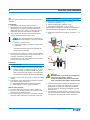
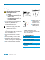
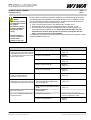
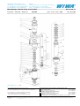
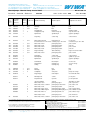
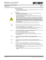
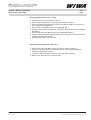
■ Place the gasket Pos. 18 onto the cylinder head Pos. 19.
Warning! The holes for both parts must be aligned properly.
■ Mount the control piston Pos. 27 to the control axle Pos. 28.
Warning! The long side with the groove must be facing upward.
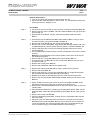
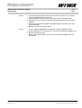
■ Screw a nut Pos. 26 onto the control axle Pos. 28 by using an open-end
wrench (SW 17).
Warning! A space of 2mm / .08 in. must remain between the control piston and
the nut.
■ Counter (lock) the nut with a second nut Pos. 26.
■ Lightly grease the control piston Pos. 27.
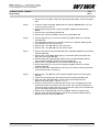
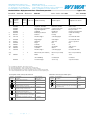
■ Slide four o-rings Pos. 29 onto the control cylinder Pos. 11.
■ Place the control cylinder into the control housing Pos. 12.
■ Place the control housing Pos. 12 over the control piston and onto the cylinder
head Pos. 19.
■ Using circlip pliers (A3), place a retaining ring Pos. 10 onto the groove in the
control cylinder Pos. 11.
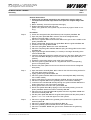
■ Place the cover Pos. 9 onto the control housing Pos. 12.
■ Screw the four threaded pieces Pos. 6 with one washer Pos. 7 each onto the
threaded bolts Pos. 8. Tighten them in a cross pattern with an open-end
wrench (SW 17).
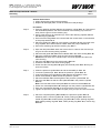
Step 1
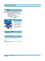
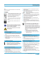
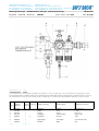
■ Place the muffler Pos. 4 and the perf. metal housing Pos. 5 onto the cylinder
head Pos. 19.
■ Place the cover Pos. 3 onto the muffler and perf. metal housing.
■ Screw the four dome nuts Pos. 1 to tighten down the cover in a cross pattern.
This requires an open-end wrench (SW 17).
Repair Manual
RA053+054+057+058+061+062+065+066•e•02.03
6
© Copyright 2002 WIWA Wilhelm Wagner GmbH & Co. KG