1
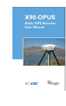
2 X90-OPUS GPS X900S-OPUS GNSS Static Receiver User Manual Revision K 2015.05.28 (B9317) 3 Copyright 2015 iGage Mapping Corporation All rights reserved. ‘iGage’ and ‘iGage Mapping Corporation’ are Trademarks of iGage Mapping Corporation of Salt Lake City Utah, USA. ‘CHC’ is a Trademark of Shanghai Huace Satellite Navigation Technology Limited of Shanghai, China All product and brand names mentioned in this publication are Trademarks of their respective holders. FCC Notice CHC X90-OPUS and X900S-OPUS GPS receivers comply with the limits for a Class B digital device, pursuant to the Part 15 of the FCC rules when it is used in the Portable Mode. Operation is subject to the following two conditions: (1) This device may not cause harmful interference and (2) this device must accept any interference received, including interference that may cause undesired operation. 4 Table of Contents Table of Contents ........................................................................... 5 Introduction ................................................................................... 7 The Really-Quick-Start Guide ........................................................ 8 In the Field ................................................................................. 8 Office / Desktop ......................................................................... 8 What’s in the X9x-OPUS Box ....................................................... 10 Technical Assistance .................................................................... 11 Warranty ...................................................................................... 11 Safety Information ....................................................................... 11 Warnings and Cautions ............................................................. 11 Use and Care .............................................................................. 12 Battery Safety and Disposal ...................................................... 12 Battery Warnings ....................................................................... 12 Batteries ....................................................................................... 13 Battery Charger ............................................................................ 14 Front Panel Operation ................................................................. 16 Pushbuttons ............................................................................... 16 On/Off Pushbutton .................................................................. 16 Record Pushbutton .................................................................. 16 LED Indicators ............................................................................ 17 Collecting Static Data ................................................................... 18 OPUS-Static, OPUS-RS and OPUS-Projects ............................. 18 Downloading, Processing and Archiving Data ............................ 21 Installing the Download Tool .................................................... 21 Downloading Data from X9x-OPUS GPS ................................... 21 Starting the X9x Download Tool ............................................... 23 Using the Download Tool ............................................................ 23 Submitting an Occupation to OPUS .......................................... 24 Setting the Receiver Type.......................................................... 27 Viewing the Observation Log .................................................... 27 Performing Quality Control Checks .......................................... 28 Advanced Download Settings...................................................... 28 Configuring the Download Tool .............................................. 28 'Base Project Folder' ................................................................ 30 'Archive All Projects' ................................................................ 30 'GPS Mounts on Drive' ............................................................. 31 ‘Minimum File Size to Transfer’ .............................................. 32 ‘Show UTC Time’ ...................................................................... 32 'Default HI' ............................................................................... 32 'Default Agency' ....................................................................... 33 'Default Operator' .................................................................... 33 'Decimate OPUS Submission to ...'.......................................... 33 'Your Email' .............................................................................. 34 'Show Advanced Settings' ....................................................... 34 ‘PPP Service’ ............................................................................. 35 Export 8.3 Filename ................................................................. 35 5 Format Extended .....................................................................36 Utilities........................................................................................36 “1. Undelete Occupations” .....................................................36 “2. HcRINEX Convertor” ..........................................................37 “3. Mark One File Unread” ......................................................37 “4. Mark All GPS Files Unread” ...............................................37 GPS Settings..................................................................................37 The ‘Log’ Tab ..............................................................................38 GPS 'Settings' Tab ......................................................................38 Recording Interval....................................................................40 Auto Sessioning ........................................................................41 Elevation Mask .........................................................................41 Update Firmware .....................................................................41 OPUS: What is it? .........................................................................44 OPUS-RS (Rapid Static) ..............................................................45 OPUS-Projects ............................................................................46 OPUS Error Messages and Failures .............................................46 Interpreting OPUS Results ...........................................................47 Getting ready to use OPUS ..........................................................48 Using OPUS-Projects ....................................................................51 Troubleshooting the X9x-OPUS Reciever....................................52 1. Receiver won’t turn on: .......................................................52 2. Is the receiver tracking satellites? ......................................52 3. Is the receiver storing observation data? ...........................52 4. The RED Power LED is flashing! ..........................................53 5. The GPS receiver won’t mount as a Disk Drive. .................53 6. Yellow and Green LED’s Flash Once Each Second .............53 X90-OPUS / X900S-OPUS 10-Pin Connector ...............................56 X90-OPUS / X900S-OPUS PC Data Cable .....................................57 X90-OPUS Antenna Calibration ...................................................58 X900S-OPUS Antenna Calibration ...............................................59 Converting a ‘Slant Height’ to ‘Vertical Height’: ......................60 Manually Converting Heights ..................................................60 Examples ..................................................................................60 Warranty.......................................................................................61 Exclusions .................................................................................61 RMA ..........................................................................................62 6 Introduction Thank you very much for choosing to purchase and use an X90-OPUS or X900S-OPUS receiver! These receivers can fill important niches in your surveying practice: Providing NGS CORS network based active control for your survey projects Providing the highest quality dual-frequency static data at price allowing multiple receivers With a ground-breaking price, outstanding performance and easy-to-use features, we know that your new static will be a valuable tool that quickly pays for itself. This guide is designed to help you familiarize yourself with your new equipment. If you have questions or suggestions, don’t hesitate to contact us: iGage Mapping Corporation 1545 South 1100 East Suite 1 Salt Lake City UT 84105 USA +1-801-412-0011 email [email protected] Your input is extremely valuable to us and we will listen to your suggestions! Software updates and news are available from: www.x90gps.com The Really-Quick-Start Guide In the Field 1. 2. Put a battery in the receiver. Mount the receiver over the point you want to survey. Level and measure the Instrument Height (HI.) For best results: align the button panel so it faces north, double-check your bubble and the instrument height (HI.) Record the HI, start time and point description in your field notes. Point Description HI Start Time End 1001 NW C Sec 14 2.0M V 9:45 am 1 March 2013 12:18 pm 3. 4. 5. Push the ON/OFF button and hold for 1-second until the lights flash. After 30 seconds the blue LED will flash once for every tracked Satellite. Verify that the yellow ‘Files’ LED flashes once every 5-seconds as the receiver logs data. Let the receiver record data for at least: OPUS-Rapid Static: OPUS-Static: 6. 16-minutes 121-minutes Turn the receiver off by pushing and holding the ON/OFF button for 1-second. Office / Desktop 7. 8. Install the download tool from the included DVD or from www.x90gps.com. Turn on the receiver, wait 10-seconds for the power LED to flash and then plug your X90 into a USB connector on your computer. 8 9. When/if you see the Windows AutoPlay screen: click on the red ‘X’ button on the upper-right corner. 10. Start the X9 Download tool from your desktop, push the ‘Download from GPS’ button: 11. Highlight the occupation, set the Point ID, the Description and the HI; push the ‘Submit to OPUS’ button. 12. When prompted press OK, then Control-V (to paste the file location and name,) then press the “Enter” key on your keyboard, or click on ‘Open’ to set the ZIP filename. 13. Finally press the ‘Upload to Rapid Static’ or ‘Upload to Static’ button as prompted at the bottom of the screen. 9 What’s in the X9x-OPUS Box Other than a suitable tripod or pole, X9 receivers are sold as complete kits, ready to record OPUS compatible static raw data sets. Each receiver kit includes these items: Carrying Case This User Manual One of these two heads X90-OPUS GPS Head X900S-OPUS Head GNSS Head GPS to PC Data Cable: Serial, USB and Ext. Power Two Lithium-Ion Batteries Dual Battery Charger Power Adapter with Cord: A Hold-A-Pole: External Battery Power Clips 10 Technical Assistance If you have questions or issues with your receiver, support is provided both by your dealer and iGage Mapping Corporation in Salt Lake City Utah: iGage Mapping Corporation 1545 South 1100 East STE 1 Salt Lake City UTAH 84105 +1-801-412-0011 For support questions by email: [email protected] Warranty Please see the full warranty at the end of this manual for details. The X9x-OPUS GPS receiver has a 2-year warranty. Cables and chargers are warranted for 1-year. Batteries are warranted for 90-days. Advanced replacement programs are available for mission critical applications. Service is provided by iGage Mapping Corporation in Salt Lake City Utah. Safety Information This manual describes the CHC X90-OPUS GPS and X900SOPUS GNSS Receivers. Before you use your receiver, please make sure that you have read and understood these warnings and safety requirements. Warnings and Cautions An absence of specific alerts does not mean that there are no safety risks involved. Warning and Caution information is 11 intended to minimize the risk of personal injury and/or damage to the equipment. Use and Care The X9x-OPUS receiver is a field ready instrument; however it is also a delicate electronic instrument. Take suitable care to avoid damage to the instrument. Avoid dropping the receiver as it can change the phase center of the antenna! Avoid storing the receiver at excessive temperatures (hot or cold) as it will damage the internal batteries. Avoid storing the batteries at temperatures less than -40° F (-40° C) and temperatures higher than 160°F (70°C) as it will permanently reduce the battery capacity and life DO NOT leave the X9x-OPUS or accessories inside a vehicle in the summer. Temperatures higher than 160°F will permanently reduce battery capacity and battery life. Battery Safety and Disposal The batteries are lithium-ion type cells. Battery Warnings WARNING - Do not damage the rechargeable Lithium-ion battery. A damaged battery can cause an explosion or fire, and can result in personal injury and property damage. To prevent injury or damage: Do not use or charge the battery if it appears to be discolored, warped, or leaking battery fluid. Do not expose the battery to fire, high temperature, or direct sunlight. Do not immerse the battery in water. Do not store the battery inside a vehicle during hot weather. Do not drop or puncture the battery. Do not open the battery or short-circuit its contacts. 12 Do not charge the batteries in chargers other than the supplied charger or a direct replacement. Do not charge similar batteries in the supplied charger, even if they fit well. WARNING - Avoid contact with the rechargeable Lithium-ion battery if it appears to be leaking. The battery fluid is extremely corrosive, and contact with it will result in personal injury and/or property damage. If battery fluid gets into your eyes, immediately rinse your eyes with clean water and seek medical attention. Do not rub your eyes! If battery fluid gets onto your skin or clothing, immediately use clean water to wash off the battery fluid. Batteries Two Lithium-Ion batteries are supplied with your receiver. Each battery, when new, will power the receiver: X90-OPUS GPS X900S-OPUS GNSS 6 hrs 15 minutes 9 hours at temperatures higher than 50 degrees F. At lower temperatures battery life is shortened. If you plan on running the receiver for longer than 4-hours, it is suggested that you use the supplied Battery Clip Cable to connect the auxiliary power connector to an external 12 volt battery. 13 Consider fully charging the batteries using the supplied charger before first use. Battery Charger Plug the charger into the supplied wall transformer or use the supplied alligator clip cable to connect to a 12 Volt battery. We supply alligator clips instead of cigarette adapters so you don’t have to leave your keys in the ignition if you need to field charge batteries. Two styles of chargers are supplied, which unfortunately have different LED blinking patterns. OLD STYLE CHARGERS The YELLOW LED lights when the left battery is inserted The RED LED lights when power is connected to the charger The Green LED lights when the right battery is inserted When no battery is inserted the LED is OFF -- -- -- -- -- When charging begins the LED blinks quickly --- -- As the batteries reach full charge, the LED blinks slower ---------------- When the LED’s stop blinking, the batteries are fully charged. 14 NEW STYLE CHARGERS The YELLOW LED represents the left battery -- The center RED LED lights when power is connected to the charger The GREEN LED represents the right battery -- -- When no battery is inserted the LED blinks ---------------- When charging begins the LED is on solid When the LED turns off, the batteries are fully charged. It is okay to leave charged batteries in the charger for extended periods of time. TOO COLD: Do not leave charged or uncharged batteries in your vehicle at night if the temperature will be less than 20 degrees F. Extreme cold battery storage will permanently reduce the capacity and lifetime of the batteries. TOO HOT: Do not leave charged or uncharged batteries in your vehicle on hot days with the windows rolled up when temperature will be higher than 90 degrees F. Hot temperatures will permanently reduce the capacity and lifetime of the batteries. 15 Front Panel Operation Pushbuttons The receiver’s front panel has two pushbuttons On/Off and Record: On/Off Pushbutton Press the On/Off button for 1-second and release to turn ON the receiver. Record Pushbutton The receivers are factory configured to automatically begin recording after the receiver is turned on. So really you don’t need to ever use the Record button. If the receiver is recording data, pressing the Record button for two seconds the receiver toggles from collecting data, to not collecting data and closes the current occupation file. The yellow Files LED will stop flashing when recording stops. When the receiver is not recording, pressing the record button again for two seconds will open a new observation file and begin collecting observation data (in a new file) again. 16 You can also use the Record button to check the collection state: Tapping the Record button will cause either the Serial or the Files button to flash: Serial green receiver is recording Files yellow receiver is NOT recording LED Indicators There are four LED indicators on the receiver: Power (Red) Power ON. If flashing, the battery charge is low. SV’s (Satellite Count) (Blue) Blinks once for each tracked satellite, waits 5seconds, repeats. Serial (Green) Blinks when data is received by the serial port. Blinks when the ‘Record’ button is pressed if the receiver is storing to a static file. Files (Yellow) Blinks each time data is stored to the static file. When the receiver turns on: All LEDs will flash The Blue SV’s LED will flash three times, then after 1second, once more After the Blue SV’s LED flashes three times, the receiver will automatically begin searching for satellites. When enough satellites are found to determine the receiver position and current date/time, a new occupation file is opened and the yellow Files LED will begin to flash, once each epoch (the default epoch is 5-seconds.) 17 NOTE: If the receiver is deployed after not being used for more than a month, or was last turned on more than a couple hundred miles from the current location, it may take an extra few minutes for the receiver to obtain a position. NOTE: if the yellow LED is not blinking, then the receiver is NOT collecting data. If you have waited a few minutes and the receiver is not collecting data, something is wrong. After the Blue SV’s LED flashes three-times, you may plug the receiver into your PC and it will mount as a fixed USB drive. To turn the X9x-OPUS off, press and hold the On/Off button for one second. All four LED’s will quickly flash three times and the receiver will power down. NOTE: If the two right LEDS (GREEN and YELLOW) flash at the same time, then the flash memory has been corrupted (typically by removing the cable while downloading data.) Check the troubleshooting section at the end of this manual for instructions on fixing this issue. Collecting Static Data OPUS-Static, OPUS-RS and OPUS-Projects Additional information on OPUS-Static and OPUS-Rapid Static can be found in the ‘OPUS’ section of this manual. Prior to using the receiver, charge the batteries to insure that the static occupation is not interrupted by power failure. A fresh battery when new and fully charged will run the receiver for X90-OPUS GPS X900S-OPUS GNSS 6 hrs 15 minutes 9 hours 18 When making occupations longer than 4-hours you should provide external power to the receiver with the included battery clips (or the power supply.) 1. Place a freshly charged battery into the receiver. 2. Place the receiver above the point you want to survey. 3. Rotate the receiver so the pushbutton panel faces the North. 4. Level the receiver. 5. Record the ‘Vertical Height’ from the top of the survey mark to the bottom of the receiver; alternatively you may measure a ‘Slant Height’ to the blue rubber gasket. 6. At a minimum, make a careful note of the following items in your field book: Start Time and Date Instrument Height (HI) PID (Point ID, Mark Name) Description Point Description HI Start Time 1001 NW C Sec 14 2.0M V 9:45 am 1 March 2013 7. 8. End Turn on the receiver. After 30 to 90-seconds, you will see the Yellow “Files” LED flash once every epoch (default 5-seconds) as the receiver records observables. Check that 5 or more satellites are tracked (the blue LED will blink 5 or more times.) Wait an appropriate time period for data collection: OPUS-RS (Rapid Static) Minimum of 15-minutes Maximum of 2-hours OPUS-STATIC 19 Minimum of 2-hours Maximum 48-hours 4-hours suggested minimum Remember that the data is going to be decimated to 15-second intervals. It is best to wait at least 1minute longer than required to insure that the decimation process does not leave your file too short. 9. At the end of the occupation Press and hold the ON/OFF key for one-second until the receiver closes the current file and turns off. 10. Make a note of the end time in your field book: Point Description HI Start Time End 1001 NW C Sec 14 2.0M V 9:45 am 1 March 2013 12:18 pm 20 Downloading, Processing and Archiving Data Your X9x-OPUS GPS receiver includes a download, preprocessing and archive tool called X9x Download for use with the NGS OPUS, RTX, AUSPOS and IBGE online products. Installing the Download Tool Insert the provided disk in the DVD ROM drive of your computer and the installation tool should automatically run. Follow the on-screen instructions to install the download tool and the X9x-OPUS support tools on your computer. You can always get the latest version of the X9x-OPUS Downloader from the internet and install it directly: http://www.x90gps.com Look for the ‘UPDATES’ button on the top of the page: Downloading Data from X9x-OPUS GPS Summary: Turn on the GPS, wait fo 10-seconds; plug in the USB Cable to your computer. 21 The X9x-OPUS receiver mounts just like a USB thumb drive (flash drive) on your Windows computer. No special drivers are required. To download data from your receiver: 1. 2. 3. 4. Turn on the GPS receiver Wait 10 seconds for the power LED (Red) to blink 3 times. Plug the USB connector into a port on your computer Wait for the Windows disk mount screen to appear When/if you see this ‘AutoPlay’ dialog, close it by clicking on the red ‘X’ in the upper-right corner. The first time you attach a receiver, you may need to wait up to 2-minutes for standard device drivers to be downloaded / installed. The drivers are built into Windows XP, Windows Vista, Windows 7 and Windows 8. The drivers are not distributed with the GPS receiver. If your X9x-OPUS receiver does not mount or an error message is displayed, you can usually unplug the receiver, wait a moment and plug it back in. If you continue to have problems check the ‘Troubleshooting…’ section at the end of this manual. 22 Starting the X9x Download Tool You can start the X9x download tool by clicking on the X9x Download shortcut on your desktop: Using the Download Tool Assuming the X9x-OPUS GPS receiver is plugged in and has mounted as a drive letter, just press the 'Download from X9x-OPUS' button: The program will automatically switch to the '_New' project and download every new file from your receiver. As the .HCN binary files are downloaded from the receiver they are automatically converted to RINEX and added to the '_New' project and finally displayed in the occupation grid. You can sort the grid by Filename, PID, Description, Operation, Agency, Start Date/Time, End Date/Time and Length by clicking on the column header. Clicking twice on the header will reverse order the grid. 23 You should select each occupation and either delete it: <- the ‘Delete Occupation’ button (if it is a short errant occupation) or enter the values you recorded in your field book: 1. 2. 3. 4. 5. PID (Point ID) A unique short identifier for each marker (usually a 4 digit integer.) Only letters, numbers and the underscore are allowed in the PID. Description A longer description of the point. Note that quotes “ and ‘ are not allowed in the description. HI The Instrument Height which is the distance from the ground mark to the bottom of the receiver add ‘F’ to enter feet add ‘S’ to enter slant height add ‘SF’ or ‘FS’ to enter slant feet height Operator This value gets placed in exported RINEX files Agency This value gets placed in exported RINEX files If the ‘_New’ folder gets too full, you can make a new project folder (with the “+” button) and move occupations to the project: Submitting an Occupation to OPUS Once all of the new occupations have been deleted or assigned to a project you can submit an occupation to NGS OPUS, NGS OPUS-RS, RTX, AUSPOS. IBGE or post-process them using other software / services. Click on an occupation to select it: 24 Click on the 'Submit for OPUS' button: U.S. National Geodetic Survey Note, you may select an alternative PPP Service provider (on the configuration tab.) Some of the alternative providers are: Trimble’s RTX Service AUSPOS Brazilian Institute of Geography and Statistics The currently selected occupation will be processed and prepared for upload to OPUS: 1. 2. 3. 4. the file is decimated to 15-second epochs, header information is stuffed the file is run through TEQC to insure it will be acceptable to OPUS an Observation file and a Navigation file are generated the Observation file is compressed into a ZIP file If the ‘Show Advanced Settings’ is set to “Simple” then the program will skip directly to the ‘Verify Filename to Upload’ screen (shown below.) If ‘Show Advanced Settings’ is set to “Normal”, “Support OPUS-Projects” or “Advanced” then this ‘RINEX Solution’ helper screen is shown: 25 The program will suggest which service (OPUS-Static or OPUS-RS) and list the time since the end of the occupation. You can click the 'Submit to OPUS' button: to automatically open an internet browser at the NGS OPUS Submission form. When the web page has loaded, the program will automatically fill in the ‘Antenna Type’, the ‘Antenna Height’ and the ‘Email address.’ Verify Filename to Upload: The program will prompt you: Click OK and then ‘Choose File to Upload’ will be displayed: Press Control-V, then the ‘Enter’ key on your keyboard. You may also press Control-V, then click the ‘Close’ button with your mouse. The NGS OPUS Submission form will be ready to submit, check the entries and any extended options that you might 26 want to use. The status bar will prompt you with the correct submission button: Press either the ‘Upload to Rapid-Static’ or ‘Upload to Static’ button as directed and your occupation will be uploaded to OPUS for processing. Setting the Receiver Type (Hidden when Simple) When files are downloaded from the receiver, the receiver type is associated with the .HCN file. The ‘Receiver Model’ shows an occupation’s associated hardware type: If this is consistently incorrect, you can modify the device type while it is connected on the ‘Configuration’ tab. Viewing the Observation Log (Hidden when Simple) A detailed log is automatically kept for the files that you download and submit for processing. Pressing the ‘Log’ button shows the log file for the currently selected observation: 27 Pressing the ‘Append’ button adds a date/time stamp and opens the log for user editing. Press ‘Save’ to store your changes or ‘Close’ to close without saving. Performing Quality Control Checks (Hidden when Simple) Pressing the button will launch the UNAVCO TEQC tool and run a standard RINEX QC run on the currently selected observation file. When the run is complete, the results will be shown in a window: You can press the ‘TEQC Help’ button to download the User Guide for TEQC from the UNAVCO web site. TEQC is a great tool for evaluating both the receiver’s performance and the site suitability for collected data. We use it to verify receiver operation in our hardware validation process. Advanced Download Settings Configuring the Download Tool Click on the 'Configuration': 28 At a minimum enter these values: Agency your company name Operator the name of the default operator Email your email address If you change ‘Show Advanced Settings’ from ‘Simple’ to ‘Normal’, ‘Support OPUS Projects’ or ‘Advanced’ additional setup values are shown: 29 You can change the rest of the configuration values as needed. Here are detailed descriptions for each of them: 'Base Project Folder' (Hidden when Simple) This is the full Window’s path to the base folder where all of the data is stored. The default location is in your 'Documents' folder in a folder named 'X90-OPUS'. Double-click over the current path to change the folder location. The download tool will create a sub-folder for each Project that you add. In addition there are always three special folders: _New _Deleted _Error new occupation files downloaded from the receiver are placed here first if you delete an occupation, it is not really deleted, just moved to the _Deleted folder. An undelete function is included in Utilities. sometimes short occupations won't include navigation records, these short files end up here. 'Archive All Projects' (Hidden when Simple) Pressing the 'Archive' button to the right of the Base Project Folder entry will backup every occupation in every project to a single ZIP file. This is handy if you want to move all of your data to another computer or make regular disaster backups. There are similar Archive buttons on the main page: one archives the current occupation and the other archives the current project. 30 The download tool does not provide a method to restore these backups, however they are standard ZIP files and the Windows operating system does include a tool to decompress them. 'GPS Mounts on Drive' This is the drive letter that the GPS receiver was last found on. Don't worry if the drive letter changes, the program will automatically find the receiver when you download data. If you want to verify that the GPS receiver is connected and has successfully mounted as a drive, press 'Find GPS'. Note: If you manually delete every single file and folder from the GPS receiver, the program won't be able to automatically find the receiver until after the GPS has recorded at least one file. ‘Update GPS Model’ (Shown only when Advanced selected.) The GPS Model is written into the receiver at the factory. If you delete ALL of the files on the receiver or format the receiver (it is a standard flash drive) it is possible that it will lose its receiver type. With the receiver attached to your computer with the USB cable, click on the ‘Update GPS Model’ button to display this dialog: 31 Use the drop down ‘Receiver Model’ to change the receiver type. If the HCN Key has been lost, it is written on a white sticker inside the battery compartment. You cannot edit the ‘Receiver Serial Number’. If the HCN Key has been correctly entered, the ‘OK’ will be shown in a green box, otherwise it will display ‘????’ in a red box. The correct HCN key will be printed on a white label inside the battery compartment. ‘Minimum File Size to Transfer’ (Hidden when Simple) Every time you turn on the GPS receiver, it will attempt to track satellites and open a new occupation file. Often several small junk files will be created that don't have any meaningful data and are of no value. The download tool will automatically ignore files smaller than this minimum value. This keeps useless files from cluttering your computer. ‘Show UTC Time’ When unchecked (the default,) the download tool will show the observation start and end times in your local time zone. If you check 'Show UTC Time', then the times are displayed in UTC time. 'Default HI' When you download an occupation from the receiver, this HI will be the default associated with every occupation. You can change the HI for each individual occupation later, this is just the default. 32 If you ALWAYS use a 2-meter range pole, then this value will always be 2.000 and you won't have to worry about HI blunders. FEET: If you measure up in feet, you can enter the height in decimal feet and put an 'F' after the measurement. The program will automatically convert to Meters for you. SLANT HEIGHT in Meters: If you measure a slant height, enter an ‘S’ after the measurement and the program will compute the vertical height for you. SLANT HEIGHT in FEET: If you measure a slant height in feet, enter ‘SF’ or ‘FS’ after the measurement and the program will compute the vertical height in Meters for you. Note: if you use the ‘PPP Service’ = ‘RTX (CenterPoint)’ the submitted RINEX file spoofs a ‘UNKNOWN EXT NONE’ and adjusts your actual HI to reflect the generic antenna L1 offset. 'Default Agency' Enter your company name here. This value is placed into every RINEX file that is exported. You can override this value on a file-by-file basis. 'Default Operator' Enter the default name of the operator here. This value is placed into every RINEX file that is exported. You can override this value on a file-by-file basis. 'Decimate OPUS Submission to ...' (Hidden when Simple) When you submit a file to OPUS, it is always decimated at the NGS server to 15-second epochs (recording interval = 1 33 point every 15 seconds.) The default recording interval for the X9x-OPUS is 5-seconds. By pre-decimating the RINEX file before upload, it is reduced to 1/6th the size. This makes the upload process much faster while having no impact on the resulting solution. Observations submitted to RTX are not decimated, AUSPOS submissions are decimated to 15 seconds. Observations exported directly to RINEX are not decimated. 'Your Email' When you submit a file to OPUS, you need to provide your Email address so the OPUS processor can return a solution to you. The email address that you enter here will be used for all automatic submissions.. 'Show Advanced Settings' This setting determines the complexity of the X9x-Download program. Simple: (the Default setting) Hides archive functions, Minimum File size, Receiver Model, Antenna Name Decimate setting, QC function, Export to RINEX button, OPUSProjects, the GPS Settings tab and the Log tab. Normal: Shows everything except for OPUS-Projects, the GPS Settings and Log tab. OPUS-Projects: Displays the OPUS-Projects checkbox which allows automatic submission to a NGS registered project. Advanced: Displays the GPS Settings and Log tabs. 34 Typically you will never need to use the 'Advanced' functions. ‘PPP Service’ (Hidden when Simple) The X9x-Download tool supports several PPP (Precise Point Positioning) services. The submit button on the main page tracks this setting and the upload strategy is adjusted to each available service. Additional Information is available on each service on the web: OPUS: http://geodesy.noaa.gov/OPUS/ RTX: http://trimblertx.com AUSPOS: http://www.ga.gov.au/bin/gps.pl IBGE: http://www.ibge.gov.br/home/geociencias/geodesia/ppp/default.shtm Export 8.3 Filename (Hidden when Simple) Normally, the X9 Download program submits files using filenames like this: 917226_14_072_A0.OBS The device serial number, the year, the Julian day of year and the observation number. Some services and programs prefer names in an 8.3 (xxxxxxxx.xxx) format. Checking this box results in exported filenames like: 10050720.14O 35 Where 1005 is the Point ID, 072 is the Julian date, 0 is the observation number, 14 is the year and O indicates an observation file. Format Extended (Only shown when PPP Service = OPUS) The NGS returns three styles of reports: Standard: Single Page Report Extended: Standard + baseline details + State Plane in (s)Ft Standard + XML: Single Page + XML For new OPUS users, the ‘Format Extended’ includes one important addition: State Plane coordinates are shown in both Meters and US Survey Feet (or International Feet) at the bottom of the report. We keep ‘Extended’ checked by default for this reason. Prior to submitting an OPUS report, you can modify any of the Option settings, however checking this box results in the extended output always being checked. Utilities (Hidden when Simple) Additional utilities for working with observations are included. “1. Undelete Occupations” When you delete an observation, it is actually moved to a special “_Deleted” folder. Clicking the Undelete Occupation button allows you to specify a deleted observation to restore. When an 36 occupation is undeleted, it is always returned to the _New project. “2. HcRINEX Convertor” Files are stored on the receiver in a .HCN binary file. When the ‘X9 Download’ tool downloads a file, it is automatically converted to standard RINEX using the HxRINEX tool. Clicking this button runs the HcRINEX tool in manual mode. You can browse for HCN files and manually convert them to standard RINEX files. Results are always placed in a subfolder named ‘RINEX’ under the file to be converted. “3. Mark One File Unread” When files are downloaded from the receiver, they are not deleted from the receiver. The filename on the receiver is modified to begin with an underscore ‘_’. This function allows you to specify a single file to mark as ‘unread.’ Once a file is unread the next download action will re-download and convert the file. “4. Mark All GPS Files Unread” This function marks EVERY observation file on the receiver as unread. The next download will read every single file on the receiver. (This will take quite a bit of time if your receiver had hundreds of files.) GPS Settings (Hidden when Simple) To modify the ‘GPS Settings’ or view the log, select the 'Configuration' tab, then choose 'Show Advanced Settings = Advanced.’ 37 When ‘Advanced’ is selected, two additional tabs will be displayed: The ‘Log’ Tab The ‘Log’ tab shows detailed results of the current program operation. It may be useful to debug some aspect of file processing. GPS 'Settings' Tab The 'GPS Settings' tab allows you to change these receiver behaviors: Automatic End of Sessioning Recording Interval for Static Data Elevation Mask Check and Update Receiver Firmware 38 To configure the GPS settings, first connect the GPS receiver to your computer using the 'Serial Port' connector. If your computer does not have a built-in serial port, you will need to use a 'USB to Serial' converter. (Follow the installation instructions for your 'USB to Serial' converter.) Turn on the GPS receiver, check the 'Show Advanced Settings' checkbox and select the 'GPS Settings' tab: The configuration tool should automatically detect the correct COM (Serial) port number. If you have more than one serial port, you may need to manually adjust the 'COM Port' setting to match the port that the GPS is connected to. If you plug a USB-to-serial port adapter into your computer after starting the download tool, press the refresh button: the program should find the newly installed port. (Only ports in the range 1 through 32 are detected.) 39 Click on the 'Read GPS' button: The configuration tool will interrogate the GPS receiver and display the 'Receiver Type', the 'Receiver ID' (the Serial Number), the GPS 'Firmware Revision' and the 'Device PN'. The current values for 'Auto Sessioning', 'Recording Interval' and 'Elevation Mask' will also be shown and can be edited. To return to the factory defaults: 'Auto Sessioning' 'Recording Interval' 'Elevation Mask' None 5-seconds 0 degrees Press the 'Set Defaults' button: Or you can change the settings as required for your application. When you have made your selections, click on the ‘Update GPS’ button to send the changes to the GPS receiver. Additional details for each of these settings follow. Recording Interval The recording interval defaults to 5-seconds on the X9xOPUS. Additional recording rates are also available: 1 second, 2 seconds, 3 seconds...59 seconds 1 minute, 2 minutes, 3 minutes…190 minutes 2 Hz , 5 Hz The default interval (5-seconds) allows for files to safely contain over 7-days of continuous observations. Files containing more than 250,000 points may be unusable by the conversion tools and should be avoided. The X9x-OPUS is not a suitable receiver for applications that required huge data sets (more than 500,000 observations per file.) If you intend to use the observation files with OPUS you must use one of these recording intervals: 40 1, 2, 3, 5, 10, 15 or 30 seconds Auto Sessioning The default 'Auto Sessioning' setting is 'NONE.’ Some applications may benefit from having the receiver automatically close files after a preset period. ‘Auto Sessioning’ only closes the current file. A new file is not automatically opened. Elevation Mask The default setting for ‘Elevation Mask’ is 0 degrees. All visible satellites are tracked. OPUS automatically ignores satellites lower than 10degrees. There is a benefit to having the receiver track satellites for as long as possible as they rise to 10-degrees. (We don’t want to start tracking at the exact moment that OPUS begins to use the satellite.) The X9x-OPUS receiver has a large ground plane antenna which has been optimized for tracking low elevation satellites. The internal memory of the receiver is huge. There probably is no advantage to raising the tracking elevation for any application and it is recommended that you keep the tracking angle set to the default 0-value unless you have a really good reason do change it. Update Firmware Updating the firmware in your receiver requires that the GPS be connected to a COM port on your computer (COM1 is best) and that your computer has an active internet connection. To update your receiver firmware click on: 41 Once the current receiver’s firmware version is shown: the ‘Check Web for Newer’ will be enabled. Click on: The program will check the internet for a newer version of GPS control software: If updated firmware is available, the new firmware will be downloaded and the ‘Update Firmware’ button will be enabled, click on: The program will request that you turn off the receiver: The firmware will be downloaded and a short instruction screen is shown: 42 Click on OK. The firmware uploader tool will be displayed: Click on the ‘Update’ button: Turn on the GPS receiver: After 5-seconds, the blue-bar will slowly move across the uploader screen. When it reaches the end: Click on OK, then wait 30-seconds, turn off the GPS receiver, finally turn it back on. Your receiver has the latest firmware. 43 OPUS: What is it? OPUS (Online Positioning User Service) is a free service provided by the NGS (National Geodetic Survey.) From the NGS Website: “This Online Positioning User Service (OPUS) provides simplified access to high-accuracy National Spatial Reference System (NSRS) coordinates. Upload a GPS data file collected with a survey-grade receiver and obtain an NSRS position via email. OPUS requires minimal user input and uses software which computes coordinates for NGS' Continuously Operating Reference Station (CORS) network. The resulting positions are accurate and consistent with other National Spatial Reference System users.” Here are direct links to more detailed information: http://geodesy.noaa.gov/INFO/OnePagers/OPUSOnePager.pdf http://geodesy.noaa.gov/OPUS/about.jsp One of the most important contributors to vertical accuracy computed by OPUS-Static is the length of occupation. Longer times are better. If you are concerned about elevation, please remember that a 2 hour OPUS static observation has an expected height accuracy of 2.5 cm. A 6-hour occupation has an expected accuracy of 1.5 cm. Again, longer times are better. Your expectations should be tempered by this NGS graph: 44 OPUS-RS (Rapid Static) Standard OPUS-Static sessions require 2-hour observations. OPUS-RS sessions can be as short as 15-minutes. However, OPUS-RS solutions are not available universally. In general, OPUS-RS requires: 3 (or more) CORS within 250 km of your site your site must be within 50 km of the polygon formed by the CORS sites If you are working in Southwest Nevada, along the highline of Montana or in North or South Dakota, OPUS-RS probably will not work and you will have to collect more than 2 hours of data for submission to OPUS-STATIC! Prior to collecting data for OPUS-RS check the latest status map to insure that OPUS-RS will work. The online OPUS-RS resource http://geodesy.noaa.gov/OPUSI/Plots/Gmap/OPUSRS_sigmap.shtml is updated routinely and reflects the probability that an occupation at a given location will be successful and the expected accuracy for a 15-minute and 1-hour occupation. In some areas there is a risk that if a single CORS site is unavailable, your OPUS-RS job will not be processed. Caution and planning are suggested for OPUS-RS jobs. 45 OPUS-Projects OPUS Projects is a relatively new online tool. Its use requires taking a NGS training class, but the invested time is well worth it as OPUS-Projects will allow you to combine the observation files from multiple receivers and multiple sessions. There is an excellent article and video describing OPUS Projects in the October 2013 ‘American Surveyor’ magazine. Search for “OPUS-Projects: The Next Revolution in GPS” to find a full resolution PDF. OPUS Error Messages and Failures There are lots of possible error messages when processing OPUS solutions. It is our experience that almost all errors fall into a single category: “There is not enough nearby CORS data to effectively process your occupation…yet.” In general, the solution is nearly always the same: “Wait until more data becomes available and resubmit your job.” If you are processing OPUS-RS jobs in an area with very few CORS stations, and one CORS station was offline, waiting will not help. OPUS-Static is the solution for locations where OPUS-RS is not dependable. CORS stations can report observations hourly or daily. In some areas (typically UNAVCO PBO sites) most of the sites report once at the end of each day (GMT.) So data that is needed to process your job is not available until 4:00 am GMT on the day after you collect data. The X9 Download tool allows you to submit jobs to alternative services like AUSPOS and RTX. Typically these alternative services closely match OPUS. 46 If you submit an observation to OPUS and nothing comes back, check your SPAM folder. OPUS solutions are regularly misidentified as spam. OPUS is sometimes unavailable or takes longer than other times. Interpreting OPUS Results When you receive an OPUS solution by email from the NGS, it will look something like this: USER: [email protected] RINEX FILE: p4490900.14o SOFTWARE: EPHEMERIS: NAV FILE: ANT NAME: ARP HEIGHT: DATE: May 06, 2014 TIME: 16:08:35 UTC page5 1209.04 master93.pl 022814 START: igs17861.eph [precise] STOP: brdc0900.14n OBS USED: TRM29659.00 SCIT # FIXED AMB: 0.0083 OVERALL RMS: REF FRAME: NAD_83(2011)(EPOCH:2010.0000) E W EL ORTHO X: Y: Z: -2184137.494(m) -3839941.381(m) 4585410.516(m) LAT: LON: LON: HGT: HGT: 46 15 35.23578 240 22 8.47069 119 37 51.52931 208.861(m) 230.163(m) Northing (Y) [meters] Easting (X) [meters] Convergence [degrees] Point Scale Combined Factor 0.003(m) 0.001(m) 0.005(m) 2014/03/31 00:00:00 2014/03/31 23:59:00 45735 / 47174 :97% 162 / 171 :95% 0.011(m) IGS08(EPOCH:2014.2452) -2184138.362(m) 0.003(m) -3839940.177(m) 0.001(m) 4585410.529(m) 0.005(m) 0.005(m) 46 15 35.25052 0.005(m) 0.002(m) 240 22 8.40767 0.002(m) 0.002(m) 119 37 51.59233 0.002(m) 0.003(m) 208.444(m) 0.003(m) 0.018(m) [NAVD88 (Computed using GEOID12A)] UTM COORDINATES UTM (Zone 11) 5126276.950 297235.684 -1.90148112 1.00010542 1.00007268 STATE PLANE COORDINATES SPC (4602 WA S) 103343.987 566995.383 0.63125220 0.99993063 0.99989789 Here are some general rules to help judge the quality of a solution: The orbit [precise] should be precise or rapid (not-ultra rapid.) > 90% observations used or > 80% # Fixed Ambiguities > 50% Fixed Ambiguities or > 95% observations used Overall RMS < 0.030(m) Lat / Lon RMS < 0.030(m) If you collect data under canopy or in an area where there are buildings or trees that obstruct the view above 10° elevation, the number of observations used will be lower. 47 Make sure you use the left-hand column (NAD_83) results, not the right-hand column (IGS08.) Be careful with heights. Both ellipsoid and orthometric heights are listed. The orthometric height is NAVD88 GPS derived and typically is the elevation you need. The RMS error estimate for the orthometric height includes an error estimate for the GEOID in addition to the RMS value for the ellipsoid height. The state plane coordinates are listed at the bottom in the right-hand column. They are in Meters. If you need Feet, you can convert them, however be careful to convert to International Feet or U.S. Survey Feet as required by your State and application: US Survey Feet International Feet = Meters * (3937/1200) = Meters / 0.3048 The misapplication of Ft/M scale factor can result in a 30 foot coordinate blunder! If you request an ‘Extended Format’ OPUS results, the state plane coordinates are computed and returned at the bottom of the report. If your survey is at a significant elevation (> 100 feet) you may need to apply the Combined Factor (listed on the OPUS report for both UTM and State Plane Coordinates) to inversed distances to match optical shots made at ground level. Getting ready to use OPUS OPUS is a great tool for grounding your survey. But OPUS is part of a larger toolset. Before you begin a project take a moment to think about the ‘Big Picture’: A. What are your GOALS? a. Required accuracy b. Horizontal and Vertical Datum; Geoid model choice 48 c. d. Survey style: OPUS-Static, OPUS-Rapid Static, OPUS-Projects Consider FGDC Standards: http://www.fgdc.gov/standards/projects/FGDC-standards-projects/accuracy B. C. D. Are there passive marks available for control? a. Will CORS, passive or a combination control the survey? b. Are local passive marks recoverable, undisturbed, sufficient quality, stable and GPS friendly? c. Where are the nearby NGS CORS (active) marks? This will determine ‘Rapid Static’ or ‘Static’ availability. OPUS-Rapid Static Requirements a. Find the closest 9 CORS sites with available observations b. A minimum of 3 CORS stations within 250 KM are required. c. Your site must be within 50 km of a polygon created by the remaining available CORS. d. If the eligible CORS count is low, check the past reliability of recent observations to insure that there is a high probability of sufficient sites for OPUS-RS to compute a solution. Use the CORS ‘Data Availability’ to check for recent observations: Mission Planning: Satellite Availability and Network Planning 49 a. E. F. G. How many receivers will you use for simultaneous observations? If you are using OPUS-Projects then More = More-Better. b. Checkout online ‘Mission Planning’ tools for U.S. satellite availability using reasonable masks (>15 degrees) during collection periods. If there are any periods with fewer than 6 SV’s or PDOPS higher than 3, plan on occupying points longer. How long will you observe a site? Again: Are your sites GPS compatible? Are there obstructions higher than 10 degrees? Field Checklist: o Maps, aerial photography, ingress/egress plans o Receiver with memory available o Batteries fully charged plus battery-to-receiver cables with 12V external battery o Compass for orienting receiver to North, current declination o Fixed Height Tripods: Bubbles calibrated? Height verified? o Tripods / Bipods /Tribrachs / Tribrach adaptors: Tribrachs calibrated? o Tools for adjusting bubbles (the correct Allen wrenches) o Measure tape for slant measurements o Digital Camera, batteries, memory: take close ups of cap and 4 horizon shots w/ receiver o Station information observation log sheets o Inclinometer for checking and documenting horizon obstructions o Field Book, Observation Schedule, pencils o Cell phone o Flagging, paint, PK nails, hubs, rebar, caps, hammer o Fluorescent vest, hat, bug dope, sunscreen, lunch, water, traffic control equipment 50 o Names, addresses, telephone numbers of property owners o Gate keys / combinations Using OPUS-Projects If you are contributing occupations to a registered OPUSProject (note that NGS Training and authorization is required to use ‘OPUS-Projects’), the X9x-Download tool can assist you when uploading files: 1. Turn ON OPUS-Projects support. On the ‘Configuration’ tab, set ‘Show Advanced Settings’ to “Support OPUSProjects”: 2. Add the NGS registered OPUS-Projects ‘Project Identifier’ supplied by your project administrator: Click the “+” button Enter the exact identifier as the new project name. Select the new Project and check the newly displayed ‘OPUS-Project’ checkbox. 51 3. Now, when you submit an occupation that has been moved to the project, the upload tool will automatically press the ‘OPTIONS’ button on the OPUS submission form and fill in the project identifier: Troubleshooting the X9x-OPUS Reciever 1. Receiver won’t turn on: Battery is installed backwards or upside down! Remove and install properly. Battery is fully discharged: Charge battery or use external power. Contacts on battery are dirty: Clean battery and receiver contacts with a soft cloth. Battery is bad: Try another battery. 2. Is the receiver tracking satellites? The BLUE LED flashes once for each SV (satellite vehicle) that is currently tracked. If you are indoors, the LED will flash once every 5-seconds. However no SV’s will be tracked. The receiver should begin tracking within 30-seconds after a warm start. After a cold start (off for more than 1 week) it may take 90-seconds for the receiver to begin tracking. 3. Is the receiver storing observation data? The right-hand YELLOW LED will flash once every time data is stored to the current occupation file. The default recording rate is 5-seconds, thus the YELLOW LED will flash once every 5-seconds when data is being stored. 52 It is possible to stop the recording of data and close the observation file by pressing and holding the BLUE Record button. You can verify the mode by quickly pressing the record button: If the GREEN radio LED flashes, then the receiver is RECORDING. If the YELLOW files LED flashes, then the receiver is NOT RECORDING. 4. The RED Power LED is flashing! If the RED Power LED is flashing, then the internal battery is low. Connect external power or turn receiver off and replace battery. 5. The GPS receiver won’t mount as a Disk Drive. A. Before plugging GPS cable into your PC try turning on the GPS and waiting for 20 seconds? B. Unplug, wait 15-seconds, try again C. Try another USB port. D. Use an external USB Hub (this fixes intermittent disk mounts, but we don’t know why.) E. Try other computers. F. Try turning off your PC, wait a minute and then turn on again. Reinsert the USB cable. G. Get the DevView tool from http://www.nirsoft.net/utils/usb_devices_view.html and use it to uninstall the errant device driver for the GPS receiver. Download the USBDeview tool, there is a 32-bit and a 64-bit version, choose the correct version for your computer. Unzip the distribution ZIP file, run the “USBDeview” tool as an administrator. Unplug the GPS receiver. Look for the entry “OLIMEX LPC1766 Storage USB Device”, right-click it and “Uninstall Selected Devices”, answer yes to ‘Do you want to uninstall?” wait 10-seconds and then plug the GPS receiver back in. 6. Yellow and Green LED’s Flash Once Each Second If your receiver has both the YELLOW and GREEN LED’s flash simultaneously: 53 BLINK SIMULTANEOUSLY OR UNEXPECTEDLY Then the internal flash memory directory block has become corrupted. This is a status message indicating that the receiver is unable to open or write to a new file in the 4 GB Flash memory. Follow these instructions to fix this issue: Attach the receiver to a computer, it will mount as a disk drive letter. Note the drive letter. If your operating system requests that you check the disk for errors, do so. Download all of the current files from the receiver using the X9x-Download tool. Reformat the X9x-OPUS receiver using the Windows Explorer on your computer. More Information The receiver is a flash memory drive. Just like a real thumb drive, the directory block on the flash memory can become corrupted if the battery dies at the exact moment the receiver is writing to the occupation file (once every 5 seconds typically) or if the USB cable is removed from a computer while the receiver is downloading a file, or if the battery dies while the receiver is attached to a computer. Just as a USB thumb drive can become corrupted, the receiver’s memory will suffer the same issue. Sometimes a ‘Checkdisk’ operation will fix this issue, however a drive format will always fix this issue. The chance of the battery expiring at the exact same moment that the receiver is writing occupation to the flash memory is extremely low: the write occurs once every 5seconds (by default) and the write operation is very-very quick. In addition, the receiver monitors the battery voltage and automatically closes output files and shuts 54 down a few seconds before the battery expires. However, if the battery has been allowed to deplete and then is used when downloading to the computer the battery will likely run down while the files are transferring. Downloading files keeps files open most of the time and the probability of a nearly depleted battery failing during transfer is quite high. For this reason, it is best to use a freshly charged battery when downloading a receiver to a PC. 55 X90-OPUS / X900S-OPUS 10-Pin Connector WARNING! If you attach external power with reversed polarity you will destroy the GPS receiver. PIN Signal Name Description 1 TXD Transmit Data(PC receive data through this pin) 2 RXD Receive Data(PC transmit data through this pin) 3 PWR External Power Input (9-15 V DC) 4 PWR External Power Input (9-15 V DC) 5 GND External Power Ground 6 GND External Power Ground 7 USB PWR 8 D- 9 D+ 10 Not Used 56 X90-OPUS / X900S-OPUS PC Data Cable The supplied interface cable includes connections for GPS, USB, Serial and External Power: Interface Cable External Power Battery Clips External power should be in the range: 9 VDC to 18 VDC. The supplied battery clip cable includes a fuse and is reverse polarity protected. 57 X90-OPUS Antenna Calibration The NGS (National Geodetic Survey) Absolute calibration for the X90-OPUS is: “CHCX90D-OPUS NONE”: L1 Offset: 089.3 mm L2 Offset: 101.7 mm Radius to edge of knob on case: 0.117 M (0.386 Ft); Slant Measurement Point (bottom of blue gasket) height above ARP: 0.047 M (0.155 Ft) 58 X900S-OPUS Antenna Calibration The NGS (National Geodetic Survey) Absolute calibration for the X900S-OPUS is: “CHCX900S-OPUS NONE”: L1 Offset: 81.35 mm L2 Offset: 97.55 mm Radius to edge of knob on case: 0.10195 M (0.334 Ft); Slant Measurement Point (bottom of blue gasket) height above ARP: 0.04000 M (0.132 Ft) 59 Converting a ‘Slant Height’ to ‘Vertical Height’: The X9 Download tool automatically converts from ‘feet to meters’ and from ‘slant to vertical’ using the currently selected receiver model. If you have a vertical measurement in feet you can enter an ‘F’ after the measured vertical height: “4.512 F” becomes “1.375” meters vertical If you have a slant height in feet you can enter a ‘FS’ (or ‘SF’) after the measured slant height: “4.512 FS” becomes “1.323” meters vertical If you have a slant height in meters, enter an ‘S’ after the measured slant height: “1.523 S” becomes “1.472” meters vertical Manually Converting Heights Receiver X90S-OPUS X900S-OPUS r (meters) 0.117 0.102 h (meters) 0.047 0.040 𝑣 = √s2 − r 2 − h Examples Measured Slant s (feet) 6.965 5.148 X90-OPUS Vertical v (meters) 2.073 1.518 Slant s (m) 2.123 1.569 60 X900-OPUS Vertical v (meters) 2.081 1.526 Warranty IMC is “iGage Mapping Corporation” of Salt Lake City Utah USA. IMC warrants the X9x-OPUS receiver to be free of defects in material and workmanship and will conform to our published specifications for these periods: GPS receivers: Cables and accessories: Batteries: 2-years 1-year 90-days This warranty applies only to the original purchaser of the product. Hardware: Purchaser's exclusive remedy under this warranty shall be limited to the repair or replacement, at IMC's option, of any defective part of the receiver or accessories which are covered by this warranty. Repairs under this warranty shall only be made by IMC at an IMC service center. Any repairs by a service center not authorized by IMC will void this warranty. In the event of a defect, IMC will at its option, repair or replace the hardware product with no charge to the purchaser for parts or labor. The repaired or replaced product will be warranted for 30-days from the date of return shipment, or for the balance of the original warranty, whichever is longer. Software: IMC warrants that software products included with hardware products will be free from media defects for a period of 30-days from the date of shipment and will substantially conform to the then-current user documentation provided with the software. IMC's sole obligation shall be the correction or replacement of the media so that it will substantially conform to the then-current user documentation. IMC does not warrant the software will meet purchaser's requirements or that its operation will be uninterrupted, error-free or virus-free. Purchaser assumes the entire risk of using the software. Exclusions The following are excluded from the warranty coverage: 1. 2. 3. 4. 5. 6. Periodic maintenance and repair or replacement of parts due to normal wear and tear. Product Finishes. Batteries exposed to heat, cold; or batteries opened or physically damaged. Installations or defects resulting from installation. Any damage caused by (i) shipping, misuse, abuse, negligence, tampering, or improper use; (ii) disasters such as fire, flood, wind, and lightning; (iii) unauthorized attachments or modification. Service performed or attempted by anyone other than an authorized IMC service center. 61 7. 8. That the receiver will be free from any claim for infringement of any patent, trademark, copyright or other proprietary right, including trade secrets. Any damage due to accident, resulting from inaccurate satellite transmissions. Inaccurate transmissions can occur due to changes in the position, health or geometry of a satellite or modifications to the receiver that may be required due to any change in the GPS. IMC GPS receivers use GPS satellites to obtain position, velocity and time information. GPS is operated by the US government, which is solely responsible for the accuracy and maintenance of the GPS system. OPUS and OPUS-RS is a service of the NGS and IMC shall not be responsible for issues with NGS provided services. Except as set forth in this limited warranty, all other expressed or implied fitness for any particular purpose, merchantability or non-infringement, are hereby disclaimed. IMC shall not be liable to the purchaser or any other person for any incidental or consequential damages whatsoever, including but not limited to lost profits, damages resulting from delay or loss of use, loss of or damages arising out of breach of this warranty or any implied warranty even though caused by negligence or other fault of IMC or negligent usage of the product. In no event will IMC be responsible for such damages, even if IMC has been advised of the possibility of such damages. This written warranty is the complete, final and exclusive agreement between IMC and the Purchaser. RMA To obtain warranty service the purchaser must obtain a return materials authorization (RMA) number prior to shipping by calling 1-801-412-0011. Purchaser’s return address and the RMA number must be clearly printed on the outside of the package. IMC reserves the right to refuse to provide freeof-charge service if the date of sale cannot be determined or if the serial number is altered or removed. IMC will not be responsible for any losses or damage to the product incurred while the product is in transit or is being shipped for repair. Insurance is recommended. IMC suggests using a traceable shipping method such as UPS, FedEx or USPS with signature tracking when returning a product for service. The Purchaser shall always pay shipping to IMC, IMC will return warranty repairs by UPS ground, unless the Purchaser agrees to prepay expedited service costs. IMC will not pay for warranty returns to destination outside of the contiguous 48-states. The purchaser shall always pay any associated duty associated with warranty repairs. 62