1
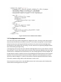
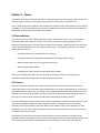
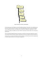
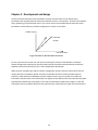
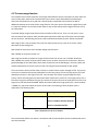
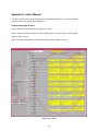
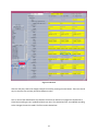
Management of a Nested XML Database
through Graphical User Interface
CHARLIE
WANG
Master of Science Thesis
Stockholm, Sweden 2008
Management of a Nested XML Database
through Graphical User Interface
CHARLIE
WANG
Master’s Thesis in Computer Science (30 ECTS credits)
at the School of Engineering Physics
Royal Institute of Technology year 2008
Supervisor at CSC was Henrik Eriksson
Examiner was Lars Kjelldahl
TRITA-CSC-E 2008:099
ISRN-KTH/CSC/E--08/099--SE
ISSN-1653-5715
Royal Institute of Technology
School of Computer Science and Communication
KTH CSC
SE-100 44 Stockholm, Sweden
URL: www.csc.kth.se
Abstract Test parameters for radio base stations are stored in XML‐databases. This is a good method to store information in a logical way. But it is complicated for the user to update it when the information is spread over different files in a nested file‐system. The system is handled by the version handler ClearCase which implies that there are multiple versions of the database which further complicates the update task for users. A graphical interface is developed and designed in Perl and Perl/Tk, which fetches and merges together the xml‐data and displays the information in a way that is easy for users to overview and search. It also enables the user to update information for multiple files at once. The ClearCase tasks as check in, check out and labeling files are handled automatically by the interface. The focus of this project is the user friendly perspective. Hantering av en nästlad XML‐databas via ett grafiskt användar‐
gränssnitt Sammanfattning Testparametrar för radiobasstationer är sparade i XML databaser. Detta är en bra metod att spara information på ett logiskt sätt. Men det blir komplicerat för användare att uppdatera databasen när informationen är utspridd över olika filer sparade i ett invecklat filsystem. Filsystemet hanteras av versionshanterare ClearCase, vilket medför att det finns flera versioner av databasen som ytterligare komplicerar informationsuppdateringen för användare. Ett grafiskt användargränssnitt har utvecklats i Perl och Perl/Tk. Det hämtar, slår samman och visar informationen på ett överskådligt sätt som gör det lätt för användare att göra sökningar. Användargränssnittet gör det också möjligt för användare att uppdatera informationen, som finns sparad i flera olika filer, på samma gång. ClearCase‐uppgifterna som checka in, checka ut och labla filer hanteras automatiska av gränssnittet. Fokusen för hela projektet har varit användarvänlighet. Acknowledgment I would like to express my gratitude to my supervisor, Thomas Helgeson at Ericsson for his introduction, guidance, consultations and countless valuable discussions throughout the project. I wish to thank my supervisor, Henrik Eriksson at Royal Institute of Technology for his support and guidance regarding the theoretical elements in this project and the project report. I would like to thank John Grenholm at Ericsson for giving me this opportunity to conduct this thesis work at Ericsson. I have benefitted from Robert Roséns valuable comments regarding the project report. At last, but not least I owe my loves to my family, especially my mum Yimin for always being supportive and encouraging, also my late grandfather Liang Si Ning for had woken up my interest for science at my early childhood. Charlie Wang Definitions and Abbreviations Configuration – XML‐files with same root node. GUI ‐ Graphical User Interface HCI – Human Computer Interaction Node – Start tag and end tag including the attributes and the string value between the tags but excluding any other nodes within the start tag and the end tag, the basic element of an xml‐file. OSE – Operating System Embedded RBS – Radio Base Station Tag – String unit that starts with “<” and end with “>”. Tag String – The text that is contained between the brackets in a tag. Table of contents Chapter 1 – Introduction ........................................................................................................................... 1
1.1. Background .................................................................................................................................... 1
1.2. A statement of the problem .......................................................................................................... 1
1.3. Development environment ............................................................................................................ 2
Chapter 2 ‐ Theory .................................................................................................................................... 3
2.1 Data collection ................................................................................................................................ 3
2.2 Persona ........................................................................................................................................... 3
2.3 Interactive design ............................................................................................................................ 4
3.1 The database ................................................................................................................................... 5
Chapter 4 ‐ Development and design ..................................................................................................... 10
4.1 The new merge function ............................................................................................................... 12
4.2 Display ........................................................................................................................................... 14
4.3 Editing ........................................................................................................................................... 18
4.4 Saving ............................................................................................................................................ 19
4.5 Extra functions .............................................................................................................................. 20
Chapter 5 ‐ Result ................................................................................................................................... 21
5.1 Necessary features needed to be implemented ........................................................................... 21
5.2 Future development and improvements ...................................................................................... 22
Bibliography ............................................................................................................................................ 23
Books ................................................................................................................................................... 23
Articles ................................................................................................................................................ 23
Websites ............................................................................................................................................. 23
Appendix A– User’s Manual .................................................................................................................... 24
Chapter 1 – Introduction 1.1. Background The work in this master’s thesis has been carried out in collaboration with Ericsson (Radio Subsystem Functional Verification) as a part of a larger software development project. The result of this larger project is a test system, which is used for functional verification of software inside different radio products that together form a Radio Base Station (RBS). The radio products incorporate an operating system called Operating System Embedded (OSE). The OSE operating system is priority based and uses signals to communicate between different processes. From the testers’ point of view, the signals consist of sets of data strings, which are called parameters. The signals themselves are grouped together to form interfaces. The information about the parameters is stored by Parameter Database inside the test system. In the Parameter Database the parameters are grouped by interface whereas the groupings by signals are omitted. The aim of my project is to produce a Graphical User Interface (GUI) which makes accessing and editing of the Parameter Database easier. 1.2. A statement of the problem Today, there are many different ways to store a database, and these ways of storing and structuring data are carefully chosen to optimize one or more aspects of data usage. Therefore, some of the aspects are compromised in order to achieve the main purposes. In our case, the main limitation that determines the structure of the database is the properties of the data itself and usage of the data. The data contains signal parameters that are basically data strings with an identifier. Together, the parameters are gathered to form an interface. Here, the developers of the test system have decided to store the interface as an XML‐file. However, the files cannot be edited directly, since a file handler called ClearCase is used to add an extra dimension to the database. Several problems arise when the user wants to update the content of the database. The first challenge is to find the right file path and right file. Secondly, after finding the right file the user has to determine the correct place in the file to edit. Lastly, the ClearCase commands need to be executed in order to mark the file as a new one and not conflict with the old version. All these steps makes the data update task a very cumbersome one. Since the structure of the database was fixed we needed to solve the problems by creating an intermediate layer, thereby making the presentation and setting of the database a more manageable task. 1
Figure 1 Extract from one XML-file in the database
1.3. Development environment The result of this project will be integrated into a bigger test system. This larger system will provide a test environment with better overview for the users. In this case the user group is consists of about twenty function testers working with software verification. They have extensive knowledge about functionalities of the software they are testing. The users often have an engineering background with basic understanding of programming. In the beginning of this project the users had little knowledge about the test system because it had not been launched. The users were familiar with the content of the Parameter Database, but they had not worked with it in a database environment before, so a user‐friendly approach had to be adopted. The limited experience makes it hard for the users to give feedback and request features of the Parameter Database. The lack of information from the users makes it difficult to create adequate user profiles (persona) to base the design on. Instead, I have chosen a theoretical approach to build user context information, based on design used by other developers in earlier cases. The test system is written in Perl, I have decided to also use Perl in this project, which facilitates the communication and integration to the system. 2
Chapter 2 ‐ Theory The aim was to perform the whole project from a Human Computer Interaction (HCI) point of view. This section will give a theoretical overview of the work that has been done in the field of HCI. HCI is a wide concept that includes all the methods that could be used to make product as user‐friendly as possible. Two of the methods that are commonly mentioned are creation of persona and interactive design, both of which will be described in detail below. 2.1 Data collection The common factor in all the different working modes is that they start at the user, by collecting as much information about them as possible. This involves an extensive study regarding the user’s background, working pattern and work context. How this information is obtained varies from project to project and often depends on the size and type of the project. The following methods are commonly employed, taken from [5]: ‐
Interview with the users outside of their use context ‐
Information about users supplied by stakeholders and subject matter experts ‐
Market research data such as focus groups and surveys ‐
Market segmentation models ‐
Data gathered from literature reviews and previous studies Out of these available methods, it was decided that we should utilize the user interviews, the information supplied by subject matter experts and literature reviews. 2.2 Persona After the information about the user had been gathered there existed several possibilities how to present and analyze it. One commonly used method today is to create so‐called personas. A persona is a detailed model of a typical user. This model is personified and based on the observations of real users. Although the persona is personified it still has to represent the typical behaviors of a group of users. In this way it can reflect crucial issues that need to be handled during the design process. The main advantage of using personas is that it helps the developers model the needs of end users, and also creates sympathy for those needs [6]. Another benefit of using personas is its re‐usability, especially within large software enterprises. When a new software project starts designers can look through the archives of personas and look for those personas that describe the same type of user that will benefit from the new project. The benefits of using personas that we mentioned above is obviously based on the quality of the personas create for the purpose. There are many criteria a persona has to fulfill in order be usable. One of the criteria is goals [5] which motivates why the user behaves in a certain way. This helps the 3
developers to get a deeper understanding of the problem they have in hand and to find a solution of the problem that fits better into the user context. A standard reference of the subject of personas by Cooper and Riemann [5] describes the different types of goals a persona should mediate. The two categories developed are user goals and nonuser goals. The user goals are then divided into different levels of concretization. Life goals of the user are on the most abstract level, which describes what drives user to do things. Experience goals models how the user wants to feel while using the product. The most concrete user goals are the end goals which concern the actual problem the user wants to be solved by using the product. The nonuser goals deal with the layer between the product and end user. Sometime products have to pass a middleman to eventually reach the end user. This middleman could be a purchaser, a Head of IT, the Head of Department or any other such important participant. Those people have their own goals that they want to fulfill, for instance to facilitate IT‐management, to increase productivity or lower the cost. Which category of goals that should be most important, the user‐ or nonuser goals, depends on the property of product being developed. If the product in question is an enterprise product, the persona should stress the nonuser goals, whereas for a consumer product the persona should emphasize user experience goals. 2.3 Interactive design Another commonly used term within HCI is interactive design. It is a method that involves the user throughout the whole software project from the data collection to the final product. This method allows all participants of a project to start working directly from their own perceptions of what the project is about. The solutions are then discussed between all the stakeholder of the project and statements about improvements are made for all the parts of the project. The process goes on until it reaches a state that satisfies all the stakeholders. For this method to succeed close communication is needed between the different sectors of a project. This is often handled by one person, who is can be titled interaction designer. This interaction designer takes the role of a communicator between different parts of the project sometime they can even take the role as the project leader [4]. It is important that the interaction designer has good overview through the whole design process from sketch to the final product. The communication between different project parts in it most basic form can be as simple as conversation between one developer and an end user. In large software projects and software enterprises there often exists a whole user interaction team that works specifically on these issue and acts as consultants to different ongoing software projects [5]. To conclude ways of working within HCI are heuristic but always start from the user. It is also an iterative process that goes back to the user during the design. 4
Chapter 3 – System descriptions This chapter will describe the structure of the whole system 3.1 The database Since the main goal of the project is to create a user friendly GUI for access to the database we first need a clear picture of the structure of the database. 3.1.1 Database Structure The Parameter Database is located in a regular file‐system; it contains parameter values needed for tests of RBS. The file‐system is divided according to different physical test products. Each test product is then divided into different product types. Every product type has its own file folder contained in its test product folder. Each product type folder then contains the parameter data for the test product the folder represents. There are different kinds of parameter data regarding different configuration parts, parameters of same configuration is therefore grouped together and saved as xml‐files. The configuration parts are the following: ‐ Interface configuration ‐ Test case configuration ‐ Test system configuration ‐ Code configuration ‐ Group configuration ‐ Product information configuration One configuration for a specific product type is not only contained inside the product type folder, but also in folders higher up in the file‐tree hierarchy. This is because there are configuration data that are common for all product types under a test product and those data are stored in the common folder under the test product folder. Other configuration data that are common for all test products are contained in the common folder direct under the root folder. 5
ParameterDB Common Product Common Product type Figure 2 Structure of the file system Database
The filesystem where the Database is stored is handled by ClearCase. Every time a file is modified a new version of it will be created. This results in a multi‐versioned Database. Which version of the Database users see depends on how the users define their own ClearCase configuration specification. It is also possible to set labels on the different versions of the file and make ClearCase choose a file version with a specific label. After reviewing the database a decision was made to only work on the interface configurations, due to time limitation and also because interface configurations are the most complex structure among the all configurations in the Parameter Database. Once the problems are solved for the interface configurations it is easy to adapt the solution on all the other configurations. 6
3.1.2 Structure of the interface configurations The interface configurations are properly nested xml‐files. The basic element of the database is strings, which are wrapped around within xml‐tags. Between a start tag and end tag pair can either contain an under node or a data string but not both. The xml‐file‐is designed to follow a tree‐structure. The example file can be decomposed into a diagram. Each box in the diagram represents a node. The relationship between nodes can either be parent‐child relationship or sibling relationship. In the diagram we can also see function of some special xml‐nodes and attributes, they are displayed as identifiers to their parent node instead as independent nodes. The identifiers are, in decreasing prioritize order: ‐ The name node: <name>…</name> ‐ The type attribute: <... type=”…”>…</…> ‐ The id attribute: <… id=”…”>…</…> To summarize; in order to find a specific string in an interface configuration we have to know the path from the root node to itself, and if there several sibling nodes with the same tag we also have to know the node identifier. There are many limitations to our work. Time is major factor that needs to be handled in a way that balances the user friendliness of the GUI and the functional result of the project. <interfaces> <interface> <name>interface_A</name> <signals> <prefix>A</prefix> <prefix>B</prefix> </signals> <siglib> interface_A </siglib> <sigfiles> <file>../A</file> <file>../B</file> </sigfiles> <capability type="AAA"> <signame>BB</signame> <cap id="1"> <name>CC</name> <length>10</length> </cap> <cap id="2"> <name>DD</name> <length>10</length> </cap> </capability> <parameter> <name>AAA</name> <value>3</value> <range>1,2,3,4,5</range> </parameter> <parameter> <name>AAB</name> <value>3</value> </parameter> </interface> </interfaces> Figure 3 The Interface
Configuration Structure 7
interfaces
interface
name: interface_A
signals prefix string: A siglib string: interface_A prefix string: B file string: ../A sigfiles
parameter
name: AAA
File string: ../B capability type: AAA signame string: BB value string: 3 cap name: CC id: 1
cap name:DD id: 2 length string: 10 length string: 10 range string: 1,2,3,4,5
Figure 4 Tree Structure of Interface Configuration
3.1.3. Situation today today To create a profile of a typical user we began with an investigation of database usage and updating patterns today. The tasks within the database are to change and add new data to the database. This involves several steps, the complexity of which depends on the structure of the database. Firstly, the user has to know which product type the change of information is to be applied to. Secondly the user has to know in what level the information is contained. Lastly, the user identifies the right xml file to update. This is done either in a graphical user interface for the file handler or in a command line interface. Once the file has been found the user has to begin to deal with ClearCase issues, which mainly consist of check out, check in and set label to the files. In order to edit a file, it needs to be checked out. When the file is open the user needs to find the exact line to update the information. Thereafter it needs to be saved, checked in and have a label set. 8
All of the procedure described above needs to be repeated if the user needs to update different information. It is not only a lot of work; it is also easy to make mistakes. What we want to do with this GUI is to hide much of the work that has been described above from the user and let them concentrate on the actual task which is to view and update the database information. 9
Chapter 4 ‐ Development and design From the previous description of the Database structure and user tasks we can identify three parameters that uniquely determine the exact interface the user is interested in. Those are the interface name, product type and ClearCase version. This can be seen as a three dimensional space with these parameters as axes and every interface configuration is a point in the space. Product Type ClearCase Version Interface name Figure 5 Parameters that determine an interface
For every instance of time the user will only be accessing one version of the database, I therefore choose to begin with working only with the product type and interface name parameters and let the Database version be chosen by the user’s own configuration specification. When we have a product type and an interface configuration chosen, there are exactly three files we need to look into: the product specific interface, the product common interface and the common interface, as described in the Database structure chapter. But this is not as simple as to collect the information, because some of the information can appear in two different files with exact the same path and identifier but different string value. In this case the information needs to be merged, in a way the information from the product specific file are prioritized over information for higher up in the hierarchy. 10
To understand the merge procedure let us take a look at the following examples. <interfaces> <interface> <name>TR_CDCI</name> <parameter> <name>Freqx</name> <valid>1::3</valid> </parameter> <process>1</process> </interface> </interfaces> File with higher priority + <interfaces> <interface> <name>TR_CDCI</name> <parameter> <name>Freqx</name> <default>2</default> </parameter> <parameter> <name>Bandwith<name> <valid>1::20</valid> <default>15</default> </parameter> <process>3</process> </interface> </interfaces>
File with lower priority = <interfaces> <interface> <name>TR_CDCI</name> <parameter> <name>Freqx</name> <valid>1::3</valid> <default>2</default> </parameter> <parameter> <name>Bandwith<name> <valid>1::20</valid> <default>15</default> </parameter> <process>1</process> </interface> </interfaces>
Result after merge Figure 6 Merge example
The basic criterion to merge two files is that they have the same root node. The result of a merge process is a xml‐file containing nodes from the argument files where each node keeps it original path in the xml structure. Identical nodes that appear in both of the argument files will only appear once in the result and it is the node with higher priority that overwrites the node with lower priority. In the example the <process>‐node in the lower priority file gets overwritten by the <process>‐node from the higher priority file. Such a function already exist in the test system, it is the Perl module called XML::Merge. The XML::Merge works exactly as we have described. One thing that we need to notice here is that the result files from the merge process is memory‐less, which means that once we get the result file we don’t have any clue about where each node originates from. From the discussions with the developers we get to know that the source information for each node helps the user to get clearer picture of database and facilitate the work, and needs to be displayed in the GUI. The choices were to make modifications to the XML::Merge module or build a new merge function. After reading through the source code of XML::Merge, I decided to rebuild the merge function. The XML::Merge is a comprehensive module with a lot more functions than our merge requirement. The code was also written in a nested way and hard to get an overview of. This makes the modification task equally hard as the rebuilding task. Another problem with XML::Merge is the process speed, which users perceive as slow. 11
4.1 The new merge function The rebuild function needs to perform xml‐merge and handle the source information for each node. The source information needs to be stored and the ways to store it were discussed with the developer. Structures discussed were array and hash. We eventually reached the final resolution to add an additional attribute to the result of the merge function. Since the source information regards every node it is natural to attach it to the node, which makes it easy to find and naturally integrate with the rest of the information. From XML::Merge we get some ideas on how to handle xml files in Perl, for it is an xml‐parser. In our case we need to have a parser which handles Xpath expressions which we will need to search through the xml‐structure. The following xml parsers were tested and evaluated, by their abilities and speed. XML::twig Creates a tree‐structure of the xml‐file, allows access to only a part of an xml‐file, which decreases the processing time. XML::XPath the xml‐parser which the XML::Merge was built upon XML::LibXML an xml‐parser written in C XML::twig was suitable to handle very large xml‐files which was not our case. The XML::XPath and XML::LibXML have similar functions which makes it easy to switch from the one to the other. We have good knowledge of how XML::XPath works from the previous use of XML:Merge in the test system and therefore decided to let the first version of the new merge function be based on XML::XPath. The tree‐structure of the xml‐file makes recursion a natural choice to work through the file. The priority issue can be viewed as that we only add nodes from the low‐priority file into the high‐priority file if the node does not exists in the high‐priority file. We use Depth First Search to get through the lower‐
priority xml‐file and along the way build up the XPath expression to search for in the high‐priority file. If the search using the result does not give any result then we know for sure the node does not exist in the high‐priority file and should be added. Before the node is add into the high‐priority file a level‐attribute is added to it, which tells about the source of this node. The meaning of level‐attribute value is explained in the following table. Level‐value Meaning Nodes without level‐attribute Exits in a Product type level file 1 Exits in a Product common level file 2 Exits in a common level file Table 1 Explanation of the level attribute
The level‐attribute affects the node it is attached to and all its descendants unless the descendant has it own level‐attribute. 12
If we turn to the merge example that we took up earlier in the text, and apply our new merge function to it the result will be the following: <interfaces> <interface> <name>TR_CDCI</name> <parameter> <name>Freqx</name> <valid level = “1”>1::3</valid> <default>2</default> </parameter> <parameter level = “1”> <name>Bandwith<name> <valid>1::20</valid> <default>15</default> </parameter> <process>1</process> </interface> </interfaces> We used the Benchmark module to compare the new merge function with the old one. XML:Merge: “the code took: 4 wallclock secs ( 3.28 usr + 0.04 sys = 3.32 CPU)” Our Merge function: “the code took: 3 wallclock secs ( 3.02 usr + 0.04 sys = 3.06 CPU)” The new merge function improves the processing time by 25%, but the processing time was still a problem, since the benchmark only concerns one interface with one product type, during the actual use there maybe over ten product types to be processed at once, which means a waiting time around 30 seconds for the user. That is not acceptable. By modifying the function through LibXML parser instead we have come to the following result: Our Merge function using LibXML parser: “the code took: 0 wallclock secs ( 0.09 usr + 0.00 sys = 0.09 CPU)” This is an acceptable result. 13
4.2 Display The next phase was to present the merged information to the user. In the discussions with the developers, they have explicitly expressed the need of viewing interface information for several product types at once. Different solution, were sketched on paper and discussed closely with the developers. The solution was to implement tabs, textboxes and tables. Tabs were the first item that came up, the idea is to have each product type to be contained in its own tab in the main window, and the user could easily switch between the tabs. The problem with this solution was that the user will not be able to view several product types at same time. The next attempt was to have one textbox for each product type and put all the text boxes in one window. We get the overview with this solution, but there is still a lot of relationship information embedded between interface files that will be lost. I. e. the product common information will appear in every textbox but it will not be clear that it represents exactly the same information. This tells us that we need a more structured way to represent the merged information. The last solution was to display the information inside a table; this is because the table provides a natural way to structure up the data by put one text string in each table cell. The columns in the table provide clear separation between different product types and the comparable data from different product types can put into the same row in the table. This solution also fulfills the users’ wish to work with something familiar which according to them is an Excel worksheet. If all information from each product type is displayed, a lot of redundant information will appear on the screen. For example, many comparable nodes have exactly the same tag around its string value, it is therefore unnecessary to display the tag string more than once. What I did here was to separate the tag string from the actual string value for each node. The first column in the table is used to display the tag strings and the rest columns displays only string values insides the nodes. The splitting between the tag and string of each node takes out the single strings, which is the most basic element of the Database, and result in only one text string will be displayed in each cell. This makes easier for the user to read the data. With this separation the brackets around the tag strings are also omitted which further enhances the readability for the users. One consequence of stripping down the data into its most basic parts and display them separately is that the parent and child relationship between nodes will be lost. To prevent the information loss we used an indentation to highlight a deeper level node in the tree‐structure, the indentations are put before tag strings in the first column. Users have also expresses wishes to display the information in a manner that resembles the appearance of xml‐files and it is also fulfilled by the indentations. Some nodes have attributes inside the tag bracket; we have chosen to display the attribute together with the tag string which increases the resemblance to xml‐files. The level‐attribute can not be displayed together with the tag string in the first column, because it is extra information added by our merge function and it is not common for all of that product type. The level‐attribute should therefore be displayed separately for each and every cell in the table. But to put the level‐attribute directly after the string value in each would make the table look very messy and it could also confuse users to believe that the level‐attribute is something that exists in the Data Base. The 14
purpose of the level attribute is to hold track on the source of each node, so instead of displaying it explicitly we chose to let it decide the background color of each cell. In this way we got around the problem with the messiness that comes with the extra attribute; the different colors also make it easier to see the source difference between nodes. With the display structure ready we also need to decide the orders between the sibling nodes. As an interface configuration can contain up to hundreds of nodes it can be difficult for the users to find a specific node if the nodes are not consistently ordered. We order the nodes exactly as how we identify the nodes, the rules are the following. 1. Sibling nodes are order by there tag string, with one exception on the name node which always comes first among its siblings and directly after its parent node, since the name node identifies its parent node. 2. Sibling nodes with the same tag string are ordered by their identifier. 3. Sibling nodes with the same tag string but without identifier are ordered by their string value. The function that handles data display is illustrated by the following diagram. 15
Fill the gaps with first node from
the corresponding list
The loop runs until the sorted
list becomes empty
Rest of the
list
Refilled list
Pop the first nodes that have same
tag and id
Sort the refilled the list
tag string Sorted list
Write out the node
tag and possible
strings value in
the display table
Pop the first node
1 2 3
n 3
n Sort each list
1 2 Return the top level
nodes of the each
document
Start a recursion if the nodes
have under nodes
Figure 7 Description of the display function
16
We sum up the display part with the following example. Input files: Product type: 1 Product type: 2 Product type: 3 <interfaces> <interface> <name>TR_CDCI</name> <parameter> <name>Freqx</name> <valid level = “1”>1::3</valid> <default>2</default> </parameter> <parameter> <name>Bandwith<name> <valid level = “1”>1::20</valid> <default>15</default> </parameter> <process level = “2”>1</process> </interface> </interfaces> <interfaces> <interface> <name>TR_CDCI</name> <parameter> <name>Freqx</name> <valid level = “1”>1::3</valid> <default>3</default> </parameter> <parameter level = “1”> <name>Bandwith<name> <valid>1::20</valid> </parameter> <process level = “2”>1</process> </interface> </interfaces> <interfaces> <interface> <name>TR_CDCI</name> <parameter> <name>Freqx</name> <valid level = “1”>1::3</valid> <default>1</default> </parameter> <capability type="AAA"> <signame>BB</signame> <cap id="1"> <name>CC</name> <length>10</length> </cap> </capability> <process level = “2”>1</process>
</interface> </interfaces> 17
Result: interfaces Product type: 1 Product type: 2
Product type: 3 interface name TR_CDCI
TR_CDCI
TR_CDCI capability type="AAA" cap id="1" name length cc 10 signame BB parameter Bandwith
Bandwith
15
1::20
1::20
Freqx
Freqx
Freqx 2
3
1 valid 1::3
1::3
1::3 process 1
1
1 name default valid parameter name default Table 2 The white color of the cells shows the information coming from product type specific interface
configuration, the yellow color corresponds to the product common interface configuration and the blue color
shows that the source is common level interface configuration. The grey colored cells mean that the nodes do
not exist for those product types.
4.3 Editing The editing part is based on the table where all the data is displayed; every string value is therefore put into a Perl/Tk entry object before it is added to the table. To avoid unintended editing all the entries are set to un‐editable mode. Here we need to stress the importance of the identifier that enables us to search back to the node in the original file, and therefore all the cells containing identifiers should not be editable by the user. An array is used to keep track on whether each cell in the table is editable or not. The array also stores XPath expression which let the GUI have direct access to each node. When the table displays interface data for several product types there are always some data items that are common for all the product types and some data are common for product types that belong to same product area. This means that there are cells in a row with same source. If a user put different string values into cells with same source, it will be impossible for the GUI to determine which string to set in the database. To avoid this ambiguous situation we put the source information of each cell into the array. Every time the user changes the string value in a cell the GUI will compare its source with all other cells’ source in the same row, if equality is found the string value in the corresponding cell will also be changed. 18
To optimize the change procedure we used an array to keep track on the original string value of each cell. Every time a user edits a cell, the GUI will compare the edited string with the original string, if there is difference between the strings the cell will be put in the list of changed cells. When the GUI does the actual update it only has to go through the cells in the list instead of re‐dumping entire xml‐files. The array of original string value and the list of changed cells together made it possible to develop an extra undo‐function to the GUI, which undoes the changes made by the user. 4.4 Saving To make the actual changes in the database our GUI needs to handle ClearCase issues, because the entire database is handled by ClearCase. Through discussion with developers and users we get to know that most users deal with ClearCase on daily bases in their work. But sometimes they still feel frustration over having to manually deal with these issues, especially when many files need to be updated. By letting the GUI handle ClearCase issues for many files simultaneously, a large improvement in effectiveness will be experienced by the users. Also, errors will decrease and user satisfaction will probably be higher. Therefore ClearCase handling is an important part of the GUI, especially as it acts as an incentive for the users to start using the GUI. From the user point of view the saving part is as simple as one button click. The user needs to choose if he/she wants to set label on changed file and if the changed files should be checked in again, this is solved by two checkboxes. The GUI uses an already existing module in the test system build to handle ClearCase and runs everything in background hidden from the user. For detailed description see appendix [A] 19
4.5 Extra functions When many product types are chosen to be seen simultaneously the table becomes very wide with many columns. It is hard for the user to concentrate on the specific row he/she is working on especially when the table is scrolled in a sideways direction. The users therefore see the possibility to mark multiple rows as an important aid to improve the working experience and efficiency. The most natural way to do the marking is to change the background color of the rows, just as in Excel. But in our case the background color is already used for displaying the source of cells and can therefore not be changed. Instead we chose to change the border size of the rows that need to be marked. To mark a row user just needs to double click somewhere in the row. The users have also expressed the need to navigate through the display table using the keyboard as a complement to mouse, because when editing most work is done from the keyboard. It is therefore tedious and not very efficient to switch between mouse and keyboard. We therefore made it possible for the user to change the cell focus in the table using control‐keys and arrow‐keys. The ideal solution would be to only use arrow keys, but doing so would collide with the functionality that moves the edit cursor inside each cell. 20
Chapter 5 ‐ Result The main result of this project is a complete GUI for viewing and editing existing data in the database, with possibility to work with multiple product types simultaneously. The GUI also provides groundwork for future improvement and development to build upon. The result was demonstrated to the future users which consist of the people who are involved in the test system’s early development phase and the people who do not have any knowledge of the test system. The feedbacks are overall positive, mainly because of the overview the GUI creates. There were also some spin‐off results from the project. The new merge function has reduced the process time by 98% compared with the old XML::Merge and it is being integrated into the test system and used by other features. The display function could also be reused for other parts of the test system where xml‐data need to be presented. But for the GUI to fully replace the manual editing of the database some more features will need to be added. 5.1 Necessary features needed to be implemented The editing function of the GUI is now limited to the data that already exists in the database. When new information needs to be added or old information needs to be removed a user has to do so manually in a text editor. Features such as add and remove nodes were sketched during the design phase, but due to time limitations they were not implemented. The proposed solutions are the following: ‐ Add node The first thing a user needs to know when creating a new node is where to create it. Basically, a creation consists of determining the parent node, which the new node will be put below. When the parent node is found in the display table the user can double click on its tag string which will result in the creation of an empty row underneath. Values of the new node could then be added into the empty row. Another parameter a user needs to determine is the file‐level the new node to be saved in, as for the display part this parameter is reflected by the background color of each cell. The consistent solution here is to let user set the background color of the cells and hence determine the file‐level. If no background color is set the new node should adopt the file‐level of its parent. Before the node is added to the database the GUI should also check uniqueness of the node to prevent ambiguities inside the database. ‐ Remove node Ideally, any cell in the display table should be removable by right clicking on it and choosing the remove option in the popup menu. The GUI will check the effects after the cell is removed. The followings are the possible effects: ‐
If the node has child nodes, then all its descendant nodes would be removed. ‐
All the nodes in the table that shares the same source as the removed node would also be removed 21
‐
If the removed node is an identifier the GUI should raise a warning that the identifier cannot be removed alone, the removal of the identifier node will results in the removal of its parent node and all the descendant nodes of the parent node. ‐
If the content of the removed cell is the tag string then all the nodes in same table row will be removed. Other features that have not been thought over in detail but are important for the usability of the GUI are the followings: ‐
Creation of new XML‐files in the database, either from scratch or base on existing files in the database. ‐
More comprehensive ClearCase handling that allows users to view different version of the database. This basically means adding the third axis to the GUI and makes it possible for users to access everything in the Database. ‐
Add handling of other configuration parts in the database to the GUI. 5.2 Future development and improvements In a broader perspective the role of this GUI can be widened to including database optimization tools. An example of this is that there may appear redundant data between interface configurations for several product types under same product, and then the GUI should indicate that redundancy to the user and help said user to move the information form the product type level files to one product common level file. Generally the GUI should support copy and move of information between different files in different versions of the database. From the editing point of view a lot of standard editor functions could be build into the GUI such as unlimited undo‐ and redo‐function and a string search function. The possibilities are unlimited but it will always be a question regarding the balance between the work load put into the system and the benefits received from it. 22
Bibliography Books [1] Lidie, S. & Walsh, N. (2002). Matering Perl/Tk. O'Reilly [2] Wall, L., Christiansen, T. & Orwant, J. (2000). Programming Perl , Third Edition. O'Reilly [3] Silberschatz, A., Korth, H. & Sudarshan, S. (2005). Database System Concepts, Fifth Edition, Chapter 10. McGraw‐Hill Articles [4] Lantz, A., Artman, H. & Ramberg, R. (2005). Interaction Design as Experienced by Practitioners [5] Cooper, A. & Reimann, R. (2003). About Face 2.0: The Essentials of Interaction Design, Chapter 5. Wiley Publishing, Inc. [6] Pruitt, J. & Grudin, J. (2003). Personas: Practice and Theory Websites http://search.cpan.org/~msergeant/XML‐XPath‐1.13/XPath.pm http://search.cpan.org/~pip/XML‐Merge‐1.2.565EgGd/Merge.pm http://www.w3.org/TR/xpath http://xmltwig.com/ 23
Appendix A– User’s Manual This GUI is used for access and update data in the parameter database. The GUI is located at /vobs/iov/terass/func/magic_gui/magicGUI.pl Load product types to view Step 1: Choose the interface to access. (Figure 8, mark 1) Step 2: Select one product and one or more product types to view the chosen interface with. (Figure 8, mark 2 and 3) Step 3: Push the load button to view the information chosen (Figure 8, mark 4) Figure 8 View mode
24
It is possible to mix different product in the view table. If you want to view more product types in the table just repeat the steps two and three. The interface information for the newly chosen product types will be added to the end of the view table. The table is restricted to display five product types simultaneously and if there are more than five product types chosen you can view information for the hidden product types by scrolling the horizontal scrollbar. Once the product types are chosen, they are stored in the program. This enables the possibility to view different interface information for the chosen set of product types. By choose another interface in the interface dropdown menu (Figure 8, mark 1) and then press the load button (Figure 8, mark 4) view table will update its content for the newly chosen interface. To clear the product types that are chosen click the Clear Button (Figure 8, mark 6) and this will also result in the clearing of the table content. Table order The data in the table is ordered by following rules: ‐The nested structure of the xml files, which means the top node always goes before its under node. Relationship between a top node and its under nodes is highlighted by indention. ‐The name node that identifies its top node always follows its top node. ‐Nodes with the same top node are ordered with alphabetic order re the node’s tag string ‐Nodes with same tag string are ordered by its identifier The identifiers are, in decreasing prioritize order: ‐ The name node: <name>…</name> ‐ The type attribute: <... type=”…”>…</…> ‐ The id attribute: <… id=”…”>…</…> The meaning of the background color of each table cell
The background color of each cell tells users about the source of data contained in that cell. White means the information is common for all products in the database. Yellow means the information is common for one specific product group. Grey means the information is product type specific. 25
Edit mode The editing part is restricted to the existing data, which means that it is not possible to delete existing parameters and add new parameters. Some of the existing data are of the identifying character and therefore can not be edited. Press the Edit (Figure 8. mark5) button to switch the view table to edit mode, which means the texts in the editable cells become editable and their color change to black. Also notice that all the cells that contain identifier information remain not editable. With several product types chosen the information displayed in the cells of white color is common for all the product types and yellow ones are common for the product types under same product. Therefore when you edit that information in one of the cells all other cells that display the same information are also changed. Once a cell is highlighted, it is easy to use Control‐Arrow keys to navigate through the table. Every change made in the table is remembered by the program and could be easily undone by pressing the undo button. Here we need to raise a warning flag for this button, because it will undo all the changes made in the table and switch back the table to the view only mode with no possibility for reverse. For the changes to be registered by the program the user needs to change the program focus from the cell that just has been edited to a new cell. 26
Figure 9 Edit mode
After the edit part is done the changes need to be saved by pressing the save button. There are several ways to save the files and they all lead to different results. Case 1: none of the radio buttons are checked. The files that need to be changed are checked out in ClearCase according to users’ predefined check out rules. The checked out files are modified according to the changes the user has made. The files remain checked out. 27
Case 2: the ‘Set Label’ radio button is checked. (Figure 9, mark 2). The procedures here are exactly the ones in case 1, plus for every file that is changed a ‘Set label’ popup menu will appear. (Figure 10) Figure 10 Label Selection Menu
User can choose to use the current label of the file, which is pre‐entered when the menu pops up, or choose a label in the list, that contains all the labels in the vob, or directly type the label in the text field. By choosing the files current label means the label will be moved from the old version to the edited version. But it is not always possible to move a label because some labels are locked to a specific file version. If the label to set does not exist in the vob, a new label type will be created. Case 3: the ‘Check In’ radio button is checked. (Figure 9, mark 3). The procedures here are exactly the ones in case 1, plus after each file is modified it will be checked into ClearCase according to users predefined check in rules. No merge will be done in this case. Case 4: both ‘Set Label’ and ‘Check In’ radio buttons are checked. This case combines the procedures of case 1, 2, and 3. Extra functions
Mark Row: By double click any cell in the table the entire row that contains the cell will be marked. Double click again to unmark. 28
TRITA-CSC-E 2008: 099
ISRN-KTH/CSC/E--08/099--SE
ISSN-1653-5715
www.kth.se