1
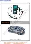
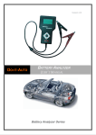
-1- BESA -12P M User’s Manual ___________________________________________________________________________________ BESA -12PM Battery Electrical System Analyser -1- User’s Manual Version PM1504 R & J Batteries Version PM1504 BESA -12PM User’s Manual -2- Table of Contents 1.0 Introduction-----------------------------------------------------------------------------------------1.1 BESA 12PM (Battery Electrical System Analyser) -------------------------------------------------3 1.2 Specifications--------------------------------------------------------------------------------------------------4 2.0 Safety Measures-----------------------------------------------------------------------------------2.1 Safety Precautions--------------------------------------------------------------------------------------------5 2.2 Other Precautions---------------------------------------------------------------------------------------------6 3.0 Working with Batteries--------------------------------------------------------------------------7 4.0 The Battery Electrical System Analyser------------------------------------------------------4.1 BESA 12PM----------------------------------------------------------------------------------------------------- 9 4.2 Key Functions---------------------------------------------------------------------------------------------------10 4.3 Functions of Individual Key-------------------------------------------------------------------------------10 5.0 Initial Setup ----------------------------------------------------------------------------------------5.1 5.2 5.3 5.4 5.5 5.5 5.7 Paper Installation---------------------------------------------------------------------------------------------11 Setup Menu ----------------------------------------------------------------------------------------------------11 LCD Brightness-----------------------------------------------------------------------------------------------12 Printer------------------------------------------------------------------------------------------------------------12 Set Date & Time ----------------------------------------------------------------------------------------------13 PC Link----------------------------------------------------------------------------------------------------------13 Erase Memory ------------------------------------------------------------------------------------------------14 6.0 Battery Test-----------------------------------------------------------------------------------------6.1 Begin Battery Test (Automotive) ----------------------------------------------------------------------17 6.2 Battery Test for Motorcycle, Commercial Vehicle, etc. -----------------------------------------23 7.0 Other System Test--------------------------------------------------------------------------------7.1 Starter Test-----------------------------------------------------------------------------------------------------32 7.2 Alternator Test -------------------------- ---------------------------------------------------------------------35 Starts with No Load testing at 3,000 RPM------------------------------------------------------------35 Testing with electrical load at 2,000 RPM------------------------------------------------------------32 7.3 Grounding Test------------------------------------------------------------------------------------------------41 8.0 Stored Results ------------------------------------------------------------------------------------8.1 Recalling and viewing previous Test Results-------------------------------------------------------45 9.0 Printing the previous Test Result from memory---------------------------------------48 10.0 PC Link---------------------------------------------------------------------------------------------10.1 Installing driver -----------------------------------------------------------------------------------------------48 10.2 Printing Results from PC Printer------------------------------------------------------------------------53 10.3 Saving Results to PC----------------------------------------------------------------------------------------54 11.0 Warranty Information---------------------------------------------------------------------------11.1 Limited Warranty----------------------------------------------------------------------------------------------55 11.2 Limitations of Warranty-------------------------------------------------------------------------------------56 BESA -12PM Version PM1504 -2- -3- BESA -12P M User’s Manual ___________________________________________________________________________________ 1.0 Introduction 1.1 BESA-12PM (Battery Electrical System Analyser): The utilization of the latest advanced technologies in battery testing had enabled this Analyser to test batteries in any conditions. Testing procedures are made simple with quick, easy and repeatable results. Test Results can be printed directly on its’ built in printer. It can store up to 300 test Results in its memory for future references and they can also be transferred and saved in the PC for records management via an USB port link. The programs consist of: 1. Battery Test: Analyses the battery condition using microprocessor controlled testing methods without the need of fully charging it before test. The unit consumes very little current during testing hence the test can be repeated numerous times without worry of draining the battery and its results are highly accurate. Extremely safe as it does not create any sparks during clamp on and it takes less than 8 seconds to obtain the full analysed results of the battery being tested. 2. Starter Test: Checks the cranking effectiveness of the battery to predict when the battery will fail to crank a vehicle basing on voltage profiles with results and recommendations display. 3. Charging Test: This test checks the alternator charging condition during electrical loading at 2,000 RPM and without load at 3,000 RPM with results and recommendations displayed after each test. -3- 4. Grounding Test: Analyses the condition of the electrical return circuit contacts resistance which was connected to the engine or chassis body from the battery terminal with results and recommendations displayed after testing. R & J Batteries Version PM1504 BESA -12PM User’s Manual -4- 1.2 Specifications: Operating Voltage: 9V ~ 15V DC (max) Safety: Built-in reverse polarity protection. Analysing Capacity (Amps): Automotive, Commercial vehicle, Marine / Watercraft: CCA: IEC: JIS#: CA: 100A ~ 1700A 100A ~ 1700A 100A ~ 1700A 100A ~ 1700A EN: DIN: SAE: 100A ~ 1000A 100A ~ 1000A 100A ~ 1700A Motorcycle, Motor Scooter, Lawn Mover, Golf cart, Snowmobile: CCA: IEC: JIS#: CA: 40A ~ 600A 40A ~ 600A 40A ~ 600A 40A ~ 600A EN: DIN: SAE: 40A ~ 600A 40A ~ 600A 40A ~ 600A DC Volts Accuracy: ± 1% Reading Battery analysing time: Less than 8 seconds. Language: English only. Memory: Stored up to 300 Test results. PC connection: Through USB port. Printer head: Thermo print head. Paper width: 57.5mm ± 0.5mm Paper roll diameter: 45.0 mm O.D. Printing speed: 50 mm per second. Working temperature: 0ºC ~ 50ºC -4- Working Humidity: BESA -12PM 10 % ~ 80 % Version PM1504 -5- BESA -12P M User’s Manual ___________________________________________________________________________________ 2.0 Safety Measures: For safety reasons, read this manual thoroughly before operating the Tool. Always refer to and follow the safety instructions and testing procedures provided by the car or equipment manufacturer. The safety messages presented below and throughout this user’s manual are reminders to the operator to exercise extreme care when using this test instrument. 2.1 Safety Precautions: When the engine is running, it produces carbon monoxide, a toxic and poisonous gas. Always operate the vehicle in a well ventilated area. Do not breathe exhaust gases – they are hazardous that can lead to death. To protect your eyes from propellant object such as caustic liquids, always wear safety eye protection. Fuel and battery vapors are highly flammable. DO NOT SMOKE NEAR THE VEHICLE DURING TESTING. When engine is running, many parts (such as pulleys, coolant fan, belts, etc) turn at high speed. To avoid serious injury, always be alert and keep a safe distance from these parts. Before starting the engine for testing or trouble shooting, always make sure the parking brakes is firmly engaged. Put the transmission in Park (automatic transmission) and Neutral (manual transmission). Always block the drive wheels. Never leave vehicle unattended while testing. R & J Batteries Version PM1504 -5- BESA -12PM User’s Manual -6- Never lay tools on vehicle battery. You may short the terminals together causing harm to yourself, the tools or the battery. Engine parts become very hot when engine is running. To prevent severe burns, avoid contact with hot engine parts. Do not wear loose clothing or jewelry while working on engine. Loose clothing can get caught in fan, pulleys, belts, etc. Jewelry can conduct current and can cause severe burns if comes in contact between power source and ground. When the engine is running, be cautious when working around the ignition coil, distributor cap, ignition wires and spark plugs. They are HIGH VOLTAGE components that can cause electrical Shock. Always keep a fire extinguisher readily available and easily accessible in the workshop. 2.2 Other Precautions: • This Battery Analyser is meant for testing of 12 Volts batteries only. • Its operating voltage is from 9V ~ 15V DC and should not be tested on 24V directly. It will cause damage the unit. For 12V x 2 batteries (in series or parallel), disconnect the connections and test them individually. • Battery that has just been charged by the charger contains surface charge and it should be discharged by turning ON the Head lights for 3~5 minutes before testing. • Always attached the analyser clips on the lead side of the battery terminal posts during testing so that it has a good contact. This will provide better and accurate results. BESA -12PM Version PM1504 -6- -7- BESA -12P M User’s Manual ___________________________________________________________________________________ • Do not attach the analyser clips directly onto the steel bolt that tightened to the battery terminal posts; this may give inaccurate readings or inconsistent results. (Note: This also applies to all other battery testing methods.) • If the battery terminal posts were oxidised or badly corroded and the connections were bad, the analyser will prompt you to check the connections. In this case, clean the terminal posts and performs testing directly on the terminal posts it-self. • During testing on the battery whist it is still in the car, make sure the engine is OFF. • Do not store the analyser near high humidity or temperature area. Exposing to extreme temperatures will cause damage to the unit. 3.0 Working with Batteries Lead-acid batteries contain a sulfuric acid electrolyte, which is a highly corrosive poison and will produce gasses when recharged and explode if ignited. It can hurt you badly. When working with batteries, make sure you have plenty of ventilation, remove your hand jewelry, watch and wear protective eyewear (safety glasses), clothing, and exercise caution. Do not allow battery electrolyte to mix with salt water. Even small quantities of this combination will produce chlorine gas that can KILL people! Whenever possible, please follow the manufacturer's instructions for testing, jumping, installing, charging and equalising batteries. Never disconnect a battery cable from a vehicle with the engine running because the battery acts like a filter for the electrical system. Unfiltered [pulsating DC] electricity can damage expensive electronic components, e.g., emissions computer, radio, charging system, etc. Turn off all electrical switches and components; turn off the ignition before disconnecting the battery. R & J Batteries Version PM1504 -7- BESA -12PM User’s Manual -8- For non-sealed batteries, check the electrolyte level. Make sure it is covering the plates, and it is not frozen before starting to recharge (especially during winters). Do not add distilled water if the electrolyte is covering the top of the plates because during the recharging process, it will get warm and expand. After recharging has been completed, recheck the level. Reinstall the vent caps BEFORE recharging, recharge ONLY in well-ventilated areas, and wear protective goggle. Do NOT smoke or cause sparks or flames while the battery is being recharged because batteries give off explosive gasses. If your battery is an AGM or a sealed flooded type, do NOT recharge with current ABOVE 12% of the battery's RC rating (or 20% of the ampere-hour rating). Gel cells should be charged over a 20-hour period and never over the manufacturer's recommended level or over 14.1 Volts DC. Follow the battery and charger manufacturer's procedures for connecting and disconnecting cables and other steps to minimize the possibility of an explosion or incorrectly charging the battery. You should turn the charger OFF before connecting or disconnecting cables to a battery. Do not wiggle the cable clamps while the battery is recharging, because a spark might occur, and this could cause an explosion. Good ventilation or a fan is recommended to disperse the gasses created by the recharging process. If a battery becomes hot, over 43.3 °C (110 °F), or violent gassing or spewing of electrolyte occurs, turn the charger off temporarily or reduce the charging rate. When charging the battery in the car with an external MANUAL charger, make sure that it will not damage the vehicle's electrical system or components with high voltages. Even if this is a remote possibility, it is best to disconnect the vehicle's battery cables from the battery BEFORE connecting the charger. BESA -12PM Version PM1504 -8- -9- BESA -12P M User’s Manual ___________________________________________________________________________________ 4.0 The Battery Electrical System Analyser 4.1 BESA-12PM Printer Printer Fault indicator LED LCD Display Screen Printer power LED Black Clamp to battery negative (-) post. Keypad Red Clamp to battery positive (+) post. USB port for connection to PC. Fig. 1 -9- R & J Batteries Version PM1504 BESA -12PM User’s Manual - 10 - 4.2 Keypad Functions: 7 6 1 4 2 5 3 Fig. 2 4.3 Functions of Individual key: 1. Use this key to scroll up to the next item OR when it is in the Battery Rating mode, pressing this key once will increase the value by 5. 2. Use this key to shift the selection tab to the right OR when it is in the Battery Rating mode, pressing this key once will increase the value by 100. 3. Use this key to scroll down to the next item OR when it is in the Battery Rating mode, pressing this key once will decrease the value by 5. 4. Use this key to shift the selection tab to the left item OR when it is in the Battery Rating mode, pressing this key once will decrease the value by 100. 5. Press this ENTER key to select the function or proceed to the next step. 6. To EXIT the function, press this key once and return to the previous screen. BESA -12PM Version PM1504 - 10 - - 11 - BESA -12P M User’s Manual ___________________________________________________________________________________ 7. Press this key to print test results on the built-in Printer after a test or in View Last Test mode. 5.0 Initial Setup 5.1 Paper installation Open the printer cover by pushing it upwards from the middle. Place the thermo paper roll into the slot with the paper edge facing up (Fig. 3a). Make sure the paper is about 20mm out when the printer cover is closed (Fig. 3b). Fig. 3a Fig. 3b 5.2 Setup Menu To access into this function go to the main screen ( Fig.4) as shown below, select Setup Menu (Fig. 5) and press key. Select Menu 02/04/2014 10:38 Select Menu 02/04/2014 10:38 New Test Other System Test Stored Results New Test Other System Test Stored Results Setup Menu Setup Menu Fig.4 R & J Batteries - 11 - Fig.5 Version PM1504 BESA -12PM User’s Manual - 12 - 5.3 LCD Brightness While you are in the [Setup Menu] display, select [LCD Brightness] from the menu (Fig. 6). Once entered, the display will show as in (Fig. 7). To increase the contrast press Likewise to decrease, press Setup Menu key and the bar graph will move forward. key while in this screen. Language LCD Brightness Printer Set date & time PC Link Erase Memory Fig.7 Fig. 6 Once the LCD brightness has been confirmed, press return back to the [Setup Menu] screen above. key to save and it will 5.4 Printer Selecting this [Printer] mode (Fig. 8) will initiate printing of the results of the last tested vehicle that has been stored in the memory. Setup Menu Language LCD Brightness Printer Set date & time PC Link Erase Memory - 12 - Fig. 8 BESA -12PM Version PM1504 - 13 - BESA -12P M User’s Manual ___________________________________________________________________________________ 5.5 Set Date and Time The date and time on the Analysers were set in the Factory during production. Due to the differences of the Time zone in your Country, you may need to set according to your local date & time and this can be done by selecting [Set date & time] with or key and the press and the display shows as in Fig.10 below. Setup Menu Set date & time Language LCD Brightness Printer Set date & time PC Link Erase Memory 02/04/2014 10:38 [Enter] to proceed [Exit] to quit Fig. 9 Fig. 10 Press or key to change the date and then press to skip to the next. Do this for the rest like month, year and the time. When the setting is done, press key to save. 5.6 PC Link This PC Link mode is used when you wish to connect BESA-12PM to PC to print or store the results of the last tested vehicle. Once the tester is connected to the PC with the USB cable provided, select [PC Link] as in Fig. 11 with key and press key will show as in Fig. 12. Setup Menu Language LCD Brightness Printer Set date & time PC Link Erase Memory Fig. 11 R & J Batteries - 13 - [Exit] to quit. Fig. 12 Version PM1504 BESA -12PM User’s Manual - 14 - 5.7 Erase Memory This Analyser is able to save up to 300 test results in its memory. In event that you need to clear all the results in the memory to make for new ones after they had been backed up into the PC, then select this item [Erase Memory] and press key to enter into it. Once entered, the display will show as in Fig.13 below: Erase memory Erase memory Erase Memory Erase Memory [Enter] to proceed [Exit] to quit. [Enter] to proceed [Exit] to quit. Fig. 13 Fig. 14 To erase the memory, now press key and it will proceed with the erasure as shown in Fig. 14 above. After completion, it will return to the setup menu (Fig.11) 6.0 Battery Test Performing Battery Test while it is still on the car (Automotive Only) Vehicle that was running has to have its engine OFF first and then switch ON the headlights for 30 seconds to remove the surface charge. After the headlights had switched OFF, let the battery rest for at least 1 minute to recover before testing commences. The car engine and all other accessory loads must be OFF during test in order to have accurate results. When attaching the analyser clips, make sure that the battery posts were not oxidized or badly corroded. Clean them first before clamping to it. Do not clamp onto the steel bolts directly which may give inaccurate and inconsistent results. BESA -12PM Version PM1504 - 14 - - 15 - BESA -12P M User’s Manual ___________________________________________________________________________________ Testing on stand-alone batteries (Motorcycle & Others) Clean the battery posts with a wire brush prior testing. For side post batteries, install stud adaptors. Do not use steel bolts for better results. 1. Attach the Analyser clips onto the battery terminal posts [Red to (+) and Black to (-)] the unit will power up and lights up the LCD display screen as shown (Fig.15). Fig.15 2. It will run through a self-test and when completed it displays the Main Menu as shown: (Fig. 16) Select Menu 02/04/2014 Fig.16 10:38 New Test Other System Test Stored Results Setup Menu Here, it will let you select your choice from the Menu: New Test This function will allow you to key in the particulars (e.g. license plate numbers, names, etc) that you need before commencing the test. The particulars will be included in the test results when printed out from its printer. It also allows the test Results to be saved in its memory which can be called up for later viewing and printout. Note: If you do not key in any particulars (e.g. license plate number, etc.) the results obtained will not be saved in the memory. R & J Batteries Version PM1504 - 15 - BESA -12PM User’s Manual - 16 - Other System Test This selection consists of three individual tests namely: Starter Test, Charging Test and Grounding Test. Selecting anyone of these Tests will require to key in the particulars (e.g. licenses plate numbers, names, etc) before commencing the test and it will be included in the test results when printed out. It will also be saved as well in the memory which can be called up for later viewing and printout. Note: If you do not key in any particulars (e.g. license plate number, etc.) the results obtained will not be saved in the memory. Stored Results The Analyser allows saving up to 300 tested Results in its memory. Access into this function will permit you to view the tests done previously and also able to print out a hardcopy of it whenever needed. Use or keys to scroll for the pages during viewing. Examples of the results: Battery: Good Results: High Ohms Measured: 406 CCA Rating: 630 CCA Volts: 12.45 V Int. R: 6.72 mOhm Life: 76 % The grounding resistance of the engine or car chassis is high. Clean the cable contacts or replace cable if necessary. Fig.17 Fig. 18 - 16 - BESA -12PM Version PM1504 - 17 - BESA -12P M User’s Manual ___________________________________________________________________________________ 6.1 Begin Battery Test (Automotive) 1. After you have made your choice, selecting “New Test” will proceed to the display below: (Fig. 19) Vehicle Details: Input Move Fig.19 � [Enter] to proceed 3. Here it lets you to key in the particulars (e.g. license plate number, etc.) that you need to be included into the test report when printed out after the test and it also serves as the name for the record to be saved in its memory for easy search. 4. To key in the alphabets or numbers, keep pressing or key to scroll from X,Y,Z,-,.,/,0,1,2,3,... in a loop sequence and stop it when found. Press key to move to the next or key to move backwards to continue the key in. Note: If you do not input any particulars and straight away press continue, then the test results will not save in its memory. 5. After completion of the input, press display as shown in Fig. 20 below. key to key will proceed to the next Battery Type: Fig.20 R & J Batteries Regular WET (Pb/Pb) Regular WET (Pb/Ca) MF VRLA (Ca/Ca) AGM-Flat plate AGM-Spiral wound GEL cell EFB [Start/Stop] - 17 - Version PM1504 BESA -12PM User’s Manual - 18 - Here it will let you select the type of battery construction that you are testing. Once it has been selected, press key to proceed. 6. The next display (Fig. 21) below will ask the type of application that the battery being used. Application: Fig.21 Automotive Motorcycle Commercial vehicle Motor Scooter Marine/Watercraft Lawn Mover Golf Cart Snowmobile Testing: In Vehicle Outside vehicle Fig.22 7. On the [Application] menu above, if “Automotive” is selected, then the display will change to as shown Fig.22 above. Here it offers a selection of: In vehicle This test can be performed on cars only with the battery fixed on. The Analyser will test the Battery, the Starter and the Alternator charging conditions of the car in an automatic, one after another sequence manner. It will prompt you all the way until completion of the full test. Outside vehicle Selecting this item will only test the Battery only whether the battery is inside the car or outside. 8. After you had made your choice, pressing key will proceed to do the battery testing and if it has detected any surface charge on the battery, it will start to remove it and a message is shown (Fig. 23) below. The Analyser is removing the battery surface charge now. Fig. 23 BESA -12PM - 18 - Please wait for a moment! Version PM1504 - 19 - BESA -12P M User’s Manual ___________________________________________________________________________________ 9. If the surface charge is too great for the analyser to handle, it will prompt you with the instructions as shown: (Fig. 24) below and the beeper will sound continuously. Battery surface charge is present! Fig. 24 Turn the ignition key to ON position. Switch ON the headlights to remove surface charge. 10. Wait until the surface charge removal had completed, the analyser will advise as follows: (Fig.25) and then press key. Battery surface charge has been removed. Fig. 25 Turn ignition key to OFF position. Switch OFF the headlights and then press [Enter]. 11. If there is no surface charge present, then it will straight away enter into “Select Rating” menu screen as shown in Fig. 26 Select Rating Fig. 26 R & J Batteries CCA SAE DIN JIS IEC EN CA Unknown - 19 - Version PM1504 BESA -12PM User’s Manual - 20 - 12. Before selecting the ratings ‘CCA, SAE, EN, IEC, DIN, CA and JIS #’ from the menu, check the battery specification value. This value can be checked on the battery labels as some of the examples shown below: If it is selected under JIS # (Japanese Industrial Standard) then the display will prompt you as shown (Fig.27) below. Figure 27 Please refer to the charts provided for converting JIS# to CCA ratings before keying in the values. - 20 - Press [Enter] to continue... BESA -12PM Version PM1504 - 21 - BESA -12P M User’s Manual ___________________________________________________________________________________ Refer to the battery model (example: 80D26L or NX110-5L) on the Cold Cranking Amps (CCA) Table list which is supplied separately. (See example Fig.28 below.) Figure 28 Press key and the display will show: (Fig.29) below: Input Battery Rating Increase/decrease: Single digit By hundredth 100 CCA Figure 29 Press [Enter] to proceed. 13. Referring to the Table list (Fig.28) basing on 80D26L, check the battery type: WET, MF, Sealed MF or Closed MF (CMF) as each category has different CCA ratings. For instance, if the battery is a Sealed MF (CMF) then it is rated at 630 CCA. Note: R & J Batteries WET MF SMF - Wet Cell Type Maintenance Free Type Closed or Sealed Maintenance Free Version PM1504 - 21 - BESA -12PM User’s Manual - 22 - 14. To enter the value 630, press key will increase the original value of 100 (Fig.29) by step of 100 units to 600. Likewise use key to increase the last two digits (00) to 30 by step of 5 units for each pressing. (See Fig. 30) Fig. 30 Input Battery Rating Increase/decrease: Single digit By hundredths 630 CCA Press [Enter] to proceed. Once the CCA rating of the battery is confirmed, press the testing process. Refer to the display below (Fig. 31). key will start Analysing... Fig. 31 Please wait! 15. For less than 8 seconds, the results of the testing will be displayed on the LCD screen. (Fig. 32) Battery: Good Rating: 630 CCA Measured: 530 CCA Volts: 12.45 V Int. R: 5.09 mOhm Life: 76 % - 22 - Fig.32 BESA -12PM Version PM1504 - 23 - BESA -12P M User’s Manual ___________________________________________________________________________________ 16. This Analyser will also takes the temperature of the battery into consideration when it has detected that the battery condition is marginal (below 75%) and it will prompt you with the display as shown ( Fig. 33) below: Select: Below 0°C Above 0°C Fig.33 Then press [Enter] 17. Here it let you to select the surrounding temperature that you are working with the battery. If the surrounding temperature is for example 15°C, then select [Above 0°C] by pressing key and then press key. Then the results will show on the LCD display. Battery: OK.Recharge Fig.34 Rating: 630 Measured: 478 Volts: 12.25 Int. R: 5.64 Life: 64 To print out the results, just press start printing. CCA CCA V mOhm % key on the Analyser, the printer will - 23 - R & J Batteries Version PM1504 BESA -12PM User’s Manual - 24 - 6.2 Battery Test for Motorcycle, Commercial vehicle, etc. To test motorcycle batteries or others, it is better to test with the battery taken out from the vehicle battery compartment for better results. This is mainly due to the obstruction of the wires that were attached to the battery terminals and the tester clamps may not clip properly due to lack of space at its terminals thereby may cause false test results. 1. While it is on the Main Menu as shown: (Fig. 35) Select Menu 02/04/2014 Fig.35 10:38 New Test Other System Test Stored Results Setup Menu 2. Select “New Test” will proceed to the display below: (Fig. 36) Vehicle Details: Input Move Fig.36 � [Enter] to proceed 3. To key in the alphabets or numbers, keep pressing or key to scroll from X,Y,Z,-,.,/,0,1,2,3,... in a loop sequence and stop it when found. Press key to move to the next or key to move backwards to continue the key in. Note: If you do not input any particulars and straight away press continue, then the test results will not save in its memory. BESA -12PM key to Version PM1504 - 24 - - 25 - BESA -12P M User’s Manual ___________________________________________________________________________________ 4. After completion of the input, press display as shown in Fig. 20 below. key will proceed to the next Battery Type: Regular WET (Pb/Pb) Regular WET (Pb/Ca) MF VRLA (Ca/Ca) AGM-Flat plate AGM-Spiral wound GEL cell EFB [Start/Stop] Fig.37 Here it will let you select the type of battery construction that you are testing. Always refer to the table provide if you are not sure. Once it has been selected, press key to proceed. 5. The next display (Fig. 38) below will ask the type of application that the battery being used. Select [Motorcycle] if you are testing motorcycle battery and then press key. Once entered, it will proceed to display Fig.39 as shown below: Application: Automotive Motorcycle Commercial vehicle Motor Scooter Marine/Watercraft Lawn Mover Golf Cart Snowmobile Fig.38 Select Rating CCA SAE DIN JIS IEC EN CA Unknown Fig.39 2. Before selecting the ratings ‘CCA, SAE, EN, IEC, DIN, CA and JIS from the menu, check the battery model. This can be checked on the battery labels as some of the examples shown below: R & J Batteries Version PM1504 - 25 - BESA -12PM User’s Manual - 26 - With the battery model in hand, refer to the Battery rating chart ( as seen in this example Fig.38 below) provided in separate copies with the Tester when purchased, to get values to be keyed in. Fig.38 3. If the rating CCA is confirmed, pressing key will show: (Fig.39) below: Input Battery Rating Increase/decrease: Single digit By hundredth 40 CCA Fig. 39 Press [Enter] to proceed. 4. For Example: If the motorcycle battery is model YT9B4 (Type: AGM, 120CCA) as refer to the above table (Fig.38). To enter the value 120, press key will increase the original value of 40 (Fig.39) by step of 100 units to 140. Likewise use key to decrease the last two digits (40) to 20 by step of 5 units for each pressing. (See Fig. 40) Input Battery Rating Increase/decrease: Single digit By hundredths Fig. 40 120 CCA Press [Enter] to proceed. Once the CCA rating of the battery is confirmed, press the testing process. Refer to the display below (Fig. 41). BESA -12PM - 26 - key will start Version PM1504 - 27 - BESA -12P M User’s Manual ___________________________________________________________________________________ Analysing... Please wait! Fig. 41 5. For less than 8 seconds, the results of the testing will be displayed on the LCD screen. (Fig. 42) Battery: Good Fig.42 Rating: 120 CCA Measured: 105 CCA Volts: 12.65 V Int. R: 25.71 mOhm Life: 81 % 6. This Analyser will also takes the temperature of the battery into consideration when it has detected that the battery condition is marginal (below 75%) and it will prompt you with the display as shown ( Fig. 43) below: Select: Below 0°C Above 0°C Fig.43 Then press [Enter] 7. Here it let you to select the surrounding temperature that you are working with the battery. If the surrounding temperature is for example 15°C, then select [Above 0°C] by pressing key and then press key. Then the results will show on the LCD display. R & J Batteries Version PM1504 - 27 - BESA -12PM User’s Manual 1 3 5 - 28 - Battery: Good Rating: 120 CCA Measured: 95 CCA Volts: 12.60 V Int. R: 28.42 mOhm Life: 69 % 2 4 6 Fig.44 Interpretations of the above (Fig.44) results: 1. Battery: Good A very straight forward display of the final results basing on the evaluation of the tested condition. [Good] indicates the battery in top condition. [OK Recharge] indicates that the battery is in good condition but need to recharge to give its maximum performance. [Replace] indicates that the battery needs to be replaced. If not, the battery will fail anytime without any warning. 2. Rating: 120 CCA The battery capacity rated output is normally stated on the label for car batteries. For other batteries, please refer the chart provided or check on information provided on the label. 3. Measured: 95 CCA It means that the battery tested has a capacity of 95 CCA power available. CCA ratings has been used here, therefore the tested result is in CCA and if other rating (DIN, SAE, JIS, IEC, CA, or EN) were selected, it will base on the respective rating to calculate and show the results in that selected rating. 4. Volts : 12.60V The volts here indicated the State of Charge (SOC) of the tested battery which is 12.60V during open circuit condition. [75% SOC for AGM batteries by referring to the table below.] SOC 100 % 90 % 80 % 75 % 50 % BESA -12PM WET 12.60V or higher 12.58 V 12.44 V 12.40 V 12.20 V GEL 12.85V or higher 12.77 V 12.69 V 12.65 V 12.35 V AGM 12.80V or higher 12.72 V 12.64 V 12.60 V 12.30 V Version PM1504 - 28 - - 29 - BESA -12P M User’s Manual ___________________________________________________________________________________ Please take Note: This output value (95 CCA) is related to the actual power available in the battery in relation to that battery's rating (120 CCA). On average, a new battery's CCA as measured by this tester will read 10-15 % higher than its stated rating. As the battery ages, the CCA number measured by this tester will decrease so it reads near its rating. While this value is not the same as a CCA test, it is the best available measurement for showing a battery's current condition in relation to its rating. From the above example, a 120 CCA rated battery measuring 95 CCA available power does not mean that the battery would pass a CCA test at 95 CCA. The available power reading shows that the battery is not able to perform up to its rated ability (120 CCA). In comparison to another battery when fully charged, the 120 CCA battery measuring 95 CCA is no stronger than a 90 CCA battery showing 90 CCA available power when fully charged. The available power number is meant for comparison to its own rating. In fact, in this example the 120 CCA battery is failing to perform to its rating, while the 90 CCA battery is still working. Basing on SAE, CCA test is a manufacturing process control test applicable only on new, fully charged batteries. It does not produce an actual value, but is a PASS / FAIL test. It measures the discharge load, in amps, that a battery can supply for 30 seconds at 0°F/-18°C while maintaining a voltage of 1.2 volts per cell (7.2 volts per battery) or higher. Thus, the CCA test shows the minimum power requirement for the battery as rated, which means a battery rated at 90 CCA must measure 7.2 volts or above for 30 seconds when a load of 90 amps is applied at 0°F/ -18°C. The above methods also hold for DIN, IEC, JIS, EN basing on its individual ratings. 5. Int. R (Internal Resistance): 28.42 mΩ In normal condition, the internal resistance for motorcycle batteries should fall between 4.5 mΩ ~ 65.0 mΩ. As for cars, the internal resistance will be from 2.0 mΩ to 15.0 mΩ. As a matter of fact, the higher the battery CCA readings obtained the lower the internal resistance should be. - 29 - 6. LIFE: 69 % (Health) This is an indication of the battery life (State of Health) in percentage. If the life falls below 60%, the RESULT will display “Replace” and it is time to change to a new battery. Explanation of the following terms used as shown on the LCD display: R & J Batteries Version PM1504 BESA -12PM User’s Manual • CCA (Cold Cranking Amps) – most commonly used Standard. CCA is a rating used in the battery industry to rate a battery’s ability to start an engine in cold temperatures. This rating is the number of amperes that a new fully charged battery can delivery at 0°F (-18°C) for 30 seconds, while maintaining a voltage level of 7.2 Volts for a 12V battery during cranking. • SAE (The Society of Automotive Engineers) Standard. SAE has established Cold Cranking Amperes (CCA) rating for batteries as their standard. Therefore this rating is the same as CCA rating as mentioned above. • IEC (International Electro technical Commission) Standard. IEC rating require that at 0°F (-18°C), the number of amperes that the 12V battery can deliver while maintaining a voltage level of 7.5V for 10 seconds and 7.2V for 30 seconds during cranking. EN (European Norm) Standard. EN 1 rating require that at 0°F (-18°C), the number of amperes that the 12V battery can deliver while maintaining a voltage level of 7.5V for 10 seconds, stop for 10 seconds and continue with 60% load with maintaining voltage level of 7.2V for 70 seconds during cranking (Total time: 90 seconds). • - 30 - • JIS# (Japanese Industrial Standard) JIS # amperes’ rating is based on Ampere Hours and is calculated using 20 hours rating. In this manual, it is using CCA ratings reference table list provided basing on the JIS model number (See page 29 & 30). • DIN (Deutsches Industrie Normen) Standard. Basing on DIN , the rating requires that at 0°F (-18°C), the 12V battery is able to deliver the number of amperes while maintaining a voltage level of 9.0 Volts for 30 seconds and 8.0 Volts for 150 seconds during cranking. • CA (Cranking Amperes) Rating. This rating is the number of amperes that a new fully charged battery can delivery at 32°F (0°C) for 30 seconds, while maintaining a voltage level of 7.2 Volts for a 12V battery during cranking. • Unknown If you are not sure which ratings (CCA, EN, IEC, JIS or DIN) that the battery is based on, then choose this setting. It will show the battery’s Voltage (State of Charge), CCA and the Internal Resistance (m Ohm) only. This selection can also be used to test 12V - Deep Cycle Batteries. An example of the results display is shown below: (Fig.45) BESA -12PM Version PM1504 - 30 - - 31 - BESA -12P M User’s Manual ___________________________________________________________________________________ Battery: Measured: 220 CCA Volts: 12.26 V Int. R: 12.27 mOhm Fig.45 To determine the condition of the tested Deep Cycle Batteries, refer the Volts reading – State of Charge (should not fall below 12.60V when fully charged for Lead Acid Batteries, 12.85V for Gel Batteries and 12.80V for AGM Batteries) and the Internal Resistance [Int. R] of the tested battery should not be more 15 mOhm readings. Batteries that had been left idle for long periods can still be tested with this analyser. To perform the test, just clamp the analyser clips onto the battery terminals and it will display the screen (Fig.46) as shown if its voltage falls below the normal 12.0 volts. Battery voltage is below 12.00 Volts! Fig.46 Press Press [Enter] to continue... key to continue and the display will show: (Fig.47) Select Rating Fig.47 R & J Batteries CCA SAE DIN JIS IEC EN CA Unknown - 31 - Version PM1504 BESA -12PM User’s Manual - 32 - Check the battery ratings and enter it as described in steps 13 to 15 (page 20~21) and the results will show as an example below: (Fig. 48 and Fig.49) Battery: OK-Recharge Battery: To replace Rating: 400 CCA Measured: 220 CCA Volts: 11.96 V Int. R: 12.27 mOhm Rating: 400 CCA Measured: 120 CCA Volts: 10.56 V Int. R: 22.50 mOhm State of Charge is low! Charge battery and test again. State of Charge is low! Internal resistance is high. Fig.48 Fig.49 Fig.48 - Results shown [OK-Recharge], it indicated that the battery has to be fully charged first before repeating the test. For Fig.49, the Results shown [To replace], this meant that the battery need to be replaced as its internal plate resistance [Int. R] is higher than 15.0 mOhm. 15. Pressing the key at any moment will exit and return back to the main menu screen (Fig.35). 7.0 Other System Test When this item is selected, it will allow you to select one of the three Tests namely: Starter Test, Charging Test and Grounding Test: 7.1 Starter Test 1. With engine OFF, place the vehicle transmission in NEUTRAL for Manual and PARK for Automatic then apply the parking brake. 2. Connect the analyser to the battery terminals and the display will light up as shown (Fig 50) below: Select Menu 02/04/2014 10:38 New Test Other System Test Stored Results Select Test Starter Test Alternator Test Grounding Test - 32 - [Enter] to proceed Setup Menu Fig.50 BESA -12PM Fig.51 Version PM1504 - 33 - BESA -12P M User’s Manual ___________________________________________________________________________________ 3. Selecting [Starter Test] (Fig. 51) will proceed to the display below: (Fig. 52) Fig.52 Vehicle Details: Input Move � [Enter] to proceed 4. Here it let you key in the particulars (e.g. license plate number, etc.).To key in the alphabets or numbers, keep pressing or key to scroll from X,Y,Z,-,.,/,0,1,2,3,... in a loop sequence and stop it when found. Press key to move to the next or key to move backwards to continue the key in. Note: If you do not input any particulars and straight away press continue, then the test results will not save in its memory. 5. After completion of the input, press display as shown in Fig. 53 below. key to key will proceed to the next Starter Test Battery: 12.45V Fig.53 Crank engine now until it starts. Then press [Enter]. 6. Switch the ignition key to ON and start cranking the engine until it starts. Immediately after that press key and the results will show as follows (Figure 54): R & J Batteries Version PM1504 - 33 - BESA -12PM User’s Manual - 34 - Result: OK Battery: 12.45V Min. Volts: 10.56V Volt Drop: Normal Fig.54 [Exit] to Menu. 7. If the voltage drop is too great during the cranking, the tested results will display as follows (Fig.55) and will prompt you to check the starter system. Result: High Drop Battery: 12.45V Min. Volts: 8.56V Volt Drop: High Fig.55 Check starter relay, battery terminals or battery has aged. [Exit] to Menu. 8. During cranking when it detects that there is no drop in voltage, it will display the following screen (Fig.56). Result: Not detected Battery: 12.45V Starter test fail! Fig.56 No change in volt drop. Check clamping at battery side and test again. - 34 - [Exit] to Menu. 6. Pressing the key at any moment will exit and return back to the main menu screen. (Fig.50) BESA -12PM Version PM1504 - 35 - BESA -12P M User’s Manual ___________________________________________________________________________________ 7.2 Alternator Test This test is to check the MAX and MIN charging voltages output of the alternator at 3000 RPM without load and 2000 RPM with all loads ON. With this test you can determine the alternator’s condition when in reference with the vehicle’s Service Manual. Starts with No load testing at 3,000 RPM 1. With engine OFF, place the vehicle transmission in NEUTRAL for Manual and PARK for Automatic and apply the parking brake. 2. Attach the Analyser clips onto the battery terminal posts and it will power up and lights up the LCD display screen as shown (Fig.57). Press key and the display will show as Fig. 58 below. Select Menu 02/04/2014 10:38 Select Test Starter Test Alternator Test Grounding Test New Test Other System Test Stored Results [Enter] to proceed Setup Menu Fig.57 Fig.58 3. Select [Alternator Test] and it will proceed to the display below: (Fig. 59) Vehicle Details: Input Move � - 35 - [Enter] to proceed Fig.59 R & J Batteries Version PM1504 BESA -12PM User’s Manual - 36 - 4. Here it let you key in the particulars (e.g. license plate number, etc.). To key in the alphabets or numbers, keep pressing or key to scroll from X,Y,Z,-,.,/,0,1,2,3,... in a loop sequence and stop it when found. Press key to move to the next or key to move backwards to continue the key in. Note: If you do not input any particulars and straight away press continue, then the test results will not save in its memory. After completion of the input, press display as shown in Fig. 60 below. key to key will proceed to the next Alternator Test Start the car engine and keeps it running. Fig.60 Then press [Enter] to begin. Start the engine and then press key again and the screen will prompt you as shown below (Fig. 61). Fig. 61 No Load Test Make sure all electrical loads are turn OFF. Rev the engine to 3,000 rpm. Press [Enter].Hold on to this 3,000 rpm for 10 seconds and release the pedal. - 36 - Follow the instructions, make sure that all loads (lights, air-condition, etc) are OFF. Rev the engine up to 2,500 ~ 3,000 RPM by referring to the dashboard meter, then press key and maintain the engine speed for about 10 seconds and release the pedal. The maximum and minimum voltages values will be captured. BESA -12PM Version PM1504 - 37 - BESA -12P M User’s Manual ___________________________________________________________________________________ After that press key again and it show as below (Fig. 62) No Load Test At 3,000 rpm: Av Volts: Max. <15.0V: Min. >13.3V: Charging Volts range limit. Average Charging Volts 14.2V 14.6V 13.8V Captured Volts readings Press [Enter] for results. With the captured readings, analysis can done by referring Fig.62 to the limits as indicated that MAX voltage should not exceed 15.0V (max. voltage at 3,000 RPM) and MIN voltage should be more than 13.3V (min voltage during idling speed). 5. Press key will show the results of the test (Fig.63): Fig.63 Results: Good At 3,000 rpm, No load Test: Average Charging Volts: 14.2V Press [Enter] to continue to Loading Test. 6. If either minimum or maximum charging volts are not within the voltage range limits then it will display one of the screen as below (Fig.64 & 65) and it will prompt you to check the charging system for the fault. Results: Low charge Results:High charge At 3,000 rpm, No load Test: Min. >13.3V: 13.2V At 3,000 rpm, No load Test: Max. <15.0V: 15.6V Check for loose belt and the alternator. Check alternator and the regulator. Fig.64 R & J Batteries Fig.65 Version PM1504 - 37 - BESA -12PM User’s Manual - 38 - Testing with electrical load at 2,000 RPM As more electrical accessories, such as lights, rear demister, heater, car stereos, etc. were used; the electro-motive force decreases and this will allow more amperage from the alternator to flow into the battery to compensate for the added load. This test is to check the alternator’s behavior during loading. 7. Continue from the previous test (either Fig. 63, 64 or 65); proceed to the next step by pressing key will enter to the display as follows. (Fig.66) Fig.66 Loading Test Switch ON all electrical loads. Rev engine up to 2,000 rpm. Press [Enter].Hold on to this 2,000 rpm for 10 seconds and release the pedal. Follow the instructions; switch ON all electrical loads (Head Lights, Radio, Rear Demister, Heater, etc). Note: Air-Condition (mostly mechanical load) should be OFF as it sometimes slowdown the idling speed of certain cars while it is ON thereby affecting the idling speed charging results. Rev the engine up to 1,500 ~ 2,000 RPM by referring to the dashboard meter, then press key and maintain the engine speed for about 10 seconds and release the pedal. The maximum and minimum voltages values will be captured. (Fig.67) Loading Test Normal Charging range limit. At 2,000 rpm: Av. Volts: 13.3V Max.>13.5V: 13.8V Min.>12.5V: 12.8V Average Charging volts. Captured Volts readings Press [Enter] for results. Fig. 67 BESA -12PM Version PM1504 - 38 - - 39 - BESA -12P M User’s Manual ___________________________________________________________________________________ With the captured readings, analysis can done by referring to the limits as indicated that MAX voltage should exceed 13.5V (max. voltage at 2,000 RPM) and MIN voltage should be more than 12.5V (min voltage during idling speed). After that press (Fig 68.) key again and the results will be shown as below Results: Good At 2,000 rpm, Loading Test: Average Charging Volts: 13.3V Fig.68 8. If either minimum or maximum charging volts are not within the voltage range limits then it will display one of the screen as below (Fig.69 & 70) and it will prompt you to check the alternator system for the fault. Results: Low charge Results: Low charge At 2,000 rpm, Loading Test: Max.>13.5V: 13.3V At 2,000 rpm, Loading Test: Min.>12.5V: 12.4V Check for loose belt and the alternator. Check for loose belt and the alternator. Fig.69 11. Just press Fig. 70 key if you need to printout the results. - 39 - 12. Continue from the previous test (either Fig. 68, 69 or 70); the display will automatically switch to Diode Ripple Test (Fig.17) as below: R & J Batteries Version PM1504 BESA -12PM User’s Manual - 40 - Diode Ripple Test Switch ON all electrical loads. Run engine up at idling speed. Fig. 71 Press [Enter]. 13. Make sure the electrical loads (Headlights, High beams, heaters, etc) are switched ON. [Important Note: Do not switch ON the Air Conditioner as it may affect the results]. Let the engine runs at idling speed. Do not Rev. 14. Then press key to continue. The display will show: (Fig. 72) Diode Ripple Test At idling rpm: Analysing... Please wait! Fig. 72 15. After analysing, the analyser will display the results Fig.73 or Fig.74 depending on the outcome. Results: OK AC ripple test, At idling rpm: Max.<0.5V: 0.19V Results: High Ripple AC ripple test, At idling rpm: Max.<0.5V: 0.8V Ripples are good. Check alternator diodes. - 40 - [Exit] to Menu. [Exit] to Menu. Fig. 73 BESA -12PM Fig. 74 Version PM1504 - 41 - BESA -12P M User’s Manual ___________________________________________________________________________________ 16. Just press key if you need to printout the results. 17. To exit the program, pressing the key at any moment will exit and return back to the main menu screen (Fig.57). 7.3 Grounding Test The engine body and the vehicle chassis are always connected to the battery negative terminal to provide the electrical return path (grounding) for all the electrical components. Due to the surrounding environmental effect, the surface contacts of these joints or connections of these circuits will subject to oxidation and corrosion in a matter of time rendering them to have high resistance in it. One typical example is the connection at the battery terminals where oxidation and corrosion takes place very often. If these contacts were no good then it will pose a lot of electrical problems to the vehicle. To check the grounding condition, this Analyser will measure the resistance from the engine body contact to the battery terminal then it will display the results and the recommendations. Start Testing 1. With engine OFF, place the vehicle transmission in NEUTRAL for Manual and PARK for Automatic and apply the parking brake. 2. Attach the Analyser clips onto the battery terminal posts and it will power up and lights up the LCD display screen as shown (Fig.75). Press key and the display will show as Fig. 76 below. Select Menu 02/04/2014 10:38 New Test Other System Test Stored Results Select Test Starter Test Alternator Test Grounding Test [Enter] to proceed Setup Menu Fig.75 R & J Batteries Fig.76 Version PM1504 - 41 - BESA -12PM User’s Manual - 42 - 3. Select[Grounding Test] and it will proceed to the display below: (Fig. 77) Vehicle Details: Input Move � [Enter] to proceed Fig.77 4. Here it let you key in the particulars (e.g. license plate number, etc.). To key in the alphabets or numbers, keep pressing or key to scroll from X,Y,Z,-,.,/,0,1,2,3,... in a loop sequence and stop it when found. Press key to move to the next or key to move backwards to continue the key in. Note: If you do not input any particulars and straight away press continue, then the test results will not save in its memory. After completion of the input, press display as shown in Fig. 78 below. key to key will proceed to the next Grounding Test Fig.78 Clip the Black clip to engine body or the car chassis and the Red clip to the battery [+] post. Press [Enter] to begin. - 42 - 5. Now transfer the BLACK tester clip from the battery [-] terminal to a suitable position on the engine or chassis body leaving the RED clip still attached to the battery [+] terminal. 6. Press key again and it will starts analyzing (Fig. 79) 7. BESA -12PM Version PM1504 - 43 - BESA -12P M User’s Manual ___________________________________________________________________________________ Analysing... Fig.79 Please wait! 8. Once it has finished analysing, it will prompt you with an instruction (Fig. 80) stating that you have should unclamp the Black tester clip from the engine or chassis body and transfer to the battery negative [-] terminal within 20 seconds time limit if not the testing procedure has to be repeated again as the gathered data will be lost. Grounding Test Fig.80 Now transfer the Black clip to the battery [-] post. The time limit given is 20 seconds before the memory is lost. 9. Once the Black clip is clamped onto the battery [-] terminal, the Analyser display will light up as shown. (Fig. 81) Grounding Test Fig.81 Press [Enter] to continue the test. - 43 - 10. Now you need to press follows (Fig. 82). 11. R & J Batteries key to proceed and the display will show as Version PM1504 BESA -12PM User’s Manual - 44 - Analysing... Please wait! Fig.82 12. If the measured resistance reading is within limits, then it will display as follows (Fig. 83) Results: Fig.83 OK The grounding resistance of the engine or car chassis is within limit. 13. If the measured resistance reading has gone beyond the limits, then it will display the screen as follows (Fig. 84). Results: High Ohms Fig.84 The grounding resistance of the engine or car chassis is high. Clean the cable contacts or replace cable if necessary. BESA -12PM - 44 - Version PM1504 - 45 - BESA -12P M User’s Manual ___________________________________________________________________________________ Note: The above indicates that the ground contact from the engine body to the battery is bad. Check for rusted or corroded point of contacts. If found, dismantle it for cleaning or replace before fixing back. Repeat the test again after fixing. Another thing is that if you suspect that the result is in question, you may conduct the test with the Black clip clamp at different location. 14. If you did not follow the right procedures during the testing, it will display the results as follows (Fig. 85) below: Results: Not detected Grounding test Failed! Try again and follow the step by step instructions given. Fig.85 [Exit] to Menu. 15. Just press key if you need to printout the results. 16. To exit the program, pressing the key at any moment will exit and return back to the main menu screen (Fig.75). 8.0 – Stored Results 8.1 Recalling and viewing previous Test Results To view the results of the last test, BESA-12PM has to be connected to an external power source by either clamping its clips directly to a 12Volt car battery or connected to a PC via the USB port. BESA-12PM Fig.86 R & J Batteries Version PM1504 - 45 - BESA -12PM User’s Manual - 46 - 1. Once power up, the wakeup screen will display as follows: Fig.87 2. It will run through a self-test and when completed it displays the Main Menu as shown: (Fig. 88) Select Menu 02/04/2014 Fig.88 10:38 New Test Other System Test Stored Results Setup Menu 3. Pressing 89 below. key to scroll down to the [Stored Results] as shown in Fig. Select Menu 02/04/2014 Fig.89 10:38 New Test Other System Test Stored Results - 46 - Setup Menu 4. Press key will proceed to the display on a list of the recorded names (particulars that was keyed in earlier) for you to select as an example shown below (Fig.90). BESA -12PM Version PM1504 - 47 - BESA -12P M User’s Manual ___________________________________________________________________________________ Select: Fig.90 AD8778ML C1234MN MR.SMITH ADC8899L BOSCH 12V YUASA YTX7L-BS 5. Select it by pressing or key. If you do not find the name then press or key to continue to the next page in event that it is full. 6. Once selected, the display will show the date with time and particulars that you have selected and keyed in during the test done. (Fig. 91). Particulars: 15/04/2014 Fig.91 Press 10:55 ADC8899L Automotive Regular Wet (Pb/Pb) Outside Vehicle key will proceed to show the test results. Some examples of the Results are shown below are: (Figs. 92 & 93) Fig.92 R & J Batteries Battery: Replace Result: High Drop Rating: Measured: Volts: Int. R: Life: Min. Volts: 8.56V Volt Drop: High 500 CCA 129 CCA 12.85 V 20.91 mOhm 0 % Check starter relay, battery terminals or battery has aged. Press [Exit] to main menu. Fig.93 Version PM1504 - 47 - BESA -12PM User’s Manual - 48 - 9.0 Printing the previous Test Results from Memory To print out the previous results from its memory, select [Stored Results] from the menu. Access to the recorded names (example: Fig.90), select and press key will display the results. To print just press key on the Analyser, the printer will start printing Important: The Analyser has to be connected to a 12V battery in order to work with the mobile printer. This is because the printer needs higher Amps to operate which the PC USB output is unable to provide. Note: To printout on PC printer, it has to be connected to the PC with BESA-12PM software installed. (See Print Results from PC Printer – Page 52). To exit the program, pressing the key at any moment will exit and back to the main menu screen (Fig.89). return 10.0 PC Link BESA-12PM is also designed to link with PC for data storage and printout through PC printer. To do so, the PC has to install the driver and the software provided in order to operate. 10.1 Installing Driver. Important Note: Before you start to install the driver, please do not plug BESA-12PM into the computer’s USB port or else the installation will fail and the computer cannot detect the proper driver for BESA-12PM when connected. If you have made the above error and wish to install the driver the second time, you need to uninstall the previously installed driver first before starting to reinstall again. This time make sure that BESA-12PM is not plugged in. Step 1. BESA -12PM You can install the driver from the CD provided or download it from our website: http://www.aetool.com/productshow.asp?id=1055&sortsid=0&catego ryid=219 Version PM1504 - 48 - - 49 - BESA -12P M User’s Manual ___________________________________________________________________________________ First click to open the folder: You will find the following files: Step 2. Double click on the icon . The installation will start automatically. Typical example below is for Windows 7 operating system. As instructed, click [Next>] tab the program will continue to install the driver on the computer. Once it had finished, it will prompt you as shown below. Click [Finish] tab to complete the installation. - 49 - Step 3. Next open this folder again: Look for the program icon (see below). R & J Batteries Version PM1504 BESA -12PM User’s Manual - 50 - Then double click it. The software will start to install and will prompt with the display below: Then double click it. The software will start to install and will prompt. See example below: Click “OK” tab to continue the installation and the software will start to install. . A few seconds later, the display will show as below that the installation has been completed and click “Finish” tab to exit. - 50 - Once the software has been installed, the icon the desktop. BESA -12PM will appear on Version PM1504 - 51 - BESA -12P M User’s Manual ___________________________________________________________________________________ Step 4. Now plug the Analyzer into any one of the PC USB port. Step 5. On the PC, go to desktop display and look for icon. Left click on the icon to open the program and the display page will show as below: It will automatically detect COM Port. Click here to select your preferred language from the 10 different languages.. Click here to put your Company name and address. Step 6. Now link up BESA-12PM with PC by the following procedures: 1. On the Main Menu page (Fig. 94) below, select [Stored Results] by pressing key to highlight it and then press key. Select Menu 02/04/2014 Fig.94 10:38 New Test Other System Test Stored Results Setup Menu 2. The display (Fig. 95) will show a list of the particulars that you had keyed in prior to the test. Select by scrolling or key and then press key. The display will change to as shown in Fig.91. Select: 1/1 AD8778ML C1234MN MR.SMITH Fig. 95 ADC8899L BOSCH 12V YUASA YTX7L-BS R & J Batteries Version PM1504 - 51 - BESA -12PM User’s Manual - 52 - Particulars: 15/04/2014 Fig.96 10:55 ADC8899L Automotive Regular Wet (Pb/Pb) Outside Vehicle 3. While on this display (Fig.96) click on [Get Data from Analyser] tab on the PC and the Test Result will appear. See example below. You can type in the particulars here and then click [Add to Test Report] tab to be included in the test report which will be stored and printed out if you wish. 4. If you need to view another test result, press to the display as shown in Fig.95. key to go back 5. Select the next test Result and press key, and as usual the display will go to the particulars screen (Fig.96). Now press key again will display the results. 6. ON the PC, click “Get Data from Analyser” tab and the results will be transferred to the PC. - 52 - BESA -12PM Version PM1504 - 53 - BESA -12P M User’s Manual ___________________________________________________________________________________ If there is no communication, a message text box will appear (see below) . In this case, unplug the Analyzer from the PC and repeat Step 4 to Step 6. If problem persist, then select an alternate COMPORT individually from the dropdown list and click [Get Data From Analyser] tab to see whether the Last Test Result will appear (as displayed in Step 6 No.4). If the above fails again, then try plugging the Analyzer to the PC’s another USB port and repeating Step 4 to Step 6 again. 10.2 Printing Results from PC Printer: While on this page, if you wish to print out the results, make sure that your printer is connected to the computer. Click on [PRINT] tab and a text box will appear. Select the right printer and click [Print] tab to print. Select the printer which is connected to your computer here. - 53 - R & J Batteries Version PM1504 BESA -12PM User’s Manual - 54 - 10.3 Saving Results to PC: If you wish to save the results from this page, then click on [SAVE AS] tab. A message box will appear. Type in the file name and click [Save] tab. Select where you want to save in. Type the file name here. After you had completed saving the first result and wish to save the next one, you should press key on the Analyser to the display as shown in Fig.90. Select the one on the list shown on the screen that you want and then press key to proceed to the ‘particulars’ screen (Fig.91). Again, you have to click “Get Data from Analyser” tab on the PC to transfer the results data to be saved. Disclaimer All information, illustrations, and specifications contained in this user manual are based on the latest information available at the time of printing. The right is reserved to make any changes at any time without obligation to notify any person or organization of such revisions or changes. Furthermore, the manufacturer or its sales agents are not liable for errors contained herein or for incidental or consequential damages (including lost profits) in connection with the furnishing, performance or use of this material. This user manual tells how to use and perform the required procedures on vehicles. Safe and effective use of this Analyser is very much dependant on the user following the normal practices and procedures outline in this manual. 11.0 Warranty Information BESA -12PM Version PM1504 - 54 - - 55 - BESA -12P M User’s Manual ___________________________________________________________________________________ 11.1 Limited Warranty This limited warranty cover defects in materials and workmanship for a period of twelve (12) months which begins from the date the product is purchased by the end user and is subjected to the following terms and conditions: 1. Within the warranty period, the manufacturer will repair or replace, at their options, any defective parts and return to the owner in good working condition. 2. Any repaired or replaced parts will be warranted for the balance of the original warranty or three months (3) months from the date of repair, whichever is longer. 3. This warranty only extends to the first owner and not assignable or transferable to any subsequent owner. 4. Cost of delivery charges incurred for the repair of the product to and from the manufacturer will be borne by the owner. 5. This limited warranty covers only those defects that occur as a result of normal use and do not cover those that resulted from: • Unauthorized modifications and repair. • Improper operation or misuse. • Accident or neglect such as dropping the unit onto hard surfaces. • Contact with water, rain or extreme humidity. • Contact with extreme heat. • Broken cables, bent contact pins or subject to extreme stress or wear. • Physical damage to the product surface including scratches, cracks or other damage to the display screen or other externally exposed parts. - 55 - R & J Batteries Version PM1504 BESA -12PM User’s Manual - 56 - 11.2 Limitations of Warranty Other than the foregoing limited warranty, the manufacturer does not make any other warranty or condition of any kind, whether express or implied. Any implied warranty of merchantability, or fitness for use shall be limited to the duration of the foregoing limited warranty. Otherwise, the foregoing limited warranty is the owner’s sole and exclusive remedy and is in lieu of all other warranties whether express or implied. The manufacturer or any of its exclusive sales agents shall not be liable for any consequential or incidental damages or losses arising from the loss of the product. All warranty information, product features and specifications are subjected to change without prior notice. - 56 - BESA -12PM Version PM1504