1
APPLICATION NOTE
V850E2/ML4
Updating Program Code by Using Flash Self Programming
with Asynchronous Serial Interface J (UARTJ)
R01AN1475EJ0100
Rev.1.00
Mar. 18, 2013
Abstract
This document describes an example to update program code by reprogramming on-chip flash memory in V850E2/ML4
using flash self programming with serial communication.
The features of the example to update program code in this Application note are described below.
• Reprograms a program code in the flash memory area using update program file with Intel expanded hex format
received through serial communication.
• For the procedure in case of reprogram failure such as reprogram processing is aborted without intention, an error
control register by checksum is included.
Products
V850E2/ML4
When using this application note with other Renesas MCUs, careful evaluation is recommended after making
modifications to comply with the alternate MCU.
R01AN1475EJ0100 Rev.1.00
Mar. 18, 2013
Page 1 of 63
V850E2/ML4
Updating Program Code Using Flash Self Programming
with Asynchronous Serial Interface J (UARTJ)
Contents
1.
Specifications ..................................................................................................................................... 4
2.
Operation Confirmation Conditions .................................................................................................... 5
3.
Reference Application Notes.............................................................................................................. 6
4.
Peripheral Functions........................................................................................................................... 6
4.1 Terms for Flash Self Programming.............................................................................................. 6
4.2 Notes for Flash Self Programming............................................................................................... 7
4.2.1 Setting for Link Directive File................................................................................................ 8
4.2.2 Setting for Non-use of Prologue/Epilogue Library .............................................................. 10
4.2.3 Setting for ROMization of Section in RAM.......................................................................... 11
4.2.4 Setting for Far Jump Function ............................................................................................ 12
4.2.5 Setting for Startup Routine ................................................................................................. 14
4.2.6 Precautions for Interrupts Generated During Use of FSL .................................................. 16
5.
Hardware .......................................................................................................................................... 17
5.1 Pins Used................................................................................................................................... 17
6.
Software ........................................................................................................................................... 18
6.1 Operation Overview ................................................................................................................... 18
6.1.1 Setting for Section Assignment .......................................................................................... 18
6.1.2 Overview of Reprogramming Flash Memory ...................................................................... 19
6.1.3 Process from Startup to Normal Operation ........................................................................ 20
6.1.4 Flash Reprogram Processing after INTP1 Interrupt Input .................................................. 20
6.1.5 Data Receive Processing ................................................................................................... 20
6.1.6 Processing after Data Deception/Reprogramming............................................................. 21
6.1.7 Communication Control Sequence..................................................................................... 22
6.2 File Composition ........................................................................................................................ 23
6.3 Constants ................................................................................................................................... 24
6.4 Variables .................................................................................................................................... 26
6.5 Functions.................................................................................................................................... 27
6.6 Function Specifications .............................................................................................................. 28
6.7 Flowcharts.................................................................................................................................. 35
6.7.1 Startup Routine Processing ................................................................................................ 35
6.7.2 Main Processing ................................................................................................................. 36
6.7.3 Switching Processing of Exception Handler Address......................................................... 37
6.7.4 Checksum Judgment of Reprogram Area .......................................................................... 38
6.7.5 Initialization of INTP1 Interrupt ........................................................................................... 39
6.7.6 INPT1 Interrupt Processing ................................................................................................ 40
6.7.7 Flash Reprogram Processing ............................................................................................. 41
6.7.8 Initialization of Flash Environment...................................................................................... 43
6.7.9 Start Processing of Flash Environment .............................................................................. 44
6.7.10 Checking Processing of FLMD0 Pin Using FSL................................................................ 45
6.7.11 Erase Processing of Specified Block................................................................................. 46
R01AN1475EJ0100 Rev.1.00
Mar. 18, 2013
Page 2 of 63
V850E2/ML4
Updating Program Code Using Flash Self Programming
with Asynchronous Serial Interface J (UARTJ)
6.7.12 Write Processing from Specified Address ......................................................................... 47
6.7.13 Internal Verification of Specified Block .............................................................................. 48
6.7.14 Termination Processing of Flash Environment ................................................................. 49
6.7.15 Setting for FLMD0 Pin Level ............................................................................................. 50
6.7.16 Store Processing for Receive Data ................................................................................... 51
6.7.17 Text Binary Conversion Processing .................................................................................. 53
6.7.18 TAUA0 Initialization for LED Blink with Fixed Cycle (Sample Function in Reprogram Area
and Spare Area) ................................................................................................................................. 54
6.7.19 TAUA0 Interval Timer Interrupt Processing....................................................................... 55
6.7.20 Initialization of UARTJ0 ..................................................................................................... 56
6.7.21 Initialization of UARTJ0 Ports............................................................................................ 57
6.7.22 UARTJ0 Message Transmit Processing ........................................................................... 58
6.7.23 UARTJ0 Receive Interrupt Processing.............................................................................. 59
6.7.24 UARTJ0 Status Interrupt Processing ................................................................................ 60
7.
Operation Overview.......................................................................................................................... 61
8.
Sample Code.................................................................................................................................... 63
9.
Reference Documents...................................................................................................................... 63
R01AN1475EJ0100 Rev.1.00
Mar. 18, 2013
Page 3 of 63
V850E2/ML4
1.
Updating Program Code Using Flash Self Programming
with Asynchronous Serial Interface J (UARTJ)
Specifications
In this Application note, a program code update is performed by reprogramming on-chip flash memory using flash self
programming.
Serial communication with an arbitrary device enables to receive a program file data for update with Intel expanded hex
format type and reprogram a program code in the on-chip flash memory area.
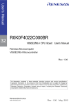
Table 1.1 lists the Peripheral Functions and Their Applications and Figure 1.1 shows the System Configuration.
Table 1.1 Peripheral Functions and Their Applications
Peripheral Function
Flash memory (on-chip flash memory)
Flash macro service
Asynchronous serial interface J (UARTJ)
Application
Program storage area
Reprogramming flash memory
Reprogramming data/Message communication
V850E2/ML4 CPU board
(Type: R0K0F4022C000BR)
V850E2/ML4
Operate
Flash macro service
Flash memory
Readout
Serial
communication
Host device
Execute flash function
Serial
communication
Program data
Message
FSL*
Serial port
connector
(J5)
UARTJ
RS-232C
transceiver
On-chip RAM
P2_12/RXD0F
P2_13/TXD0F
Reprogram flash
Store receive data
*FSL: Flash Self Programming Library
Figure 1.1 System Configuration
R01AN1475EJ0100 Rev.1.00
Mar. 18, 2013
Page 4 of 63
V850E2/ML4
2.
Updating Program Code Using Flash Self Programming
with Asynchronous Serial Interface J (UARTJ)
Operation Confirmation Conditions
The sample code accompanying this application note has been run and confirmed under the conditions below.
Table 2.1 Operation Confirmation Conditions
Item
MCU used
Operating frequency
Operating voltage
Integrated development
environment
C compiler
Operating mode
Sample code version
Board used
Device used
Contents
V850E2/ML4
Internal system clock (fCLK)
: 200MHz
P bus clock (fPCLK)
: 66.667MHz
Positive power supply for external pins (EVDD) : 3.3V
Positive power supply for internal units (IVDD) : 1.2V
Renesas Electronics Corporation
CubeSuite+ Ver.1.02.01
Renesas Electronics Corporation
CX compiler package Ver.1.21
Compile option
-Cf4022 -oDefaultBuild\v850e2ml4_flash_update_uartj.lmf
-Xobj_path=DefaultBuild -g -Xpro_epi_runtime=off
-IC:\WorkSpace\v850e2ml4_flash_update_uartj\inc
-IC:\WorkSpace\v850e2ml4_flash_update_uartj\FSL -Xdef_var
-Xfar_jump=v850e2ml4_flash_update_uartj.fjp
-Xlink_directive=v850e2ml4_flash_update_uartj.dir
-Xstartup=DefaultBuild\cstart.obj +Xide
-Xmap=DefaultBuild\v850e2ml4_flash_update_uartj.map
-lFSL_T05_REC_R32
-LC:\WorkSpace\v850e2ml4_flash_update_uartj\FSL\lib
-Xrompsec_text=FSL_CODE.text
-Xrompsec_text=FSL_CODE_ROMRAM.text
-Xrompsec_text=FSL_CODE_RAM.text
-Xrompsec_text=FSL_CODE_RAM_USRINT.text
-Xrompsec_text=FSL_CODE_RAM_USR.text
-Xrompsec_text=FSL_CODE_RAM_EX_PROT.text
-Xrompsec_text=INTP1RAM.text -Xrompsec_text=INTTAUA0I0RAM.text
-Xrompsec_text=INTUARTJ0IRRAM.text
-Xhex=DefaultBuild\v850e2ml4_flash_update_uartj.hex
Normal operating mode
(Will be changed to flash memory programming mode at the time of reprogram)
1.00
R0K0F4022C000BR
Serial communication host device
R01AN1475EJ0100 Rev.1.00
Mar. 18, 2013
Page 5 of 63
V850E2/ML4
3.
Updating Program Code Using Flash Self Programming
with Asynchronous Serial Interface J (UARTJ)
Reference Application Notes
For additional information associated with this document, refer to the following application notes.
• V850 Microcontroller Flash Self Programming Library Type05 (R01AN0661EJ)
4.
Peripheral Functions
This chapter provides supplementary information on the flash self programming library which is required to reprogram
the flash memory using the software operated on the V850E2/ML4. Refer to the "V850E2/ML4 User's Manual:
Hardware" and the "V850 Microcontroller Flash Self Programming Library Type05" for basic information.
4.1
Terms for Flash Self Programming
The terms for flash self programming used in this Application note are described as follows.
• Flash macro service
This refers to functions for manipulating the flash memory in devices.
• Flash environment
This refers to the state in which the code flash can be operated by using the flash macro service. There are
special restrictions different from execution of normal programs. A transition to other environment cannot occur
unless the flash environment is ended.
• Flash function
This refers to the individual functions comprising the self-library. They can be used with the C language.
• Internal verification
This refers to the action of internally checking the signal level and verifying that the signal can be read normally
following write to flash memory.
R01AN1475EJ0100 Rev.1.00
Mar. 18, 2013
Page 6 of 63
V850E2/ML4
4.2
Updating Program Code Using Flash Self Programming
with Asynchronous Serial Interface J (UARTJ)
Notes for Flash Self Programming
The V850E2/ML4 has the flash macro service which operates the flash memory. This sample program describes how
to reprogram a program code using the flash self programing library (FSL) which enables to use the flash macro service
with C language. The following notes are provided to use this library.
• The program allocation in RAM executed during the flash environment (including runtime library)
⎯ Setting for a section to allocate the program in RAM
Creation and setting for the link directive file is required to set a section. Refer to "4.2.1 Setting for Link
Directive File" for more details.
⎯ Setting for non-use or allocation in RAM for the functional prologue/epilogue runtime library
This sample program runs the non-use setting of the prologue/epilogue runtime library. Refer to "4.2.2 Setting
for Non-use of Prologue/Epilogue Library" for more details.
⎯ Setting for the exception handler address switching function when using interrupts
The setting for the exception handler address switching function is executed by the software. Refer to "6.7.3
Switching Processing of Exception Handler Address" for more details.
⎯ Initialization of the program area in the RAM allocation destination
When allocating a program to RAM on the V850E2/ML4, the 16-byte boundary area (H'xxxx_xxx0 to
H'xxxx_xxxF) including the program area in the allocation destination is required to be initialized (cleared to
zero). In this sample program, the initialization is executed during the startup routine. Refer to "4.2.5 Setting for
Startup Routine" for its change, and "6.7.1 Startup Routine Processing" for its details.
⎯ Setting for ROMization of the section to expand the program in RAM
Regarding to the setting for ROMizaton on the CubeSuite+, refer to "4.2.3 Setting for ROMization of Section in
RAM".
• The execution of the flash functions are disabled in the interrupt handler
• The far jump specification for the CX compiler when calling function allocated to the address separated more than 2
MB
In this sample program, the far jump option is specified to the function allocated in RAM which is called from
the flash memory. Refer to "4.2.4 Setting for Far Jump Function" for more details.
• Saving, setting and restoring the gp register and the ep register when accessing to the global variables with C
language in the interrupt handler
The above mentioned operations might be required when accessing to the data section in the interrupt handler.
Refer to "4.2.6 Precautions for Interrupts Generated During Use of FSL" for more details.
In regard to the function specification and the system configuration of the FSL, refer to the reference application note,
"V850 Microcontroller Flash Self Programming Library Type05".
In regard to section specification to the CX compiler, allocation address setting, ROMization, and far jump option
specification on the CubeSuite+, refer to "CubeSuite+ V1.03.00 Integrated Development Environment User's manual:
Build (CX compiler)".
In regard to switching the exception handler address, refer to "V850E2 User's Manual: Architecture".
R01AN1475EJ0100 Rev.1.00
Mar. 18, 2013
Page 7 of 63
V850E2/ML4
4.2.1
Updating Program Code Using Flash Self Programming
with Asynchronous Serial Interface J (UARTJ)
Setting for Link Directive File
The link directive file creation and the CubeSuite+ setting are required to change the section assignment. When creating
the link directive file using text editor without the CubeSuite+ menu, the Cube Suite+ setting is required. Drag the link
directive file from explore, and drop it in blank area, the bottom part of the Project Tree. In the CubeSuite+, the file
which has extension of "dir" or "dr" is considered as the link directive file. Select "CX (Build Tool)" under the Project
Tree, and click "Link Options" tab in the Property. Open "Input File" to check "Using link directive file". Refer to
"CubeSuite+ V1.03.00 Integrated Development Environment User's manual: Coding (CX compiler)" for more details.
When creating the link directive file, in this sample program, the reprogram area section (MasterPRG.text), the spare
area section (SparePRG.text), and the FSL area (FSL.CONST) should be created in the flash memory other than the
default area. In addition, the FSL use area and user program area sections (FSL_DATA.bss, FSL_CODE.text,
FSL_CODE_ROMRAM.text, FSL_CODE_RAM.text, FSL_CODE_RAM_USRINT.text,
FSL_CODE_RAM_USR.text, and FSL_CODE_RAM_EX_PROT.text), and exception handler address sections
(INTP1RAM.text, INTTAUA0I0RAM.text, INTFCN0IERRRAM.text, and INTFCN0IRECRAM.text) should be
created in RAM.
In this sample program, the start address of the MasterPRG.text section is assumed to be H'0000 8000. Also the start
address of the exception handler address section is assumed to be the address that adds the respective interrupt handler
address to the transfer destination base address H'FEDF E000
Figure 4.1 shows the Location of Link Directive File.
Figure 4.2 shows the Example of Creation and Section Setting for Link Directive File.
Drag the link directive file which has "dir" or "dr"
for its extension from explore etc. and drop it in
the blank area under the Project Tree to register.
Check here
Figure 4.1 Location of Link Directive File
R01AN1475EJ0100 Rev.1.00
Mar. 18, 2013
Page 8 of 63
V850E2/ML4
Updating Program Code Using Flash Self Programming
with Asynchronous Serial Interface J (UARTJ)
SCONST:!LOAD ?R {
.sconst = $PROGBITS ?A .sconst ;
};
CONST:!LOAD ?R V0x00001100 {
.const = $PROGBITS ?A .const ;
FSL_CONST.const = $PROGBITS ?A FSL_CONST.const ;
# FSL area
Create section for FSL area in ROM
};
TEXT:!LOAD ?RX {
.pro_epi_runtime = $PROGBITS ?AX .pro_epi_runtime ;
.text = $PROGBITS ?AX .text ;
};
# Spare area
SparePRG:!LOAD ?RX V0x00006000 {
SparePRG.text = $PROGBITS ?AX V0x00006000 SparePRG.text ;
Create segment and section for spare area in ROM
};
# Reprogram area
MasterPRG:!LOAD ?RX V0x00008000 {
MasterPRG.text = $PROGBITS ?AX V0x00008000 MasterPRG.text ;
Create segment and section for reprogram area in ROM
};
DATA:!LOAD ?RW V0xfedf0000 {
.data = $PROGBITS ?AW .data ;
.sdata = $PROGBITS ?AWG .sdata ;
.sbss = $NOBITS ?AWG .sbss ;
FSL_DATA.bss = $NOBITS ?AW FSL_DATA.bss ;
.bss = $NOBITS ?AW .bss ;
# FSL use area
Create section for FSL use area in RAM
};
SEDATA:!LOAD ?RW {
.sedata = $PROGBITS ?AW .sedata ;
.sebss = $NOBITS ?AW .sebss ;
};
SIDATA:!LOAD ?RW {
.tidata.byte = $PROGBITS ?AW .tidata.byte ;
.tibss.byte = $NOBITS ?AW .tibss.byte ;
.tidata.word = $PROGBITS ?AW .tidata.word ;
.tibss.word = $NOBITS ?AW .tibss.word ;
.tidata = $PROGBITS ?AW .tidata ;
.tibss = $NOBITS ?AW .tibss ;
.sidata = $PROGBITS ?AW .sidata ;
.sibss = $NOBITS ?AW .sibss ;
};
# Program area allocated to RAM
RAM_PROG:!LOAD ?RX V0xfedfc000 {
FSL_CODE.text = $PROGBITS ?AX FSL_CODE.text ;
FSL_CODE_ROMRAM.text = $PROGBITS ?AX FSL_CODE_ROMRAM.text ;
FSL_CODE_RAM.text = $PROGBITS ?AX FSL_CODE_RAM.text ;
FSL_CODE_RAM_USRINT.text = $PROGBITS ?AX FSL_CODE_RAM_USRINT.text ;
FSL_CODE_RAM_USR.text = $PROGBITS ?AX FSL_CODE_RAM_USR.text ;
FSL_CODE_RAM_EX_PROT.text = $PROGBITS ?AX FSL_CODE_RAM_EX_PROT.text ;
Create segment and section for FSL area
and user program area in RAM
};
# Exception handler area allocated to RAM
INTRAM:!LOAD ?RX V0xfedfe000 L0x00001080 {
INTP1RAM.text = $PROGBITS ?AX V0xfedfe170 H0x0000000a INTP1RAM.text ;
INTTAUA0I0RAM.text = $PROGBITS ?AX V0xfedfe3b0 H0x0000000a INTTAUA0I0RAM.text ;
INTUARTJ0ISRAM.text = $PROGBITS ?AX V0xfedfea50 H0x0000000a INTUARTJ0ISRAM.text ;
INTUARTJ0IRRAM.text = $PROGBITS ?AX V0xfedfea60 H0x0000000a INTUARTJ0IRRAM.text ;
Create segment and section
for exception handler in RAM
};
__tp_TEXT@ %TP_SYMBOL ;
__gp_DATA@ %GP_SYMBOL &__tp_TEXT { DATA
__ep_DATA@ %EP_SYMBOL ;
} ;
Figure 4.2 Example of Creation and Section Setting for Link Directive File
R01AN1475EJ0100 Rev.1.00
Mar. 18, 2013
Page 9 of 63
V850E2/ML4
4.2.2
Updating Program Code Using Flash Self Programming
with Asynchronous Serial Interface J (UARTJ)
Setting for Non-use of Prologue/Epilogue Library
The CubeSuite+ executes setting for non-use of the prologue/epilogue library. Select "CX (Build Tool)" under the
Project Tree, and click "Compile Options" tab in the Property. Select "No (-Xpro_epi_runtime=off)" for "Use
prologue/epilogue library" in "Optimization (Details)".
Figure 4.3 shows the Location of Setting Non-Use of Prologue/Epilogue Library.
Figure 4.3 Location of Setting Non-Use of Prologue/Epilogue Library
R01AN1475EJ0100 Rev.1.00
Mar. 18, 2013
Page 10 of 63
V850E2/ML4
4.2.3
Updating Program Code Using Flash Self Programming
with Asynchronous Serial Interface J (UARTJ)
Setting for ROMization of Section in RAM
The setting for CubeSuite+ is required for ROMization to expand the section in RAM. Select "CX (Built Tool)" under
the Project Tree, and click "ROMize Options" tab in the "Property". From "Text sections included rompsec section",
specify the section required for ROMization out of the sections to be assigned in RAM. Write the section names (one
section per line) in the "Text Edit" window shown by clicking the "..." button on the right.
Figure 4.4 shows the Setting for Romization of Section in RAM.
Figure 4.4 Setting for Romization of Section in RAM
R01AN1475EJ0100 Rev.1.00
Mar. 18, 2013
Page 11 of 63
V850E2/ML4
4.2.4
Updating Program Code Using Flash Self Programming
with Asynchronous Serial Interface J (UARTJ)
Setting for Far Jump Function
In the V850E2/ML4, the end address of the flash memory and the start address of the on-chip RAM are separated more
than 2MB. In the CX compiler, when jumping to the area more than ±2MBs away at the time of function call, the far
jump option should be specified to the call destination function. In this sample code, the far jump option is specified to
the functions called from the ones on the flash memory out of the functions allocated in the on-chip RAM and all
interrupt handlers to be used.
To specify the far jump option, create the file which lists the functions to be specified (far jump calling function list file)
and specify the file name in the compile option "-Xfar_jump". To set in the CubeSuite+, select "CX (Built Tool)" under
the Project Tree, and click "Compile Options" tab in the Property. Click "..." button shown on the right side of "Far
Jump file names" in "Output Code", and write the path of the created far jump calling function list file. (Note that ".fjp"
is recommended for the extension of the far jump calling function list file.)
In the far jump calling function list file, write one function name per line. The function name should have "_
(underscore)" at the beginning of the function name with C language. Note that if "{all_interrupt}" is written, all
interrupt handler functions are subject for the far jump calling functions. For creation of far jump calling function file,
refer to "3.3.3 far jump function" in "CubeSuite+ V1.03.00 Integrated Development Environment User's manual:
Coding (CX compiler)"
Figure 4.5 shows the Location of Far Jump Calling Function File.
Figure 4.6 shows the Example of Creation of Far Jump Calling Function File.
R01AN1475EJ0100 Rev.1.00
Mar. 18, 2013
Page 12 of 63
V850E2/ML4
Updating Program Code Using Flash Self Programming
with Asynchronous Serial Interface J (UARTJ)
Figure 4.5 Location of Far Jump Calling Function File
_uartj0_serial_tx_msg
_flash_reprogram
{all_interrupt}
Far jump option specification is required because the uartj0_serial_tx_msg
function allocated to RAM is also called by the main function in ROM.
Far jump option specification is required because the flash_reprogram
function allocated to RAM is also called by the main function in ROM.
All interrupt handler functions are subject for far jump specification.
The interrupt handler is allocated to RAM, but the far jump option specification is required because
the exception vector table is allocated to ROM with default (before changing base address).
Figure 4.6 Example of Creation of Far Jump Calling Function File
R01AN1475EJ0100 Rev.1.00
Mar. 18, 2013
Page 13 of 63
V850E2/ML4
4.2.5
Updating Program Code Using Flash Self Programming
with Asynchronous Serial Interface J (UARTJ)
Setting for Startup Routine
The stack used in this sample program requires larger area than the stack size (512 bytes) which is set in the standard
startup routine. In the standard startup routine, the function "_rcopy" (ROMize processing) is executed to develop the
data with initial value and the program allocated in RAM. However, when executing the ROMize processing for the
program area, initialize (clear to 0) the 16-byte boundary area of program destination before executing "_rcopy". In this
sample program, the initialization processing for the stack size change and the 16-byte boundary area of program
destination is added for the assembler source file "cstart.asm" in which the standard startup routine is written.
When switching the standard startup routine, create the user-created assembler source file in which the startup routine is
written to register on the CubeSuite+ project. Right click "startup" in "file" under the Project tree, then the menu will
appear to add the startup routine source file.
Figure 4.7 shows the Location of Startup Routine.
Figure 4.8 shows the Example of Startup Routine Preparation (Excerpt from cstart.asm).
Figure 4.7 Location of Startup Routine
R01AN1475EJ0100 Rev.1.00
Mar. 18, 2013
Page 14 of 63
V850E2/ML4
Updating Program Code Using Flash Self Programming
with Asynchronous Serial Interface J (UARTJ)
:
: (Excerpt from cstart.asm)
:
#----------------------------------------------------------------------------#
system stack
#----------------------------------------------------------------------------Change the stack size to the one required for
STACKSIZE
.set
0x500
execution of FSL and user program
.dseg bss
.align 4
__stack:
.ds
(STACKSIZE)
#----------------------------------------------------------------------------#
RESET vector
#----------------------------------------------------------------------------RESET
.cseg
jr
.cseg
.align
__start:
mov32
mov32
add
mov32
mov32
text
__start
text
4
#__tp_TEXT, tp
;
#__gp_DATA, gp
;
tp, gp
;
#__stack+STACKSIZE, sp
#__ep_DATA, ep
;
set tp register
set gp register offset
set gp register
; set sp register
set ep register
mov32
ldsr
#___PROLOG_TABLE, r12
r12, 20
;
; for prologue/epilogue runtime
set CTBP (CALLT base pointer)
jarl
_hdwinit, lp
;
initialize hardware
mov32
mov32
jarl
#__ssbss, r6
#__esbss, r7
__zeroclrw, lp
;
clear sbss section
mov32
mov32
jarl
#__sbss, r6
#__ebss, r7
__zeroclrw, lp
;
clear bss section
mov32
mov32
jarl
0xfedfc000, r6
0xfedfffff, r7
__zeroclrw, lp
;
clear ram_prog section for e2core prefetch processing
Clear the periphery of the area to be used
as a program in RAM to zero before
executing the _rcopy.
:
: (Continued)
:
Figure 4.8 Example of Startup Routine Preparation (Excerpt from cstart.asm)
R01AN1475EJ0100 Rev.1.00
Mar. 18, 2013
Page 15 of 63
V850E2/ML4
4.2.6
Updating Program Code Using Flash Self Programming
with Asynchronous Serial Interface J (UARTJ)
Precautions for Interrupts Generated During Use of FSL
When accessing to the data using the gp register or the ep register in the interrupt processing generated during the use of
the FSL, set appropriate values to the gp register or the ep register before accessing to the data. The saving process for
the gp register or the ep register is required before setting the appropriate values to the registers. Furthermore, the
restoring process for the gp register or the ep register is required before returning from the interrupt processing. If the
said measures are not executed, the data access using the gp register or the ep register cannot be operated properly.
• Sections when accessing to the gp register as a base address:
(The created global variables without section specification will be allocated to .sdata or .sbss.)
⎯ .data
⎯ .bss
⎯ .sdata
⎯ .sbss
• Sections when accessing to the ep register as a base address:
⎯ .sedata
⎯ .sebss
⎯ .sidata
⎯ .sibss
⎯ .tidata.byte
⎯ .tibss.byte
⎯ .tidata.word
⎯ .tibss.word
This sample program does not use a section which accesses to the ep register as a base address and therefore the saving,
setting, and restoring processes for the ep register are not executed in the interrupt processing. The V850E2/ML4 does
not require the saving, setting, and restoring of the gp register when using the FSL.
When changing the microcomputer or using the above sections, the saving, setting, and restoring of the gp register or ep
register may be necessary in the interrupt processing. Cautions are required when applying.
R01AN1475EJ0100 Rev.1.00
Mar. 18, 2013
Page 16 of 63
V850E2/ML4
5.
5.1
Updating Program Code Using Flash Self Programming
with Asynchronous Serial Interface J (UARTJ)
Hardware
Pins Used
Table 5.1 lists the Pins Used and Their Functions.
Table 5.1 Pins Used and Their Functions
Pin Name
P2_12/RXD0F
P2_13/TXD0F
P2_3/INTP1
I/O
Input
Output
Input
R01AN1475EJ0100 Rev.1.00
Mar. 18, 2013
Function
Serial data input
Serial data output
INTP1 interrupt
Page 17 of 63
V850E2/ML4
6.
Updating Program Code Using Flash Self Programming
with Asynchronous Serial Interface J (UARTJ)
Software
6.1
Operation Overview
This sample program receives a program file data for update with Intel expanded hex format using serial
communication, and reprograms the program in the flash memory area. This section describes its operation overview.
6.1.1
Setting for Section Assignment
The access to the flash memory is prohibited while the flash memory is reprogrammed. All programs that are used
during the reprogram of flash memory should be transferred to the area except flash memory. This sample program sets
section assignment to transfer all the sections used during the reprogram to the on-chip RAM.
Table 6.1 lists the Sections Used During Flash Memory Reprogram.
Table 6.1 Sections Used During Flash Memory Reprogram
Section Name
FSL_CODE_ROMRAM.text,
FSL_CODE_RAM.text,
FSL_CODE_RAM_EX_PROT.text
FSL_CODE_RAM_USRINT.text
Program Details
FSL area
Function Name
Flash function
User program interrupt section for
RAM
FSL_CODE_RAM_USR.text
User program section RAM
INTP1RAM.text,
INTTAUA0I0RAM.text,
INTUARTJ0ISRAM.text,
INTUARTJ0IRRAM.text
Jump instruction to interrupt
handler function
uartj0_serial_rx_isr,
flash_store_serial_data, hex2bin,
intp1_isr,
taua0_ch0_interval_timer_isr
uartj0_serial_tx_msg,
flash_reprogram, flash_init,
flash_activate, flash_modecheck,
flash_erase, flash_write,
flash_iverify, flash_end,
flash_set_flmd0
None
This sample program additionally assigns a section area to store a spare program as a solution when the flash memory
reprogram processing failed to reprogram properly such as abort without any intention. For the reprogram area and the
spare area before receiving data (initial state), the programs which have the same processing are stored in respective
area.
Table 6.2 lists the Functions and Sections Specifying Addresses on Flash Memory.
Table 6.2 Functions and Sections Specifying Addresses on Flash Memory
Area
Reprogram area
Spare area
Start Address (block number)
H'0000 8000 (8)
H'0000 6000 (6)
R01AN1475EJ0100 Rev.1.00
Mar. 18, 2013
Store Function Name
taua0_led_sample
taua0_led_spare
ROM Section Name
MasterPRG.text
SparePRG.text
Page 18 of 63
V850E2/ML4
6.1.2
Updating Program Code Using Flash Self Programming
with Asynchronous Serial Interface J (UARTJ)
Overview of Reprogramming Flash Memory
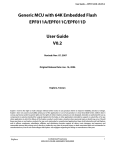
Figure 6.1 shows the Overview of Reprogramming Flash Memory.
Flash memory
H'0000 0000
Exception handler
H'0000 1100
Constants
Functions
ROMized functions allocated to RAM
Execute reprogram
processing using flash
macro service
H'0000 6000
Spare area
H'0000 8000
Reprogram area
H'0000 8FF0
H'0000 8FFF
Checksum area, reprogram area
Transmit to onchip RAM area at
startup
H'000F FFFF
(4)
(1)
On-chip RAM
H'FEDF 0000
(3)
Variables
Buffer 0
Buffer 1
(2)
Binarize serial
communication
receive data
H'FEDF C000
FSL function
Reprogram processing, interrupt
processing etc. for functions
allocated to RAM
Instruction to
reprogram using flash
library
H'FEDF E000
Exception handler
H'FEDF F190
Flash macro service use area
H'FEDF FFFF
Figure 6.1 Overview of Reprogramming Flash Memory
1.
After cancelling the reset, the __S_romp (ROMized section group) is copied to the on-chip RAM during the
cstart.asm processing before starting the main function.
2.
The Intel Extend Hex format data received via serial communication is stored to the on-chip RAM with the state of
binary data which executes writing.
3.
The operation for the flash macro service is executed by the flash library function which is assigned to the on-chip
RAM.
4.
The flash macro service executes the reprogram processing of on-chip flash memory.
R01AN1475EJ0100 Rev.1.00
Mar. 18, 2013
Page 19 of 63
V850E2/ML4
6.1.3
Updating Program Code Using Flash Self Programming
with Asynchronous Serial Interface J (UARTJ)
Process from Startup to Normal Operation
After the system activation, execute initializations in the main processing, and transmit a message "Generate INTP1
interrupt for transition to flash programming event." to the host. Then call the checksum judgment function to judge the
program code in the reprogram area.
The checksum of this sample program uses "Program code size" and "Checksum data" that a program was added to one
byte at a time. The checksum judgment function adds a program one byte at a time with the start address (H'0000 8000)
in the reprogram area for the number of program data size. The calculation result is compared with the checksum
judgment data calculated when received a data (Stored in the last 16-byte area of MasterPRG.text. Refer to 6.1.6 for the
details). The program in the reprogram area will be executed when the calculation result matches the said data, and the
one in the spare area will be executed if there is a difference.
6.1.4
Flash Reprogram Processing after INTP1 Interrupt Input
When the INTP1 interrupt (rising edge detection/ INTP1 switch push down on the board) is generated, moves to flash
reprogram processing.
In the flash reprogram processing, the message "--> INTP1 detected!" is transmitted to the host to erase the reprogram
area. Then the message "Send subroutine code to update program in Intel expanded hex format." is transmitted to the
host to enter wait state for data reception from the host.
In the wait state for data reception, flag variables are used by polling to detect if the flash write is enabled or disabled.
When receiving program file data for update with Intel expanded hex format from the host, the data receive processing
(later described) is executed, and the data is stored into the write data store buffer (write buffer). When the write buffer
becomes full, the buffer data will be written to the flash memory.
This sample program provides a double structured write buffer. Regarding "Storing write data during data receive
processing" and "Writing to the flash memory", each processing should be executed by switching the write buffer to be
used.
6.1.5
Data Receive Processing
After entering in the wait state for data reception, the UARTJ0 receive interrupt is generated every time the serial
communication data is received from the host. When the UARTJ0 interrupt is generated, the received data will be
stored into the serial receive data store buffer (receive buffer) in the order received. When receiving the line feed code,
the data that has been stored in the receive buffer is considered as a record data for one-line. The following data receive
processing is executed to extract write data necessary for updating.
The data receive processing is described as follows referring to Figure 6.2 that shows the Example of Data with Inter
Expanded Hex Format. (The data shown in Figure 6.2 is color coded depending on its function.)
:04000005000013C81C
:020000040000FA
:20800000E0570584CA5EEFFF605F0484E0670583CC6EEFFF606F0483407640FF2E7F054609
:20802000CF86EFFF408E40FF71870546E0970580929E1000609F0480405681FF6A070082E5
:208040002B06FAFF0000406681FF6C5F4082206EFF3F606F00C44076FFFF0E7F66608F86C8
:1A8060000F00408EFFFF518766604096FFFFD2BF6660019A609FC4C57F00C0
:00000001FF
Figure 6.2 Example of Data with Inter Expanded Hex Format
R01AN1475EJ0100 Rev.1.00
Mar. 18, 2013
Page 20 of 63
V850E2/ML4
Updating Program Code Using Flash Self Programming
with Asynchronous Serial Interface J (UARTJ)
• For the processing of each line, determine if the 1st character of the data in the receive buffer shows ":". If it shows
":", judge the 8th and 9th characters (red) as Intel expanded hex format. If the 1st character does not show ":", the
record data become invalid, and returns to wait state for receive data. When the 8th character does not show "0", the
record data also become invalid, and returns to wait state.
• The 8th and 9th characters (red) of the first line show "05". This "05" indicates the start linear address record which
does not have a program data. When received the start linear address record, return to the wait state for receive data
until the next entire record (line data) will be displayed.
• The 8th and 9th characters (red) of the second line show "04". This "04" indicates the extended linear address record
which does not have a program data. When received the extended linear address record, return to the wait state for
receive data until the next entire record will be displayed.
• When the entire 3rd line of the record is displayed, the line is determined as a "data record" because the 8th and 9th
characters (red) show "00". The type of the record can be determined by the numbers from the start to 9th of each
record with Intel expanded hex format.
• The 2th and 3rd characters (blue) of the record indicate the hex for 1-byte of the record size. The four characters
from 4th to 8th (green) indicate the lower 2 bytes of the start data store address of the record.
• Regarding the 10th and later characters (orange) of the record, each two characters indicates 1 byte. In the data
receive processing, the 10th and later characters (orange) is converted into binary data every 2 characters (call "text
binary conversion processing"), store the 1 byte data after the conversion into the write buffer in the order converted.
Add the one byte data for the checksum judgment (checksum data), and count the amounts of the data as a program
code size. When repeated these processing before the last two characters (black) of the record, return to the wait
state for receive data until the next entire record will be displayed.
• When the 8th and 9th (red) characters of the record data show "01", it means "end record" (the bottom line in Figure
6.2). When the end record is shown, terminate the data receive processing without storing receive data. However, if
the data size in the write buffer is less than 16 bytes (unit of flash write) at this point, add H'FF to make the buffer
size 16 bytes.
This sample program provides a double structured write buffer with 16-byte size. Every time the store data in a write
buffer becomes full at 16 bytes, the store destination is switched to another write buffer during the data receive
processing. When the said buffer becomes full, the buffer data is written to the flash memory during flash reprogram
event processing. Writing to the flash memory is executed by polling waiting for receive data, not by an interrupt
processing. When switching the buffer at full, set flag variables which indicate writability.
6.1.6
Processing after Data Deception/Reprogramming
When the end record is determined during data receive processing and the write of flash memory for the receive data is
terminated, the V850E2/ML4 leaves from the wait state for data reception in the flash reprogram event processing, and
writes the data for checksum judgment calculated at the time of data reception (program code size and checksum data/ 2
bytes for each) the flash memory. In this sample program, the data for checksum judgment is stored the last 4 bytes of
the reprogram area H'0000 8FF0 to H'0000 8FF3 (H'0000 8FF0 to H'0000 8FF1 for the program code size and H'0000
8FF2 to H'0000 8FF3 for the checksum data).
After writing the data for checksum judgment, a message is transmitted to the host and the V850E2/ML4 enters wait
state for reset.
R01AN1475EJ0100 Rev.1.00
Mar. 18, 2013
Page 21 of 63
V850E2/ML4
6.1.7
Updating Program Code Using Flash Self Programming
with Asynchronous Serial Interface J (UARTJ)
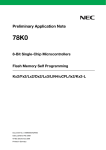
Communication Control Sequence
Figure 6.3 shows the Communication Control Sequence.
V850E2/ML4
Serial communication host
Change exception handler address
Initializations
Checksum judgment
Execute program for reprogram area
or spare area
Generate INTP1 interrupt for
transition to flash programming event.
Transmit message
Output message
Repeat until switch interrupt is generated.
Message processing
Start writing flash memory?
No
Yes
User operation
Push interrupt INTP1
switch SW4
Start reprogramming
after switch interrupt
Transmit message
Output message
--> INTP1 detected!
Message processing
Erase flash
Transmit message
Output message
Send subroutine code to update
program in Intel expanded hex format.
Message processing
Transmit updating program file data
Repeat
Receive data
Write flash memory
Write checksum data
Transmit message
Output message
Successfully Finish Writing Program
Data. Please Reset.
Message processing
Infinite loop for reset wait
User operation
Reset
Figure 6.3 Communication Control Sequence
R01AN1475EJ0100 Rev.1.00
Mar. 18, 2013
Page 22 of 63
V850E2/ML4
6.2
Updating Program Code Using Flash Self Programming
with Asynchronous Serial Interface J (UARTJ)
File Composition
Table 6.3 lists the Files Used in the Sample Code. Files generated by the integrated development environment are not
included in this table.
Table 6.3 Files Used in the Sample Code
File Name
FSL.h
except_handler_ram.asm
Outline
Main processing
INTP1 interrupt processing
Processing related to flash reprogram
Processing related to UARTJ
Sample program for updating,
LED blink port processing
Common header for flash memory
reprogram processing
Fixed length integer type definition
header
FSL header file
Exception handler in RAM*
cstart.asm
Startup routine
main.c
intp1.c
flash.c
uartj0_serial.c
taua0_led_sample.c
flash.h
r_typedefs.h
Remarks
Jump to interrupt processing
function from RAM
Change stack size by
standard startup routine, and
add initialization of program
area in RAM
libFSL_T05_REC_R32.lib
FSL library (32 register mode)
v850e2ml4_flash_update_uartj.dir Link directive setting file
v850e2ml4_flash_update_uartj.fjp Far jump calling functions file
[Note] * Defines the jump instruction from the interrupt handler address to the interrupt handler function to be
allocated on the exception handler.
R01AN1475EJ0100 Rev.1.00
Mar. 18, 2013
Page 23 of 63
V850E2/ML4
6.3
Updating Program Code Using Flash Self Programming
with Asynchronous Serial Interface J (UARTJ)
Constants
Table 6.4 and Table 6.5 list the Constants Used in the Sample Code.
Table 6.4 Constants Used in the Sample Code
Constant Name
Setting Value
RET_OK
RET_ERR
RET_ERR_FLASH_ACTIVATE
RET_ERR_FLASH_MODECHECK
RET_ERR_FLASH_ERASE
RET_ERR_FLASH_WRITE
RET_ERR_FLASH_IVERIFY
RET_ERR_FLASH_DEACTIVATE
RET_ERR_FLASH_FLMD0_HIGH
RET_ERR_FLASH_FLMD0_LOW
RET_ERR_FLASH_HEX_LINESIZE
RET_ERR_FLASH_HEX_DATA
BLOCK_MASTER_PRG
TOP_ADDR_MASTER_PRG
SIZE_MASTER_PRG
SIZE_WRITE
0
-1
-1
-2
-3
-4
-5
-6
-7
-8
-9
-10
8
H'00008000
H'1000
16
TOP_ADDR_MASTER_PRG_CHKSUM
TOP_ADDR_MASTER
_PRG
+ SIZE_MASTER_PRG
- SIZE_WRITE
TOP_ADDR_EXT_HANDLER
H'FEDF E000
R01AN1475EJ0100 Rev.1.00
Mar. 18, 2013
Contents
Normal end
Error end
Failure to start flash environment
Failure to check FLMD0 pin
Failure of erase processing
Failure to write
Failure of internal verification
Failure to terminate flash environment
Failure to set High level for FLMD0 pin
Failure to set Low level for FLMD0 pin
Abnormal numbers of hex file line data
Abnormal hex file program data
Block number of reprogram area
Start address of reprogram area
Reprogram area size (4KB)
Write specification size
Start address of checksum area
(H'00008FF0)
Start address of exception handler
address for transfer destination
Page 24 of 63
V850E2/ML4
Updating Program Code Using Flash Self Programming
with Asynchronous Serial Interface J (UARTJ)
Table 6.5 Constants Used in the Sample Code
Constant Name
FLASH_STATUS_FLMD0_HIGH
FLASH_STATUS_FSL_ACTIVE
HEXDATA_POS_RECMARK
HEXDATA_POS_BYTE_NUM
HEXDATA_POS_RECTYPE_UPPER
HEXDATA_POS_RECTYPE_LOWER
HEXDATA_POS_CODE_TOP
SIZE_BUF_RX_DATA
Setting
Value
H'01
H'02
0
1
7
8
9
525
PORT_BIT_P1_4
PORT_BIT_P2_3
PORT_BIT_P2_12
PORT_BIT_P2_13
H'0010
H'0008
H'1000
H'2000
R01AN1475EJ0100 Rev.1.00
Mar. 18, 2013
Contents
FLMD0 High setting completion status (valid pull-up)
FSL start status
Record mark position of hex data
Position for the number of bytes of hex data
The upper digit position of hex data record type
The lower digit position of hex data record type
Start position of hex data code
Receive data store buffer size (total of the followings)
Record mark: 1 character
The number of bytes: 2 characters
Location address: 4 characters
Record type: 2 characters
Code: 512 characters (max)
Checksum: 2 characters
Return (\r) + New line (\n): 2 characters
Bit position of port function setting P1_4
Bit position of port function setting P2_3
Bit position of port function setting P2_12
Bit position of port function setting P2_13
Page 25 of 63
V850E2/ML4
6.4
Updating Program Code Using Flash Self Programming
with Asynchronous Serial Interface J (UARTJ)
Variables
Table 6.6 lists the Global Variables.
Table 6.6 Global Variables
Type
uint8_t
Variable Name
g_flag_start_flash_reprog
Contents
Start flag for writing flash memory
fsl_status_t
g_error_fsl_status
Store FSL error
uint32_t
uint8_t
g_addr_write_error
g_flag_w_data_buf0_full
Write error address
Write buffer 0 full flag
uint8_t
g_flag_w_data_buf1_full
Write buffer 1 full flag
uint8_t
g_status_end_record
End record receive flag
uint16_t
g_chksm_size
Program code size for write data
uint16_t
g_chksm_data
Checksum data of write data
uint8_t
g_buf_write_data0
[SIZE_WRITE]
g_cnt_store_buf_w_data0
Write data store buffer 0
Write data store buffer 1
uint32_t
g_buf_write_data1
[SIZE_WRITE]
g_cnt_store_buf_w_data1
uint32_t
g_index_rx_data
Receive data storage location index
uint8_t
Receive data store buffer
int8_t
g_buf_rx_data
[SIZE_BUF_RX_DATA]
g_status_store_error
Error flag
uint8_t
g_flag_flash_status
Flash environment status
char
g_msg_sendcode[]
Program transmit request message
uint32_t
uint8_t
R01AN1475EJ0100 Rev.1.00
Mar. 18, 2013
Data counts of write data store buffer 0
Data counts of write data store buffer 1
Function Used
main,
intp1_isr
main, flash_activate,
flash_modecheck,
flash_erase,
flash_write, flash_iverify
main, flash_write
flash_reprogram,
flash_store_serial_data
flash_reprogram,
flash_store_serial_data
flash_reprogram,
flash_store_serial_data
flash_reprogram,
flash_store_serial_data
flash_reprogram,
flash_store_serial_data
flash_reprogram,
flash_store_serial_data
flash_reprogram,
flash_store_serial_data
flash_reprogram,
flash_store_serial_data
flash_reprogram,
flash_store_serial_data
flash_reprogram,
flash_store_serial_data
flash_store_serial_data
flash_reprogram,
flash_store_serial_data
flash_init,
flash_activate,
flash_end
flash_reprogram
Page 26 of 63
V850E2/ML4
6.5
Updating Program Code Using Flash Self Programming
with Asynchronous Serial Interface J (UARTJ)
Functions
Table 6.7 lists the Functions.
Table 6.7 Functions
Function Name
Outline
main
except_handler_addr_set
check_sum_check
intp1_init
intp1_isr
flash_reprogram
flash_init
flash_activate
flash_modecheck
flash_erase
flash_write
flash_iverify
flash_end
flash_set_flmd0
flash_store_serial_data
hex2bin
taua0_led_sample
Main processing
Switching processing of exception handler base address
Checksum judgment of reprogram area
Initialization of INTP1 interrupt
NTP1 interrupt processing
Flash reprogram processing
Initialization of flash environment
Start processing of flash environment
Checking processing of FLMD0 pin using FSL
Erase processing for specified block
Write processing from specified address
Internal verification of specified block
Termination processing of flash environment
Setting for FLMD0 pin level
Store processing of receive data conversion
Text binary conversion processing
Initialization of TAUA0 for LED blink with fixed cycle
(sample function in reprogram area)
taua0_led_spare
Initialization of TAUA0 for LED blink with fixed cycle
(sample function in spare area)
taua0_i0_interval_timer_isr *
TAUA0 interval timer interrupt processing
uartj0_serial_init
Initialization of UARTJ0
uartj0_serial_port_init
Initialization of UARTJ0 ports
uartj0_serial_tx_msg
UARTJ0 message transmit processing
uartj0_serial_rx_isr
UARTJ0 receive interrupt processing
uartj0_serial_status_isr
UARTJ0 status interrupt processing
[Notes] * To set the store processing for received program data by serial communication above the LED flash
processing, the interrupt handler function taua0_ch0_interval_timer_isr enables multiple interrupts.
TAUA0 interval timer interrupt is set to the lower priority than FCN0 reception completion interrupt.
R01AN1475EJ0100 Rev.1.00
Mar. 18, 2013
Page 27 of 63
V850E2/ML4
6.6
Updating Program Code Using Flash Self Programming
with Asynchronous Serial Interface J (UARTJ)
Function Specifications
The following tables list the sample code function specifications.
main
Outline
Header
Declaration
Description
Arguments
Return Value
Main processing
void main (void)
After initializing the variables, the exception handler address, INTP1 interrupt, and
UARTJ, executes the program allocated in the reprogram area or the spare area
according to the checksum judgment. Enables interrupts and outputs INTP1 interrupt
request message, then execute the flash reprogram processing when INTP1
interrupt is generated. Outputs the reset request message for successful reprogram,
or the error message for failure.
None
None
except_handler_addr_set
Switching processing of exception handler base address
Outline
Header
int32_t except_handler_addr_set (uint32_t base_addr)
Declaration
After setting the value specified by the argument to the SW_BASE register, sets 1 to
Description
SET bit of the SW_CTL register. Then transfers the contents of SW_BASE register to
the exception handler base address register (EH_BASE).
uint32_t base_addr
: Exception handler base address setting value
Arguments
(The lower 12-bit should be 0.)
0 (RET_OK)
: Normal end
Return Value
-1 (RET_ERR) : Argument error (The lower 12-bit is not 0.)
check_sum_check
Outline
Header
Declaration
Description
Arguments
Return Value
Checksum judgment of reprogram area
int32_t check_sum_check (void)
Based on the program code size or checksum data stored in the last 4 bytes (H'0000
8FF0 to H'0000 8FF3) of reprogram area, calculates sum value from the start
address (H'0000 8000) of reprogram area to judge the consistency with the
checksum data.
None
0 (RET_OK)
: Checksum matched
-1 (RET_ERR) : Checksum unmatched
R01AN1475EJ0100 Rev.1.00
Mar. 18, 2013
Page 28 of 63
V850E2/ML4
intp1_init
Outline
Header
Declaration
Description
Arguments
Return Value
intp1_isr
Outline
Header
Declaration
Description
Arguments
Return Value
flash_reprogram
Outline
Header
Declaration
Description
Arguments
Return Value
Updating Program Code Using Flash Self Programming
with Asynchronous Serial Interface J (UARTJ)
Initialization of INTP1 interrupt
void intp1_init (void)
Initializes INTP1 interrupt. After setting P2_3 pin function to INTP1 input, sets the
interrupt request to be detected at the falling edge for input using interrupt controller.
Then sets INTP1 interrupt priority level.
None
None
INTP1 interrupt processing
void intp1_isr (void)
Sets the flag which indicates that INTP1 interrupt has been generated.
None
None
Flash reprogram processing
flash.h
int32_t flash_reprogram (void)
Executes initialization of the flash environment, start processing of the flash
environment, checking processing of FLMD0 pin, and reprogram block erase
processing. Then transmits the program transmit request message and enters into
the loop for program receive wait and flash writing. When the program has been
received to the last, executes the flash reprogram termination processing by writing
the checksum data.
None
0 (RET_OK)
: Normal end
-1 (RET_ERR_FLASH_ACTIVATE)
: Failure to start flash environment
-2 (RET_ERR_FLASH_MODECHECK) : Failure to check FLMD0 pin
-3 (RET_ERR_FLASH_ERASE)
: Failure of erase processing
-4 (RET_ERR_FLASH_WRITE)
: Failure of write processing
-5 (RET_ERR_FLASH_IVERIFY)
: Failure of internal verification
-6 (RET_ERR_FLASH_DEACTIVATE) : Failure to terminate flash environment
-7 (RET_ERR_FLASH_FLMD0_HIGH) : Failure to set FLMD0 pin to High level
-8 (RET_ERR_FLASH_FLMD0_LOW) : Failure to set FLMD0 pin to Low level
-9 (RET_ERR_FLASH_HEX_LINESIZE) : Abnormal numbers of hex file data
-10 (RET_ERR_FLASH_HEX_DATA)
: Abnormal program data of hex file
R01AN1475EJ0100 Rev.1.00
Mar. 18, 2013
Page 29 of 63
V850E2/ML4
flash_init
Outline
Header
Declaration
Description
Arguments
Return Value
flash_activate
Outline
Header
Declaration
Description
Arguments
Return Value
flash_modecheck
Outline
Header
Declaration
Description
Arguments
Return Value
Updating Program Code Using Flash Self Programming
with Asynchronous Serial Interface J (UARTJ)
Initialization of flash environment
int32_t flash_init (void)
After executing FLMD0 pin level setting function and setting FLMD0 pin to High level,
initializes the self library by executing the FSL_Init function. When the
flash_set_flmd0 function becomes an error, the RET_ERR_FLASH_FLMD0_HIGH
will be returned.
None
0 (RET_OK)
: Normal end
-7 (RET_ERR_FLASH_FLMD0_HIGH) : Failure to set FLMD0 pin to High level
Start processing of flash environment
int32_t flash_activate (void)
Starts the flash environment by calling the FSL_FlashEnv_Activate function. In case
of normal end, sets the bit which indicates that the flash environment has been
started to the g_flag_flash_status of the global variable, and then the RET_OK is
returned to terminate. When the FSL_FlashEnv_Activate function returns the value
other than the FSL_OK, the return value will be stored in the g_error_fsl_status of the
global variable. The RET_ERR_FLASH_ACTIVATE is returned to terminate.
None
0 (RET_OK)
: Normal end
-1 (RET_ERR_FLASH_ACTIVATE)
: Failure to start flash environment
Checking processing of FLMD0 pin using FSL
int32_t flash_modecheck (void)
Executes checking of FLMD0 pin by calling the FSL_ModeCheck function. In case of
normal end, the RET_OK will be returned to terminate. When the FSL_ModeCheck
function returns other than the FSL_OK, the return value will be stored in the
g_error_fsl_status of the global variable. The RET_ERR_FLASH_MODECHECK is
returned to terminate.
None
0 (RET_OK)
: Normal end
-2 (RET_ERR_FLASH_MODECHECK) : Failure to check FLMD0 pin
R01AN1475EJ0100 Rev.1.00
Mar. 18, 2013
Page 30 of 63
V850E2/ML4
flash_erase
Outline
Header
Declaration
Description
Arguments
Return Value
flash_write
Outline
Header
Declaration
Description
Arguments
Return Value
flash_iverify
Outline
Header
Declaration
Description
Arguments
Return Value
Updating Program Code Using Flash Self Programming
with Asynchronous Serial Interface J (UARTJ)
Erase processing of specified block
int32_t flash_erase (uint32_t start_block, uint32_t end_block)
Executes the block erase by calling the FSL_Erase function according to the
specified argument. After executing the FSL_Erase function, calls the
FSL_StatusCheck function and waits until the erase processing has been completed.
When the FSL_Erase function or the FSL_StatusCheck function returns the error
value, the return value will be stored in the g_error_fsl_status of the global variable.
The RET_ERR_FLASH_ERASE is returned to terminate.
uint32_t start_block
: Start block number of the range to be erased
uint32_t end_block
: End block number of the range to be erased
0 (RET_OK)
: Normal end
-3 (RET_ERR_FLASH_ERASE) : Failure to erase
Write processing from specified address
int32_t flash_write (uint8_t ∗ src_data_addr, uint32_t dst_write_addr, uint32_t length)
Executes writing to the flash memory by calling the FSL_Write function according to
the specified argument. After executing the FSL_Write function, calls the
FSL_StatusCheck function and waits until the write processing has been completed.
When the FSL_Write function or the FSL_StatusCheck function returns the error
value, the value will be stored in the g_error_fsl_status of the global variable. The
RET_ERR_FLASH_WRITE is returned to terminate.
: Start address of write data (outside the on-chip RAM)
uint8_t ∗ src_data_addr
: Destination address of write data (4-word boundary)
uint32_t dst_write_addr
: Write data length
uint32_t length
(word unit, 4-word boundary, MAX: on-chip ROM size)
0 (RET_OK)
: Normal end
-4 (RET_ERR_FLASH_WRITE) : Failure to write
Internal verification of specified block
int32_t flash_iverify (uint32_t start_block, uint32_t end_block)
Calls the FSL_IVerify function according to the argument to execute the internal
verification of specified block. After executing the FSL_IVerify function, calls the
FSL_StatusCheck function and waits until the internal verification has been
completed. When the FSL_IVerify function or the FSL_StatusCheck function returns
the error value, the return value will be stored in the g_error_fsl_status of global
variable. Returns the RET_ERR_FLASH_IVERIFY to terminate.
uint32_t start_block
: Start block number of the range for verify check
uint32_t end_block
: End block number of the range for verify check
0 (RET_OK)
: Normal end
-5 (RET_ERR_FLASH_IVERIFY)
: Failure of internal verification
R01AN1475EJ0100 Rev.1.00
Mar. 18, 2013
Page 31 of 63
V850E2/ML4
flash_end
Outline
Header
Declaration
Description
Arguments
Return Value
flash_set_flmd0
Outline
Header
Declaration
Description
Arguments
Return Value
Updating Program Code Using Flash Self Programming
with Asynchronous Serial Interface J (UARTJ)
Termination processing of flash environment
int32_t flash_end (void)
After terminating the flash environment by calling the FSL_FlashEnv_Deactivate
function, sets FLMD0 pin to Low level by calling the flash_set_flmd0 function. When
the FSL_FlashEnv_Deactivate returns the error value, the
RET_ERR_FLASH_DEACTIVATE will be returned. When the flash_set_flmd0
function returns the value other than 0, the RET_ERR_FLASH_FLMD0_LOW will be
returned to terminate.
None
0 (RET_OK)
: Normal end
-6 (RET_ERR_FLASH_DEACTIVATE) : Failure to terminate flash environment
-8 (RET_ERR_FLASH_FLMD0_LOW) : Failure to set FLMD0 pin to High level
Setting for FLMD0 pin level
int32_t flash_set_flmd0 (uint8_t level)
Sets FLMD control register to switch FLMD0 pull-up/pull-down control. According to
the reprogram sequence for the protect register, substitutes H'A5 for FLMD protect
command register, and then substitutes the value specified by the argument for
FLMD control register. After substituting the invert value, substitutes the value
specified again by the argument. Checks that the register value has been changed to
terminate.
uint8_t level
: 0x00 : Set FLMD0 pin to Low level
0x01 : Set FLMD0 pin to High level
0 (RET_OK)
: Normal end
-1 (RET_ERR)
: Error in writing operation to FLMDCNT register
flash_store_serial_data
Store processing of receive data conversion
Outline
flash.h
Header
void flash_store_serial_data (uint8_t rx_data)
Declaration
Converts the hex data to binary data every line and stores the converted data in the
Description
buffer. When the hex data for one-line is the data record, converts the data in binary
form and saves it until the buffer becomes full. When the hex data for on-line is the
end record, pads the remaining bytes with H'FF and sets the flag which indicates the
receiving has been completed.
uint8_t rx_data
: Receive hex data
Arguments
None
Return Value
R01AN1475EJ0100 Rev.1.00
Mar. 18, 2013
Page 32 of 63
V850E2/ML4
hex2bin
Outline
Header
Declaration
Description
Arguments
Return Value
taua0_led_sample
Outline
Header
Declaration
Description
Arguments
Return Value
taua0_led_spare
Outline
Header
Declaration
Description
Arguments
Return Value
Updating Program Code Using Flash Self Programming
with Asynchronous Serial Interface J (UARTJ)
Text binary conversion processing
int32_t hex2bin(uint8_t upper, uint8_t lower)
Converts the text data (2 characters) to the binary data with 1 byte.
When the data given to the argument is the text data with "0" to "9" or "A" to "F", it is
considered as the valid data and will be converted to the binary data with "H'0 to
H'F". After shifting the conversion result of the first argument (upper) to left by 4 bits
and implementing the OR with the conversion result of the second argument (lower),
returns it as the binary data with 1 byte.
uint8_t upper
: Text data for the upper 4-bit
uint8_t lower
: Text data for the lower 4-bit
0 to 255
: Binary data with 1 byte
-1 (RET_ERR)
: Input data error
Initialization of TAUA0 for LED blink with fixed cycle
(sample function in reprogram area)
void taua0_led_sample (void)
Sets the port connected to the LEDs to output to blink them. Sets TAUA0 to the
interval timer which generates interrupts with fixed cycle.
None
None
Initialization of TAUA0 for LED blink with fixed cycle
(sample function in spare area)
void taua0_led_spare (void)
Sets the port connected to the LEDs to output to blink them. Sets TAUA0 to the
interval timer which generates interrupts with fixed cycle.
None
None
taua0_i0_interval_timer_isr
TAUA0 interval timer interrupt processing
Outline
Header
void taua0_i0_interval_timer_isr (void)
Declaration
Inverts P1_4 output for LED blink.
Description
None
Arguments
None
Return Value
R01AN1475EJ0100 Rev.1.00
Mar. 18, 2013
Page 33 of 63
V850E2/ML4
uartj0_serial_init
Outline
Header
Declaration
Description
Arguments
Return Value
Updating Program Code Using Flash Self Programming
with Asynchronous Serial Interface J (UARTJ)
Initialization of UARTJ0
flash.h
void uartj0_serial_init (void)
After initializing the ports of UARTJ0, executes initial setting for UARTJ0. Then sets
the interrupt level and enables the interrupts to enable UARTJ0 operation.
None
None
uartj0_serial_port_init
Initialization of UARTJ0 ports
Outline
Header
void uartj0_serial_port_init (void)
Declaration
Initializes the ports to use P2_12 pin for reception and P2_13 for transmission in
Description
serial communication.
None
Arguments
None
Return Value
uartj0_serial_tx_msg
Outline
Header
Declaration
Description
Arguments
Return Value
uartj0_serial_rx_isr
Outline
Header
Declaration
Description
Arguments
Return Value
UARTJ0 message transmit processing
flash.h
void uartj0_serial_rx_isr (void)
Provides serial output of the character string specified by the argument from
UARTJ0.
char * msg
: Transmit message character string
None
UARTJ0 receive interrupt processing
void uartj0_serial_rx_isr (void)
Specifies the received data to the argument and executes program data store
processing (flash_store_serial_data function).
None
None
uartj0_serial_status_isr
UARTJ0 status interrupt processing
Outline
Header
void uartj0_serial_status_isr (void)
Declaration
Clears the status as UARTJ0 interrupt processing.
Description
None
Arguments
None
Return Value
R01AN1475EJ0100 Rev.1.00
Mar. 18, 2013
Page 34 of 63
V850E2/ML4
6.7
6.7.1
Updating Program Code Using Flash Self Programming
with Asynchronous Serial Interface J (UARTJ)
Flowcharts
Startup Routine Processing
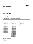
Figure 6.4 shows the Startup Routine Processing.
Startup processing
Initialize pointer registers
Initialize the following criterial pointer registers
when accessing to memories (data and instructions).
tp register
gp register
sp register
ep register
CTBP register
Initialize hardware
hdwinit
Initialize sbss section
_zeroclrw
Initialize bss section
_zeroclrw
Clear program area in RAM
_zeroclrw
Copy ROMized data
_rcopy
Execute main processing
main
Figure 6.4 Startup Routine Processing
R01AN1475EJ0100 Rev.1.00
Mar. 18, 2013
Page 35 of 63
V850E2/ML4
6.7.2
Updating Program Code Using Flash Self Programming
with Asynchronous Serial Interface J (UARTJ)
Main Processing
Figure 6.5 shows the Main Processing.
[Global variable]
int8_t g_flag_start_flash_reprog : Start writing flash memory
main
g_flag_start_flash_reprog ← false
Initialize global variable
Change exception handler address
except_handler_addr_set
Initialize INTP1 interrupt
intp1_init
Initialize UARTJ0
uartj0_serial_init
Checksum judgment
check_sum_check
Checksum error?
Yes
No
Program in reprogram
areaport_led_sample
Program in spare area
port_led_spare
Enable interrupts
__EI
Output message (interrupt switch request)
Transmit message
uartj0_serial_tx_msg
Generate INTP1 interrupt for transition to flash programming event.
Repeat until switch interrupt is generated.
Start writing flash memory?
Yes
Transmit message
uartj0_serial_tx_msg
No
g_flag_start_flash_reprog == false?
Output message (INTP1 interrupt detection)
--> INTP1 detected!
Flash reprogram processing
flash_reprogram
Output message (message corresponds to reprogram result)
Transmit message
uartj0_serial_tx_msg
Return value of flash
reprogram processing?
Messages according to reprogram result;
- Reset request for success
- Message corresponding to an error.
Error
When failed to reprogram, output debug
information.
Transmit message
uartj0_serial_tx_msg
RET_OK
Error code
Write error address
Infinite loop for reset wait
Figure 6.5 Main Processing
R01AN1475EJ0100 Rev.1.00
Mar. 18, 2013
Page 36 of 63
V850E2/ML4
6.7.3
Updating Program Code Using Flash Self Programming
with Asynchronous Serial Interface J (UARTJ)
Switching Processing of Exception Handler Address
Figure 6.6 shows the Switching Processing of Exception Handler Address.
[Argument]
uint32_t base_addr : Setting value of exception handler base address
except_handler_addr_set
Lower 12-bit of
base_addr is 0?
Yes
Switch to EHSW0 bank
Set register bank to H'10
Set transfer value for EH_BASE register
Set SW_BASE register
Transfer
Write 1 into SW_CTL.SET
No
__ldsr(31,H'00000010)
return (RET_ERR)
__ldsr(3,base_addr)
__ldsr(0,H'00000001)
return (RET_OK)
[Note] When switching the exception handler address, the period from the startup of switching procedure to
the termination thereof must be free from exceptions, or any problem in case that an exception was
generated. This sample program has a program that operates properly for any exception handler
address of before/after switching.
If the program cannot be located at the time of application, settings such as interrupt disable will be
required.
Figure 6.6 Switching Processing of Exception Handler Address
R01AN1475EJ0100 Rev.1.00
Mar. 18, 2013
Page 37 of 63
V850E2/ML4
6.7.4
Updating Program Code Using Flash Self Programming
with Asynchronous Serial Interface J (UARTJ)
Checksum Judgment of Reprogram Area
Figure 6.7 shows the Checksum Judgment of Reprogram Area.
check_sum_check
Read checksum judgment data
Ensure that the size does not excceed
4080 bytes (=4K bytes ? 16 bytes)
Write data size falls within
effective range?
Read the following data calculated at the time of last
activation (when data received) and stored in the last
16-byte area of reprogram area;
- Checksum data
- Write data (program code) size
No
Yes
Set start address of reprogram area
Read data (1 byte) in reprogram
area for calculation
No
Complete reading for
write data size?
Yes
Increment read address
of reprogram area
Calculation result matches
with checksum data?
No
Yes
return(RET_OK)
return(RET_ERR)
Figure 6.7 Checksum Judgment of Reprogram Area
R01AN1475EJ0100 Rev.1.00
Mar. 18, 2013
Page 38 of 63
V850E2/ML4
6.7.5
Updating Program Code Using Flash Self Programming
with Asynchronous Serial Interface J (UARTJ)
Initialization of INTP1 Interrupt
Figure 6.8 shows the Initialization of INTP1 Interrupt.
intp1_init
Initialize ports
Port input mode and input buffer in
disabled state
Set port filter
Initialize FCLA15CTL2 register
Initialize PU2 register
Initialize PD2 register
PIBC2 &= ~H'0008
PBDC2 &= ~H'0008
PM2 |= H'0008
PMC2 &= ~H'0008
PIPC2 &= ~H'0008
FCLA15CTL2 ← H'02
PU2 &= ~H'0008
PD2 &= ~H'0008
Set ALT1-IN input of P2_3
(to be used for INTP1 interrupt)
PIS2 |= H'0008
PISE2 &= ~H'0008
PISA2 &= ~H'0008
PFC2 &= ~H'0008
PFCE2 &= ~H'0008
PMC2 |= H'0008
PIBC2 |= H'0008
Enable interrupt level setting
__set_il
__set_il(2, "INTP1")
__set_il(0, "INTP1")
return
Figure 6.8 Initialization of INTP1 Interrupt
R01AN1475EJ0100 Rev.1.00
Mar. 18, 2013
Page 39 of 63
V850E2/ML4
6.7.6
Updating Program Code Using Flash Self Programming
with Asynchronous Serial Interface J (UARTJ)
INPT1 Interrupt Processing
Figure 6.9 shows the INTP1 Interrupt Processing.
[Global variable]
int8_t g_flag_start_flash_reprog: Start reprogramming flash memory
intp1_isr
Set flag to start reprogramming
flash memory
g_flag_start_flash_reprog ← 1
return
[Note] Refer to "4.2.6 Precautions for Interrupts Generated During Use of FSL" for application.
Figure 6.9 INTP1 Interrupt Processing
R01AN1475EJ0100 Rev.1.00
Mar. 18, 2013
Page 40 of 63
V850E2/ML4
6.7.7
Updating Program Code Using Flash Self Programming
with Asynchronous Serial Interface J (UARTJ)
Flash Reprogram Processing
Figure 6.10 and Figure 6.11 show the Flash Reprogram Processing.
flash_reprogram
g_flag_w_data_buf0_full ← false
g_flag_w_data_buf1_full ← false
g_status_data_buff ← 0
g_status_end_record ← 0
Initialize variables
Initialize flash environment
flash_init
No
Yes
ret ← flash_activate()
Start processing for flash environment
flash_activate
Succeed?
Yes
ret ← flash_moecheck()
Check FLMD0 pinflash_modecheck
No
g_index_recv_data ← 0
write_addr ← TOP_ADDR_MASTER_PRG
ret ← flash_init()
Succeed?
No
g_chksm_size ← 0
g_chksm_data ← 0
g_cnt_store_buf_w_data0 ← 0
g_cnt_store_buf_w_data1 ← 0
[Global variables]
uint8_t g_flag_w_data_buf0_full
uint8_t g_flag_w_data_buf1_full
uint8_t g_status_data_buff
uint8_t g_status_end_record;
uint16_t g_chksm_size
uint16_t g_chksm_data
uint8_t g_buf_write_data0[SIZE_WRITE]
uint32_t g_cnt_store_buf_w_data0
uint8_t g_buf_write_data1[SIZE_WRITE]
uint32_t g_cnt_store_buf_w_data1
uint32_t g_index_recv_data;
[Local variable]
fsl_u32 write_addr
: Write buffer 0 full flag
: Write buffer 1 full flag
: Write buffer status
: End record receive flag
: Program code size of write data
: Checksum data of write data
: Write data store buffer 0
: Data counts of write data store buffer 0
: Write data store buffer 1
: Data counts of write data store buffer 1
: Specify receive data storage location
: Write address
Succeed?
Yes
Erase block 8
ret ← flash_erase(BLOCK_MASTER_PRG, BLOCK_MASTER_PRG)
Erase block in reprogram area
flash_erase
No
Succeed?
Yes
Output message
Transmit message
uartj_serial_tx_msg
Send subroutine code to update program in Intel expanded hex format.
A
Failed to write program Succeed
E
D
C
B
g_buf_write_data0[0] ← (g_chksm_size & 0x00ff)
g_buf_write_data0[1] ← ((g_chksm_size & 0xff00) >> 8)
g_buf_write_data0[2] ← (g_chksm_data & 0x00ff)
g_buf_write_data0[3] ← ((g_chksm_data & 0xff00) >> 8)
Create checksum data
ret ← flash_write(g_buf_write_data0, TOP_ADDR_MASTER_PRG_CHKSUM, SIZE_WRITE/4)
Write checksum data
flash_write
No
Succeed?
Yes
ret ← flash_iverify(BLOCK_MASTER_PRG, BLOCK_MASTER_PRG)
Internal verification of reprogram area
flash_iverify
ret_end ← flash_end()
Flash reprogram termination processing
flash_end
ret == RET_OK?
Yes
Return without change when
an error occurs before
termination processing
No
Change return value to error in
termination processing
ret ← ret_end
return(ret)
Figure 6.10 Flash Reprogram Processing (1/2)
R01AN1475EJ0100 Rev.1.00
Mar. 18, 2013
Page 41 of 63
V850E2/ML4
Updating Program Code Using Flash Self Programming
with Asynchronous Serial Interface J (UARTJ)
[Global variables]
uint8_t g_flag_w_data_buf0_full
uint8_t g_flag_w_data_buf1_full
uint8_t g_status_data_buff
uint8_t g_status_end_record;
uint16_t g_chksm_size
uint16_t g_chksm_data
uint8_t g_buf_write_data0[SIZE_WRITE]
uint32_t g_cnt_store_buf_w_data0
uint8_t g_buf_write_data1[SIZE_WRITE]
uint32_t g_cnt_store_buf_w_data1
uint32_t g_index_recv_data;
[Local variable]
fsl_u32 write_addr
A
Error in receive data?
Yes
: Write buffer 0 full flag
: Write buffer 1 full flag
: Write buffer status
: End record receive flag
: Program code size of write data
: Checksum data of write data
: Write data store buffer 0
: Data counts of write data store buffer 0
: Write data store buffer 1
: Data counts of write data store buffer 1
: Specify receive data storage location
: Write address
No
Change return value to error in
termination processing
ret ← g_status_store_error
C
Buffer 0 can be written
into flash memory?
No
Yes
Buffer 1 can be written
into flash memory?
Write buffer 0 into flash memory
flash_write
Update flash write address
ret ← flash_write(g_buf_write_data0,
write_addr,
SIZE_WRITE/4)
Yes
Write buffer 1 into flash memory
flash_write
g_flag_w_data_buf0_full ← false
write_addr += SIZE_WRITE
Update flash write address
Succeed?
Yes
No
No
Succeed?
D
No
Yes
ret ← flash_write(g_buf_write_data1,
write_addr,
SIZE_WRITE/4);
g_flag_w_data_buf0_full ← false
write_addr += SIZE_WRITE
No
E
No data to be written
Receive end record?
Yes
B
Figure 6.11 Flash Reprogram Processing (2/2)
R01AN1475EJ0100 Rev.1.00
Mar. 18, 2013
Page 42 of 63
V850E2/ML4
6.7.8
Updating Program Code Using Flash Self Programming
with Asynchronous Serial Interface J (UARTJ)
Initialization of Flash Environment
Figure 6.12 shows the Initialization of Flash Environment.
[Global variable]
uint8_t g_flag_flash_status : Flash environment status
flash_init
Set FLMD0 pin to High level
flash_set_flmd0
Return value of
flash_set_flmd0 is 0?
Yes
Update flash environment status
No
return(RET_ERR_FLASH_FLMD0_HIGH)
g_flag_flash_status |= FLASH_STATUS_FLMD0_HIGH
Initialize self library
FSL_Init
return(RET_OK)
Figure 6.12 Initialization of Flash Environment
R01AN1475EJ0100 Rev.1.00
Mar. 18, 2013
Page 43 of 63
V850E2/ML4
6.7.9
Updating Program Code Using Flash Self Programming
with Asynchronous Serial Interface J (UARTJ)
Start Processing of Flash Environment
Figure 6.13 shows the Start Processing of Flash Environment.
[Global variables]
uint8_t g_flag_flash_status
fsl_status_t g_error_fsl_status
flash_activate
: Flash environment status
: Store FSL error
Start flash environment
FSL_FlashEnv_Activate
Return value of
FSL_FlashEnv_Activate is
FSL_OK?
No
Yes
Store error state
g_error_fsl_status ← Return value of FSL_FlashEnv_Activate()
return(RET_ERR_FLASH_ACTIVATE)
Update flash environment status
g_flag_flash_status |= FLASH_STATUS_FSL_ACTIVATE
return(RET_OK)
Figure 6.13 Start Processing of Flash Environment
R01AN1475EJ0100 Rev.1.00
Mar. 18, 2013
Page 44 of 63
V850E2/ML4
6.7.10
Updating Program Code Using Flash Self Programming
with Asynchronous Serial Interface J (UARTJ)
Checking Processing of FLMD0 Pin Using FSL
Figure 6.14 shows the Checking Processing of FLMD0 Pin Using FSL.
[Global variable]
fsl_status_t g_error_fsl_status
flash_modecheck
: Store FSL error
Check FLMD0 pin
FSL_ModeCheck
Return value of
FSL_ModeCheck is
FSL_OK?
No
Yes
Store error state
g_error_fsl_status ← Return value of FSL_ModeCheck()
return(RET_ERR_FLASH_MODECHECK)
return(RET_OK)
Figure 6.14 Checking Processing of FLMD0 Pin Using FSL
R01AN1475EJ0100 Rev.1.00
Mar. 18, 2013
Page 45 of 63
V850E2/ML4
6.7.11
Updating Program Code Using Flash Self Programming
with Asynchronous Serial Interface J (UARTJ)
Erase Processing of Specified Block
Figure 6.15 shows the Erase Processing of Specified Block.
[Arguments]
uint32_t start_block
uint32_t end_block
flash_erase
Erase specified block
FSL_Erase
: Start block number of the range to be erased
: End block number of the range to be erased
fsl_status ← Return value of FSL_Erase(start_block, end_block)
Yes
fsl_status == FSL_BUSY?
No
Wait for erase completion
Check previously specified
statusFSL_StatusCheck
fsl_status != FSL_OK?
fsl_status ← Return value of FSL_StatusCheck()
No
Yes
Store error state
g_error_fsl_status ← fsl_status
return(RET_ERR_FLASH_ERASE)
return(RET_OK)
[Global variable]
fsl_status_t g_error_fsl_status
[Local variable]
fsl_status_t fsl_status
: Store FSL error
: Return value of FSL function
Figure 6.15 Erase Processing of Specified Block
R01AN1475EJ0100 Rev.1.00
Mar. 18, 2013
Page 46 of 63
V850E2/ML4
6.7.12
Updating Program Code Using Flash Self Programming
with Asynchronous Serial Interface J (UARTJ)
Write Processing from Specified Address
Figure 6.16 shows the Write Processing from Specified Address.
[Arguments]
uint8_t ∗ src_data_addr
uint32_t dst_write_addr
uint32_t length
flash_write
Write from specified address
FSL_Write
: Write source RAM address
: Write destination flash address
: Write size
fsl_status ← Return value of FSL_Write(src_data_addr, dst_write_addr, length)
Yes
fsl_status == FSL_BUSY?
No
Wait for write completion
Check previously specified
statusFSL_StatusCheck
fsl_status != FSL_OK?
fsl_status ← Return value of FSL_StatusCheck()
No
Yes
Store error state
g_error_fsl_status ← fsl_status
g_addr_write_error ← dst_write_addr
return(RET_ERR_FLASH_WRITE)
return(RET_OK)
[Global variables]
fsl_status_t g_error_fsl_status
uint32_t g_addr_write_error
[Local variable]
fsl_status_t fsl_status
: Store FSL error
: Write error address
: Return value of FSL function
Figure 6.16 Write Processing from Specified Address
R01AN1475EJ0100 Rev.1.00
Mar. 18, 2013
Page 47 of 63
V850E2/ML4
6.7.13
Updating Program Code Using Flash Self Programming
with Asynchronous Serial Interface J (UARTJ)
Internal Verification of Specified Block
Figure 6.17 shows the Internal Verification of Specified Block.
[Arguments]
uint32_t start_block
uint32_t end_block
flash_iverify
Write from specified address
FSL_IVerify
: Start block number of internal verification
: End block number of internal verification
fsl_status ← Return value of FSL_IVerify(start_block, end_block)
Yes
fsl_status == FSL_BUSY?
No
Wait for write completion
Check previously specified
statusFSL_StatusCheck
fsl_status != FSL_OK?
fsl_status ← Return value of
FSL_StatusCheck()
No
Yes
Store error state
g_error_fsl_status ← fsl_status
return(RET_ERR_FLASH_IVERIFY)
return(RET_OK)
[Global variable]
fsl_status_t g_error_fsl_status
[Local variable]
fsl_status_t fsl_status
: Store FSL error
: Return value of FSL function
Figure 6.17 Internal Verification of Specified Block
R01AN1475EJ0100 Rev.1.00
Mar. 18, 2013
Page 48 of 63
V850E2/ML4
6.7.14
Updating Program Code Using Flash Self Programming
with Asynchronous Serial Interface J (UARTJ)
Termination Processing of Flash Environment
Figure 6.18 shows the Termination Processing of Flash Environment.
[Local variable]
int32_t ret
flash_end
ret ← RET_OK
Initialize return value
: Return value
[Global variable]
uint8_t g_flag_flash_status : Flash environment status
Yes (g_flag_flash_status & FLASH_STATUS_FSL_ACTIVATE != 0)
Flash environment
has been started?
No
Terminate flash environment
FSL_FlashEnv_Deactivate
Succeed?
Yes
No
Update flash environment status
g_flag_flash_status &=
~FLASH_STATUS_FSL_ACTIVATE
Set error to return value
ret ← RET_ERR_FLASH_DEACTIVATE
FLMD0 pin has been
set to High?
Yes
(g_flag_flash_status & FLASH_STATUS_FLMD0_HIGH != 0)
No
Set FLMD0 pin to Low level
flash_set_flmd0
Succeed?
No
ret ← flash_set_flmd0(0)
Yes
Update flash environment status
Set error to return value
g_flag_flash_status &=
~FLASH_STATUS_FLMD0_HIGH
ret ← RET_ERR_FLASH_FLMD0_LOW
return(ret)
Figure 6.18 Termination Processing of Flash Environment
R01AN1475EJ0100 Rev.1.00
Mar. 18, 2013
Page 49 of 63
V850E2/ML4
6.7.15
Updating Program Code Using Flash Self Programming
with Asynchronous Serial Interface J (UARTJ)
Setting for FLMD0 Pin Level
Figure 6.19 shows the Setting for FLMD0 Pin Level.
[Argument]
uint8_t level
flash_set_flmd0
Enable writing FLMD protection
command register
Write FLMD control register
Succeed in writing?
: FLMD0 pin level
FLMDPCMD ← H'A5
FLMDCNT ← level
FLMDCNT ← ~level
FLMDCNT ← level
No
((0x00 != FLMDPS) || (level != FLMDCNT)) ?
Yes
return(RET_OK)
return(RET_ERR)
Figure 6.19 Setting for FLMD0 Pin Level
R01AN1475EJ0100 Rev.1.00
Mar. 18, 2013
Page 50 of 63
V850E2/ML4
6.7.16
Updating Program Code Using Flash Self Programming
with Asynchronous Serial Interface J (UARTJ)
Store Processing for Receive Data
Figure 6.20 and Figure 6.21 show the Store Processing for Receive Data.
[Local variable]
uint8_t i
[Global variables]
uint8_t g_buf_recv_data[]
uint32_t g_index_rx_data
: Loop counter
[Argument]
uint8_t rx_data
flash_store_serial_data
: Serial receive data
g_buf_rx_data[g_index_rx_data] ← rx_data
g_index_rx_data ++
Store receive data from the serial
Line feed?
: Receive data store buffer
: Receive data storage location index
No
('\r' != ∗addr_buf) && ('\n' != ∗addr_buf)
Yes
return
Start of line data is ':'?
No
Yes
The upper digit of record is 0?
Yes
No
Restore buffer storage position
to the initial position
g_index_rx_data ← 0
return
Type of records?
0 Data record
1 End record
Unexpected data
2 Extended address record
3 Start address record
4 Extended linear address record
5 Start linear address record
default
Do Nothing
Restore buffer storage position
to the initial position
B
A
Termination Data conversion
Processing store processing
Do Nothing
D
C
g_index_rx_data ← 0
return
Figure 6.20 Store Processing for Receive Data (1/2)
R01AN1475EJ0100 Rev.1.00
Mar. 18, 2013
Page 51 of 63
V850E2/ML4
Updating Program Code Using Flash Self Programming
with Asynchronous Serial Interface J (UARTJ)
A
Obtain data length
by using binary conversion
hex2bin
bin_size ← hex2bin(g_buf_rx_data[HEXDATA_POS_BYTE_NUM],
g_buf_rx_data[HEXDATA_POS_BYTE_NUM+1])
for loop
i = 0; i<bin_size; i++
Obtain data
by using binary conversion
hex2bin
Write buffer is 0?
bin_data ← hex2bin(g_buf_rx_data[HEXDATA_POS_CODE_TOP+2*i],
g_buf_rx_data[HEXDATA_POS_CODE_TOP+2*i+1])
No
Repeat for binary data size
(g_status_data_buff == 0)
Yes
Store in write data store buffer0
Store in write data store buffer 1
g_buf_write_data0[g_cnt_store_buf_w_data0] ← bin_data
g_cnt_store_buf_w_data0++
Buffer 0 is full?
No
No
g_buf_write_data1[g_cnt_store_buf_w_data1] ← bin_data
g_cnt_store_buf_w_data1++
Buffer 1 is full?
Yes
Yes
Change of write buffer 0
Change of write buffer 1
g_cnt_store_buf_w_data0 ← 0
g_flag_w_data_buf0_full ← true
g_status_data_buff ←1
Checksum calculation
g_cnt_store_buf_w_data1 ← 0
g_flag_w_data_buf1_full ← true
g_status_data_buff ← 0
g_chksm_data += bin_data
for loop End
Checksum size calculation
g_chksm_size += bin_size
B
C
Write buffer is 0?
[Local variables]
uint8_t bin_data : Program data
int8_t bin_size : Data size included in a line
uint8_t i
: Loop counter
No
Yes
Pad the remaining of write data store
buffer 0 with H'FF
Pad the remaining of write data store
buffer with H'FF
Change of write buffer 0
Change of write buffer 1
[Global variables]
uint8_t g_buf_rx_data[]
: Receive data store buffer
uint8_t g_buf_write_data0[SIZE_WRITE]
: Write data store buffer 0
uint8_t g_buf_write_data1[SIZE_WRITE]
: Write data store buffer 1
uint8_t g_flag_w_data_buf0_full
: Write buffer 0 full flag
uint8_t g_flag_w_data_buf1_full
: Write buffer 1 full flag
uint32_t g_cnt_store_buf_w_data0
: Data counts of buffer 0
uint32_t g_cnt_store_buf_w_data1
: Data counts of buffer 1
uint8_t g_status_data_buff
: Write buffer status
g_cnt_store_buf_w_data0 ← 0
g_flag_w_data_buf0_full ← true
g_status_data_buff ← 1
g_cnt_store_buf_w_data1 ← 0
g_flag_w_data_buf1_full ← true
g_status_data_buff ← 0
D
Figure 6.21 Store Processing for Receive Data (2/2)
R01AN1475EJ0100 Rev.1.00
Mar. 18, 2013
Page 52 of 63
V850E2/ML4
6.7.17
Updating Program Code Using Flash Self Programming
with Asynchronous Serial Interface J (UARTJ)
Text Binary Conversion Processing
Figure 6.22 shows the Text Binary Conversion Processing.
[Arguments]
uint8_t upper
uint8_t lower
hex2bin
The upper is numeric data?
: Text binary data for the upper 4-bit
: Text binary data for the lower 4-bit
No
The upper indicates '0' to '9' or 'A' to 'F' ?
Yes
Convert the upper into binary data and
store conversion result in the upper
Shift upper to left by 4 bits
The lower is numeric data?
upper <<= 4
No
The lower indicates '0' to '9' or 'A' to 'F' ?
Yes
Convert the lower into binary data and
store conversion result in the lower
return (upper | lower)
return (RET_ERR)
Figure 6.22 Text Binary Conversion Processing
R01AN1475EJ0100 Rev.1.00
Mar. 18, 2013
Page 53 of 63
V850E2/ML4
6.7.18
Updating Program Code Using Flash Self Programming
with Asynchronous Serial Interface J (UARTJ)
TAUA0 Initialization for LED Blink with Fixed Cycle (Sample Function in
Reprogram Area and Spare Area)
Figure 6.23 shows the TAUA0 Initialization for LED blink with Fixed Cycle (Sample Function in Reprogram Area and
Spare Area).
taua0_led_sample,
taua0_led_spare
Set port functions
Output mode setting for LED0 port P1_4
Set TAUA0CMOR0 register
Set TAUA0TPS register
Set TAUA0CDR0 register
Enable interrupt level setting
__set_il
PMC1 &= ~PORT_BIT_P1_4
PM1 &= ~PORT_BIT_P1_4
PDSC1 &= ~PORT_BIT_P1_4
P1 |= PORT_BIT_P1_4
TAUA0CMOR0 ← H'0000
TAUA0CKS bit = B'00
TAUA0STS bit = B'000
TAUA0MD bit = B'0000
: Select operation clock CK0
: Software trigger
: Interval timer mode
Do not output INTTAUA0Im
TAUA0TPS0 ← H'FFF7
TAUA0PRS0 bit = B'0111
: Specify CK0 clock division ratio PCLK/2^7
TAUA0CDR0 ← H'FFFF
: Compare value setting
__set_il(16, "INTTAUA0I0")
__set_il(0, "INTTAUA0I0")
return
Figure 6.23 TAUA0 Initialization for LED blink with Fixed Cycle (Sample Function in Reprogram Area
and Spare Area)
R01AN1475EJ0100 Rev.1.00
Mar. 18, 2013
Page 54 of 63
V850E2/ML4
6.7.19
Updating Program Code Using Flash Self Programming
with Asynchronous Serial Interface J (UARTJ)
TAUA0 Interval Timer Interrupt Processing
Figure 6.24 shows the TAUA0 Interval Timer Interrupt Processing.
taua0_i0_interval_timer_isr
LED port output inversion
P1 ^= PORT_BIT_P1_4
return
[Note] Refer to "4.2.6 Precautions for Interrupts Generated During Use of FSL" for application.
Figure 6.24 TAUA0 Interval Timer Interrupt Processing
R01AN1475EJ0100 Rev.1.00
Mar. 18, 2013
Page 55 of 63
V850E2/ML4
6.7.20
Updating Program Code Using Flash Self Programming
with Asynchronous Serial Interface J (UARTJ)
Initialization of UARTJ0
Figure 6.25 shows the Initialization of UARTJ0.
uartj0_serial_init
Initialize UARTJ0 port
uartj0_serial_port_init
Set UARTJ
Enable interrupt level setting
__set_il
Enable UARTJ0 operation
URTJ0CTL2 ← H'0D90
URTJ0CTL1 ← H'5102
: Baud rate 9600bps
: Data bit length ? 8 bits,
No parity bit,
The number of stop bits ? 1 bit,
LSB first transfer
__set_il(1, "INTUARTJ0IS")
__set_il(0, "INTUARTJ0IS")
__set_il(2, "INTUARTJ0IR")
__set_il(0, "INTUARTJ0IR")
URTJ0CTL0 ← H'E0
return
Figure 6.25 Initialization of UARTJ0
R01AN1475EJ0100 Rev.1.00
Mar. 18, 2013
Page 56 of 63
V850E2/ML4
6.7.21
Updating Program Code Using Flash Self Programming
with Asynchronous Serial Interface J (UARTJ)
Initialization of UARTJ0 Ports
Figure 6.26 shows the Initialization of UARTJ0 Ports.
uartj0_serial_port_init
Initialize ports
Reprogram PDSC2 register
for protection
Set pull-up/pull-down resistors
Set port functions
[Local variable]
uint32_t set_pdsc2
: Setting value for PDSC2 register
PIBC2 &= ~(PORT_BIT_P2_12 | PORT_BIT_P2_13);
PBDC2 &= ~(PORT_BIT_P2_12 | PORT_BIT_P2_13);
PM2 |= (PORT_BIT_P2_12 | PORT_BIT_P2_13);
PMC2 &= ~(PORT_BIT_P2_12 | PORT_BIT_P2_13);
PIPC2 &= ~(PORT_BIT_P2_12 | PORT_BIT_P2_13);
set_pdsc2 ← PDSC2 & ~PORT_BIT_P2_13
PPCMD2 ← H'A5
PDSC2 ← set_pdsc2
PDSC2 ← ~set_pdsc2
PDSC2 ← set_pdsc2
PU2 &= ~PORT_BIT_P2_12
PD2 &= ~PORT_BIT_P2_12
: P2_12 does not connect internal pull-up resistor.
: P2_12 does not connect internal pull-down resistor.
PIS2 |= PORT_BIT_P2_12
PISE2 &= ~PORT_BIT_P2_12
PISA2 &= ~PORT_BIT_P2_12
PFC2 |= (PORT_BIT_P2_12 | PORT_BIT_P2_13)
PFCE2 |= (PORT_BIT_P2_12 | PORT_BIT_P2_13)
PMC2 |= (PORT_BIT_P2_12 | PORT_BIT_P2_13)
PM2 |= PORT_BIT_P2_12
PM2 &= ~PORT_BIT_P2_13
PIBC2 |= PORT_BIT_P2_12
return
Figure 6.26 Initialization of UARTJ0 Ports
R01AN1475EJ0100 Rev.1.00
Mar. 18, 2013
Page 57 of 63
V850E2/ML4
6.7.22
Updating Program Code Using Flash Self Programming
with Asynchronous Serial Interface J (UARTJ)
UARTJ0 Message Transmit Processing
Figure 6.27 shows the UARTJ0 Message Transmit Processing.
uartj0_serial_tx_msg
Initialize processing position
Termination character
of character string?
[Argument]
char ∗ msg
: The number of character strings in character string group
[Local variable]
uint8_t ∗ pt
: Processing position pointer
pt ← msg
No (*pt != '\0')
Yes
URTJ0FTX ← *pt++
Serial output from UARTJ0
Update processing position
Transmission has
been completed?
No
((URTJ0STR0 & 0x01) != 0)
Yes
return
Figure 6.27 UARTJ0 Message Transmit Processing
R01AN1475EJ0100 Rev.1.00
Mar. 18, 2013
Page 58 of 63
V850E2/ML4
6.7.23
Updating Program Code Using Flash Self Programming
with Asynchronous Serial Interface J (UARTJ)
UARTJ0 Receive Interrupt Processing
Figure 6.28 shows the UARTJ0 Receive Interrupt Processing.
uartj0_serial_rx_isr
Read receive data
Program data store processing
flash_store_serial_data
[Local variable]
uint8_t rx_data
: Receive data
rx_data ← URTJ0FRX
flash_store_serial_data(rx_data)
return
[Note] Refer to "4.2.6 Precautions for Interrupts Generated During Use of FSL" for application.
Figure 6.28 UARTJ0 Receive Interrupt Processing
R01AN1475EJ0100 Rev.1.00
Mar. 18, 2013
Page 59 of 63
V850E2/ML4
6.7.24
Updating Program Code Using Flash Self Programming
with Asynchronous Serial Interface J (UARTJ)
UARTJ0 Status Interrupt Processing
Figure 6.29 shows the UARTJ0 Status Interrupt Processing.
[Local variables]
uint8_t reg_urtj0str1
uint8_t reg_urtj0fstr1
uint16_t dummy_read
uint16_t rx_num
uint16_t I
uartj0_serial_status_isr
Read URTJ0STR1 register
Read URTJ0FSTR1 register
Read the number of remaining
receive data in receive FIFO
: Read value of URTJ0STR1
: Read value of URTJ0FSTR1
: Variable to read URTJ0FRX
: The number of remaining receive data in receive FIFO
: Loop counter
reg_urtj0str1 ← URTJ0STR1
reg_urtj0fstr1 ← URTJ0FSTR1
rx_num ← (URTJ0FSTR0 & H'1F00) >> 8
for loop
i = 0; i<rx_num; i++
Read URTJ0FSTR1 register
dummy_read ← URTJ0FRX
Read remaining receive data
in receive FIFO
for loop End
Detect inconsistency of
transmit data and receive data?
Yes
No
Detect receive FIFO overrun?
No
(reg_urtj0str1 & H'04)?
Yes
(reg_urtj0fstr1 & H'20)?
The number of remaining data
in receive FIFO is 0?
No
Receive overrun error processing*
with receive FIFO full
Clear status flag
URTJ0FSTC ← H'02
Clear transmit FIFO pointer
Yes
(rx_num == 0)?
Receive overrun error processing*
with receive FIFO empty
URTJ0STC ← H'1E
URTJ0FSTC ← H'E3
Processing for status
return
[Note] This sample program does not provide the status handling processing. The processing which
corresponds to various statuses should be added according to the user system. Refer to "4.2.6 Precautions
for Interrupts Generated During Use of FSL" when applying this function.
Figure 6.29 UARTJ0 Status Interrupt Processing
R01AN1475EJ0100 Rev.1.00
Mar. 18, 2013
Page 60 of 63
V850E2/ML4
7.
Updating Program Code Using Flash Self Programming
with Asynchronous Serial Interface J (UARTJ)
Operation Overview
In this sample program, the updating program is transmitted by using the serial communication host device. This
chapter describes an example of controlling the data transmission using the PC as a serial communication host device.
Figure 7.1 shows the Hardware Configuration Example for Sample Code.
Serial communication
Application software
V850E2/ML4 CPU board
(Type: R0K0F4022C000BR)
Serial cable
Message
Message
Program data
transfer
Program data
Input file
from menu
V850E2/ML4
This sample code
Host PC
Figure 7.1 Hardware Configuration Example for Sample Code
JP1 for signal selection of the CPU board should be switched to 2-3 to use the INTP1.
The CPU board (serial port connector (J5)) and the host PC should be connected by the serial cable.
Refer to "V850E2/ML4 CPU board R0K0F4022C000BR User's Manual" for more details about the CPU board jumper
settings and connectors.
Table 7.1 Jumper List
Jumper
JP1
1-2 (default)
VBUS
2-3 (used in this program)
P2_3
An operation procedure with the VT100 compatible terminal emulator is described as follows. First of all, activate the
terminal emulator and set for serial port connection. Select the number connected to the board for the serial port number
of the terminal emulator. The setting values for serial ports are listed in Table 7.2.
R01AN1475EJ0100 Rev.1.00
Mar. 18, 2013
Page 61 of 63
V850E2/ML4
Updating Program Code Using Flash Self Programming
with Asynchronous Serial Interface J (UARTJ)
Table 7.2 Serial Port Setting
Item
Bit/sec
Data bit
Parity
Stop bit
Flow control
Setting Value
9600bps
8bit
None
1bit
None
After the above setting is completed, turn on the through board and the board for this sample program.
When the board for this sample program is activated, the V850E2/ML4 transmits a message "Generate INTP1 interrupt
for transition to flash programming event." to the host.
Then the V850E2/ML4 executes the program stored in the reprogram area, and flashes the LEDs on the board with the
fixed period.
When the INTP1 switch (SW4) on the board is pushed in this condition, the V850E2/ML4 transmits a message "-->
INTP1 detected!" to the host. When the INTP1 interrupt is generate, the V850E2/ML4 enters into flash reprogram
processing, and erases the update area. After the erasing is completed, the V850E2/ML4 transmits a message "Send
subroutine code to update program in Intel expanded Hex format." to the host, and enters into wait state for data
reception from the host.
In case of transmitting a file with Intel expanded hex format as a program data from the host, the terminal emulator
transmit function should be used. When choosing and transmitting the said file (such as
v850e2ml4_sample_host_send.hex), in this sample program, the received file is converted to program data and written
to the flash memory.
After the writing is completed, the V850E2/ML4 transmits a message "Successfully Finish Writing Program Data.
Please Reset." to the host, it enters into wait state for reset. Reset the board.
When restarting, the LEDs on the board flash with the different period from previous one. If the data reception/flash
reprogram (update) prior to restart was failed to execute properly, the V850E2/ML4 finds a checksum error at the time
of restarting by reset input. The V850E2/ML4 executes the program in the spare area.
R01AN1475EJ0100 Rev.1.00
Mar. 18, 2013
Page 62 of 63
V850E2/ML4
8.
Updating Program Code Using Flash Self Programming
with Asynchronous Serial Interface J (UARTJ)
Sample Code
Sample code can be downloaded from the Renesas Electronics website.
9.
Reference Documents
User's Manual: Hardware
V850E2/ML4 User's Manual: Hardware Rev.2.00 (R01UH0262EJ)
The latest version can be downloaded from the Renesas Electronics website.
Technical Update/Technical News
The latest information can be downloaded from the Renesas Electronics website.
User's Manual: Development Tools
CubeSuite+ V1.03.00 Integrated Development Environment User's Manual: Coding for CX compiler Rev.1.00
(R20UT2139EJ)
CubeSuite+ V1.03.00 Integrated Development Environment User's Manual: Build for CX compiler Rev.1.00
(R20UT2142EJ)
V850E2/ML4 CPU Board R0K0F4022C000BR User's Manual Rev.1.00 (R20UT0778EJ)
The latest version can be downloaded from the Renesas Electronics website.
User's Manual: Software
V850E2/ML4 User's Manual: Architecture Rev.1.00 (R01US0001EJ)
The latest version can be downloaded from the Renesas Electronics website.
Website and Support
Renesas Electronics website
http://www.renesas.com
Inquiries
http://www.renesas.com/contact/
R01AN1475EJ0100 Rev.1.00
Mar. 18, 2013
Page 63 of 63
REVISION HISTORY
Rev.
Date
1.00
Mar. 18, 2013
V850E2/ML4 Application Note Updating Program Code Using
Flash Self Programming with Asynchronous Serial Interface J
(UARTJ)
Page
—
Description
Summary
First edition issued
All trademarks and registered trademarks are the property of their respective owners.
A-1
General Precautions in the Handling of MPU/MCU Products
The following usage notes are applicable to all MPU/MCU products from Renesas. For detailed usage notes on the
products covered by this document, refer to the relevant sections of the document as well as any technical updates that
have been issued for the products.
1. Handling of Unused Pins
Handle unused pins in accord with the directions given under Handling of Unused Pins in the manual.
⎯ The input pins of CMOS products are generally in the high-impedance state. In operation with an
unused pin in the open-circuit state, extra electromagnetic noise is induced in the vicinity of LSI, an
associated shoot-through current flows internally, and malfunctions occur due to the false
recognition of the pin state as an input signal become possible. Unused pins should be handled as
described under Handling of Unused Pins in the manual.
2. Processing at Power-on
The state of the product is undefined at the moment when power is supplied.
⎯ The states of internal circuits in the LSI are indeterminate and the states of register settings and
pins are undefined at the moment when power is supplied.
In a finished product where the reset signal is applied to the external reset pin, the states of pins
are not guaranteed from the moment when power is supplied until the reset process is completed.
In a similar way, the states of pins in a product that is reset by an on-chip power-on reset function
are not guaranteed from the moment when power is supplied until the power reaches the level at
which resetting has been specified.
3. Prohibition of Access to Reserved Addresses
Access to reserved addresses is prohibited.
⎯ The reserved addresses are provided for the possible future expansion of functions. Do not access
these addresses; the correct operation of LSI is not guaranteed if they are accessed.
4. Clock Signals
After applying a reset, only release the reset line after the operating clock signal has become stable.
When switching the clock signal during program execution, wait until the target clock signal has
stabilized.
⎯ When the clock signal is generated with an external resonator (or from an external oscillator)
during a reset, ensure that the reset line is only released after full stabilization of the clock signal.
Moreover, when switching to a clock signal produced with an external resonator (or by an external
oscillator) while program execution is in progress, wait until the target clock signal is stable.
5. Differences between Products
Before changing from one product to another, i.e. to one with a different part number, confirm that the
change will not lead to problems.
⎯ The characteristics of MPU/MCU in the same group but having different part numbers may differ
because of the differences in internal memory capacity and layout pattern. When changing to
products of different part numbers, implement a system-evaluation test for each of the products.
Notice
1.
Descriptions of circuits, software and other related information in this document are provided only to illustrate the operation of semiconductor products and application examples. You are fully responsible for
the incorporation of these circuits, software, and information in the design of your equipment. Renesas Electronics assumes no responsibility for any losses incurred by you or third parties arising from the
use of these circuits, software, or information.
2.
Renesas Electronics has used reasonable care in preparing the information included in this document, but Renesas Electronics does not warrant that such information is error free. Renesas Electronics
3.
Renesas Electronics does not assume any liability for infringement of patents, copyrights, or other intellectual property rights of third parties by or arising from the use of Renesas Electronics products or
assumes no liability whatsoever for any damages incurred by you resulting from errors in or omissions from the information included herein.
technical information described in this document. No license, express, implied or otherwise, is granted hereby under any patents, copyrights or other intellectual property rights of Renesas Electronics or
others.
4.
You should not alter, modify, copy, or otherwise misappropriate any Renesas Electronics product, whether in whole or in part. Renesas Electronics assumes no responsibility for any losses incurred by you or
5.
Renesas Electronics products are classified according to the following two quality grades: "Standard" and "High Quality". The recommended applications for each Renesas Electronics product depends on
third parties arising from such alteration, modification, copy or otherwise misappropriation of Renesas Electronics product.
the product's quality grade, as indicated below.
"Standard": Computers; office equipment; communications equipment; test and measurement equipment; audio and visual equipment; home electronic appliances; machine tools; personal electronic
equipment; and industrial robots etc.
"High Quality": Transportation equipment (automobiles, trains, ships, etc.); traffic control systems; anti-disaster systems; anti-crime systems; and safety equipment etc.
Renesas Electronics products are neither intended nor authorized for use in products or systems that may pose a direct threat to human life or bodily injury (artificial life support devices or systems, surgical
implantations etc.), or may cause serious property damages (nuclear reactor control systems, military equipment etc.). You must check the quality grade of each Renesas Electronics product before using it
in a particular application. You may not use any Renesas Electronics product for any application for which it is not intended. Renesas Electronics shall not be in any way liable for any damages or losses
incurred by you or third parties arising from the use of any Renesas Electronics product for which the product is not intended by Renesas Electronics.
6.
You should use the Renesas Electronics products described in this document within the range specified by Renesas Electronics, especially with respect to the maximum rating, operating supply voltage
range, movement power voltage range, heat radiation characteristics, installation and other product characteristics. Renesas Electronics shall have no liability for malfunctions or damages arising out of the
use of Renesas Electronics products beyond such specified ranges.
7.
Although Renesas Electronics endeavors to improve the quality and reliability of its products, semiconductor products have specific characteristics such as the occurrence of failure at a certain rate and
malfunctions under certain use conditions. Further, Renesas Electronics products are not subject to radiation resistance design. Please be sure to implement safety measures to guard them against the
possibility of physical injury, and injury or damage caused by fire in the event of the failure of a Renesas Electronics product, such as safety design for hardware and software including but not limited to
redundancy, fire control and malfunction prevention, appropriate treatment for aging degradation or any other appropriate measures. Because the evaluation of microcomputer software alone is very difficult,
please evaluate the safety of the final products or systems manufactured by you.
8.
Please contact a Renesas Electronics sales office for details as to environmental matters such as the environmental compatibility of each Renesas Electronics product. Please use Renesas Electronics
products in compliance with all applicable laws and regulations that regulate the inclusion or use of controlled substances, including without limitation, the EU RoHS Directive. Renesas Electronics assumes
no liability for damages or losses occurring as a result of your noncompliance with applicable laws and regulations.
9.
Renesas Electronics products and technology may not be used for or incorporated into any products or systems whose manufacture, use, or sale is prohibited under any applicable domestic or foreign laws or
regulations. You should not use Renesas Electronics products or technology described in this document for any purpose relating to military applications or use by the military, including but not limited to the
development of weapons of mass destruction. When exporting the Renesas Electronics products or technology described in this document, you should comply with the applicable export control laws and
regulations and follow the procedures required by such laws and regulations.
10. It is the responsibility of the buyer or distributor of Renesas Electronics products, who distributes, disposes of, or otherwise places the product with a third party, to notify such third party in advance of the
contents and conditions set forth in this document, Renesas Electronics assumes no responsibility for any losses incurred by you or third parties as a result of unauthorized use of Renesas Electronics
products.
11. This document may not be reproduced or duplicated in any form, in whole or in part, without prior written consent of Renesas Electronics.
12. Please contact a Renesas Electronics sales office if you have any questions regarding the information contained in this document or Renesas Electronics products, or if you have any other inquiries.
(Note 1)
"Renesas Electronics" as used in this document means Renesas Electronics Corporation and also includes its majority-owned subsidiaries.
(Note 2)
"Renesas Electronics product(s)" means any product developed or manufactured by or for Renesas Electronics.
SALES OFFICES
http://www.renesas.com
Refer to "http://www.renesas.com/" for the latest and detailed information.
Renesas Electronics America Inc.
2880 Scott Boulevard Santa Clara, CA 95050-2554, U.S.A.
Tel: +1-408-588-6000, Fax: +1-408-588-6130
Renesas Electronics Canada Limited
1101 Nicholson Road, Newmarket, Ontario L3Y 9C3, Canada
Tel: +1-905-898-5441, Fax: +1-905-898-3220
Renesas Electronics Europe Limited
Dukes Meadow, Millboard Road, Bourne End, Buckinghamshire, SL8 5FH, U.K
Tel: +44-1628-651-700, Fax: +44-1628-651-804
Renesas Electronics Europe GmbH
Arcadiastrasse 10, 40472 Düsseldorf, Germany
Tel: +49-211-65030, Fax: +49-211-6503-1327
Renesas Electronics (China) Co., Ltd.
7th Floor, Quantum Plaza, No.27 ZhiChunLu Haidian District, Beijing 100083, P.R.China
Tel: +86-10-8235-1155, Fax: +86-10-8235-7679
Renesas Electronics (Shanghai) Co., Ltd.
Unit 204, 205, AZIA Center, No.1233 Lujiazui Ring Rd., Pudong District, Shanghai 200120, China
Tel: +86-21-5877-1818, Fax: +86-21-6887-7858 / -7898
Renesas Electronics Hong Kong Limited
Unit 1601-1613, 16/F., Tower 2, Grand Century Place, 193 Prince Edward Road West, Mongkok, Kowloon, Hong Kong
Tel: +852-2886-9318, Fax: +852 2886-9022/9044
Renesas Electronics Taiwan Co., Ltd.
13F, No. 363, Fu Shing North Road, Taipei, Taiwan
Tel: +886-2-8175-9600, Fax: +886 2-8175-9670
Renesas Electronics Singapore Pte. Ltd.
80 Bendemeer Road, Unit #06-02 Hyflux Innovation Centre Singapore 339949
Tel: +65-6213-0200, Fax: +65-6213-0300
Renesas Electronics Malaysia Sdn.Bhd.
Unit 906, Block B, Menara Amcorp, Amcorp Trade Centre, No. 18, Jln Persiaran Barat, 46050 Petaling Jaya, Selangor Darul Ehsan, Malaysia
Tel: +60-3-7955-9390, Fax: +60-3-7955-9510
Renesas Electronics Korea Co., Ltd.
11F., Samik Lavied' or Bldg., 720-2 Yeoksam-Dong, Kangnam-Ku, Seoul 135-080, Korea
Tel: +82-2-558-3737, Fax: +82-2-558-5141
© 2013 Renesas Electronics Corporation. All rights reserved.
Colophon 2.2