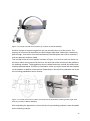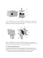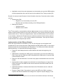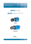
1
MASTER’S THESIS Thesis submitted in partial fulfilment of the requirements for the degree of Master of Science in Engineering at the University of Applied Sciences Technikum Wien Biomedical Engineering Sciences Mouse cursor control with head and eye movements: A low-cost approach by Yat-Sing Yeung, BSc. 1220 Vienna, Viktor-Wittnergasse 33/15 Supervisor 1: Dipl.-Ing. Christoph Veigl Supervisor 2: Dipl.-Ing. (FH) Christoph R. Weiß Vienna, 17.08.2012 Declaration „I confirm that this thesis is entirely my own work. All sources and quotations have been fully acknowledged in the appropriate places with adequate footnotes and citations. Quotations have been properly acknowledged and marked with appropriate punctuation. The works consulted are listed in the bibliography. This paper has not been submitted to another examination panel in the same or a similar form, and has not been published. “ Place, Date Signature Kurzfassung Auf Kopfhalterungen aufgebaute Blickerfassungssysteme können für die Mauszeigersteuerung eines Computersystems verwendet werden. Open-Source Projekte die auf solch einem Ansatz basieren, verlangen vom Benutzer dass der Kopf während der Kalibrierungsprozedur als auch danach so wenig wie möglich bewegt wird, da kleinste Kopfbewegungen die Systemfunktion unerwünscht beeinflussen können. Ein System zur Mauszeigersteuerung wurde entwickelt, das auf einer Kopfhalterung aufbaut und eine Kopfpositionsbestimmung verwendet, um Kopfbewegungen während der Blickerfassung zu kompensieren. Auf der Kopfhalterung befestigt sind eine modifizierte webcam für die Blickerfassung und ein „sensor board“ mit einem optischen Infrarotsensor für die Kopfpositionsbestimmung. Die zweite Hardwarekomponente für die Kopfpositionsbestimmung ist eine Halterung für Infrarot LEDs, das auf einem Computer Bildschirm befestigt werden kann. Der Software Teil des Systems ist in der AsTeRICS Plattform als ein Plug-In integriert. Die AsTeRICS Plattform ist ein momentan in der Entwicklung befindliches Projekt, dass das Ziel hat, Personen mit motorischen Einschränkungen eine flexible Plattform zu schaffen, um unterschiedliche Sensoren und Aktuatoren für deren individuellen Anwendungsfall miteinander zu kombinieren Eine funktionelle Überprüfung des entwickelten Systems wurde durchgeführt und das System für funktionstüchtig befunden, da Kopfbewegungen während der Blickerfassung mit der vorgestellten Methode kompensiert werden können. Schlagwörter: Blickerfassung, Kopfpositionsbestimmung Abstract Head mounted eye tracking systems can be used for controlling a mouse cursor on a computer system. Open-source projects which use such an approach require that the user holds his/her head still during and after a calibration procedure, as even the slightest head movements could affect the system function in an undesirable way. A head mounted system for mouse cursor control was developed, which uses a head tracker to compensate head movements during eye tracking. Attached to the head mount are a modified webcam for eye tracking and a sensor board with an infrared-optical sensor for head tracking. The second hardware component for the head tracking is a frame for infrared LEDs, which can be placed on top of a computer screen. The software part of the system is integrated into the AsTeRICS platform as a plugin. The AsTeRICS platform is a project under development, with the goal to provide people with motoric disabilities a flexible platform to combine various sensors and actuators for their individual application. A functional test was made and the developed system was considered fully functional, as head movements during eye tracking can be compensated with the introduced method. Keywords: eye tracking, head pose estimation 2 Acknowledgements I want to thank my supervisor Dipl.-Ing. Christoph Veigl for his support and the opportunity to work on a great project. Dipl.-Ing. (FH) Christoph R. Weiß for his aid during the sensor board development. The project partners at the Université Pierre et Marie Curie, for their contribution to the eye tracking module and the head mount system. 3 Table of Contents 1 Introduction ............................................................................................................ 6 1.1 2 Aim ......................................................................................................................... 6 State-of-the-art analysis ......................................................................................... 7 2.1 Eye tracking ........................................................................................................... 7 2.1.1 The human eye ...................................................................................................... 7 2.1.2 Search coils and EOG ............................................................................................ 8 2.1.3 Image based eye tracking ...................................................................................... 9 2.1.4 Pupil tracking algorithms ...................................................................................... 12 2.2 2.2.1 Head tracking ....................................................................................................... 14 Image based head tracking .................................................................................. 14 2.3 Commercially available products .......................................................................... 15 2.4 Open source projects and scientific research ....................................................... 17 3 Concept and implementation ................................................................................ 18 3.1 Hardware-platform for head pose estimation ........................................................ 23 3.1.1 IR-LED frame ....................................................................................................... 23 3.1.2 Sensor board hardware ........................................................................................ 24 3.1.3 Sensor board firmware ......................................................................................... 27 3.2 3.2.1 Hardware-platform for eye tracking ....................................................................... 33 IR-camera system ................................................................................................ 33 3.3 Infrared radiation safety aspects ........................................................................... 35 3.4 PC-software ......................................................................................................... 37 3.4.1 Main module ......................................................................................................... 37 3.4.2 Eye tracker module .............................................................................................. 39 3.4.3 Pose estimation module ....................................................................................... 40 3.4.4 Calibration procedure and online program execution ............................................ 41 3.4.5 Eye tracking with head pose estimation ................................................................ 44 3.5 4 Applications .......................................................................................................... 46 Methods and Results ............................................................................................ 50 4.1 Session 1 ............................................................................................................. 54 4.2 Session 2 ............................................................................................................. 56 4 4.3 Session 3 ............................................................................................................. 58 5 Discussion ............................................................................................................ 61 6 Conclusion ........................................................................................................... 64 7 Bibliography ......................................................................................................... 65 List of Figures ...................................................................................................................... 69 List of Tables ....................................................................................................................... 73 List of Abbreviations ............................................................................................................ 74 Appendix.............................................................................................................................. 75 5 1 Introduction Nowadays personal computer systems are playing a huge part in our everyday lives as they are used in areas such as work, education and entertainment. What all these applications have in common is that the use of personal computers is mostly based on the input method via mouse and keyboard. While this is not a problem for a healthy individual, this may be an insurmountable barrier for people with limited freedom of movement of their limbs. In these cases it would be preferable to use input methods which are based on motor abilities of the head region such as head or eye movements. To enable such alternative input methods a system was made which follows a low-cost approach to control a mouse cursor on a computer system. It consists of an eye tracker and a head tracker which are both attached to a head mount. The eye tracker is based on images recorded by a modified webcam to acquire the eye movements. These eye movements are then mapped to a computer screen to position a mouse cursor accordingly. The problem with a stand-alone eye tracker would be the influence of head movements. When an eye tracker is calibrated on a specific head position then it would be accurate for this head position alone. To alleviate this influence a head tracker was used and it is thus an essential part of the developed system. The system is thereby integrated into the Assistive Technology Rapid Integration & Construction Set (AsTeRICS) platform. The AsTeRICS platform makes it possible to combine various assistive technologies while maintaining a consistent interface for easy setup and operation. 1.1 Aim The aim was the design of a low-cost combined eye- and head tracking system for persons with motoric deficiencies of their upper limbs. The system will thereby be used to control a mouse curser. The following parts were to be developed: Sensor board (to collect sensor data of head movements) o Firmware o Circuit board Infrared-LED frame Infrared camera 6 Integration of the sensor board into an existing eye tracking AsTeRICS plugin/component o Processing sensor board data to estimate the head pose o Merging the eye tracking and head pose data 2 State-of-the-art analysis 2.1 Eye tracking 2.1.1 The human eye The nearly spherical eye ball is located in the bony eye socket and embedded into fatty tissue. The most relevant parts of the eye ball for eye tracking are located in the anterior parts of the eye, which hold the optical apparatus to create an image on the retina: Anterior chamber which is filled with an aqueous humour Lens Iris with the central opening (pupil) Transparent cornea Sclera A diagram of the eye is shown in Figure 1. Figure 1: Schematic diagram of the vertebrate eye The iris is a tissue which is located before the lens and it forms an aperture which is called the pupil. Muscular tissue embedded into the iris can increase or decrease the size of the iris und thus also the size of the pupil. The regulation of the pupil diameter is a reflex response and among other stimuli dependent upon the intensity of the incident light. The diameter of the pupil is between 1.5 mm and 8 mm [1]. 7 The colour of the iris is dependent upon the amount and localisation of pigments in the tissue and the posterior (back-sided) pigment epithelium of the iris. Nearly the whole remaining eye ball is covered with the white sclera. An image of the eye is shown in shown in Figure 2. Figure 2: Human eye in visible light [source: Petr Novák, Wikipedia ] 2.1.2 Search coils and EOG For the search coil method, one wire or two wires are processed into a contact lens which can be worn by the user. The wires serve as a coil and the ends of the coil are connected to a voltage-measuring device. To measure the gaze direction, an alternating magnetic field is induced externally, causing a voltage in the coil which is then registered by the measurement device. The eye movements are thus obtained, as the voltage is dependent upon the coil-position in the magnetic field [2] [3]. By using one winding of wire the horizontal as well as the vertical eye movement can be measured (Figure 3a). By using two separate windings of wire (as shown in Figure 3b) the horizontal, vertical as well as the torsional eye movements can be measured. The search coils are cut out in the middle to relieve the sensitive cornea of otherwise existing stress from the contact lens. Figure 3: Search coils: with one winding (a), and 2 windings (b) Electrooculography (EOG) uses the voltage potential difference between the back and the front of the eye to determine the eye position. The potential difference is mainly generated by the “transepithelial potential across retinal pigment epithelium” [4]. They are measured 8 with electrodes applied to the skin area near the eyes and the potential differences between these electrodes are in the range of 15 - 200µV with approximately 20µV changes per degree of eye movement [5] [6]. A drawback of this method is that eyelid movements may affect the measurements heavily [7]. 2.1.3 Image based eye tracking Image acquisition The image based eye tracking uses a camera to record images which can be analysed simultaneously to the recording (on-line) or afterwards (off-line). There are several approaches which can be used exclusively or they can be combined to acquire the eyes position in the recorded images: Visible light limbus tracking (iris tracking) Infrared light glint tracking Infrared light pupil tracking The image acquisition has to prepare the image so that it is suitable for the subsequently used processing approach. The illumination with infrared sources is a commonly used method for the image acquisition as it creates sufficient image brightness in such a way that the user is not irritated by the light source. The images generated with infrared light are similar to a greyscale images with the advantage that the image processing complexity of the next steps is reduced compared to coloured images. This is because greyscale images only have one channel to be processed whereas coloured RGB-images have 3 channels, one for each colour (red, green and blue). Visible light limbus tracking The visible light limbus tracking aims to detect the boundary between the dark iris and the white sclera. This boundary is called limbus and it is relatively easy to detect [8]. Limbus tracking can be suitable for the detection of horizontal eye movements, but the method is inaccurate in its vertical detection of eye movements as the lower and upper part of the limbus are often covered by the eyelids [9]. Infrared light glint tracking The reflections of a light source occurring on the surface of the cornea and the lens are called Purkinje images [6]. Due to the nature of the eye, several reflections occur which are shown in Figure 4. The most distinctive one is the first Purkinje image occurring on the front surface of the cornea. 9 Further Purkinje reflections which are less distinctive occur: on the back surface of the cornea (2nd Purkinje image) on the front surface of the lens (3rd Purkinje image) on the back surface of the lens (4th Purkinje image) Figure 4: Purkinje images (1: first, 2: second, 3: third, 4: fourth Purkinje image) Purkinje images can be used in different ways to acquire the rotational and/or the translational eye movements. Some of the methods which can be used will be described below. Using the first Purkinje image the rotational eye movements can be calculated by taking into account the elliptical curvature of the cornea which is different from the eye ball curvature. In 1867 Helmholtz described that this method is quite accurate but the different curvature of each eye requires that the curvature has to be identified individually which makes this method unsuitable for extensive applications [10]. Nevertheless this method was used in the eye tracking devices EMR-V and EMR-600 from the company NAC according to Joos, et al. [11]. The Dual Purkinje Image (DPI) method as presented in [12] uses the first and the fourth Purkinje image. By doing so it is possible to separate the translational eye movements from the rotational eye movements. Thereby the following properties are utilized: The position of the reflections to each other stays the same during translational movements. Thus they move by the same amount in such a case. With rotational movements the position of these reflections to each other changes. Infrared light pupil tracking 10 This chapter describes the image acquisition methods for pupil tracking whereas algorithms for pupil tracking are described in the next chapter 2.1.4. By illuminating and recording the eye with infrared light the captured image has a more distinctive pupil than in visible light. It appears as either a bright or dark pupil as shown in Figure 5. Figure 5: IR-images from an eye, (A) dark pupil, (B) bright pupil, (C) corneal reflection (source: [13]) A dark pupil appears when the eye is illuminated with a light source which is not in the axis of the camera. The surface of the skin, sclera and iris are illuminated and appear sufficiently bright for the IR-camera. Unlike the surrounding surface the pupil appears dark because IR-light beams coming from the IR-light source is reflected by the retina in approximately the same direction as the origin of the IR-light source. On the contrary, an IR-light source on-axis with the camera will cause the light beams to be reflected from the retina towards the camera. In such a case the pupil will appear bright due to the reflected IR-light (Figure 5). Figure 6: bright and dark pupil method, left: setup for dark pupil method (simplified illustration of a beam path without consideration of refraction), right: setup for bright pupil method 11 The information from Purkinje images / corneal reflections can also be combined with a pupil tracker, thus forming a pupil and corneal reflection tracker. This method can distinguish between translational and rotational eye movements, provided that the illumination source is placed at a fixed location relatively far from the user (e.g. at the corners of a computer screen). The Purkinje images which occur in this case are relatively stable whereas the pupil is not. By analysing the positions of the pupil and the Purkinje image the rotational as well as the translational eye movements can be acquired [6] [14]. 2.1.4 Pupil tracking algorithms Starburst The Starburst algorithm by Li et al. [15] combines a feature based and a model based approach to detect the centre of the pupil with the dark pupil method. Feature based approaches in eye tracking applications have in common that they “detect and localize image features related to the position of the eye” [15]. To detect these feature points the approaches are based upon criteria like thresholds, which can be made available to the user for adjustments. The pupil contour detection of the starburst algorithm is such a feature based approach, which uses a threshold to detect the edge between pupil and iris. The procedure for the detection is as follows: A grayscale image of the eye is generated and a starting point is set inside this image. It can be set anywhere, but to simplify the explanation it is set inside the pupil as shown in Figure 7 (a). From this starting point rays are emanating in all directions. The intensity gradients of the rays are then checked whether they reach the threshold level (Figure 7 (b)). If the limit is reached a feature point is set. Depending on the image quality and the threshold level several feature points can be set to undesirable positions like the limbus or to eyelids. Such undesirable feature points are called outliers. The next step is to extend rays from each previous feature point into the direction of the starting point as shown in Figure 7 (c). From analysing these rays more feature points are set (and again with the possibility of outliers). Now the geometric centre of all feature points is taken as the next starting point and the procedure iterates until the starting point converges, as shown in Figure 7 (d). 12 Figure 7: schematic of the starburst pupil contour detection, (a) setting the start point, (b) rays extended from the start point, (c) rays extended from a feature point back to the start direction, (d) converging points An ellipse is then fitted into the feature points while excluding undesirable outliers by using the Random Sample Consensus (RANSAC) paradigm [16]. “In detail, RANSAC is an iterative procedure that selects many small but random subsets of the data, uses each subset to fit a model, and finds the model that has the most agreement with the data set as a whole” [17]. The starburst algorithm then uses the best fitting parameters from the results of the RANSAC method to optimize the ellipse with a model-based approach. Maximally Stable Extremal Region (MSER) A simplified explanation how the Maximally Stable Extremal Region (MSER) method works is as follows: A binary threshold is applied to an image so that a pixel would be afterwards either black or white. All black pixels are then grouped with their adjacent black pixels so that Extremal Regions are formed for a defined threshold level. Depending on the threshold level, the size and form of such Extremal Regions are varying. The MSER method uses multiple threshold levels and searches for the Extremal Regions which stay maximally stable for these threshold levels. Thus the Maximally Stable Extremal Regions can be found. Example: one MSER in Figure 8 could be the pupil region as it has only slight changes between the threshold levels 5 to 25. 13 Figure 8: Greyscale image and its derivatives with various threshold levels, threshold levels are of 8Bit range [original image: Petr Novák, Wikipedia] As the MSER method can yield multiple MSER regions, an additional processing step is needed to find the region which represents the pupil. To find the pupil region one can limit the search by applying a minimum and maximum size and then search for the region with a shape which fits a circle best. 2.2 Head tracking 2.2.1 Image based head tracking A distinguishing attribute of head trackers are the Degree Of Freedom (DOF) which they are able to detect. The 6 relevant DOF can be assigned into two groups as follows: Translational movements o moving up/down o moving left/right o moving forward/backward Rotational movements o Pitch: tilting forward and backward o Yaw: turning left and right o Roll: tilting side to side One approach for head tracking is the visual face detection with a visible light camera. An image from a person’s head is captured by the camera which is then processed to find distinguishing marks like eyes, ears, nose, mouth, chin, etc. Depending on how these marks are further processed up to 6 DOF can be achieved. The implementation by Baggio [18] uses the acquired distinguishing marks and a 3D-head model from the tracked person to compute the pose by using the POSe estimation with ITeration algorithm (POSIT) [19]. A disadvantage for implementations like Baggio’s is that 14 a sufficient accuracy is only given when the 3D-head model is generated for each person individually, which can be a time consuming and impractical task. Another approach for head tracking is the use of markers. Such markers can be of an active or passive style. Active style markers are driven by a power source and they are typically realised as IR-LEDs. Passive style markers are used to create an easily traceable spot for the recording device. Such markers can have especially bright colours or a reflective surface, so that the markers appear as bright spots when illuminated. The achievable DOFs depend on the amount of markers used, whereby 3 markers would be sufficient for a 6-DOF head tracker. Such a marker based method is used by the software program FreeTrack [20]. 2.3 Commercially available products Chronos Vision: C-ETD The Chronos Eye Tracking Device (C-ETD) is a head mounted eye tracker which was in the first place developed for the usage at the International Space Station (ISS). Figure 9 shows a cosmonaut using the C-ETD which consists of hot mirrors, a bar with attached IRLEDs (below the hot mirrors), laterally positioned IR-cameras, a face mask and an inertial tracking system (above the hot mirrors). The hot mirrors let visible light pass through but they reflect infrared light so that the laterally positioned infrared cameras can record the eye region. A face mask can be used with the C-ETD to reduce slippage to improve tracking stability. The facemask can be fitted to each user individually as the material becomes flexible at temperatures above 65° - 70° Celsius. The 6 DOF inertial tracking system consists of two sensors which measure acceleration and rotation [21]. Figure 9: C-ETD used by a cosmonaut on the ISS (NASA/courtesy of nasaimages.org) 15 Data from the camera and the sensors is recorded by a personal computer (PC) for online and/or offline data processing. The system has a resolution of <0.05° and it costs 17000 US-Dollars [22]. EyeTech Digital Systems: TM4 The stationary black cuboid eye tracker TM4 from the company EyeTech Digital Systems has the dimension of 28 x 4 x 4.5 cm. Adapters are available to mount the device below a computer screen or to position it on a laptop between the keyboard and monitor. The TM4 is powered via USB to operate the IR-LEDs and the camera. The power consumption is specified with 2.5 W when one USB connector is used and 4 W when two USB connectors are used. The images from the camera are thereby sent to the PC for processing where the dark pupil method is used to track one or both pupils with up to 30 frames per second. An accuracy of 0.5° is specified for the system [23]. The included software is used to configure and calibrate the system. The setting “working distance” can be set to the range of 50-60 cm or 60-70 cm. To ensure a proper operation the user has to maintain the head within the tracking space and the software can notify the user if he or she leaves this area. The tracking space is specified with 25 x 14 x 35 cm (width x height x depth). The TM4 eye tracker costs approximately 7000 US-Dollars [24] [25]. Tobii: PCEye The PCEye from the Swedish company Tobii is also a stationary cuboid eye tracker which can be mounted below a computer screen. The dimensions of the PCEye are 25 x 5.3 x 5 cm and it is connected to a PC via USB. The differences between the PCEye and the TM4 are that the PCEye needs a separate power supply (110 V or 230 V) and it has an integrated processing unit so that the processing of the images is done on the device itself, thus reducing the processor workload of the PC. The accuracy of the system is estimated with 0.8°. The recommended screen sizes for the PCEye are 15 to 22 inches with an optimal working distance of 50 to 80 cm depending on the screen size. After calibration head movements are allowed in a tracking space with the size of 40 x 30 x 20 cm (width x height x depth) provided that at least one eye is in the field of view of the device. The PCEye conforms to the medical device standard (Class1/Type B) and it costs approximately 7000 US-Dollars [26] [27]. Origin Instruments: Head Mouse Extreme The Head Mouse Extreme from the company Origin Instruments is a marker based head tracker with 2 DOF. Its main component is a 94 x 56x 13 mm USB-device which contains infrared LEDs and an infrared optical sensor. Disposable reflective markers attached to the 16 head of the user can be detected by the infrared optical sensor as dots. Head movements are translated proportionally into mouse pointer movements on the computer. The device can be installed on top of a computer screen, where a “good rule of thumb is to position the HeadMouse so that it is near eye level and looking directly at the dot. This will provide the user with maximum range of motion.” [28]. Mouse clicks can be performed with the following accessory from Origin Instruments: A sip/puff switch mounted on a headset Dwell clicking with the software Dragger Mouse clicks can also be performed by using third party products (e.g. switches). The sip/puff switch costs 295$, the windows software Dragger 95$ and the main component, the Head Mouse Extreme costs 995$. 2.4 Open source projects and scientific research Several open source projects are using OpenCV [5] [29] [30]. It stands for “Open Source Computer Vision” and it is a library with functions for image processing and machine vision. It is written for the programming language C/C++ and the use of the library is free for both academic and commercial use [31]. The development of the library was initiated in 1999 by Intel and the first official release was in 2006 [6]. ITU Gaze Tracker OpenCV is used by the software program ITU Gaze Tracker, developed by a research group at the IT University of Copenhagen with support from the Communication by Gaze Interaction Association (COGAIN)1 [29]. The software allows a flexible hardware setup to acquire images with the dark pupil method. The system can be configured as a head mounted system or as a remote system. Another possibility is to place the system on a frame-like structure as close to the eye as practically possible. The benefit of this setup is that there is no disturbing element on the head of the user. On the other hand this setup is like the head mounted system very susceptible to head movements. The remote system can use the corneal reflections (glints) to improve precision and allow some tolerance for head movements. As the system is much further away from the user, the camera has to fulfil higher requirements: it should have a higher resolution and a lens 1 The COGAIN association “is a network which joins people who share a common goal. The members in the network are researchers, eye tracker developers and people who work directly with users with disabilities in user centers and hospitals” [50]. On their website is also a comprehensive list of eye trackers 17 with sufficient focal length so that the eye appears large enough in the recorded images for a high accuracy. Gaze tracking system by Ohno, et al. As part of a scientific research a gaze tracking system was developed by Ohno, et al. [32] [33]. The setup consists of three cameras: two visible-light cameras positioned on top of a computer screen, one on the left side and one on the right side. The third camera is positioned on the table below the computer screen and it records images in the infrared spectrum. Figure 10: schematic of the gaze tracking system by Ohno, et al. The two cameras on top of the screen are used to locate the eye position in space while the IR-camera is used for gaze tracking. With the information of the eye position in space and the gaze direction emanating from the eye position, it is possible to obtain the corresponding gaze position on the screen (Figure 10). Experimental assessments showed that an increased accuracy of the system is desired and vision based eye position detection could be more robust. Nevertheless the system was considered robust enough to be practical [33]. 3 Concept and implementation AsTeRICS The concept of the eye tracking with head pose estimation system includes that it shall be integrated into the AsTeRICS platform. The AsTeRICS platform is a project currently under development, with the main objective to “develop a support platform that will facilitate and 18 improve communication resources of people with motor disabilities in their upper limbs” [34]. The AsTeRICS platform consists of the AsTeRICS Configuration Suite (ACS) and the AsTeRICS Runtime Environment (ARE). Both the ACS and the ARE have a graphical user interface and they communicate with each other over a TCP/IP connection. Thus the ACS can be installed on the same PC as the ARE, as well as on any PC with a network connection to the ARE. The ACS is used to create models which consist of one or more components. Each component represents a specific function (e.g. a sensor, a mathematical calculation, a bar display etc.). The components of the model can be arranged in such a way that they optimally suit the end-users needs. By receiving the model from the ACS, the ARE can actually start the appropriate components as defined in the model. System design The system design of the eye tracker with head pose estimation is to utilize various hardware and software parts to calculate its output values x and y. These values represent the gaze point of the user on a computer screen. A sketch of the function is shown in Figure 11. There are two hardware platforms: the sensor board and the infrared camera (IR-camera). These platforms send their data over USB to the eye tracker component of the ARE. The sensor board component data will be processed by the head pose estimation module and the data from the IR-camera will be processed by the eye tracking module. The main module then gathers the results from the eye tracking module as well as from the head pose estimation module, and processes them in such a way that the output matches the point on a computer screen where the user looks at. 19 Figure 11: sketch of the eye tracking with head pose estimation system design It should also be possible to use the sensor board on its own without the eye tracking part. For this purpose, the function of the sensor board component is to pass through all sensor readings to the output port of the component (Figure 12). The update rate of the periodic value reports can thereby be configured over the ACS. Figure 12: sketch of the sensor board system design Sensor board The concept of the sensor board was to develop a multi-purpose platform with the main objective of acquiring sensor data for head pose estimation. This sensor board should thereby comply with the Communication Interface Module (CIM) – specification. One important aspect is that “Communication between actuator and sensor components in the 20 ARE and peripheral devices is currently defined to use a serial communication i.e. a COM port or a virtual COM port” [35]. To fulfil these requirements a pressure sensor, an Inertial Measurement Unit (IMU) and an IR-optical sensor were integrated on a sensor board with a microcontroller which supports a virtual serial communication. The pressure sensor is connected to a tube where the user can apply a pressure over a mouth piece. With the appropriate data processing on the software side this pressure sensor can serve as a suck/blow switch. The IMU consists of a gyroscope, an accelerometer and a compass. The idea behind integrating an IMU is that the data provided from these sensors can be used to measure head movements alternatively or in addition to the IR-optical sensor. Readings from the three IMU sensors can thereby be combined with each other in an advantageous way: The gyroscope can measure rotation but it has a drift which can be compensated when readings from the accelerometer and compass are taken into account. The accelerometer can measure translational acceleration and thus acquire where “bottom” is due to the gravitation of the earth. What it cannot do is to acquire rotational movements and horizontal orientation. In such a case readings from the gyroscope and compass can be taken into account. The IMU sensors are intended to be used in applications where less accurate head movement measurements are needed, especially when the eye tracker is not used. In such a case only the sensor board is needed and the head mount would be more compact. For head movement measurements without any potential errors from sensor drift, a marker-based method can be used. It consists of an IR-optical sensor and an IR-LED frame with four IR-LED markers. Head mount For optimal data acquisition a head mount system has to be used, to ensure that all sensor readings are in relation to the actual head position. A concept of the head mount system is shown in Figure 13. Attached to the head mount are: The camera arm on the left side of the image The IR-optical sensor on the forehead area The sensor board on the right side of the image 21 Figure 13: concept of head mount system (by courtesy of Darius Mazeika) Another concept to acquire images from the eye would be the use of hot mirrors. The property of hot mirrors is their ability to reflect infrared light while visible light is allowed to pass through. A hot mirror from the manufacturer Edmund Optics was used to evaluate if such an approach would be viable. The concept of the hot mirror system is shown in Figure 14. In front of each eye there is a hot mirror which can be panned to the front. On each side of the head mount are platforms for attaching cameras. These platforms can be rotated around the vertical axis and moved forwards and backwards. IR-LEDs for illumination of the eye region would also be installed on the platform in addition to the camera. Depending on which side is preferable one of the two mounting possibilities can be chosen. Figure 14: concept of hot mirror system, left: front view (in illustration rendering mode), right: side view (by courtesy of Darius Mazeika) After evaluating the approach to use hot mirrors for eye tracking purposes it was discarded due to following reasons: 22 The cost for hot mirrors are relatively high, thus the low-cost approach for eye tracking would be difficult to achieve The approach is not viable for the use with glasses due to reflections on the surface of the glasses. The optimal angle of the camera and hot mirror is difficult to adjust, especially when the illumination with IR-LEDs has also to be considered. Development of 3D-printable parts Fused deposition modelling (FDM) was used to manufacture casings for the IR-optical sensor, the sensor board and the IR-camera. FDM was also used for the IR-LED frame and the IR-camera mounting system. The computer-aided-designs (CAD) of the models were developed in cooperation with Darius Mazeika, who accomplished the work during his internship at the Université Pierre et Marie Curie (UPMC). The material Acrylonitrile butadiene styrene (ABS) was used for the parts, which were printed on the 3D printer Dimension 768 BST from the company Stratasys. 3.1 Hardware-platform for head pose estimation 3.1.1 IR-LED frame An IR-LED frame is used as a reference point and it can be installed on top of a regular computer monitor. The frame is powered via USB and it consists of four IR-LEDs which are arranged in a non-coplanar way. The spatial configuration of the IR-LEDs is listed in Table 7 in the addendum. Figure 15: left: IR-LED frame, LED positions marked with circles, right: schematic of the IR-LED circuit 23 The specifications of the installed IR-LEDs TSAL 7600 from the manufacturer Vishay Semiconductors are: Peak wavelength: 940 nm Forward current: 100 mA Radiant intensity: 25 mW/sr Angle of half intensity: ±30° Diameter: 5 mm Two 22 Ω resistances were each connected in series to two IR-LEDs. The current draw of the circuit is 153 mA at 5 V. 3.1.2 Sensor board hardware The sensor board is equipped with the microcontroller (µC) AT90USB1286 from the manufacturer Atmel and the following sensors: Accelerometer (ADXL345, Analog Devices) Compass (HMC5883L, Honeywell) Gyroscope (ITG-3200, InvenSense) IR-optical sensor (extracted from a Wii remote) Pressure sensor (MP3V7007GP, Freescale Semiconductor) The µC manages most of the sensors over the inter-integrated circuit (I2C) bus, with the exception of the pressure sensor, which is readout with an analogue-digital converter. Furthermore the sensor board communicates with the ARE over a virtual serial port. The prototype of the sensor board is shown in Figure 16. The schematic and the layout, as shown in Figure 59 and Figure 60 of the addendum, were created with the software EAGLE from the manufacturer CadSoft. Figure 16: Prototype of sensor board, 1: µC, 2: accelerometer, 3: compass, 4: gyroscope, 5: pressure sensor, 6: port for IR-source 24 The µC is configured to run at an internal clock of 8 MHz and it has an integrated USBcontroller. The input voltage of the sensor board is taken from the USB connection which is at approx. 5 V. A voltage regulator converts the USB voltage down to 3.3 V. The USB-unit of the µC is connected to the 5 V power rail. All other components of the sensor board, including the sensors and the remaining modules of the µC are connected to the 3.3 V power rail. Atmel ships the µC with a boot loader which supports the upload of firmware with the program FLIP, which can be downloaded from the Atmel website [36]. Another method to program the µC is to use the JTAG interface on the sensor board. The pin configuration is shown in Figure 17. Figure 17: pin configuration of the JTAG interface, left: schematic, right: layout When using the USB method to program the firmware the following has to be considered: On start-up the µC automatically loads the program On reset, the µC runs the boot loader if the HWB pin is ‘0’ On reset, the µC runs the program if the HWB pin is ‘1’ A start-up is considered the initial process of connecting the sensor board to a power source, i.e. to plug it into a USB port of a PC. A reset can be triggered by pushing the RST button which is located at the lower left corner of the sensor board (Figure 16). The Hardware Boot Enable (̅̅̅̅̅̅̅) pin can be set with a solder jumper or zero-ohm resistor to ground or supply voltage potential (Figure 18). By setting the ̅̅̅̅̅̅̅ pin to ‘1’ the boot loader is disabled and the µC loads the program after reset. To run the boot loader after reset, the ̅̅̅̅̅̅̅ pin has to be pulled low (set to ‘0’). Figure 18: zero-ohm resistor for ̅̅̅̅̅̅̅ pin, left: boot loader disabled, right: boot loader enabled 25 The accelerometer, compass, gyroscope and pressure sensor are mounted on the sensor board itself while the IR-optical sensor can be installed externally. It is attached to the sensor board through a pin-connector (Nr. 6 in Figure 16). The IR-optical sensor is able to detect up to four IR-sources. It is basically a video camera with a Multi-Object Tracking engine [37]. The outputs of the IR-optical sensor are twodimensional coordinates of the detected sources, which can be readout over the I2C bus. An external circuit with a 25 MHz oscillator was made to allow a flexible positioning of the IR-optical sensor (Figure 19). The schematic and the layout are shown in Figure 61 and Figure 62 of the appendix. 2 Figure 19: external IR-optical sensor circuit with the sensor, an oscillator and a I C connection (from left to right) The IR-optical sensor was acquired by disassembling the Wii remote. It is not possible to acquire the IR-optical sensor, which is manufactured by the company PixArt, on the open market and the company does not offer a public datasheet. But nevertheless enthusiasts were able to identify the sensor’s function by reverse engineering [38]. In chapter 3.1.3 it is described how the IR-optical sensor can be accessed over the I2C bus. The analogue circuit of the sensor board has a dedicated analogue area so that interference, which can be caused by the digital devices, is kept as low as possible. The analogue part is decoupled from the digital part by using a 10 µH conductor and a 100 nF capacitor. In this analogue part the pressure sensor is integrated and an additional analogue sensor can be connected via soldering pads. The sensor board and the IR-optical sensor circuit each have a separate casing as illustrated in Figure 20 and Figure 21. 26 Figure 20: CAD drawing of the box for the IR-optical sensor, a) assembled box, b) exploded view drawing, 1a: screw axis for top cover fixation, 22: top cover, 23: circuit board for IR-optical sensor, 24: bottom part of the box (by courtesy of Darius Mazeika) Figure 21: CAD drawing of the box for the sensor board, a) assembled box, b) exploded view drawing, 1a: screw axis for top cover fixation, 2a: screw axis for sensor board fixation, 28: top cover, 29: sensor board, 30: bottom part of the box (by courtesy of Darius Mazeika) 3.1.3 Sensor board firmware The sensor board can operate in two different modes: the boot loader mode where a firmware can be loaded into the µC, and the application mode for the regular operation as a CIM device. For each mode, a separate Windows driver for the PC is needed: Boot loader mode: driver can be found in the FLIP installation folder 27 Application mode: this mode implements a virtual serial port over the USB-interface and the appropriate driver can be found on the website of the Teensy project [39] Stored in the sensor board firmware is the information how the µC executes various tasks, such as: Operate as a CIM: o Register as a virtual serial port on the PC o Receive and send data according to the CIM specification Manage the sensors: o Initialize sensors o Readout sensor values The I2C bus used for communication with the digital sensors is set to a 100 kHz clock rate and the communication sessions occur with an interval of 4 ms, so that all sensors can be readout within 20 ms. There are 4 digital sensors, where the IMU sensors can be readout in one session, whereas the IR-optical sensor needs two sessions. Each session was set to 4 ms, resulting in for the readout of all sensors. Thus up to 50 sensor measurements can be acquired per second. Implementation of the CIM specification When the sensor board is connected to a PC, the µC will power up and register itself towards the PC as a virtual serial port. Data between the ARE and the CIM (i.e. the sensor board) can then be sent according to the CIM protocol. The CIM protocol states that each packet shall have 11 bytes with the following functions2: Packet ID: does always have the value 0x4054 and marks the beginning of a packet 2 ARE/CIM ID: it identifies the ARE version if the packet is sent from the ARE to the CIM, if sent from the CIM to the ARE it identifies which CIM device it is and its CIM version/revision number. Data size: this field indicates if, and how many bytes are attached at the end of the header. Serial packet number: packets are numbered in an ascending way; a reply of the CIM to a request of the ARE has the same number as the serial number from the request packet. CIM-Feature address: indicates what feature the CIM should execute / what the CIM executed. Request / Reply Code: if the packet is sent by the ARE to the CIM it contains a request code which classifies the message into a specific request category. If the a detailed description of the CIM-protocol can be found in the AsTeRICS developer manual [33] 28 packet is sent from the CIM to the ARE it classifies the message into a specific reply category. IR camera compass gyro accelerometer Header For sensor data transmission, the sensor board is supporting a “periodic value report” mode, where data is sent in a specified interval from the CIM (in this case: the sensor board) to the ARE. The ARE can thereby start and stop this mode by sending the appropriate start / stop commands. Table 1 shows the structure of the periodic value reports: Byte 0 1 2 3 4 5 6 7 8 9 10 11 12 13 14 15 16 17 18 19 20 21 22 23 24 25 26 27 28 29 30 31 32 33 34 35 36 37 Function Packet ID LSB Packet ID MSB ARE/CIM ID LSB ARE/CIM ID MSB Data Size LSB Data Size MSB Serial Packet Number CIM-Feature address LSB CIM-Feature address MSB Request/Reply Code LSB Request/Reply Code MSB accelerometer X LSB accelerometer X MSB accelerometer Y LSB accelerometer Y MSB accelerometer Z LSB accelerometer Z MSB gyro X LSB gyro X MSB gyro Y LSB gyro Y MSB gyro Z LSB gyro Z MSB compass X LSB compass X MSB compass Y LSB compass Y MSB compass Z LSB compass Z MSB IR-optical sensor, point 1 X LSB IR-optical sensor, point 1 X MSB IR-optical sensor, point 1 Y LSB IR-optical sensor, point 1 Y MSB IR-optical sensor, point 2 X LSB IR-optical sensor, point 2 X MSB IR-optical sensor, point 2 Y LSB IR-optical sensor, point 2 Y MSB IR-optical sensor, point 3 X LSB Value (if applicable) 0x4054 0xA201 0x23 sequential with range: 0x80 - 0xFF 0x0002 0x20 0x00 29 ADC 38 39 40 41 42 43 44 IR-optical sensor, point 3 X MSB IR-optical sensor, point 3 Y LSB IR-optical sensor, point 3 Y MSB IR-optical sensor, point 4 X LSB IR-optical sensor, point 4 X MSB IR-optical sensor, point 4 Y LSB IR-optical sensor, point 4 Y MSB 45 pressure sensor Table 1: structure of periodic value reports (LSB: least significant byte, MSB: most significant byte, X, Y, Z: coordinates of sensor values) Readout of IMU and pressure sensor values The accelerometer, gyroscope and compass are accessed via the I2C Bus and they each have separate outputs for the X, Y and Z axis. They are configured as follows: Accelerometer: 10-Bit resolution with a range of ± 2 g Gyroscope: 16-Bit resolution and range of ± 2000 degrees per second Compass: 12-Bit resolution and recommended range of ± 1.3 Ga ( ) The output of the pressure sensor is a voltage between 0 and 3.3 V which represents a pressure range of ± 7 kPa. The µC converts the voltage with the integrated analogue/digital converter (ADC) to a digital value with a resolution of 10-Bit. In the current firmware implementation, the two least significant bits were omitted resulting in 8-Bit resolution effectively. To reduce noise from the digital part of the circuit, the ADC measurement is located in a timeframe between I2C transmissions. Readout of IR-optical sensor values The I2C addresses for the IR-optical sensor are 0xB0 for master transmit mode and 0xB1 for master receive mode. For proper operation the IR-optical sensor needs to be initialised on start-up by setting registers via the I2C interface. The following table lists the register address, its name, the function of the register and value ranges. Register address Name Function Range 0x06 Maxsize Maximum blob size 0x62 – 0xC8 0x08 Gain Smaller values = higher gain 0x1A Gainlimit Must be smaller than gain 0x1B Minsize Minimum blob size 3–5 0x30 Control register set to 1 for configuration, 8 when configuration is done 1, 8 30 0x33 Mode Used to set different output formats Table 2: IR-optical sensor registers 1, 3, 5 3 During initialisation the following sequence was used for the configuration of the IR-optical sensor with the master transmit mode: 1. Select register 0x30, write 0x01 //control register 2. Select register 0x06, write 0x90 //MAXSIZE register 3. Select register 0x08, write 0xC0 //GAIN register 4. Select register 0x1A, write 0x40 //GAINLIMIT register 5. Select register 0x33, write 0x03 //MODE register 6. Select register 0x30, write 0x08 //control register To read out the data from the IR-optical sensor the following sequence was used: 1. Select register 0x37 with master transmit 2. Master receive to fetch 12 Bytes of data (4 points, each 3 Bytes) The fetched output data from the sensor has the following structure which is repeated four times as up to four blobs can be detected. Each set of three bytes are thereby representing one point: Byte Bit 7 Bit 6 Bit 5 Bit 4 Bit 3 0 X [7:0] 1 Y [7:0] 2 Y [9:8] Bit 2 Bit 1 Bit 0 X [9:8] Table 3: IR-optical sensor output structure of one point [40] The initial output value of each coordinate is 1023 as long as no blob is detected. When a blob is detected, the output value X and Y are the coordinates of the blobs detected by the sensor. A blob in the right upper corner from the sensor’s view will have the coordinate (0 | 0). A blob in the lower left corner will have a coordinate close to, but it will not assume the values (1023 | 767), as a blob is assumed to be bigger in size than 1 pixel. The order by which the detected blobs are assigned to the according output point is as follows: The first detected blob will be assigned as point 1, the second detected blob as point 2 and so on. The blob allocation stays the same as long as the sensor is able to detect the blobs. Blob detection fails when the IR-source is too weak, or the IR-source moves out of the sensor’s field of vision. In this case, the point allocation of the remaining detected blobs 3 Blobs are “points and/or regions in the image that differ in properties like brightness or color compared to the surrounding” [44] 31 stays the same and the point coordinate of the now vanished blob assume the values (1023 | 1023). When a new blob is detected, it will be assigned to the point with the lowest available number. This can go on until four blobs are detected and assigned to the according points. Analysis of I2C transmissions To estimate the performance of the I2C bus, measurements of the I2C transmissions were made with an oscilloscope (DSO-X 3024A, Agilent). It was of particular interest whether 50 sets of sensor data can be successfully acquired in one second. Figure 22 shows the oscilloscope measurement and Table 4 lists the time needed for a complete transmission of the corresponding sensor data. Figure 22: Timings of periodic value reports with 20 ms interval (transmission signals on the SDA 2 line of the I C bus, 1: start command for IR-optical sensor, 2: accelerometer, 3: gyroscope, 4: compass, 5: IR-optical sensor, 6: start command for IR-optical sensor of the next measurement cycle) Sensor Accelerometer Gyroscope Compass IR-optical sensor Transmission time [ms] 1.05 1 0.85 1.45 Table 4: transmission times of sensor readouts 32 The IR-optical sensor has the longest transmission time with 1.45 ms, and the remaining time to the next I2C transmission is still 2.55 ms. As there is enough space in between I2C transmissions, periodic value reports with 20 ms interval are safe to use. 3.2 Hardware-platform for eye tracking 3.2.1 IR-camera system The camera system consists of a modified webcam which uses infrared light to illuminate and record the eye region. This IR-camera system should be distinguished from the IRoptical sensor system. The IR-camera system is pointed towards the eye and uses a modified webcam. The IR-optical sensor is pointed towards the IR-LED frame and uses an optical sensor extracted from the Wii remote. A USB webcam as shown in Figure 23 was used for the camera system [41]. With 15 frames per second (fps) it has a resolution of up to 640x480 pixels and with 30 fps the maximum resolution is 320x240 pixels. The camera has 6 built-in visible-light LEDs. The brightness of these LEDs can be adjusted with a potentiometer which is attached to the USB-cable. Figure 23: left: webcam for the camera system with a 6 mm lens from a lens assortment, right: selection of lenses with the original lens of the webcam and lenses with 2.8 mm, 8 mm, 12 mm, 16mm (from left to right) A stable and homogeneous illumination of the eye region is needed to ensure a proficient recording quality. The pre-mounted LEDs of the webcam would illuminate the eye region but they would also cause discomfort especially at the close distance to the eye where the camera would be mounted. Therefore infrared light was used to illuminate and record the eye region. Recording solemnly in the infrared spectrum reduces also possible interferences caused by other lighting sources. 33 The camera was modified for recording in the infrared spectrum. First, the LEDs were changed to IR-LEDs. The original as well as the modified LED configuration of the webcam is shown in Figure 24. In the modified version the 6 visible light LEDs were replaced with 2 IR-LEDs (SFH 487P, Siemens) with a wavelength of 880 nm. The reasons for using 2 instead of the six LED slots were: Wide beam angle of IR-LEDs ensure an evenly distributed illumination of the eye area, therefore 2 LEDs are sufficient Avoiding parallel connection of multiple LEDs: the forward voltage characteristic of each LED is different due to tolerances during manufacturing. An accurate parallel connection is only possible with a careful selection of LEDs which have similar forward voltage characteristics. This issue is negated by using only 2 LEDs where each one has its own series resistor. Figure 24: left: original LED configuration with visible light LEDs, right: modified circuit with IR-LED The maximum total current for the modified circuit would be: ̇ (3.1) and the maximum partial current which flows through each LED would be: ̇ ̇ . (3.2) The focal length of the original lens is unclear, but it appears to be lower than 6 mm. This assumption was made as the original lens was replaced with a lens of 6 mm focal length, and object sizes in images increased afterwards. The lens mount is thereby using the standardized M12 screw thread size. The 6 mm lens was additionally equipped with an IR-pass filter which was made of the unexposed but developed part of a film and attached to the inner side of the lens as shown 34 in Figure 25 (1) and (2). Figure 25 (3) and (4) shows the camera circuit board with LED modification and the camera in its new casing. Figure 25: (1) unexposed, developed film, (2) film used as IR-pass filter attached to the bottom of the 6 mm lens, (3) circuit board of modified webcam in new casing without cover, (4) camera in new casing with cover closed The camera and its casing are attached to the head mount with an adjustable mounting system. The concept of the camera mounting system is shown in Figure 13 and a prototype of the whole system is shown in Figure 30. 3.3 Infrared radiation safety aspects Illuminating the eye with a light source may pose a hazard to the human health. Excessive irradiation with inadequate light intensities can cause thermal damage to various tissues. Such damages can occur immediately after an exposure to high light intensities (e.g. retinal damage), or they can occur delayed in time (e.g. after repeated irradiation: “infrared cataract” of glassblowers). The International Commission on Non-Ionizing Radiation Protection (ICNIRP) published a statement on far infrared radiation exposure [42] with the following exposure limits: for t > 1000 s (3.3) 35 for t > 10 s (3.4) The above formulae (3.3) and (3.4) are valid for the wavelength of 880 nm as used by the IR-LEDs of the camera, with LR being the limit for the cornea and lens, and EIR being the limit for the retina. To check whether the used IR-LEDs exceed those thresholds, the information sheet M 085 from AUVA [43] was used for the following calculations. It was assumed that the distance of the IR-LED to the eye is 5 cm. First the irradiance Ee was calculated for a pupil diameter of 1.5 mm and 8 mm, by calculating the solid angle Ω under which the pupil is irradiated by the IR-LED and then calculating the radiant power P. By dividing the radiant power P with the area of the pupil A, irradiance Ee can be calculated: (3.5) (3.6) (3.7) The radiance Le can now be calculated with the following formula, where Ω is now the solid angle under which the LED can be seen from the eye: (3.8) Table 5 shows values calculated with the above formulae for one IR-LED. The irradiance as well as the radiance levels are far below the exposure limits as stated by the ICNIRP for both dilated and contracted pupil state. This would also be true for two IR-LEDs as even double the Ee and Le values as listed would be below the exposure limits. Based on these calculations it is considered that the hardware setup is safe to use even under prolonged exposure. P 1.5 mm pupil diameter 8 mm pupil diameter 4.45 µW 125.96 µW 2 Ee 2.52 W/m Le 446 W/(m2∙sr) Exposure limits according to ICNIRP 2.51 W/m2 100 W/m2 443 W/(m2∙sr) 100 000 W/(m2∙sr) Table 5: power, irradiance and radiance calculated with 5 cm distance between IR-LED and eye As the radiant intensity Ie scales multiplicatively into the calculations of P, Ee and Le, a simplified estimation of the risks posed by the IR-LED frame can be made by using the conditions from the above calculations. 36 Such conditions are the pupil diameter of 1.5 mm and 8 mm and a distance between IRLED and eye of 5 cm. The IR-LED of the IR-LED frame has a radiant intensity of 25 mW/sr, which is approximately a factor 8 more than the radiant intensity of the IR-LEDs used for the camera. The factor 8 can then be multiplied with Ee and Le for the pupil diameter of 1.5 and 8 mm. The resulting values are: Ee: 20.16 W/m2 for 1.5 mm pupil diameter Ee: 20.08 W/m2 for 8 mm pupil diameter Le: 3568 W/(m2∙sr) for 1.5 mm pupil diameter Le: 3544 W/(m2∙sr) for 8 mm pupil diameter The irradiance and radiance values at 5 cm distance of the eye caused by an IR-LED as used by the IR-LED frame are well below the exposure limit as stated by the ICNIRP. The estimation were made for one IR-LED as the distance between each of them means that only one can be close to an eye. The prolonged use of the IR-LED frame even in the worst case scenario of 5 cm distance from the eye is therefore considered to pose no health issues. 3.4 PC-software The PC-software for eye tracking with head pose estimation is realised within the eye tracker component of the ARE. A secondary product of the development is the sensor board component which uses the same sensor board hardware, with the difference that the sensor values are passed-through to the output port, while the eye tracker component processes the data from the sensor board internally. The following chapters describe the eye tracker component with its modules in detail. Flow charts regarding the program function can be found in the addendum as Figure 63 to Figure 68. 3.4.1 Main module When the eye tracker component is selected within the AsTeRICS Configuration Suite, the main module is the core unit which is called upon model start-up. A diagram of its coordinating function is shown in Figure 26. In general, the programming language for the ARE and its components is Java. To integrate programs written in C++, such as the eye tracker module and the head pose estimation module, the Java Native Interface (JNI) has to be used. The JNI enables the main module, which is written in Java, to call and be called by the C++ modules. To exchange data with the sensor board, a virtual serial port is used. When the sensor board values are needed, a start command is sent over the virtual serial port, and the sensor board will send back sensor board values periodically. These values are forwarded 37 by the main module to the pose estimation module. This module processes the sensor board values and sends the result, the estimated head pose, to the main module. Figure 26: diagram of the eye tracker component function There are three modes available for the main module, which are selectable over the ACS: Only blob tracking Calibrated eye tracking Calibrated eye tracking with head pose estimation The eye tracker module is activated by the main module in all modes, while the sensor board and the pose estimation module are only activated in the last mode: the calibrated eye tracking with head pose estimation. With three available modes there are also three different versions for the output values. In the blob tracking mode, data from the eye tracker module is forwarded to the output. The output coordinates are thereby within the range of the resolution from the image acquisition (e.g. if images are captured with 320 x 240 pixels, output values can’t exceed the values 320 and 240 respectively). The range of the output values for the calibrated eye tracking mode are typically within the screen resolution. Before there is any output, a calibration has to be done, which is described in chapter 3.4.4. An extension of the second mode is the third mode, the calibrated eye tracking with head pose estimation. In this mode, the output is additionally compensated with the estimated head pose (chapter 3.4.5). The Java code of the main module is arranged in functional blocks according to the following file structure: 38 EyetrackerInstance.java: has a coordinating task, calls subroutines of the other files CalibrationGenerator.java: subroutines to handle the calibration procedure and the online program execution Bridge.java: JNI routines to call / be called by the eye tracking C++ module POSIT.java: subroutines for processing of the sensor board values as well as values from the pose estimation module BridgePOSIT.java: JNI routines to call / be called by the pose estimation C++ module 3.4.2 Eye tracker module4 The eye tracker module uses the IR-camera to capture images of the eye. The camera is accessed by using the videoInput library [44]. With this library multiple connected cameras can be detected and it can be chosen which camera to use. Camera settings like brightness, contrast, saturation and gamma can be integrated into the source code or a graphical camera settings window can be launched during runtime. A separate thread is used to display and analyse each captured frame from the camera. On module start-up a window is opened to display the captured frames from the IRcamera. On the display a green rectangle is shown which represents the region of interest (ROI). This ROI shows the area of the frames which are to be further analysed and thus reducing the processor load by limiting the amount of pixels to be analysed. The ROI can be manually set by pressing and holding the “Ctrl” / “Strg”5 key while using the left mouse button to draw the rectangle. Each frame is then converted into a greyscale image and the ROI is analysed with the MSER method. An explanation how the MSER method works is described in chapter 2.1.4. As each frame could have several MSERs the correct one which matches the pupil best has to be found. For this purpose the roundness of each MSER is checked and the one which fits a circle best is assumed to be the pupil. The coordinates of the detected pupil is then sent to the cursor manipulation module by using the JNI. To implement the pupil detection the following libraries were used: CImg: to display the captured frames on the computer screen and to handle the mouse and keyboard input (for the ROI selection) OpenCV: for drawing functions (rectangles, ellipses), conversion to greyscale, MSER method and the roundness check videoInput: for IR-camera control 4 The source code of the eye tracker module was kindly provided by Andrea Carbone. 5 Depending if an English or german keyboard layout is used 39 Figure 27 shows a sequence of images where the user focuses each corner of the computer screen one after another. The red circle represents the pupil boundary as detected by the MSER (with pupil fitting) method, the green rectangle represents the ROI as selected by the user. Table 6 shows the corresponding output values of the eye tracker module. The output coordinates have a lower value when the user looks towards the top left direction and they are higher when the user looks towards the bottom right direction. These values can assume a negative sign as the origin of the coordinate system is placed in the middle of the ROI. Figure 27: recorded eye images where the eye was focused on the corners of the computer screen one after another, 1: top left corner, 2: top right corner, 3: bottom left corner, 4: bottom right corner, (green rectangle shows the selected ROI) focused corner top left top right bottom left bottom right x-coordinate -47 6 -44 3 y-coordinate -16 -16 5 3 Table 6: coordinate values of the eye tracker output with images captured as shown in Figure 27 3.4.3 Pose estimation module For an optimal operation, the IR-optical sensor was attached to the head mount so that its viewing direction is corresponding to the head pose. Furthermore, the IR-LED frame 40 should be installed on top of a computer screen, so that it can be easily detected by the IRoptical sensor. As the IR-LED frame represents a reference point which is placed close to the screen, the output of the sensor can be used to estimate the user’s head pose in relation to the screen. To estimate the head pose, a OpenCV implementation of the Pose from Orthography and Scaling with ITerations (POSIT) method was used [19]. The POSIT method requires: The 3D model points of the reference object, i.e. the spatial coordinates of the IRmarker from the IR-LED frame as listed in Table 7 of the addendum The 2D image points of the object, i.e. coordinates of the IR-markers / IR-LEDs as detected by the IR-optical sensor The POSIT method requires that each 2D image point is matched to a corresponding 3D model point. Thus the points from the IR-optical sensor have to be sorted. The sorting method assumes that there is no considerable rotation around the z-axis, so that the upper left point as detected by the sensor is also the upper left IR-LED of the frame. The sorting occurs each time when all 4 points are simultaneously detected by the sensor. There is no need to sort continuously as the order of the sensor output stays the same as long as all 4 points can be detected by the sensor. When all 4 points are detected and assigned to the corresponding 3D model points, the POSIT method will be called with the coordinates of the detected points. The outputs of the method are the rotation matrix and translation vector of the IR-LED frame as seen by the IR-optical sensor. The rotation matrix is then transformed into a rotation vector where the x, y and z rotation units are given in radians. The unit for the translation vector is millimetre, as the input unit of the 3D model points are given in millimetre. The rotation vector and the translation vector are then sent over the JNI to the main module where further processing takes place. 3.4.4 Calibration procedure and online program execution6 The calibration procedure is used to collect data, so that the subsequent online program execution can match the pupil coordinates to coordinates on a computer screen. For this purpose, the calibration procedure has to be started each time on program start-up. A calibration is also needed when the view of the camera is changed (e.g. due to head mount slippage), this is to ensure the best possible result as even a slight change of the camera’s view can lead to major output deviations. 6 The source code of the calibration procedure was kindly provided by Christoph Veigl 41 The amount of calibration points to be used can be set at the ACS, but it is common to use 9 calibration points, which is a trade-off between better results and the time needed for the calibration itself. In the current implementation it is so, that for each calibration point, an according pupil coordinate is saved (Figure 28). Figure 28: calibration procedure with 9 calibration points, left: illustration of calibration points on a computer screen, right: corresponding images captured for each calibration point (only the pupil coordinates are afterwards stored) A successful calibration procedure enables the eye tracker module to put coordinates at its output port which correspond to the point of the screen where the user looks at. For this online program function, a linear approximation algorithm was used. This algorithm requires at least 4 calibration points, which are distributed evenly over the screen. The pupil movements will show a non-linear behaviour, when comparing the detected pupil positions with the gaze point positions on the screen. This is due to the spherical shape of the eye, the optical aberration from the lens system of the camera and the viewing angle of the camera. With these non-linear effects, the results of the linear approximation are imprecise, but “as the quality of the linear approximation results depends only on the number of calibration points, it is possible to obtain a reasonable accuracy by utilization of a sufficient number of calibration points for a desired application” [45]. 42 Figure 29: linear approximation model for pupil location (Pe) and surrounding calibration points (by courtesy of Christoph Veigl) A model of the implemented linear approximation algorithm is shown in Figure 297. P0, P1, P2 and P3 represent points, where data of the eye tracker output, i.e. coordinates of the centre of the detected pupil, is stored (x0|y0 … x3|y3). These coordinates were captured during the calibration procedure. Pe (xe|ye) is the point to be solved, with xe and ye being the pupil coordinates of the currently captured image. First, the surrounding points of Pe are determined, where the optimal case yields three adjacent points. Assuming a case as shown in Figure 29, P1, P2 and P3 are chosen, as Pe lies in the plane A2 limited by these points. With these data points, the slopes of the lines g1 and g2 can then be calculated as well as their y-intercept. (3.9) (3.10) As the vector f2 is parallel to the line g2, the corresponding line ge can use the same slope k2: (3.11) 7 As the point (0|0) of a computer screen is in the left upper corner, the values on the Y axis are technically increasing towards the bottom. To follow the commonly used “standard orientation” of a Cartesian coordinate system, the Y-axis of the model was mirrored on the X-axis. 43 (3.12) The following formulae can then be used to calculate the point Pi (xi|yi), by equalizing the left side (y1 and ye) of the Equations (3.9) and (3.11). (3.13) (3.14) The next step is to calculate the variables f1 and f2, which are ratios for the distances between P1 to Pi and Pi to Pe respectively: (3.15) (3.16) In the last step the gaze point Pescreen on the computer screen can be approximated with: (3.17) (3.18) X1screen and Y1screen are the screen coordinates of the calibration point P1, which is thereby used as the origin for the approximation. Xstep and Ystep are the screen distances between the calibration points. In cases where “the measured pupil coordinates of Pe do not have four neighbours (because the gaze point is located outside the calibration area), the approximation boils down to a straight line (between two neighbours) or to a corner point of the calibration area” [45]. 3.4.5 Eye tracking with head pose estimation The third mode of the eye tracker component, the calibrated eye tracking with head pose estimation, combines data from the eye tracker module with data from the head pose estimation module. A prototype as shown in Figure 30 was used for the data acquisition, where the IR-camera (1), the IR-optical sensor (2) and the sensor board (3) are attached to a head mount. 44 Figure 30: prototype of the eye tracker with head pose estimation in different view angles The implementation of the head pose estimation is based on the calibrated eye tracking mode, with the assumption that the head does not move considerably during calibration. The head pose is thereby saved for each calibration step during the calibration procedure in addition to the pupil position. Approximation of Pescreen is identical until the last step as stated in the equations (3.17) and (3.18) of the previous chapter 3.4.4. Before the adjustment process of Pescreen can take place, the computer screen resolution and the screen size are needed to calculate the dots per millimetre (dpmm) of the screen: √ (3.19) (3.20) The dpmm value is used to convert the unit of measurement from millimetre to dots, as the head pose estimation is made with the millimetre system and the computer screen coordinates are given in dots / pixels. After a successful calibration, the difference of the head position between current head pose and head pose of the calibration point P1 (as shown in Figure 29) can be calculated with: (3.21) (3.22) 45 Now the estimated gaze point can be acquired and passed to the output port with the following formulae: (3.23) (3.24) Another approach for the calculation of actX and actY was to use the rotation vectors of the x and y axis and the translational z-vector: ( ) ( ) ( (3.25) (3.26) ) This approach was discarded, as the results of the calculations where considered accurate, but imprecise with a rather “shaky” mouse cursor control. The reason for this behaviour is rather unclear, but it could be due to a lacking resolution of the pose estimation procedure (including IR-optical sensor resolution and POSIT algorithm), as well as rounding errors of the implemented trigonometric functions as stated in equations (3.25) and (3.26). There was no further investigation into the behaviour, because the use of the translational values as shown in equations (3.23) and (3.24) yielded a more stable result. 3.5 Applications AsTeRICS applications can use the developed hardware and software parts of the system by integrating either the sensor board component or the eye tracker component in the model creation process. As already described in the previous chapters, the sensor board component has the task to pass-through all sensor board values, while the eye tracker component processes the sensor board values internally. Both components are shown in Figure 31 how they appear in the ACS: 46 Figure 31: left: sensor board component, right: eye tracker component A simple model to control the mouse pointer via eye tracking is shown in Figure 32. A button grid is connected to the eye tracker component, and the eye tracking outputs x and y are connected to the mouse component which has the task to set the mouse pointer to the given coordinates. Figure 32: ACS component setup for mouse cursor control via eye tracking By starting the model, the button grid is displayed on the ARE window and an additional window (named “Eyetracker”) is opened to display the recorded and processed IR-camera images (Figure 33). The button grid can be configured to show the following four buttons: Calibrate Camera Settings Toggle Info Window Start Evaluation 47 Figure 33: windows after model start up, ARE window with button grid (left), eye tracker window (right) A left-click on the buttons sends an event signal to the eye tracker component. Clicking on the button Calibrate starts the calibration procedure, and the button Camera Settings opens a window where settings like brightness, contrast, white balance, etc. can be adjusted. Clicking the Toggle Info Window button opens or closes a window where the output and the processed values of the IR-optical sensor are displayed as shown in Figure 34. On the lower left side of the window are the head pose data: translation vector, rotation vector and rotation matrix. The translation vector values are given in millimetre, rotation matrix values are given in radians, and rotation vector values are given in radians as well as degree. The circles represent the IR-markers as seen by the IR-optical sensor. To the right of these circles are the internal numbers assigned after a sorting procedure. 48 Figure 34: Info window showing the output of the IR-optical sensor (yellow circles) and pose data (lower left corner) To evaluate the system function, the Start Evaluation button can be used. By clicking on it, a full screen window is opened where 9 crosses are displayed successively. They are used as fixation points during the test procedure while the following data are acquired for each fixation point: Coordinates of the fixation point Coordinates of the gaze point without head pose compensation Coordinates of the gaze point with head pose compensation Translation vectors (with x-, y- and z-axis) Rotation vectors (with x-, y- and z-axis) These values are stored in a .txt file which is named with the system date and time. The crosses are distributed evenly in 3 rows and 3 columns over the screen. Another example to use the eye tracker component is shown in Figure 35. It is based upon the previous model and expanded with a dwell-click function. 49 The dwell-click part of the model consists of: Two averager: output of these are the average values from the last 5 input values Two math evaluators: subtracts the actual x / y value (inA) with the averaged x / y value (inB); when the user focuses a point on the screen, the output values of these math evaluators is around the point (0|0) Deadzone: if input values stay within a radius around the point (0|0), an event is triggered at the timer, if input values leave the radius (i.e. when the user does not focus a point), the timer is reset Timer: after it is triggered, it counts to 2 seconds as long as it is not otherwise interrupted. If interrupted, it will reset its count value. When 2 seconds are reached, it triggers a mouse click at the mouse component Most of the parameters (e.g. buffer size for the averager, dead zone radius and timer period) can be individually set in the ACS. Further information about model creation can be found in the guide for model creation in the AsTeRICS user manual [46]. Figure 35: model of eye tracking with head pose compensation and dwell click 4 Methods and Results The system was tested with a model as shown in Figure 36, and the corresponding settings of the eye tracker component are shown in Figure 37: 50 Figure 36: model used for measurement sessions Figure 37: ACS settings of the eye tracker component The ACS and the ARE were installed on a computer system with the following specification: Operating System: Windows 7 Professional, SP1, 64-Bit Processor: AMD Phenom II X6 1090T RAM: 8 GB Screen size: 22 inches Screen resolution: 1680 x 1050 pixel Java version: 1.7.0_01 The IR-LED frame was positioned in the middle of the top edge of the computer screen. An external camera (Microsoft, Lifecam VX-2000) was also placed on top of the computer screen to capture images of the user. Three sessions with different illumination scenarios and different IR-camera positions were taken (Figure 38). For each session, a separate calibration procedure was performed. 51 Figure 38: measurement setup, session 1 (left), session 2 (middle), session 3 (right) The setups of the sessions are as follows: Session 1: IR-camera recording from below glasses Session 2: no glasses, frontal positioning of the IR-camera Session 3: no glasses, frontal positioning of the IR-camera, additional indirect scene illumination with a desk lamp (desk lamp pointed towards wall behind the computer screen) Each session consists of at least 4 measurement sequences, where each test sequence was started by left-clicking the “Start Evaluation” button. The approximate head position during these test sequences are shown in the following Figure 39: Figure 39: head positions during test sessions The order how the measurement sequences were taken are: 1. Calibration position 2. Right position 3. Left position 52 4. Calibration position 5. Backward position (if applicable) 6. Calibration position (if applicable) Session 1 and 2 each contain the measurement sequences 1-4, and in session 3 all 6 measurement sequences were made. In each measurement sequence, 9 crosses are displayed one after another on the computer screen, and the user has to focus on these crosses (Figure 40). Evaluation points 0 0 200 200 400 600 x-axis 800 1000 20; 20 1 1200 1400 1600 1800 840; 20 2 1660; 20 3 y-axis 400 20; 525 600 4 840; 525 5 1660; 525 6 800 1000 1200 20; 1030 7 840; 1030 8 1660; 1030 9 Figure 40: coordinates of evaluation points and the order how they appear on the computer screen 53 4.1 Session 1 -100 -100 100 300 500 700 x-axis 900 1100 1300 1500 1700 100 y-axis 300 500 700 900 1100 Evaluation Points eye tracking eye tracking with head pose compensation Figure 41: session 1, first measurement at calibration position -100 -100 100 300 500 700 x-axis 900 1100 1300 1500 1700 100 y-axis 300 500 700 900 1100 Evaluation Points eye tracking eye tracking with head pose compensation Figure 42: session 1, measurement at right position (approx. 30 cm to the right of the calibration th position), arrow marks corresponding uncompensated and compensated point of the 7 evaluation point 54 -100 -100 100 300 500 700 x-axis 900 1100 1300 1500 1700 100 y-axis 300 500 700 900 1100 Evaluation Points eye tracking eye tracking with head pose compensation Figure 43: session 1, measurement at left position (approx. 30 cm to the left of the calibration th position); arrow depicts the corresponding uncompensated and compensated point of the 9 evaluation point -100 -100 100 300 500 700 x-axis 900 1100 1300 1500 1700 100 y-axis 300 500 700 900 1100 Evaluation Points eye tracking eye tracking with head pose compensation Figure 44: session 1, second measurement at calibration point 55 4.2 Session 2 -100 -100 100 300 500 700 x-axis 900 1100 1300 1500 1700 100 y-axis 300 500 700 900 1100 Evaluation Points eye tracking eye tracking with head pose compensation Figure 45: session 2, first measurement at calibration point, ellipse marks outlier from the 9 th evaluation point -100 -100 100 300 500 700 x-axis 900 1100 1300 1500 1700 100 y-axis 300 500 700 900 1100 Evaluation Points eye tracking eye tracking with head pose compensation Figure 46: session 2, measurement at right position (approx. 30 cm to the right of the calibration position) 56 -100 -100 100 300 500 700 x-axis 900 1100 1300 1500 1700 100 y-axis 300 500 700 900 1100 Evaluation Points eye tracking eye tracking with head pose compensation Figure 47: session 2, measurement at left position (approx. 30 cm to the left of the calibration position); arrows mark the corresponding compensated and uncompensated points -100 -100 100 300 500 700 x-axis 900 1100 1300 1500 1700 100 y-axis 300 500 700 900 1100 Evaluation Points eye tracking eye tracking with head pose compensation Figure 48: session 2, second measurement at calibration position 57 4.3 Session 3 -100 -100 100 300 500 700 x-axis 900 1100 1300 1500 1700 100 y-axis 300 500 700 900 1100 Evaluation Points eye tracking eye tracking with head pose compensation Figure 49: session 3, first measurement at calibration point -100 -100 100 300 500 700 x-axis 900 1100 1300 1500 1700 100 y-axis 300 500 700 900 1100 Evaluation Points eye tracking eye tracking with head pose compensation Figure 50: session 3, measurement at right position (approx. 30 cm to the right of the calibration position) 58 -100 -100 100 300 500 700 x-axis 900 1100 1300 1500 1700 100 y-axis 300 500 700 900 1100 Evaluation Points eye tracking eye tracking with head pose compensation Figure 51: session 3, measurement at left position (approx. 30 cm to the left of the calibration position); arrows indicate corresponding uncompensated and compensated points of the 2 evaluation point, where the uncompensated points overlap each other -100 -100 100 300 500 700 x-axis 900 1100 1300 1500 nd and 3 rd 1700 100 y-axis 300 500 700 900 1100 Evaluation Points eye tracking eye tracking with head pose compensation Figure 52: session 3, second measurement at calibration position 59 -100 -100 100 300 500 700 x-axis 900 1100 1300 1500 1700 100 y-axis 300 500 700 900 1100 Evaluation Points eye tracking eye tracking with head pose compensation Figure 53: session 3, measurement approx. 30 cm backwards from the calibration position, ellipse marks outlier of the 2 -100 -100 100 nd evaluation point 300 500 700 x-axis 900 1100 1300 1500 1700 100 y-axis 300 500 700 900 1100 Evaluation Points eye tracking eye tracking with head pose compensation Figure 54: session 3, third measurement at the calibration position 60 5 Discussion The system function was checked via three test sessions, with each session having at least 4 measurement sequences. A noticeable characteristic across all measurements is that the compensated points are mostly closer to the evaluation points than the uncompensated ones. One case where this is not true can be seen in Figure 46, where the compensated values of the 3rd, 6th, and 9th evaluation point are far to the left. A reason for this could be that the head is rotated in such a way sideways, that the eye focuses the evaluation points, but it could be rotated so much sideways, that the detected pupil is outside the calibration area. This calibration area is defined during the calibration procedure. During online-processing, any pupil detected outside this calibration area will cause limited output values. The corresponding x-coordinate for the evaluation points 3, 6 and 9 each have the value 1660 which would confirm this theory. Two noticeable outliers are marked with ellipses in Figure 45 and Figure 53. A possible reason for these heavily displaced points is that the pupil detection was not successful. Outside the measurement sequences during the session 2 it was observed that the pupil detection was not very stable, especially when focusing the lower right corner. Therefore the session 3 was conducted with an additional scene illumination. The pupil size of these two sessions can be seen in Figure 55 and Figure 56. It can be observed that the pupil size is considerably smaller with the additional illumination. The pupil is in such a case less likely to be covered by the eyelids or eyelashes, and the pupil detection yields more stable results. Figure 55: images from session 2, focusing calibration point 9 (lower right corner); left: images from the IR-camera and external camera, right: enhanced ROI of the eye tracker window 61 Figure 56: images from session 3, focusing calibration point 9 (lower right corner); left: images from the IR-camera and external camera, right: enhanced ROI of the eye tracker window Another effect can be observed on the measurement which was made approximately 30 cm backwards from the calibration position (session 3: Figure 53). The compensated as well as uncompensated points are all drawn towards the centre of the screen. This effect is considered to be caused by the parallax error as illustrated below. Figure 57: parallax error on backward position, blue circle: actual gaze point, green circle: gaze point with offset as detected by the system due to parallax error Illumination of the eye region with 2 IR-LEDs assure a homogeneously bright image under various lighting conditions (Figure 38). The radiations from these IR-LEDs, as well as the IR-LEDs from the IR-LED frame, are thereby of no danger to the human health. Users who are wearing glasses may have difficulties when using the IR-LEDs as the glasses reflect IR-LEDs quite heavily. These reflections can cause difficulties to detect the pupil sufficiently. Positioning the IR-camera so that It captures the eye region from below the glasses may be a way to avoid the problem of the reflections. But recording the eye from below the glasses may lead to poorer pupil detection results as the non-planar 62 surface of the eye has a greater impact when recorded from a steep angle. Also, the lower eye lid may cover the pupil more often. Figure 58: reflections of IR-LEDs on glasses Another aspect considering image acquisition is that the IR-camera has to be fixated in its position as rigid as possible for the calibration and the online program execution. Even small deviations can cause the recorded image to be shifted and thus influencing the eye tracker output. A potential improvement to reduce such head mount slippage could be the support of optional face masks, such as used by the Chronos Eye Tracking Device. Other potential improvements are as follows. The IR-optical sensor acquires its images with an optical system, which has the possibility to induce aberration errors. To minimize such effects, a calibration procedure for this sensor could be implemented in the pose estimation module. To reduce the required cables from the head mount to the PC, a USB-Hub controller could be included on the sensor board in future revisions. An attempt was made to attach a USB-Hub on the bottom of the sensor board, but the data rate was too low to operate the IR-camera with a sufficient frame rate. This could be due to the long USB-cable used, as well as poor circuit design of the USB-Hub and the IR-camera (webcam). Adding a pressure sensor output port to the eye tracker component would be a useful extension. This output port could be used to implement a blow/suck switch not only with the sensor board component, but also with the eye tracker component, so that the user can control the mouse cursor with the eye and simultaneously execute mouse clicks via pressure application (over a mouthpiece). Adding eight input ports for the values of the IR-optical sensor to the eye tracker component instead of adding a pressure sensor output. Thus it would be easier for the user to understand the structure of the components, as the sensor board 63 hardware would be solemnly accessed by the sensor board component and not, as it is now, by the sensor board as well as the eye tracker component The cost for the developed system amounts to approximately 310 €. The cumulated parts from the rapid prototyping manufacturing are thereby having the highest partial cost of 116.18 € and the parts for the sensor board having the second highest partial cost of 80.22 €. Table 8 and Table 9 of the appendix have a detailed list of the system cost. 6 Conclusion The introduced eye tracking with head pose compensation is a low-cost alternative to commercial eye tracking systems with the benefit that the software part is customizable due to the integration in the AsTeRICS environment. Though several issues of the system exist, most of these problems are affecting eye tracking and / or head mounted systems per se. Features of the developed system, which conventional eye tracking systems don’t have, are the multi-purpose sensor board and the head pose estimation. The functional test of the system showed, that the head pose estimation is a viable approach to compensate head movements during eye tracking. The system is considered reasonably priced with a cost of approximately 310 €, though the assembling of the system requires experience in the field of electronics. 64 7 Bibliography [1] A. Faller, M. Schünke und G. Schünke, Der Körper des Menschen, Stuttgart: Thieme, 2004. [2] A. Führer, K. Heidemann and W. Nerreter, Grundgebiete der Elektrotechnik, 6 ed., vol. 2, München Wien: Carl Hanser Verlag, 1998. [3] R. V. Kenyon, “A soft contact lens search coil for measuring eye movements,” Vision Research, no. 25, pp. 1629-1633, 1985. [4] E. Z. Michael F. Marmor, “Standard for Clinical Electro-oculography,” Documenta Ophthalmologica, vol. 2, no. 85, pp. 115-124, 1993. [5] G. Wießpeiner, E. Lileg and H. Hutten, “Eye-Writer,” Biomedizinische Technik/Biomedical Engineering, vol. 43, p. 158–161, 1998. [6] A. Duchowski, Eye Tracking Methodology: Theory and Practice, 2nd ed., London: Springer London, 2007. [7] R. Yee, V. Schiller, V. Lim, F. Baloh and R. Baloh, “Velocities of vertical saccades with different eye movement recording methods,” Investigative Ophtalmology & Visual Science, vol. 26, no. 7, pp. 938-944, 7 1985. [8] A. J. Glenstrup and T. Engell-Nielsen, “Eye controlled media: present and future state,” University of Copenhagen, Denmark, 1995. [9] S. Nicolas, „A low-cost head-mounted eye-tracking system for automotive applications,“ 2011. [10] H. Helmholtz, Handbuch der Physiologischen Optik, vol. IX, G. Karsten, Ed., Leipzig: Leopold Voss, 1867, p. 458. [11] J. Markus, R. Matthias and V. Boris M., “Bewegungen des menschlichen Auges: Fakten, Methoden und innovative Anwendungen,” in Psycholinguistik Ein internationales Handbuch, Berlin, deGruyter, 2003, pp. 142-168. [12] H. Crane and C. Steele, “Generation-V dual-Purkinje-image eyetracker,” Applied Optics, vol. 24, no. 4, pp. 527-537, 15 02 1985. [13] S. Milekic, “Gaze-Tracking and Museums: Current Research and Implications,” J. 65 Trant and D. Bearman (eds). Museums and the Web 2010: Proceedings, 31 03 2010. [14] J. Merchant, “Remote Measurement of Eye Direction Allowing Subject Motion Over One Cubic Foot of Space,” IEEE Transactions on Biomedical Engineering, Vols. BME21, no. 4, pp. 309-317, 07 1974. [15] D. Li, D. Winfield and D. J. Parkhurst, “Starburst: A hybrid algorithm for video-based eye tracking combining feature-based and model-based approaches,” in Computer Vision and Pattern Recognition - Workshops, 2005. CVPR Workshops. IEEE Computer Society Conference on, San Diego, CA, USA, 2005. [16] M. Fischler and R. Bolles, “Random sample consensus: a paradigm for model fitting with applications to image analysis and automated cartography,” Communications of the ACM, vol. 24, no. 6, pp. 381-395, 1981. [17] D. Li, “Low-cost eye-tracking for human computer interaction,” Ames, Iowa, USA, 2006. [18] D. L. Baggio, “EHCI - enhanced human computer interface through webcam image processing library,” [Online]. Available: http://code.google.com/p/ehci/. [Accessed 27 07 2012]. [19] D. F. DeMenthon and L. S. Davis, “Model-Based Object Pose in 25 Lines of Code,” International Journal of Computer Vision, vol. 15, no. 1-2, pp. 123-141, 1995. [20] FreeTrack, “FreeTrack,” [Online]. Available: http://www.free-track.net/english/. [Accessed 04 01 2012]. [21] Chronos Vision GmbH, “Chronos Vision,” [Online]. Available: http://www.chronosvision.de/eye-tracking-produkte.html#2. [Accessed 22 07 2012]. [22] B. Werkmann, “High Speed Eye Tracking Using The Vision Chip,” Tokyo, 2005. [23] EyeTech Digital System Inc., “EyeTech Digital Systems,” [Online]. Available: http://www.eyetechaac.com/products/tm4. [Accessed 22 07 2012]. [24] EnableMart/School Health, “Enable Mart,” [Online]. Available: http://www.enablemart.com/Catalog/Head-Eye-Tracking/EyeTech-TM4-USB-EyeTracking-Hand-Free-Mouse. [Accessed 22 07 2012]. [25] Techcess, “Techcess,” [Online]. Available: http://www.techcess.co.uk/3_10_eyetech_tm4.php?PHPSESSID= 66 ef669a4a9cdc149f58f3512aa5e752bc. [Accessed 22 07 2012]. [26] P. Ridden, “Gizmag,” 05 04 2011. [Online]. Available: http://www.gizmag.com/tobiipceye-eye-control-mouse-release/18328/. [Accessed 22 07 2012]. [27] Tobii ATI (Assistive Technology), “Tobii,” [Online]. Available: http://www.tobii.com/Global/Assistive/Product_Documents/ATIPriceList/ TobiiATI_US_Pricelist_2011_02-02-2011.pdf. [Accessed 22 07 2012]. [28] Origin Instruments, “HeadMouse Extreme User Manual,” Origin Instruments Corporation, 2012. [29] J. San Agustin, H. Skovsgaard, E. Mollenbach, M. Barret, M. Tall, D. W. Hansen and J. P. Hansen, “Evaluation of a low-cost open-source gaze tracker,” in Proceedings of the 2010 Symposium on Eye-Tracking Research & Applications, ETRA 2010, Austin, TX, 2010. [30] Z. Savas, “TrackEye : Real-Time Tracking Of Human Eyes Using a Webcam,” 12 06 2008. [Online]. Available: http://www.codeproject.com/Articles/26897/TrackEye-RealTime-Tracking-Of-Human-Eyes-Using-a. [Accessed 14 07 2012]. [31] Willow Garage, Inc., “Open CV Wiki,” Willow Garage, Inc, [Online]. Available: http://opencv.willowgarage.com/wiki/. [Accessed 14 07 2012]. [32] T. Ohno, N. Mukawa and A. Yoshikawa, “FreeGaze: a gaze tracking system for everyday gaze interaction,” in Proceedings of the symposium on ETRA 2002: eye tracking research & applications symposium, 2002. [33] T. Ohno and N. Mukawa, “A free-head, simple calibration, gaze tracking system that enables gaze-based interaction,” Proceedings of the 2004 symposium on Eye tracking research & applications, pp. 115-122, 2004. [34] AsTeRICS, “Assistive Technology Rapid Integration & Construction Set,” [Online]. Available: http://www.asterics.eu. [Accessed 14 08 2012]. [35] AsTeRICS, “AsTeRICS Developer Manual Version 1.2 beta,” 2012. [36] Atmel Corporation, “Atmel, FLIP,” [Online]. Available: http://www.atmel.com/tools/FLIP.aspx. [Accessed 08 06 2012]. [37] K. Castaneda, “Nintendo and PixArt Team Up,” Nintendo World Report, 13 05 2006. [Online]. Available: http://www.nintendoworldreport.com/news/11557. [Accessed 08 06 67 2012]. [38] J. Lee, “Hacking the nintendo wii remote,” Pervasive Computing, IEEE, vol. 3, no. 7, pp. 39 - 45, 2008. [39] PJRC.COM, LLC., “USB: Virtual Serial Port,” [Online]. Available: http://www.pjrc.com/teensy/usb_serial.html. [Accessed 13 06 2012]. [40] Wiimote Project, “Wiimote Wiki,” [Online]. Available: http://wiki.wiimoteproject.com/IR_Sensor. [Accessed 18 12 2011]. [41] dealextreme, “dealextreme,” [Online]. Available: http://www.dealextreme.com/p/usb-20-1-3mp-driverless-webcam-w-microphone-and-6-led-illuminated-red-81560. [Accessed 17 06 2012]. [42] ICNIRP Publication, “ICNIRP statement on far infrared radiation exposure,” Health Physics, vol. 91, no. 6, pp. 630-645, 2006. [43] Allgemeine Unfallversicherungsanstalt, „M 085 Optische Strahlung - Gefährdung durch sichtbares Licht und Infrarotstrahlung,“ Allgemeine Unfallversicherungsanstalt, Wien, Austria. [44] T. Watson, “videoInput - a free windows video capture library,” [Online]. Available: http://www.muonics.net/school/spring05/videoInput/. [Accessed 09 06 2012]. [45] AsTeRICS – Assistive Technology Rapid Integration & Construction Set, “AsTeRICS Deliverable D4.6a - Final Prototype of Signal Processing Modules - Algorithms,” 2012. [46] AsTeRICS, “User Manual Version 1.2 beta,” 2012. [47] Wikipedia, “Wikipedia: Blob detection,” [Online]. Available: http://en.wikipedia.org/wiki/Blob_detection. [Accessed 03 08 2012]. [48] The COGAIN Association, “COGAIN - Communication by Gaze Interaction,” [Online]. Available: http://www.cogain.org/wiki/FAQ. [Accessed 14 08 2012]. 68 List of Figures Figure 1: Schematic diagram of the vertebrate eye ............................................................ 7 Figure 2: Human eye in visible light [source: Petr Novák, Wikipedia ]................................. 8 Figure 3: Search coils: with one winding (a), and 2 windings (b) ........................................ 8 Figure 4: Purkinje images (1: first, 2: second, 3: third, 4: fourth Purkinje image) ...............10 Figure 5: IR-images from an eye, (A) dark pupil, (B) bright pupil, (C) corneal reflection (source: [13]) .....................................................................................................................11 Figure 6: bright and dark pupil method, left: setup for dark pupil method (simplified illustration of a beam path without consideration of refraction), right: setup for bright pupil method ..............................................................................................................................11 Figure 7: schematic of the starburst pupil contour detection, (a) setting the start point, (b) rays extended from the start point, (c) rays extended from a feature point back to the start direction, (d) converging points .........................................................................................13 Figure 8: Greyscale image and its derivatives with various threshold levels, threshold levels are of 8-Bit range [original image: Petr Novák, Wikipedia] .................................................14 Figure 9: C-ETD used by a cosmonaut on the ISS (NASA/courtesy of nasaimages.org) ...15 Figure 10: schematic of the gaze tracking system by Ohno, et al. .....................................18 Figure 11: sketch of the eye tracking with head pose estimation system design ...............20 Figure 12: sketch of the sensor board system design ........................................................20 Figure 13: concept of head mount system (by courtesy of Darius Mazeika) ......................22 Figure 14: concept of hot mirror system, left: front view (in illustration rendering mode), right: side view (by courtesy of Darius Mazeika) ................................................................22 Figure 15: left: IR-LED frame, LED positions marked with circles, right: schematic of the IRLED circuit.........................................................................................................................23 Figure 16: Prototype of sensor board, 1: µC, 2: accelerometer, 3: compass, 4: gyroscope, 5: pressure sensor, 6: port for IR-source ...........................................................................24 Figure 17: pin configuration of the JTAG interface, left: schematic, right: layout ................25 Figure 18: zero-ohm resistor for pin, left: boot loader disabled, right: boot loader enabled .............................................................................................................................25 Figure 19: external IR-optical sensor circuit with the sensor, an oscillator and a I2C connection (from left to right) .............................................................................................26 Figure 20: CAD drawing of the box for the IR-optical sensor, a) assembled box, b) exploded view drawing, 1a: screw axis for top cover fixation, 22: top cover, 23: circuit board for IR-optical sensor, 24: bottom part of the box (by courtesy of Darius Mazeika) .............27 Figure 21: CAD drawing of the box for the sensor board, a) assembled box, b) exploded view drawing, 1a: screw axis for top cover fixation, 2a: screw axis for sensor board fixation, 28: top cover, 29: sensor board, 30: bottom part of the box (by courtesy of Darius Mazeika) ..........................................................................................................................................27 69 Figure 22: Timings of periodic value reports with 20 ms interval (transmission signals on the SDA line of the I2C bus, 1: start command for IR-optical sensor, 2: accelerometer, 3: gyroscope, 4: compass, 5: IR-optical sensor, 6: start command for IR-optical sensor of the next measurement cycle) ..................................................................................................32 Figure 23: left: webcam for the camera system with a 6 mm lens from a lens assortment, right: selection of lenses with the original lens of the webcam and lenses with 2.8 mm, 8 mm, 12 mm, 16mm (from left to right) ...............................................................................33 Figure 24: left: original LED configuration with visible light LEDs, right: modified circuit with IR-LED ..............................................................................................................................34 Figure 25: (1) unexposed, developed film, (2) film used as IR-pass filter attached to the bottom of the 6 mm lens, (3) circuit board of modified webcam in new casing without cover, (4) camera in new casing with cover closed ......................................................................35 Figure 26: diagram of the eye tracker component function ................................................38 Figure 27: recorded eye images where the eye was focused on the corners of the computer screen one after another, 1: top left corner, 2: top right corner, 3: bottom left corner, 4: bottom right corner, (green rectangle shows the selected ROI) .........................40 Figure 28: calibration procedure with 9 calibration points, left: illustration of calibration points on a computer screen, right: corresponding images captured for each calibration point (only the pupil coordinates are afterwards stored) ....................................................42 Figure 29: linear approximation model for pupil location (Pe) and surrounding calibration points (by courtesy of Christoph Veigl) ..............................................................................43 Figure 30: prototype of the eye tracker with head pose estimation in different view angles ..........................................................................................................................................45 Figure 31: left: sensor board component, right: eye tracker component ............................47 Figure 32: ACS component setup for mouse cursor control via eye tracking .....................47 Figure 33: windows after model start up, ARE window with button grid (left), eye tracker window (right)....................................................................................................................48 Figure 34: Info window showing the output of the IR-optical sensor (yellow circles) and pose data (lower left corner) ..............................................................................................49 Figure 35: model of eye tracking with head pose compensation and dwell click ................50 Figure 36: model used for measurement sessions ............................................................51 Figure 37: ACS settings of the eye tracker component ......................................................51 Figure 38: measurement setup, session 1 (left), session 2 (middle), session 3 (right) .......52 Figure 39: head positions during test sessions ..................................................................52 Figure 40: coordinates of evaluation points and the order how they appear on the computer screen ...............................................................................................................................53 Figure 41: session 1, first measurement at calibration position..........................................54 Figure 42: session 1, measurement at right position (approx. 30 cm to the right of the calibration position), arrow marks corresponding uncompensated and compensated point of the 7th evaluation point ..................................................................................................54 70 Figure 43: session 1, measurement at left position (approx. 30 cm to the left of the calibration position); arrow depicts the corresponding uncompensated and compensated point of the 9th evaluation point..........................................................................................55 Figure 44: session 1, second measurement at calibration point ........................................55 Figure 45: session 2, first measurement at calibration point, ellipse marks outlier from the 9th evaluation point ............................................................................................................56 Figure 46: session 2, measurement at right position (approx. 30 cm to the right of the calibration position) ...........................................................................................................56 Figure 47: session 2, measurement at left position (approx. 30 cm to the left of the calibration position); arrows mark the corresponding compensated and uncompensated points ................................................................................................................................57 Figure 48: session 2, second measurement at calibration position ....................................57 Figure 49: session 3, first measurement at calibration point ..............................................58 Figure 50: session 3, measurement at right position (approx. 30 cm to the right of the calibration position) ...........................................................................................................58 Figure 51: session 3, measurement at left position (approx. 30 cm to the left of the calibration position); arrows indicate corresponding uncompensated and compensated points of the 2nd and 3rd evaluation point, where the uncompensated points overlap each other..................................................................................................................................59 Figure 52: session 3, second measurement at calibration position ....................................59 Figure 53: session 3, measurement approx. 30 cm backwards from the calibration position, ellipse marks outlier of the 2nd evaluation point .................................................................60 Figure 54: session 3, third measurement at the calibration position ..................................60 Figure 55: images from session 2, focusing calibration point 9 (lower right corner); left: images from the IR-camera and external camera, right: enhanced ROI of the eye tracker window ..............................................................................................................................61 Figure 56: images from session 3, focusing calibration point 9 (lower right corner); left: images from the IR-camera and external camera, right: enhanced ROI of the eye tracker window ..............................................................................................................................62 Figure 57: parallax error on backward position, blue circle: actual gaze point, green circle: gaze point with offset as detected by the system due to parallax error ..............................62 Figure 58: reflections of IR-LEDs on glasses.....................................................................63 Figure 59: sensor board schematic ...................................................................................76 Figure 60: sensor board layout (red: top layer, blue: bottom layer) ....................................77 Figure 61: camera board schematic ..................................................................................78 Figure 62: camera board layout (red: top layer, blue: bottom layer) ...................................79 Figure 63: flow chart of the program execution on module start-up ...................................79 Figure 64: flow chart of the program execution when new sensor board values are received (blocks which exchange data with other threads have an elliptic form) ..............................79 Figure 65: flow chart of the eye tracker thread (blocks which exchange data with other threads have an elliptic form) ............................................................................................80 71 Figure 66: flow chart of the program execution on activation of the “toggle info window” button (blocks which exchange data with other threads have an elliptic form) ...................81 Figure 67: flow chart of the program execution on activation of the “toggle info window” button (blocks which exchange data with other threads have an elliptic form) ...................81 Figure 68: flow chart of the info window thread (blocks which exchange data with other threads have an elliptic form) ............................................................................................82 72 List of Tables Table 1: structure of periodic value reports (LSB: least significant byte, MSB: most significant byte, X, Y, Z: coordinates of sensor values)......................................................30 Table 2: IR-optical sensor registers ...................................................................................31 Table 3: IR-optical sensor output structure of one point [40]..............................................31 Table 4: transmission times of sensor readouts ................................................................32 Table 5: power, irradiance and radiance calculated with 5 cm distance between IR-LED and eye .............................................................................................................................36 Table 6: coordinate values of the eye tracker output with images captured as shown in Figure 27 ...........................................................................................................................40 Table 7: IR-LED coordinates .............................................................................................75 Table 8: system costs .......................................................................................................75 Table 9: detailed costs of parts from rapid prototyping manufacturing ...............................75 73 List of Abbreviations µC ABS ACS ADC ARE AsTeRICS CAD C-ETD CIM COGAIN DOF DPI EOG FDM Fps HWB I2C ICNIRP IMU IR ISS LED LSB MSB MSER OpenCV PC POSIT ROI UPMC USB Microcontroller Acrylonitrile Butadiene Styrene AsTeRICS Configuration Suite Analog-Digital Converter AsTeRICS Runtime Environment Assistive Technology Rapid Integration & Construction Set Computer Aided Design Chronos Eye Tracking Device Communication Interface Module Communication by Gaze Interaction Degree Of Freedom Dual Purkinje Image Electrooculography Fused Deposition Modelling Frames Per Second Hardware Boot Enable Inter-Integrated Circuit International Commission on Non-Ionizing Radiation Protection Inertial Measurement Unit Infrared International Space Station Light Emitting Diode Least Significant Byte Most Significant Byte Maximally Stable Extremal Region Open Source Computer Vision Personal Computer Pose Estimation With Iteration Region Of Interest Université Pierre et Marie Curie Universal Serial Bus 74 Appendix X coordinate [mm] Y coordinate [mm] Z coordinate [mm] Point 1 (left top) 0 0 0 Point 2 80 0 88 Point 3 80 104 0 Point 4 0 104 88 Table 7: IR-LED coordinates part cost [€] additional information head mount 30.00 Optrel Kopfband, nr. 5003.250 webcam 7.01 lens set 12.40 2 x SFH 487P 1.68 IR-LED for webcam 4 x TSAL 7600 0.58 0.144€ per piece, ordering size: 10-40 pcs. IR-LED for frame sensor board components 80.22 sensor board circuit board 32.02 ordering size: 96.05€ for 3 pcs. Wii remote 30.12 IR-LED frame 56.70 sensor board box 19.32 IR-optical sensor box 9.70 IR-camera arm 30.46 310.21 Table 8: system costs model material costs [€/cm3]: 0.45 support material costs [€/cm3]: 0.45 part IR-LED frame sensor board box IR-optical sensor box IR-camera arm model material [cm3] support material [cm3] cost [€] 89.48 36.52 56.7 31.28 11.65 19.3185 12.56 9 9.702 43.29 24.4 30.4605 116.181 Table 9: detailed costs of parts from rapid prototyping manufacturing 75 Figure 59: sensor board schematic 76 Figure 60: sensor board layout (red: top layer, blue: bottom layer) 77 Figure 61: camera board schematic 78 Figure 62: camera board layout (red: top layer, blue: bottom layer) Figure 63: flow chart of the program execution on module start-up Figure 64: flow chart of the program execution when new sensor board values are received (blocks which exchange data with other threads have an elliptic form) 79 Figure 65: flow chart of the eye tracker thread (blocks which exchange data with other threads have an elliptic form) 80 Figure 66: flow chart of the program execution on activation of the “toggle info window” button (blocks which exchange data with other threads have an elliptic form) Figure 67: flow chart of the program execution on activation of the “toggle info window” button (blocks which exchange data with other threads have an elliptic form) 81 Figure 68: flow chart of the info window thread (blocks which exchange data with other threads have an elliptic form) 82