1
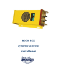
BOOM BOX 3 Dynamite Controller User’s Manual Revision 1.02 Boom Box 3 Dynamite Controller User’s Manual Printed in U.S.A. ©2013 Seismic Source Co. • All rights reserved. This document may not be reproduced in any form without prior, express written consent from Seismic Source Co. Seismic Source reserves the right to make changes and improvements to its products without providing notice. Trademarks Boom Box 3 is trademark of Seismic Source Co. Seismic Source Co. 2391 E. Coleman Rd. Ponca City, OK 74604 USA Telephone: (580) 762-8233 Fax: (580) 762-1785 Email: [email protected] www.seismicsource.com 2 Table of Contents TABLE OF CONTENTS ........................................................................................ 3 1. SAFETY ............................................................................................................ 5 2. BOOM BOX 3 SYSTEM DESCRIPTION ........................................................... 6 2.1.1 Boom Box 3 and Boom Box differences ............................................................................... 6 2.2.1 BB3 Autonomous Mode: ....................................................................................................... 8 2.3.1 Standard Radio Mode: ........................................................................................................... 8 2.4.1 Encoder System consists of the following: ............................................................................ 9 2.4.2 Decoder System consists of the following: .......................................................................... 10 3. FRONT PANEL DESCRIPTION ...................................................................... 11 3.1.1 Display ................................................................................................................................. 12 4. ENCODER OPERATION ................................................................................. 13 5. DECODER OPERATION ................................................................................. 14 5.1 Decoder Operation ................................................................................................................. 14 5.2 Detailed Decoder Operation .................................................................................................. 15 5.2.1 Uphole Geophone Test ........................................................................................................ 15 5.2.2 CAP Resistance Test ............................................................................................................ 15 5.2.3 GPS Test .............................................................................................................................. 15 5.2.4 Fire Sequence – VP/ UE Mode - Decoder ........................................................................... 16 6. AUTONOMOUS DECODER OPERATION ...................................................... 17 6.1 Autonomous Decoder Operation .............................................................................................. 17 6.2. Detailed Autonomous Decoder Operation .............................................................................. 19 6.2.1 Uphole Geophone Resistance Test ...................................................................................... 19 6.2.2 CAP Resistance Test ............................................................................................................ 19 6.2.3 GPS Test .............................................................................................................................. 19 6.2.4 Fire Sequence -Autonomous Decoder ................................................................................. 20 7. BOOM BOX 3 PARAMETERS ........................................................................ 21 7.1.1 Boom Box 3 Parameters ...................................................................................................... 21 8. HARDWARE INSTALLATION......................................................................... 23 3 BOOM BOX 3 Dynamite Controller 9. WI-FI INTERFACE ........................................................................................... 26 9.1. Software Installation and Setup .............................................................................................. 26 9.1.1 Connecting to a Unit through Web Browser ........................................................................ 26 9.2. PFS Information Display ......................................................................................................... 27 9.3. Parameter setup ........................................................................................................................ 28 9.4. Autonomous Mode Setup ......................................................................................................... 29 9.4.1 Fleet Units Assignment ........................................................................................................ 30 9.4.1 Next Shot Assignment ......................................................................................................... 30 10. COMPUTER SOFTWARE ............................................................................. 31 10.1 SourceLink Software ............................................................................................................... 31 11. BOOM BOX 3 DECODER CABLE ................................................................ 32 12. DECODER CABLE WITH GPS ..................................................................... 33 12.1 Boom Box 3 Decoder Cable..................................................................................................... 34 12.2 Boom Box 3 – 10 pin wiring .................................................................................................... 36 User’s Manual 4 1. Safety Because this equipment is used with explosives, extreme caution must be observed. Make sure you know the safety regulations, and follow them. Follow the correct procedures. Shooters and helpers must wear hard hats. Keep non-essential people well away from the shot point (both members of the public and crew personnel). Keep CAP lines shorted together at all times when it is not safe to Fire the shot. Only connect CAP lines to the Boom Box 3 when it is safe to Fire the shot. Never press the ARM or Charge switch on the Boom Box 3 unless it is safe to Fire the shot. Only shoot when ready and safe. Observe local safety regulations. Do not shoot in stormy weather. Do not fire shots close to power lines without ensuring that there is no possibility of cap wires coming into contact with the power lines. Do not shoot close to high-power radio transmitters. After the shot: o Make sure all the charges at a multiple/pattern shot have detonated. o Keep a record of any shots, which it was not possible to fire. They must be disposed of safely. The Seismic Source Company does not represent that this manual is entirely comprehensive, accurate or covers each and every safety topic or risk which may be encountered by those using this manual and the Seismic Source Company disclaims all responsibility and liability for any such utilization of this information by the users thereof. By receipt of the Boom Box 3 Manual, the recipient/user agrees to release, indemnify and defend the Seismic Source Company from and against any and all claims, demands and liabilities that may arise from the utilization of the Boom Box 3 System by such recipients/users. The end user uses the Boom Box 3 System at his/her own risk. The Seismic Source Company does not assume any responsibility for accidental firings or any accident occurring with the Boom Box 3 System. 5 BOOM BOX 3 Dynamite Controller 2. Boom Box 3 System Description The Boom Box 3 (BB3) is a new generation of Blasters for Seismic Exploration. The BB3 is specifically designed to operate more efficiently with autonomous continuous Seismic Recording systems. The BB3’s main features are: Internal Clock is synchronized to GPS time All Shot data including shot times to microsecond accuracy is stored in non-volatile memory in the unit. WiFi HTML interface that allows viewing of shot information and setting BB3 parameters on many Cell phones, PCs, or Tablet computer Shot timing is synchronized to GPS clock for firing on 8 msec sample boundaries. This assures no sample skew on most autonomous seismic recording systems Compatible with older Boom Box units in standard VP radio mode. This allows the newer BB3 units to operate with the older Boom Box equipment on the same crew. Multiple Modes of operation o Autonomous mode – Decoder unit’s use GPS time to fire the shots. No Encoder unit or Radio telemetry is required. Multiple shooters can be used with no overlap of shot times. o Standard Radio Mode – (UE/VP Mode) Decoders receive start commands from central Encoder unit via a VHF/UHF radio. Compatible with older Boom Box units operating in VP mode. o F3 Radio Mode. The F3 radio mode is used to start the Boom Box 3 on an exact GPS time. The Encoder and radio are still used to send the radio start codes to the Decoder unit. The precise GPS time of the Fire is sent to the Decoder and the Decoder unit fires the shot at the precise time requested. This mode is especially useful when using digital radios with unknown or variable modulation delays. 2.1.1 Boom Box 3 and Boom Box differences There are important differences between the Boom Box 3 and the older Boom Box unit Decoder Cable The BB3 Decoder cable has an added wire for the PPS pulse from the GPS receiver. The BB3 can operate with the older Boom Box decoder cable, but the GPS time will not be set. The BB3 will communicate and operate the same as the older Boom Box unit with the old Boom Box cable. The new BB3 decoder cable should not be used with the older Boom Box units. The PPS pulse from the GPS will be grounded by the older Boom Box units. This could damage the GPS receiver. Parameter Loading The basic parameters of the BB3 can be loaded using the older Source Control software. However many of the new parameters of the BB3 must be loaded using either the WiFi interface or the SourceLink software. User’s Manual 6 GPS Baud Rate The BB3 is set to use GPS receivers set at 19.2 K baud rate The older boom box is set to use GPS receivers set at 9600 baud rate Geophone Test The BB3 includes a detailed geophone tests. These tests assure that the uphole geophone is planted correctly and is operational. The Geophone tests the following parameters: Resistance – measures DC resistance – Geophone must be connected Frequency – geophone must be planted in vertical position for frequency to pass Damping - geophone must be planted in vertical position for damping to pass Sensitivity -geophone must be planted in vertical position for sensitivity to pass The older Boom Box unit only tested the Geophone resistance Radio Telemetry The BB3 uses a new radio telemetry interface. This new interface is designed to provide a robust and reliable connection to most VHF and UHF radios. The BB3 uses the same radio telemetry design as the Force 3 vibrator electronics. When the BB3 is set to maximum radio modulation level, the radio interface requires a similar interface as the older Boom Box units. The same “Radio Pigtails” should work for both the BB3 and the Boom Box unit. The BB3 may require different radio polarity than the older Boom Box units. The Microphone and Speaker polarity should be tested for optimum operation. When different radios or different radio polarities are used with the BB3 units, there may be a start time difference between the BB3 and the older Boom Box units. The “Decoder Delay” entry of the Boom Box 3 can be used to match the start times of the older Boom Box units. 7 BOOM BOX 3 Dynamite Controller 2.2.1 BB3 Autonomous Mode: The Boom Box 3 can be used in Autonomous mode. In this mode the Decoder units use GPS time to fire the shots. No Encoder unit or Radio telemetry is required. Multiple shooters can be used with no overlap of shots times. The Units and Record length can be assigned using the User Interface software. For further details refer to BB3 autonomous Mode section. 2.3.1 Standard Radio Mode: The Boom Box 3 system is used to synchronize and control dynamite operation on seismic recording crews. A typical system includes at least one Boom Box 3 set up as a Decoder, and one Universal Encoder II (UE2) for the Encoder. The Encoder unit interfaces the Seismic Recording System with a radio system, which communicates to the Decoder system. The Recording System sends a start command to the Encoder, which causes the Encoder to send a fire command to the Decoder. The Decoder receives the Fire command, and will fire the CAP if the Decoder unit is ARMED and Charged. At the same time that the Decoder unit fires the CAP, the Encoder issues a Time Break signal to the Recording System. After the shot is fired the Decoder records the signal from the Uphole Geophone and transmits this data along with other QC data to the Encoder. User’s Manual 8 2.4.1 Encoder System consists of the following: Universal Encoder 2 Recording System Interface: o Remote Start – signal from Recording System, which starts Boom Box 3 Encoder. o Time Break – T.B. – signal from Boom Box 3 Unit when voltage is applied to High Voltage for Cap firing. o Aux 1 – Analog Uphole – Analog line where uphole geophone signal is reproduced at 1.5 seconds after Time Break. An analog pulse at 1.0 second is used to check timing accuracy of system and another analog pulse at 1.25 seconds confirms that current flowed to the CAP. o Aux 2 – Timing pulses at 1.0, 1.25, 1.5 seconds after Time Break. o COM 2 – Recording System Serial Interface plug. Connects to Recording System for data communication. o Ethernet Port Setting Encoder parameters Viewing and storing Shot Status Report Viewing and storing GPS position Monitoring Recording Truck Serial Message Viewing Decoder Ready Messages Monitoring Start Time Errors Battery – 9-36 volt DC voltage Radio – Encoder - Unit connects to UHF or VHF radio to communicate with the radio connected to the Decoder. GPS and cable. Used to synchronize the clock of the UE2 unit. UE2 Encoder Cable: 9 BOOM BOX 3 Dynamite Controller 2.4.2 Decoder System consists of the following: Boom Box 3 Unit configured as Decoder Boom Box 3 Decoder Cable Boom Box 3 Decoder backpack. Designed to carry all components of the Decoder System. Uphole Geophone – Geophone sensor used to measure time from when shot is fired to when motion is received at surface. Battery – 9-36 VDC battery used to power Boom Box 3 Decoder Radio – Decoder unit connects to UHF or VHF radio to communicate with the radio connected to the Encoder Unit. CAP line – CAP line to fire dynamite is connected to High Voltage post on Decoder Unit. GPS receiver – optional –External GPS receiver can be connected to Decoder Unit. GPS position can be acquired prior to shot. Position is sent back to Encoder Unit as part of the Ready Message and Shot Status Report. The Ready Message consists of the GPS position, Unit ID #, CAP resistance, and Geophone resistance. GPS PPS pulse from the GPS receiver is used to synchronize the time of the shots. The GPS PPS pulse and GPS unit is required when the BB3 is used in Autonomous mode. Autonomous Decoder Fire Switch (required when the BB3 is used in Autonomous mode) User’s Manual 10 3. Front Panel Description Boom Box 3 Front Panel contains: 2 High Voltage terminals – connect to CAP wire for firing dynamite. Red Power/Status LED o Decoder Mode – flashes ON in short bursts. o Decoder Mode Charging – Flashes Fast when charged ARM toggle switch o Power up Boom Box 3 – single press powers the box “on” o Arm the dynamite CAP line – must hold switch to “ARM” high voltage terminals o The ARM switch in the normal position shorts the high-voltage line Charge toggle switch o Press Charge to charge the High Voltage Capacitor Test Push Button o Press Test button to test the Geophone o Press Test and ARM button to test the dynamite CAP o Test LED shows result of test GPS Push Button o Press GPS button to store the GPS position for the next shot o GPS LED shows status of GPS position 11 BOOM BOX 3 Dynamite Controller 3.1.1 Display The Boom Box 3 has a graphical display. The display is used to show the setup of the box at power on, the CAP and Geophone resistance, the ready message, the uphole information, and the shot status message. The display shows the following messages: Unit ID # - Unit ID of the Boom Box 3 Crew Code # - The Crew # of the Encoder must match the Crew Code of the Decoder Start Code # - The Start Code # of the Encoder must match the Start Code of the Decoder Operating mode : “ENC”-Encoder, “DEC”-Decoder ,“STN”-Standalone/Autonomous , “AGD”-Air Gun Decoder “MON”-Monitor Battery : Battery voltage indicator GPS : Shows the following: Quality of the GPS ‘1’ :GPS Fix ‘2’:Differential , p-PPS available Time Synchronization: “T: OK” –Time Synchronized, “T:NO” –No time sync Lock status:”Lock” -GPS position is locked for the next shot. Cap Resistance Decoder will display Geophone resistance when the Arm and Test button is pressed. Geophone Resistance Decoder will display Geophone resistance when the Test button is pressed. Geophone test also provides “Fr”-Frequency “Da”-Damping “Sen”-Sensitivity User’s Manual 12 4. Encoder Operation The following Encoders can be used to fire the Boom Box 3 Decoders via radio Universal Encoder 1 (in VP mode) Universal Encoder 2 Boombox3 unit with SourceLink™ Software 13 BOOM BOX 3 Dynamite Controller 5. Decoder Operation 5.1 Decoder Operation The Decoder Mode of operation is used to detonate a blasting cap for seismic dynamite operation. Extreme caution needs to be exercised when working around dynamite and detonation equipment. Review and follow all safety guidelines. The Decoder unit is connected to a detonation Cap, an uphole geophone, a radio, and a battery. Whenever the Decoder is connected to the CAP or whenever a radio is used, the CAP can fire at any time. The unit has been designed to only fire the CAP when both the ARM and the Charge button are held and a valid start code from the Encoder is received. However, potentially there is a chance that the CAP can accidentally fire from either RF noise or a hardware failure. With this in mind the following is the normal A3/UE mode operation procedure: The Shooter receives a valid GPS position for the new shot point. The Shooter verifies that there is no danger in accidental firing of hole and that all personnel and livestock are clear of the shot hole. The “Shooter” connects the unit to the uphole geophone, and Cap at the new shot hole. The Shooter normally checks the resistance of both the geophone and the Cap. After all tests are satisfactory, the shooter either calls in that he is ready or uses the automatic ready signal to notify the recorder that he is ready to shoot. The Shooter then presses the “Arm” and “Charge” switches to get the box ready to fire. The Boom Box 3 will automatically send back a “Ready Message” if enabled. The Encoder then sends a start code and the Decoder fires the Shot. The shooter then releases the “Arm” and “Charge” switch and disconnects from the hole. The Decoder unit automatically sends the Shot Status Message to the Encoder. The Shooter can check the status of the Box immediately after the Shot is fired. o Test LED = Green when Confirmation Time Break is valid. o GPS LED = Green when Uphole time is valid o The display will show the Uphole time, CTB value, and battery voltage. User’s Manual 14 5.2 Detailed Decoder Operation 5.2.1 Uphole Geophone Test Press Test button on Front Panel to test Uphole Geophone Boom Box 3 Compares reading with internal limits Flashes Test LED green 4 times if result is within entered limit Flashes Test LED red 4 times if is outside entered limits Geophone Test includes o Resistance – measures DC resistance o Frequency – geophone must be planted in vertical position for frequency to pass o Damping - geophone must be planted in vertical position for damping to pass o Sensitivity -geophone must be planted in vertical position for sensitivity to pass Geophone resistance will be shown on the Armed and Ready display. 5.2.2 CAP Resistance Test Press Test button and ARM switch on Front Panel to test CAP resistance Boom Box 3 Compares reading with internal limits Flashes Test LED green 2 times if result is within entered limit Flashes Test LED red 2 times if result is outside entered limits CAP resistance will be shown on the Armed and Ready display. 5.2.3 GPS Test Press GPS button to acquire new GPS position – 10 seconds. GPS LED is RED for the first 4 seconds to show the GPS button was pressed. Solid green GPS LED with a differential position. Flashing green GPS LED with a non-differential position. Solid red GPS LED when a bad position was received. No GPS LED when no GPS information is received within 10 seconds of pressing the GPS button. The GPS LED’s will stay this way until pressing the GPS button again or taking the next shot. Note: Boom Box 3 is normally set up for GPS receivers using 19.2 k baud 15 BOOM BOX 3 Dynamite Controller 5.2.4 Fire Sequence – VP/ UE Mode - Decoder Press both the Arm and Charge switch to Arm Boom Box 3 and charge internal capacitor. If the Ready Message is enabled the Ready Message will be automatically sent when the high voltage capacitor is fully charged and box is ready to fire. When valid Start Code is received from the Encoder unit, the shot sequence is started and the High Voltage is applied to the Cap line the Shot is fired. Test LED will flash green for 4 seconds after shot if Confirmed Time Break is OK Test LED will flash RED after shot if Confirmed Time Break is not detected GPS LED will flash green after shot if first break is detected on Uphole geophone GPS LED will flash red after shot if first break is not detected The display will show Uphole time, CTB value, and Battery voltage. User’s Manual 16 6. Autonomous Decoder Operation See Autonomous Mode Setup section of this manual 6.1 Autonomous Decoder Operation The Autonomous Decoder Mode of operation is used to detonate a blasting cap for seismic dynamite operation. Extreme caution needs to be exercised when working around dynamite and detonation equipment. Review and follow all safety guidelines. The Decoder unit is connected to a detonation Cap, an uphole geophone and a battery. Whenever the Decoder is connected to the CAP or whenever a radio is used, the CAP can fire at any time. The unit has been designed to only fire the CAP when both the ARM and the Charge button are held .However; potentially there is a chance that the CAP can accidentally fire from either RF noise or a hardware failure. With this in mind the following is the normal operation procedure: The Shooter receives a valid GPS position for the new shot point. The Shooter verifies that there is no danger in accidental firing of hole and that all personnel and livestock are clear of the shot hole. The “Shooter” connects the unit to the uphole geophone, and Cap at the new shot hole. The Shooter normally checks the resistance of both the geophone and the Cap. After all tests are satisfactory, the shooter calls in that he is ready(optional) The Shooter sets the Line/Station information of the shot either manually or automatically using the Wi-Fi or Computer interface. The Shooter then presses the “Arm” and “Charge” switches to get the box ready to fire. The Shooter then presses the Autonomous Decoder Fire switch to initiate the sequence (For added safety). The Boombox 3 will start looking for the next available GPS time Slot, based on the preprogrammed Unit List and Record Length. The Unit will pick the nearest available time slot, but if the next slot is less than 10 seconds away, this slot is ignored and the next to next slot (calculated based on units, record length) is picked instead ,for safety reasons. The Boombox 3 display will update the remaining seconds for the Fire Slot. The Shot will be fired at the Fire Slot GPS Time if the Arm & Charge button are held . The Arm & Charge switch must be hold at least for the last 4 seconds before the fire, for the fire to happen. If not the shot will be cancelled for safety reasons. The shooter then releases the “Arm” and “Charge” switch and disconnects from the hole. The Decoder unit automatically saves the GPS Time,Postion ,Line/Station information, uphole information in the Flash Card. The shot information is updated in the Wifi Interface Software. The Shooter can check the status of the Box immediately after the Shot is fired. o Test LED = Green when Confirmation Time Break is valid. o GPS LED = Green when Uphole time is valid o The display will show the Uphole time, CTB value, and battery voltage. 17 BOOM BOX 3 Dynamite Controller User’s Manual 18 6.2. Detailed Autonomous Decoder Operation 6.2.1 Uphole Geophone Resistance Test Press Test button on Front Panel to test result Uphole Geophone Boom Box 3 Compares reading with internal limits Flashes Test LED green 4 times if result is within entered limit Flashes Test LED red 4 times if is outside entered limits Geophone resistance will be shown on the display. 6.2.2 CAP Resistance Test Press Test button and ARM switch on Front Panel to test CAP resistance Boom Box 3 Compares reading with internal limits Flashes Test LED green 2 times if result is within entered limit Flashes Test LED red 2 times if result is outside entered limits CAP resistance will be shown on the display. 6.2.3 GPS Test Press GPS button to acquire new GPS position – 10 seconds. GPS LED is RED for the first 4 seconds to show the GPS button was pressed. Solid green GPS LED with a differential position. Flashing green GPS LED with a non-differential position. Solid red GPS LED when a bad position was received. No GPS LED when no GPS information is received within 10 seconds of pressing the GPS button. The GPS LED’s will stay this way until pressing the GPS button again or taking the next shot. 19 BOOM BOX 3 Dynamite Controller 6.2.4 Fire Sequence -Autonomous Decoder Set the Line/Station information of the shot either manually or automatically using the using Wi-Fi or Computer interface. Press both the Arm and Charge switch to Arm Boom Box 3 and charge internal capacitor. Press the Autonomous decoder fire switch. The Boom Box 3 Unit will fire the shot in the correct GPS time slot. The Shooter can check the status of the Box immediately after the Shot is fired. o Test LED = Green when Confirmation Time Break is valid. o GPS LED = Green when Uphole time is valid o The display will show the Uphole time, CTB value, and battery voltage. The display will show Uphole time, CTB value, and Battery voltage. User’s Manual 20 7. Boom Box 3 Parameters The Boom Box 3 Unit uses internally stored parameters to determine the operation of the unit. All of the parameters are stored in nonvolatile memory and only need to be changed when an operational parameter changes. The internal parameters can only be modified using an external computer. Two different programs and methods are available for changing the operational parameters. Cell Phone/Tablet Wifi interface –Refer Wifi Interface section of the manual Windows Computer interface – Refer Computer Interface section of the manual 7.1.1 Boom Box 3 Parameters Unit ID (1-32) – Used to set Box ID – ID # is used to identify records. o Requested Unit ID in Fire Command from Encoder must match Decoder Unit ID to Fire shot. o Other Brand Compatible Mode – When the other brand Encoder has Box ID number 15 in the start code that is sent to the Boom Box 3, the Boom Box 3 decoder will allow any decoder box ID to always fire. Crew ID (0-250) – Used to set Crew ID. o Requested Crew ID in Fire Command from Encoder must match Decoder Unit ID to Fire shot. o Other Brand Compatible Mode – Crew ID 15 in Decoder will allow box to fire. Start Code (0-3) – Used to set Start Code. o Requested Start Code in Fire Command from Encoder must match Decoder Unit ID to Fire shot. Password (8 digit) – Allows Software program to hide the Advanced entries from user. o “BoomBox3” – Always allows the user to enter the Advanced entries.Case sensitive password. Decoder Start Delay – (0 – 4,000 microseconds) used by Decoder Boom Box 3.. o Allow individual Decoders to be delayed. o Normally set to zero. Uphole Blank Time – 0 – 99 msec, in1 msec increments. o Sets the Uphole data to zero for the selected amount of time. o Typically set = 0 msec. Uphole Window Delay – 0 – 127 msec. o Delays when the 60 msec Uphole window is recorded. Entry allows recording data up to 127+60=187 msec. o Entry of 255 allows automatic Uphole Window Delay. The first pick is placed in the middle of the 60 msec window sent back to the Encoder. o Typically set = 0msec. Operating Mode o Encoder o Standard Decoder o Autonomous Decoder o Air Gun Decoder o Monitor Auto Shut Down – (0-255 minutes) 21 BOOM BOX 3 Dynamite Controller o Decoder unit will automatically power down after this time to conserve battery power. o Any switch movement will reset the time to shut down. o Normally set to 10 minutes. o 0 is always ON. First Break Threshold o 10% of peak Threshold (Data Peak/10 with Backup ) o 20% of peak Threshold (Data Peak/5 with Backup ) Interface Function: o Recorder Start Active – not currently used. High – low to high transition will start external recorder. o Time Break Active. High – low to high transition at time 0 when shot is fired. Low – high to low transition at time 0 when shot is fired. Decoder always-active LOW. o Remote Start Active – signal to Boom Box 3 Recorder, which starts the Fire Command sequence. High – low to high starts fire command sequence. Low – high to low starts fire command sequence. o Speaker Polarity – selects speaker polarity for the radio reception. Typically the Boom Box 3 will receive data better on one polarity than the other. A distance test should be performed to determine optimum performance. o Microphone Polarity – Sometimes it is better to switch microphone polarity than speaker polarity. Normally set to Normal. Geophone Limit Min (0 – 870) ohm. Sets minimum limit in ohms for the uphole geophone resistance measurement. Determines if the Boom Box 3 Decoder test the uphole geophone as good or bad. Flashes Test LED 4 times green for good or flashes 4 times red for bad. o Typical = 50 ohm – depends on uphole geophone. Geophone Limit Max (0 – 870) ohm. Sets maximum limit in ohms for the uphole geophone resistance measurement. Determines if the Boom Box 3 Decoder test the uphole geophone as good or bad. Flashes Test LED 4 times green for good or flashes 4 times red for bad. o Typical = 500 ohm – depends on uphole geophone. Cap Limit Min (0 – 100) ohm. Sets minimum limit in ohms for the blasting cap resistance measurement. Determines if the Boom Box 3 Decoder test the blasting cap as good or bad. Flashes Test LED 2 times green in good or flashes 2 times red for bad. o Typical = 2 ohm Cap Limit Max (0 – 100) ohm. Sets maximum limit in ohms for the blasting cap resistance measurement. Determines if the Boom Box 3 Decoder test the blasting cap as good or bad. Flashes Test LED 2 times green for good or flashes 2 times red for bad. o Typical = 30 ohm User’s Manual 22 8. Hardware Installation J1M1 BAT - 1 TX0 COMPUTER 2 RX0 COMPUTER 3 GPS A RX 4 GPS A TX 5 GPS Control TX 6 GPS Control RX 7 TX2 RTI/IR PORT 8 RX2 RTI/IR PORT 9 ISO_STA RT_ACT 10 ISO_STA RT_RET 11 ISO_SPAREIN_ACT 12 ISO_SPAREIN_RET 13 ISO_TB_ACT 14 ISO_TB_RET 15 NISO_TB _A 16 ISO_RECSTART_A CT 17 ISO_RECSTART_RET 18 BAT + 19 O O O O O O O O O O O O O O O O O O O O O O O O O O O O O O O O O O O O 20 BAT - 21 UPHOLE+ 22 UPHOLE- 23 +5 VD 24 GPS_PPS 25 SPKR_ACT 26 SPKR_RET 27 PTT_ACT 28 RADIO_RET 29 MIC_ACT 30 RADIO_UPHOLE 31 TTL OUT 1 (Currently not used) 32 TTL OUT 2 (Currently not used) 33 ISO_REF_PULSES_ACT 34 ISO_REF_PULSES_RET 35 NISO_REF_PULSES +5VD 36 NISO_RECSTART 37 BAT + O CONEC 4STF37PCT05S20X BOOM BOX 3 37-PIN CONNECTOR PIN 1 2 FUNCTION BAT - - Battery Ground. TX0 COMPUTER – RS-232 serial output. Data from Boom Box 3 to Computer. Connect to COM port of computer running the BBview program. 19200 BAUD. RX0 COMPUTER – RS-232 serial input. Data to Boom Box 3 from Computer. Connect to COM port of computer running the BBview program. 19200 BAUD. See GPS connections at end of this chapter. TX2 RTI/IR PORT – RS-232 output. Data from Boom Box 3 to Recording System. Recording system selected by software menu. RX2 RTI/IR PORT – RS-232 input. Data to Boom Box 3 from Recording System. Recording system selected by software menu. For this pin to be active JMP2 has to be shorted on pins 1 and 2. ISO_START_ACT – Isolated input. Isolated Start Active. Recorder remotely starts the Boom Box 3 in Encoder mode. Isolated with 6N137 optocoupler. Polarity selected by software menu. ISO_START_RET - Isolated Start Return. 3 4 8 9 10 11 23 BOOM BOX 3 Dynamite Controller 12 13 14 15 16 17 18 19 20 21 22 23 25 26 27 28 29 30 31 32 33 34 35 36 ISO_SPARE_IN_ACT – Isolated input. Isolated Spare IN Active. Used in Weight Drop Mode to start the Weight Drop process. Connected to the start switch. Isolated with 6N137 optocoupler. Polarity selected by software menu. ISO_SPARE_IN_RET – Isolated Spare IN Return. ISO_TB_ACT – Isolated output. Isolated Time Break Active. Used in Encoder and Decoder modes. Isolated with 4N32 optocoupler. Polarity selected by software menu in Encoder Mode. Polarity is always active low in Decoder mode. ISO_TB_RET – Isolated Time Break Return. NISO_TB_A – Non-isolated Time Break. Used in Encoder and Decoder modes. Polarity selected by software menu in Encoder Mode. Polarity is always active low in Decoder mode. +3.3 volts to 0 volts. ISO_RECSTART_ACT – Isolated output. Isolated Recorder Start Active. Pre-Start pulse in Encoder, Master, Repeater, and Slave modes. Isolated with 4N32 optocoupler. Polarity selected by software menu. ISO_RECSTART_RET – Isolated Recorder Start Return. BAT + - Not connected on Version 2 cards - Jumper J12 on board if needed. BAT - - Battery Ground. UPHOLE + - Input. Uphole Geophone connection. –1.566 volts to +1.526 volts. UPHOLE - - Input. Uphole Geophone connection. +5VD – Output. +5 volts digital. SPKR_ACT – Input. Speaker Active to Boom Box 3 from external radio speaker output. . SPKR_RET – Speaker return. Speaker return from external radio speaker return. PTT_ACT – Output. Push To Talk Active from Boom Box 3 to external radio. RADIO_RET – Radio return. Radio return from external radio ground MIC_ACT – Output. Microphone Active from Boom Box 3 to external radio microphone input. RADIO_UPHOLE – AUX 1 output. Encoder, Master, and Repeater produce the Uphole signal after the decoder fires the shot and returns the post report. 1.65 volts to +1.65 volts. TTL_OUT 1 – Not currently used. TTL_OUT 2 - Not currently used. ISO_REF_PULSES_ACT – AUX 2 isolated output. Reference pulses Active. Occurs in Encoder, Master, and Repeater modes at 1, 1.25, and 1.5 seconds after the Fire sequence. Uses a 4N32 optocoupler. ISO_REF-PULSES_RET – Reference pulses Return. Pins 33 and 34 are used to enable or disable the infrared port. Pins 33 and 34 shorted and the infrared port is disabled and the data can go the recording system. Pins 33 and 34 open and the infrared port are enabled. NISO_REF_PULSES – AUX 2 non-isolated output. Reference pulses. Occurs in Encoder, Master, and Repeater modes after the Fire sequence. 0 to +3.3 volts. NISO_RECSTART – Non-isolated output. Recorder Start Active. Pre-Start pulse in Encoder, Master, Repeater, and Slave modes. Polarity selected by software menu. +3.3 volts to 0 volts. User’s Manual 24 Not connected on Version 2 boxes -BAT + - - Battery positive – DC power input on Boom Box 3 (10-37 volts DC). Jumper J11 on board if needed. 37 GPS Connections: External GPS with external corrections. 4 GPS A RX – Not used. 5 GPS A TX – RS-232 serial input, 19200 BAUD. GPS data from external GPS Receiver to Boom Box 3. GGA, RMC strings required. 6 GPS Control TX – Not used. 7 GPS Control RX – Not used. 24 GPS_PPS – Input. PPS pulse (Active High) from external GPS receiver. BOOM BOX 3 10-PIN CONNECTOR PIN A B DC). C FUNCTION GPS_PPS-Input. PPS pulse (Active High) from external GPS receiver. BAT + - - Battery positive – DC power input on Boom Box 3 (10-37 volts MIC_ACT – Output. Microphone Active from Boom Box 3 to external radio microphone input. UPHOLE - - Input. Uphole Geophone connection. GPS A TX – RS-232 serial input, 19200 BAUD. GPS data from external GPS Receiver to Boom Box 3. UPHOLE + - Input. Uphole Geophone connection. –1.566 volts to +1.526 volts. SPKR_ACT – Input. Speaker Active to Boom Box 3 from external radio speaker output. BAT - - Battery Ground. PTT_ACT – Output. Push To Talk Active from Boom Box 3 to external D E F G H J radio. K SPKR_RET – Speaker return. Speaker return from external radio speaker return. 25 BOOM BOX 3 Dynamite Controller 9. Wi-Fi Interface The Boom Box 3 Wifi Interface can be used to Load operating parameters View uphole data View current status of resistance test Load and store all uphole information from Boom Box 3 9.1. Software Installation and Setup BoomBox3 Wi-Fi interface does not need any installation. The built in Wi-Fi interface of BoomBox 3 unit can communicate with Web Browsers(Internet Explorer ,Safari ,Google Chrome, etc.) in most common Cell phones, Tablets and Computers with Wi-Fi connectivity. 9.1.1 Connecting to a Unit through Web Browser Open the Wireless network selection menu in your Cell Phone/Tablet/Computer. Connect to the Network with the SSID -“BoomBox6xxx”. Open your web browser (Internet Explorer ,Safari ,Google Chrome, etc.) Type in 192.168.1.1 into your web browser and open the page. It is recommended to add this 192.168.1.1 page to your favorites and create an icon. Boombox Wi-Fi interface software will be ready to use now. For changing any advance parameters a password may be required.The factory set password is “BoomBox3” .Password is case sensitive. User’s Manual 26 9.2. PFS Information Display After each shot BoomBox3 automatically sends the PFS Information through wifi interface which can be analyzed in a web browser and stored for future reference. 27 BOOM BOX 3 Dynamite Controller 9.3. Parameter setup BoomBox3 parameters can be received and sent through the wifi interface. To set advanced parameters ,the software requests a password.The factory set password is “BoomBox3”. For a detailed description of parameters please refer BoomBox Parameters section of the manual. User’s Manual 28 9.4. Autonomous Mode Setup Autonomous mode operation allows shooters to fire shots independently based on dedicated GPS time slots. This mode involves more shooter interaction with user interface software that other conventional modes. First the BoomBox3 parameters can be set, with the standard parameters and the mode selected to “Autonomous Decoder”. 29 BOOM BOX 3 Dynamite Controller 9.4.1 Fleet Units Assignment Once the Operation mode is set to Autonomous Decoder, the Units in the fleet and the record length (typically listen time) needs to be setup. This allows the Boombox3 unit to calculate GPS time slots for firing the shots. 9.4.1 Next Shot Assignment Before each shot the Shooter needs to assign Line/Station associated with the shot.This can be done manually or automatically using the Map feature. User’s Manual 30 10. Computer Software Boombox3 can be directly interfaced by connecting to a computer through Ethernet port. 10.1 SourceLink Software SourceLink software can be used to communicate with BoomBox3 directly. SourceLink software has a wide variety of features to support all recording system requirements. Boombox3 to RJ45 cable needs to be connected to the computer. The IP Address of the computer needs to assigned as 10.x.x.x and Subnet Mask 255.0.0.0. All Firewalls and Anti Virus needs which could block Ethernet communication needs to be turned off. For complete instructions please refer to SourceLink Reference Manual 31 BOOM BOX 3 Dynamite Controller 11. Boom Box 3 Decoder Cable 10 pin Decoder Cable 4 feet long B Red H BLK Battery plus Battery minus F Red D BLK Uphole + Uphole – C Red A BLK Mic Act PPS Input J White PTT Active BLK no connect G Green K BLK Speaker Pos Speaker Return 5 pin Radio Cable Wiring Mic Active – Radio Return - C A Speaker ActSpeaker Ret- B E PTT D User’s Manual 32 12. DECODER CABLE with GPS 10 pin Decoder Cable 4 feet long B Red H BLK Battery plus Battery minus F Red D BLK Uphole + Uphole – GPS input B White H Shield E BLK A BLK Battery plus – (optional 9 pin Female) pin 9 GND ( Battery minus) - (optional 9 pin Female) pin 5 GPS input to Boom Box 3 - (optional 9 pin Female) pin 2 PPS Input RADIO C Red Mic Act J White BLK PTT Active no connect G Green K BLK Speaker Pos Speaker Return (Optional) 5 pin Radio Cable Wiring Mic Active – Radio Return - A C Speaker ActSpeaker Ret- B E PTT D 33 BOOM BOX 3 Dynamite Controller 12.1 Boom Box 3 Decoder Cable User’s Manual 34 35 BOOM BOX 3 Dynamite Controller 12.2 Boom Box 3 – 10 pin wiring User’s Manual 36