1
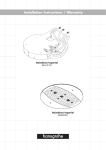
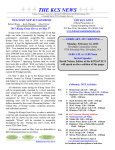
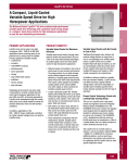
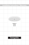
Operation and Maintenance Manual
Ultraviolet Disinfection System
EC- Series
HORIZONTAL CHANNEL SYSTEMS
PACKAGE PLANTS
130 West Main Street
Silverdale, PA 18962
(215) 453-2533 Fax (215) 453-1101
www.enchlor.com
Manufactured in the USA
2
TABLE OF CONTENTS
LAMP CHANGE DATE TABLE ......................................................................................3
1 IMPORTANT INFORMATION....................................................................................4
2 ABOUT ULTRAVIOLET (UV) DISINFECTION ..........................................................4
3 PRE-INSTALLATION GENERAL INFORMATION....................................................5
3.1
3.2
3.3
3.4
3.5
3.6
3.7
!WARNING! .............................................................................................................5
UV EFFECTIVENESS ...............................................................................................5
SYSTEM DESIGN .....................................................................................................6
FLOW RATE ............................................................................................................6
ELECTRICAL REQUIREMENTS ...................................................................................6
INSPECTION ............................................................................................................6
DISPOSAL...............................................................................................................6
4 SYSTEM COMPONENTS ..........................................................................................6
5 STAINLESS STEEL CHANNEL OR MODULAR SUPPORT SYSTEM.....................7
5.1 WEIR .....................................................................................................................9
5.2 LAMP MODULES ......................................................................................................9
5.3 LAMPS AND QUARTZ SLEEVES INSPECTION AND INSTALLATION .................................11
5.4 QUARTZ SLEEVE MAINTENANCE .............................................................................12
5.4.1 Manual Cleaning ..........................................................................................12
5.4.2 Automated Cleaning – Optional Equipment .................................................12
5.4.3 Automatic Cleaning – Optional Equipment...................................................12
5.4.4 Removal of Module for Cleaning ..................................................................13
6 POWER CONTROL CENTER (PCC).......................................................................14
PCC DISPLAYS ............................................................................................................15
6.1.1 Lamp-out Indicators......................................................................................15
6.1.2 Running Time Meters...................................................................................15
6.1.3 Ultraviolet Monitor ........................................................................................15
6.2 PCC ELECTRICAL .................................................................................................16
6.2.1 Over-Current and Ground Fault Protection ..................................................16
6.2.2 Electronic Ballast..........................................................................................16
7 ATTACHMENTS ......................................................................................................17
8 TROUBLESHOOTING UV HORIZONTAL CHANNEL SYSTEM: ...........................18
WARRANTY REGISTRATION......................................................................................20
WT O&M Manual Version November 2006
3
LAMP CHANGE DATE TABLE
Date System Installed:_________________________
LAMP CHANGE DATE
COMMENTS
Use the table to track maintenance and lamp replacement dates
WT O&M Manual Version November 2006
4
1
Important Information
The equipment, while sophisticated, has been designed for simple and easy operation. In
keeping with this philosophy, this user manual has been written to simplify all steps in the
procedures that follow.
The UV equipment will need to be maintained and will require replacement parts. We
recommend that you only use Enchlor Inc. factory parts. Failure to use genuine parts may
impact system performance and may void the warranty.
2
About Ultraviolet (UV) Disinfection
“The inactivation of microorganisms by ultraviolet radiation is a physical process, relying on the
photochemical changes brought about when far-UV radiation is absorbed by the genetic
material of the cell (deoxyribonucleic acid, or DNA). The wavelengths for optimum effectiveness
correspond, as expected, to the maximum absorption spectrum for nucleic acids, between 250
and 265 nanometers (nm). 1”
How it works
Wastewater enters the vessel (channel or chamber). Once inside, it is exposed to UV light.
The UV lamp used for germicidal disinfection produces a portion of its light in the 254-nm
wavelength. At this wavelength, UV light destroys bacteria, protozoa, viruses, molds, algae and
other microbes. This includes fecal coliform and such waterborne diseases as: E-coli, hepatitis,
cholera, dysentery, typhoid fever as well as many others.
The actual lamps are housed in quartz sleeves. These sleeves not only help maintain
maximum operating temperature, but also prevent the lamps from coming in contact with the
water.
While in the vessel, the wastewater is exposed to doses of UV energy. Simply put, UV dose =
lamp intensity multiplied by residence time. It is usually represented in microwatt seconds per
square centimeter (mWs/cm2). Time is calculated as the hydraulic residence time in the UV
system. The intensity is a function of the lamp type, the arrangement of lamps, and the energy
absorbing elements in the water that absorb or interfere with light before it reaches the targeted
microorganism. The measurement of absorbing material is referred to as UV transmission
(UVT). This is expressed as a %. Most plants average 65%.
Since the UV disinfection process does not add chemicals or change the physical or chemical
properties of the effluent, the wastewater is ready for discharge when it leaves the system.
Advantages
There are many advantages to this type of disinfection: no need for toxic and expensive
chemicals; fast treatment; low maintenance and simple and extremely low cost operation.
1
EPA Ultraviolet Disinfection Technology Assessment EPA 832-R-92-004 September 1992.
WT O&M Manual Version November 2006
5
Applications
While UV disinfection is well-suited for wastewater treatment, it is important to monitor the water
quality and system performance.
One must look for situations that inhibit UV light from penetrating the water. Turbidity – the
state of water when it is cloudy from having sediment stirred up – will interfere with the
transmission of UV energy and decrease the disinfection efficiency. Total Suspended Solids
(TSS) will also impact UV effectiveness. TSS numbers should be lower than 30 mg/liter.
In cases where the water has high iron or manganese content, is cloudy or has other organic or
chemical impurities, it may be necessary to improve the pre-treatment process or increase the
UV dosage. Once this has been addressed, UV disinfection will be effective in destroying
microorganisms.
3
Pre-Installation General Information
Your Ultraviolet (UV) wastewater disinfection system has been tested at Enchlor Inc.’
manufacturing facility. In order to insure that the system works at optimum performance, please
follow the instructions and recommendations outlined in this manual.
3.1
!Warning!
UV light is extremely harmful to eyes and skin. Do not look directly at the light or expose your
skin for any prolonged time. Use protective clothing and eyewear (UV resistant) when servicing
equipment. Always disconnect power to your unit or module before servicing.
If accidentally exposed to UV light for an extended period, immediately seek medical attention.
When handling lamps and quartz use gloves to prevent them from becoming dirty. If they do,
wipe them with denatured alcohol. Oils, dirt and scratches will block UV light.
When installing the quartz sleeves and O-rings, be careful not to crack the quartz. The broken
glass-like material is sharp and can cause serious injuries. In addition, do not use tools to
tighten the compression nuts – only hand-tighten.
3.2
UV Effectiveness
Your disinfection system needs to be maintained. We recommend that you change the lamp
yearly (9,000 – 12,000 hours), O-rings when brittle (or every lamp change) and change the
quartz every three to five years.
We also recommend a quartz-cleaning schedule to maintain system effectiveness. Operators
can use cleaning agents such as Lime Away or a citric acid to remove build-up on the quartz
sleeve.
Fouled or scratched quartz sleeves will lead to higher fecal counts.
Failure to do periodic maintenance will impact your unit’s effectiveness.
WT O&M Manual Version November 2006
6
3.3
System Design
Your UV system has been designed based on certain information regarding plant-operating
conditions. All changes in plant conditions will impact the UV system.
Since plant operating conditions are subject to change, please insure that all significant changes
to flow rates (minimum, average and maximum), transmission or total suspended solids are
brought to your representative’s or Enchlor’s attention.
3.4
Flow Rate
Your unit has been designed to accommodate a certain flow rate. Increases to flow will impact
the UV dosing.
3.5
Electrical Requirements
The electronics have been designed to work with a variety of power supplies. Since the unit is
susceptible to power fluctuations, we recommend that the system be kept off any lines where
there are surges. This includes pumps or motors. If there are fluctuations, please use a surge
suppressor.
All ballasts will be labeled indicating the required power. Unlike pumps or motors, your UV
disinfection system is sensitive to spikes.
3.6
Inspection
Insure that lamps and quartz have not been broken. It is recommended that you use gloves
when handling lamps and quartz sleeves to prevent them from becoming dirty.
A warranty sheet has been included. Please fill out the warranty and send back to manufacturer
or dealer. This warrantees the chamber for 5-years and electrical components for 1-year. It
also provides a mechanism to allow your dealer to remind you when it is time for lamp
replacement.
3.7
Disposal
The UV lamps contain mercury. Please follow your local EPA guidelines for disposal protocol.
4
System Components
You will have received the following:
a) UV module support structures (two available types)
1. Stainless steel channel. A packaged channel may have been sent. It will have
connections in the form of a “U” bolt pattern, flange or a pipe. The channel may
have been sent with transition boxes to help make the connection. The stainless
steel channel may have also been supplied with a fixed serpentine weir that will
be located at the discharge end of the channel.
WT O&M Manual Version November 2006
7
2. Modular Support System (MSS). This is used when a stainless steel channel is
not required because of an existing structure or newly poured concrete. If this is
provided, it will come with all hardware (except concrete anchorages).
b) Stainless steel disinfection modules completely wired and provided with compression
fittings, O-rings, lamp holders and watertight cabling.
c) Power Control Center (PCC)
d) Ultraviolet lamps
e) Quartz sleeves
f)
UV sensor probe with monitor (optional)
g) System Monitoring Center - PLC (optional)
h) Level control (optional)
i)
Optional equipment
j)
Spare parts (optional)
k) Safety and cleaning supplies (optional)
l)
5
Warranty information
Stainless Steel Channel or Modular Support System
You will have received a stainless steel channel or modular support system. This should be
installed according to the engineering specifications and associated drawings.
The stainless steel channel will have been shipped ready to be installed.
The Modular Support System (MSS) will need to be bolted into place using stainless steel
anchorages as shown in the following drawings:
EC O&M Manual Version November 2006
8
STAINLESS STEEL HARDWARE SUPPLIED
BY OTHERS
SPLIT LOCK WASHER
WALL BRACKET
THREADED ROD
NUT
SPLIT LOCK WASHER
NUT
MODULE PIN
TRUSS
CHANNEL WALL
THREADED ROD
WALL BRACKET
NUT
SPLIT LOCK WASHER
NUT
SPLIT LOCK WASHER
TRUSS
NUT
EC O&M Manual Version November 2006
9
5.1
Weir
Your system may have come with a fixed serpentine weir, a standalone serpentine weir or a
more sophisticated automatic level control (ALC) system. These devices are meant to keep the
ultraviolet lamps submerged to insure optimum operating temperatures and maximum
disinfection. The weir is designed to keep the lamps submerged during no, low, average and
peak flows.
If your unit came with a fixed weir, you do not have to worry about any installation. If your unit
came with a standalone weir, it should be installed no less than 2.5’ from the end of the last
bank of UV lamps.
If your channel came with another type of ALC, then the installation directions and O&M manual
will be attached.
5.2
Lamp Modules
The lamp modules will have come completely wired and ready to be installed. You will need to:
install the lamps and quartz sleeves as well as to connect the module to the Power Control
Center.
The lamp module is constructed from stainless steel and comes with a UL approved cable that
connects to the Power Center. The lamp module will come with lamp holders that are prewired.
The lamp holder bolts directly to the effluent module’s legs. It is an independent component that
comes with a wire harness, socket, compression nut and O-ring. The lamp holder is designed
to isolate damage in the event that a sleeve breaks or if some other event causes water
infiltration.
SOCKET
LAMP
HOLDER
S
QUARTZ
INTERNAL
ORING SEAL
LAMP
O-RING
KNURLED
COMPRESSION
NUT
EC O&M Manual Version November 2006
MODULE
LEG
10
To connect or remove the module cable to the Power Center, simply plug the cable into the
receptacle and hand tighten the retaining collar.
RECEPTACLE
RETAINING
COLLAR
MODULE CABLE
SENSOR PORT
RECEPTACLE
RECEPTACLE
POWER CORD
MODULE CABLE
EC O&M Manual Version November 2006
11
Quartz
holder
Lamp
holder
MODULE REMOVED FROM CHANNEL
5.3
Lamps and Quartz Sleeves Inspection and Installation
Insure that lamps and quartz have not been broken. We recommend that you use gloves when
handling lamps and quartz sleeves to prevent them from becoming dirty. If lamps or quartz
have broken, take extra care to prevent yourself from becoming injured.
Take the module and place it on a clean work surface.
You will need to install a lamp and quartz sleeve into each lamp holder. There are 2 ways to
accomplish this task.
1. Loosen the compression nut, but do not remove it from the lamp holder nipple. Check to
see if the O-ring is inside. Once loosened, take the lamp and slide the end into the
quartz sleeve. Make sure that the 4-pin connection remains outside.
Moisten the domed end (closed end) of the quartz sleeve as well as the rubber grommet
in the quartz holder with water. Slide the dome end through the quartz holder grommet.
Connect the lamp to the socket. Push the open end of the quartz sleeve into the
compression nut. Gently push in, feel the sleeve stop and then withdraw the sleeve 1/8”.
You need to leave some room because when you tighten the nut, it will push the quartz
further in. Hand-tighten the compression nut. Once you have hand tightened the nut,
gently pull the quartz sleeve to see if it disengages from the nut. If it does not, then you
have a secure fit.
OR
EC O&M Manual Version November 2006
12
2. Completely remove the compression nut and O-ring. Slide compression nut and oring
over the open end of the quartz. Take the lamp and slide the end into the quartz sleeve
and follow directions above.
5.4
Quartz Sleeve Maintenance
In order to insure proper disinfection, the quartz sleeves need to be maintained. Since the lamps
produce heat and since the effluent has solids, the quartz sleeves can become fouled. This
necessitates a cleaning regime that will be determined by plant operating conditions.
There are three methods for cleaning the quartz sleeves.
5.4.1
Manual Cleaning
Plant operators can remove a module and clean by hand. A mild citric acid or a lime
removal product and a ScotchBrite pad should be used to hand-clean the sleeves. If this
is the method of choice, a cleaning rack can be provided. This can be a wall mounted or
free standing stainless steel support.
5.4.2
Automated Cleaning – Optional Equipment
Plant operators can remove the module and place it in a stainless steel tank for cleaning.
The tank would hold a mild citric acid that would be agitated by a pump. The tanks
come with wheels, a pump and a drain. In cases where this is the preferred method, an
additional spare module should be kept on site to replace the removed module to insure
continual disinfection.
5.4.3
Automatic Cleaning – Optional Equipment
To automate the cleaning process, an air driven cleaning system can be incorporated.
Note that in many cases a system may not be upgradeable. The system would operate
using plant compressed air or via a dedicated air compressor. An air-driven piston will
push the quartz wiping system over the arc length of the UV lamp. The cleaning system
is comprised of a stainless steel fitting, housing an EPDM ring. The “quick-stroke”
squeegee approach prevents build-up and also prevents dragging of material over the
sleeve.
The horizontal channel system has come equipped with an automatic quartz cleaning
system. The system can be set to clean on a periodic basis (field adjustable). The
timing mechanism is located in the main Power Control Center. Individual solenoid
valves are located in the junction box on the end of each module.
An air hose has been incorporated into the underside of the module.
The plant will have to run air from the compressor to the air distribution piping
(PLENUM). From this pipe, individual lines will be run to the back of each module. Each
module has two (interchangeable) ports to receive the tubing. Insert the tubing into
either quick connect and leave one open as an exhaust.
EC O&M Manual Version November 2006
13
5.4.4
Removal of Module for Cleaning
a) Disconnect power to the module that will be cleaned. To do this, disconnect power
to the Power Control Center. Remove the yellow cable from the receptacle by
unscrewing cap and pulling the cord from the connection.
b) Use safety glasses or a face shield that is UV resistant. Even though you are
removing one module, the system can still operate and UV light may come from the
channel.
c) Remove the module from the channel.
d) Install spare module or leave empty and then power system On.
e) Use a solution like Lime Away or a citric acid with a ScotchBrite pad. Brush quartz
until all sediment is removed. You may want to use a cleaning rack or a washing
tank to perform this duty. If your unit did not come with a rack or tank, you can order
one. This device can be made to your exact specifications.
f) After cleaning, check compression nuts to make sure that the sleeves were not
loosened during cleaning.
Lamps need to be changed on a yearly basis or if they become ineffective. Even though
a lamp is still glowing after a year, it will have lost efficiency and will still need to be
replaced. Lamps can glow for up to three years or more and be completely ineffective.
EC O&M Manual Version November 2006
14
6
Power Control Center (PCC)
The plant electrician will need to bring protected power to the PCC. Your UV system has been
designed to work on a constant power supply. The electronic ballasts are susceptible to power
fluctuations. Low voltage will cause ballast failures. The ballasts have been labeled with the
voltage and cycle. It is imperative that the appropriate voltage range is maintained. If you have
questions, call factory. Failure to provide adequate power will void the warranty.
This configuration incorporates a remote modified NEMA style enclosure with window kit. The
enclosure will have been designed for indoor or outdoor use. If used in an outdoor environment,
consult factory for recommendations. Enchlor Inc. recommends protecting the enclosure from
high heat and extreme environmental conditions. If this information was not taken into
consideration during the design phase, the PCC may need to be modified.
EXHAUST
RUN TIME
METER
LAMP STATUS
LEDS
ANALOG UV
MONITOR
ON / OFF
The PCC is generally provided with analog displays: Lamp on/off indicators (LEDs), running
time meter and optional UV intensity meter. The PCC will have an On/Off or HOA switch. The
PCC may optionally be provided with a front panel HMI (Human Machine Interface) when a PLC
is used for automated controls and monitoring.
The PCC contains ballasts. The ballasts drive the UV lamps. In order to keep the ballasts
running at optimum performance, it is necessary to cool the ballasts. As ballasts heat up, they
become exponentially less efficient.
The PCC will come with a fan cooling system. Insure that the fans are operational and filters
are cleaned
EC O&M Manual Version November 2006
15
PCC Displays
6.1.1
Lamp-out Indicators
The Power Centers display lamp status indicators (LEDs). The LED indictors show a
green light when the lamp is on.
This provides the operator with a quick overview of
system status. As noted before, lamps can operate for years without producing any UV
light. This is why it is essential to track lamp replacements.
If the LED goes off, then it may mean that a lamp is no longer functioning. However, it
may indicate a problem with the LED, the lamp’s corresponding ballast or a problem
located within the lamp holder. SEE TROUBLE SHOOTING SECTION.
6.1.2
Running Time Meters
This non-resettable time meter will allow you to see how long the system or bank has
been running. It will also be instrumental in establishing a cleaning schedule. As noted,
lamps need to be replaced after 9,000 hours.
6.1.3
Ultraviolet Monitor
After 100-hour burn-in, the UV display is procedurally set to Full-Scale (100%). This is
done during nominal operating and water quality conditions. This UV reading is not NIST
calibrated to absolute mW/cm2 intensity. It cannot be used directly in calculating
dosages. It is simply a relative % of its nominal specified operating performance. Initial
setup is obviously 100 % of nominal performance, since everything is brand new.
Subsequently, any decline in UV Relative % Intensity is likely any combination of:
a)
b)
c)
d)
e)
f)
fouling quartz sleeves
fouling UV probe face
lamp aging
water quality (% UV Transmission)
UV detector aging
eroding electrical connections.
A low UV Relative % Intensity Threshold setting may optionally* be used to activate a
Common Alarm.
EC O&M Manual Version November 2006
16
6.2
PCC Electrical
6.2.1
Over-Current and Ground Fault Protection
The system features Over-current protection via Circuit Breakers, as well as Ground Fault
Protection via GFCI devices. These are housed in the PCC or PCE.
Circuit Breakers CBs are provided to protect a single channel Module or groups of
channel Modules. Some systems are wired with multiple CBs, for example, so
neighboring Modules remain operating if one CB trips. One CB handles Odd numbered
Modules, while one CB protects Even numbered Modules. Your system will be clearly
labeled inside. The state of the CBs may be optionally detected for an Alarm system.
A GFCI is provided, within the Power Center, and is dedicated for each individual channel
Module. So a fault in any single Module does not effect the disinfection performance of
any other Module. A GFCI trip may optionally* be detected and fed to an Alarm system.
Testing the GFCI requires some understanding of the dynamics of the intelligent
electronic ballasts cascaded with this device. After tripping, via "Test" button (or actual
Ground Fault) wait 10 seconds to 2 minutes before pressing the "Reset" button. If the
GFCI immediately trips, discontinue power to this section by turning the related Circuit
Breaker Off for 2 minutes. This breaker may control power to other Modules. With power
Off, "Reset" the tripped GFCI. Return power to the section by flipping the Circuit Breaker
back On. See the appendix on TROUBLESHOOTING if problems persist.
The functions of Over-current and Ground Fault protection may be combined in a single
device. These are wired for dedicated individual Module protection like the GFCI
discussion above, when used.
6.2.2
Electronic Ballast
The Enchlor Inc. provided electronic ballast is specially designed for germicidal
performance in challenging water treatment conditions. The ballast controls the start-up
and maintenance of the conductive arc in the mercury vapor lamp under conditions of
varying temperature.
The ballasts will need to be replaced if found defective. To replace the ballast, simply
disconnect the wires, loosen holding screws and insert new ballast. Send defective ballast
back to Enchlor Inc. for warranty work or out of warranty service.
EC O&M Manual Version November 2006
17
BALLASTS
GFCI BREAKERS
EXTERNAL
ON/OFF SWITCH
INTERNAL
BREAKER
FAN WITH FILTER
7
Attachments
If your unit came with optional equipment, instructions will be attached to this manual. This
includes informational material on the following:
UV Monitoring System
Automatic Cleaning System
Replacement Parts
Wiring Diagrams
EC O&M Manual Version November 2006
18
8
Troubleshooting UV Horizontal Channel System:
This guide provides information and recommendations on how to correct basic operational
problems. When performing any of these tasks, be sure to wear protective clothing and
eyewear. In addition, protect yourself from shock hazards.
Symptom:
Power Center
UV lamp LED(s) Off
UV lamp LED(s) stays
Off.
GFCI Breaker Off
(All lamp LEDs for a
module off)
UV Monitor Alarm
UV Monitor Warn
UV Monitor Low
Check:
Power Off, wait, power On, observe LED(s). The “intelligent”
ballasts will keep a lamp Off for various causes, in some cases this
may be a false trip. If the LED(s) come On and then flicker Off, it
means that the ballast is good and that the problem is past the
ballast. If problem recurs, see “LED stays Off”.
Power Off and remove yellow cable from Power Control Center
receptacle. Remove cable from a known good module and connect
known bad module into the receptacle. If the problem is fixed, then
it is most likely bad ballast. If the problem follows, it is most likely
associated with module.
If suspected to be the module, lift module out. Examine for
damage, water infiltration and really blackened lamp ends. If none,
power On, and observe through your UV face shield, at safe
distance, if lamp actually lights. If Lamp lights and LED is On,
suspect loose electrical connection. If Lamp lights and LED is still
Off, call Authorized Service for Power Control Center repair.
If lamps are still Off, suspect bad ballast and replace.
Ground Fault occurred. May be a false trip. Power the effected
module Off (if not already powered by GFCI On/Off Breaker
combination).
Examine cable connectors for tightness.
If
suspicious, loosen, disconnect, clean, dry and re-connect. Lift
module out of channel and examine for water infiltration. If so see
“Water Infiltration”. Reset GFCI, and Power On, (or Power On and
reset GFCI). If problem recurs, refer to Authorized Service for
Power Control Center repair.
Check Panel LED to see if lamp is extinguished.
Check the age of the Lamp. Refer to Lamp replacement records.
Check the physical positioning of the UV Sensor Probe. The
sensor element inside may not be “looking” in the same direction as
the probe tube is pointing. The probe may have shifted within the
retaining compression nut. Sometimes this is pulled by the weight
of the cable.
Check for debris or film on the UV probe window. Clean and rough
position with Lamp powered Off.
Check for debris or film on Quartz Sleeve and clean. Install
module, then fine position while watching for high reading on UV
Monitor.
Cleaning may be accomplished with detergent and green scouring
pad… LimeAway or Citric acid to remove scale. Alcohol for final
rinse and dry.
Hydraulic
EC O&M Manual Version November 2006
19
Water in Sleeve
Water in Gland
Water in Quartz
Water Infiltration
Mechanical
Broken Sleeve
Broken Gland
Broken Quartz
Broken Glass
Check compression nut for tightness. Notice how tight it is. It may
simply need to be tighter when reassembled later. Disassemble
and dry related parts (Sleeve, O-ring, Lamp). The inside of a
Sleeve may be cleaned with Citric acid, if a mild detergent fails to
remove all scale. The inside of a Sleeve may be rinsed with
Alcohol. It may be dried by poking a dry lint-free cloth (tethered on
a string for retrieval) to the end, with a thin dowel stick.
Carefully Loosen and dismantle effected parts (compression nut, Oring). Remove broken shards and debris. Dry the area including
lamp base connector. May use a water displacement spray for
electrical parts (eg.: WD-40, or petroleum distillate with silicone
lubricant). Do NOT contaminate any Quartz Sleeve or Lamp with
this spray. Complete the installation with a fresh O-ring and Quartz
Sleeve. Hand-tighten the compression nut.
EC O&M Manual Version November 2006
20
WARRANTY REGISTRATION
MODEL NUMBER:_______________________
SERIAL NUMBER:_______________________
REPRESENTATIVE NAME:______________________________________________________
INSTALLATION DATE:_____________________________________________________
NAME:______________________________________________________________
ADDRESS:___________________________________________________________
CITY:
STATE: ______ POSTAL CODE:
COUNTRY:_______________
PHONE:_______________
EMAIL:__________________________
Please fill out the above information and forward it to Enchlor Inc.. This will provide the WWTP
with a five (5) year warranty on the stainless steel components and a one (1) year warranty on
the electrical components. UV lamps are warranted for one year.
This warranty applies to equipment that has been installed and maintained according to the
instructions in this manual. Enchlor Inc. is not responsible for damage due to improper use,
operation or installation. Enchlor Inc. is not responsible for improper plant design or changes to
the effluent.
The warranty applies to replacing defective equipment.
Enchlor Inc. shall have no liability hereunder, either direct or contingent, for any consequential
damages.
130 West Main Street
Silverdale, PA 18962
(215) 453-2533 Fax (215) 453-1101
EC O&M Manual Version November 2006