1
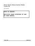
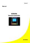
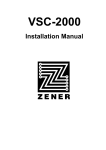
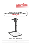
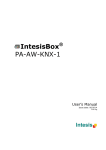
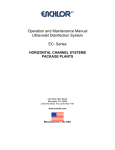
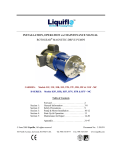
LiquiFlo AC Drives
Introduction
A Compact, Liquid-Cooled
Variable Speed Drive for High
Horsepower Applications
The Reliance Electric LiquiFlo™ AC drive combines high-performance
variable speed drive technology with a patented liquid-cooling design
in a compact, stand-alone solution for high-horsepower applications
in even the most demanding environments.
AC Drives
PRODUCT BENEFITS
LiquiFlo drives can be used in any high
horsepower (350 - 1000 HP at 460 VAC)
applications where mounting space is at a
premium and a cooling liquid is available.
Primary application examples include:
• compressors
• extruders
• water/WWTP pumping
• petrochemicals
• power generation
• mining
• large chilled water pumps
• pelletizers
• electric vehicles
• pulp and paper
Variable Speed Control for Maximum
Efficiency
Variable Speed Control with No Penalty
in Cost or Size
Variable speed control means varying motor
speed to match load requirements. Here are
a few of the many demonstrated advantages
of variable speed control over fixed speed
control in high horsepower applications:
Traditional fixed-speed motor starters and
reduced voltage starters no longer have a
size or cost advantage over variable speed
control. LiquiFlo drives have a smaller
footprint than both types of starters, as well
as conventionally-cooled AC and DC drives.
In fact, LiquiFlo drives have the industry’s
smallest HP/square inch footprint—60%
smaller compared to air-cooled drives.
Proven Control Technology Paired with
Leading-Edge Cooling Design
The core of a LiquiFlo drive is the power
section and regulator board of the flagship
Reliance Electric GV3000/SE drive. The
GV3000/SE drive power section and regulator
were designed onto the patented LiquiFlo
heatsink to optimize power device ratings
as well as use of material. The GV3000/SE,
a U.S.- designed drive that has sold over
65,000 units since its introduction in 1994, is
a market leader due to its steady evolution in
control schemes and ease of use.
D-99
Product Demonstrators
and Training
The LiquiFlo drive is normally sold as a
chassis. It can be mounted in optional NEMA
1, NEMA 12, or NEMA 4X/12 enclosures.
Additional options, such as input fuses,
disconnects, line reactors and controls can
be configured with the LiquiFlo drive to meet
specific application needs.
Options & Accessories
In addition, applications in the
500 - 1000 HP range, traditionally controlled
by costlier medium voltage drives, are ideal for
LiquiFlo drives.
In addition to being as small as or smaller
than most starters installed, LiquiFlo drives
cost little more than a typical reduced
voltage starter, with all the advantages of
variable speed. Installing LiquiFlo drives
means dramatic savings from the first day of
operation.
Digital DC Drives
Challenging environments may have made
it impossible to consider variable speed for
some high horsepower applications in the
past. With over 80% of the heat generated by
LiquiFlo drives dissipated through the cooling
liquid, they can be totally sealed to protect the
sensitive electronics from even the harshest
conditions.
• Reduced energy consumption. Uses only as
much power as your process load requires.
The energy portion of your utility charges
will be reduced because of the improved
efficiency of variable speed control during
times of less than 100% load requirements.
This means a faster payback for installing
variable speed control. (Some utilities
even offer rebates or other incentives for
installing variable speed control.)
• Longer mechanical system life. Variable
speed control brings the motor up to speed
without the high starting current and torque
caused by motor starters. This means less
wear and tear on mechanical parts such as
gears, belts and sheaves.
• Soft starters can reduce wear and tear on
the mechanical system when starting, but
they cannot vary motor speed over the
motor’s full range efficiently the way that
variable speed drives can.
• Fewer mechanical components and less
maintenance required. Variable speed
control means fewer contactors, motor
current transformers, overload relays and
wiring. Fewer components that wear out
means less work to maintain and less cost
to replace.
Analog DC Drives
PRIMARY APPLICATIONS
Liquid Cooling Design Features
Drive Features
LiquiFlo cooling technology is optimized for
heat dissipation for each frame size and varies
from a hermetically sealed aluminum casting
with cooling passageways to a heatsink singlecast around copper tubing. By design, all
major heat producing components, such
as IGBTs and diodes, are mounted within
the LiquiFlo heatsink itself, resulting in an
extremely compact drive package. Virtually
any available liquid which can be pumped
through copper tubing can be used as the
cooling medium. See the pressure, flow and
temperature specifications for acceptable
cooling liquids later in this document.
• Single pipe in and out connection for easy
mounting and maintenance
• Both pipe in and out connections are located
for easy access and protection against
accidental leakage
• Uses standard size 10, SAE 37º flare female
fittings
• 3-Phase, 50/60 Hz, 380 - 460 VAC
• Digital regulator provides three types of
variable speed control:
• V/Hz, closed-loop vector, and sensorless
enhanced vector control
• Overload:
- In vector mode: 150% overload of
continuous amp rating for 5 seconds
- In V/Hz mode: 110% continuous overload
of continuous amp rating with no time limit
• PWM (Pulse-Width-Modulated) output for
smooth AC waveforms
• GBT (insulated Gate Bi-Polar transistors)
power technology
• Full power rating at 2 kHz carrier frequency
• Open chassis model rated for 55ºC operating
temperature, NEMA 1 up to 40ºC
Options & Accessories
Digital DC Drives
Analog DC Drives
AC Drives
Introduction
LiquiFlo AC Drives
Product Demonstrators
and Training
In an enclosure
D-100
• Standard DC bus inductor (choke) for
reduced line harmonics
• Standard 12-pulse input configuration
for line harmonic attenuation (414 - 643
Amp units only), with 6-pulse available via
jumper connections
• Wireless construction for increased
reliability
• Expanded I/O for additional drive logic
control—fault relays, run relays, preset
speeds, and PI control
• RS-232 serial port for connecting to
personal computer using optional CS3000
drive configuration and control software
• Optional network communication boards
LiquiFlo AC Drives
Introduction
LIQUIFLO DRIVE POWER RATINGS
LiquiFlo Ratings
Model Numbers
HP (kW) Rating at 460 V
Overload Capacity
Continuous Amp Rating
at 2 kHz in V/Hz or Vector Mode
V/Hz Mode
Vector Mode
V/Hz
Vector Mode
110% Continuous
150% for 5 sec.
41L4060
414 Amps
350 (229)
350 (229)
455 Amps
621 Amps
50LW4060
500 Amps
400 (230)
400 (230)
550 Amps
750 Amps
64LW4060
643 Amps
500 (295)
500 (295)
707 Amps
964 Amps
120L4060
1200 Amps
1000 (750)
1000 (750)
1320 Amps
1800 Amps
Condition
AC Drives
ENVIRONMENTAL SPECIFICATIONS
Specification
0° to +55°C
Operating Temperature Inside Cabinet (Ambient)
(32° to 131°F)
-40° to 65° C
Storage Temperature (Ambient)
(-40° to +149° F)
Humidity
5 to 95% (non-condensing)
COOLANT SPECIFICATIONS
Specifications
Inlet Coolant Temperature Range
Model Number 120L4060
15° to 40° C
15° to 40° C
Potable water with approved
corrosion inhibitor
15° to 40° C
(60° to 104° F)
(60° to 104° F)
(60° to 104° F)
7 gpm
5 gpm
8 gpm
3 psi
34 psi
5 psi
450 psi
450 psi
50 psi
16,000 BTU/hour
25,000 BTU/hour
40,000 BTU/hour
Clean water with no additives
Minimum Coolant Flow Rate at Full Load
Differential Coolant Pressure at Minimum Flow Rate
Maximum Inlet Pressure
Maximum Heat Load
Model Numbers
50LW4060 and 64LW4060
Clean water with no additives
Analog DC Drives
Coolant Type
Model Number 41L4060
Refer to D-110 and D-111 for cooling loop opions and pricing
Digital DC Drives
REQUIREMENTS FOR TYPICAL USER-SUPPLIED CIRCULATING LOOP WATER SYSTEM
Options & Accessories
Product Demonstrators
and Training
1. Strainer used to capture contaminants, if required due to water source.
2. Optional flow switch used to protect against water loop failure. Could be wired into function loss input at drive.
3. Optional thermal expansion valve used to control flow based on heatsink temperature.
D-101
Introduction
LiquiFlo AC Drives
DRIVE DIMENSIONS
Model Number
41L4060
50LW4060
64LW4060
120L4060
Dim. A
Dim. B
Dim. C
Dim. D
Dim. E
Dim. F
Dim. G
18.69
31.52
14.06
15.63
28
1.53
0.79
275
(475)
(800)
(357)
(397)
(711)
(39)
(20)
(125)
22.96
38.23
13.66
18.25
31
1.09
1
370
(583)
(971)
(347)
(464)
(787)
(28)
(25)
(168)
22.96
38.23
13.66
18.25
31
1.09
1
375
(583)
(971)
(347)
(464)
(787)
(28)
(25)
(170)
39.75
49
14.16
33
47.25
1.09
1
850
(1010)
(1245)
(360)
(838)
(1200)
(28)
(25)
(385)
pounds (kg)
Analog DC Drives
AC Drives
inches (mm)
Model Numbers
Digital DC Drives
41L4060
50LW4060
64LW4060
Model Numbers
Product Demonstrators
and Training
Options & Accessories
120L4060
D-102
Weight
LiquiFlo AC Drives
Continuous Amp Rating at 2 kHz
Drive Model Number
List(1)
414 Amps
41L4060
$23,650
500 Amps
50LW4060
36,850
643 Amps
64LW4060
42,240
1200 Amps
120L4060
67,320
Introduction
PRICING
(1) Contact your nearest Regional Drive Center for order entry and availability.
PANEL MOUNTING KITS
Drive Model Number
Panel Mounting Kit Model Number
List(1)
41L4060
41L4060PM
$1,156
50LW4060
64L4060PM
1,240
64LW4060
64L4060PM
1,240
120L4060
120L4060PM
1,348
Analog DC Drives
• Stocked kits
• Available for field installation only
AC Drives
included in kits 41L4060PM and 120L4060PM. The fan is included
with the drive). (The 64L4060PM dies not include inlet and outlet tube
assemblies.)
Use these kits to mount the LiquiFlo chassis drive in an enclosure.
These kits include inlet and outlet extension hoses, cabling lugs for
power connections, 6-pulse busbar jumpers and a DC bus inductor
cooling fan with brackets (The DC bus inductor cooling fan is not
(1) Contact your nearest Regional Drive Center for order entry and availability.
INSTRUCTION MANUALS
Digital DC Drives
Software: D2-3410
Hardware: D2-3411
Panel Mount Kit for Model Number 41L4060: D2-3460
Panel Mount Kits for Model Numbers 50LW4060 and 64LW4060: D2-3449
Panel Mount Kit for Model Number 120L4060: D2-3467
Options & Accessories
D-103
Product Demonstrators
and Training
DISCOUNT: VS-1AC
AC Drives
Introduction
LiquiFlo 2.0 AC Drives
A Compact High Horsepower VS AC Drive:
Designed For Fan/Pump Applications
• Liquid Cooled
• Cost Effective
• Fully Regenerative
• IEEE519 & CE Harmonic Limit Compliant
• Voltage Flexible
Analog DC Drives
The Reliance Electric LiquiFlo™ 2.0 AC drive is a PWM (Pulse-Width-Modulated),
liquid-cooled drive that provides Sensorless vector and general purpose
Volts-per-Hertz regulation for high-horsepower applications.
IEEE 519 – Line Harmonics
APPLICATION DATA
OPTIONS
The LiquiFlo 2.0 AC drive features an activerectifier with input filter allowing the drive to
meet IEEE519 standards and CE standards for
Europe for line harmonics.
• Pulse width modulated (PWM): sensorless
vector control V/Hz operation
• AC Line Voltage Variation: -10% to +10%
• Displacement Power Factor: +/- 0.99
• Line Frequency: 50/60 Hz (+/- 2 Hz)
• Motor Lead Lengths: 76 meters (250 feet)
total
• Carrier Frequency: 2 kHz Standard
(software-selectable)
• Current Limit Adjustment: 25% to 150%
of drive rated amps for model numbers
180264-A03, 180264-A06, 180580-A07
• Current Limit Adjustment: 25% to 100%
of drive rated amps for model numbers
180580-A09
•
•
•
•
Digital DC Drives
Full Line Regeneration Capability
Full line regeneration capability produces a
braking system by applying power back into
the AC line.
Volts/Hertz & Sensorless Vector Control
LIQUIFLO 2.0 TECHNOLOGY
The LiquiFlo 2.0 drive is mounted in a NEMA
1 enclosure. Chiller options and water-towater or water-to-air cooling options can be
configured to meet specific application needs.
Product Demonstrators
and Training
Options & Accessories
LiquiFlo 2.0 drives are built on the Reliance
Electric SP600 AC drive regulator.
D-104
Cooling Loop
Water-to-Water
Water-to-Air
Chiller
LiquiFlo 2.0 AC Drives
Introduction
PRODUCT FEATURES
IEEE 519 – Line Harmonics
Benefits of Synchronous Rectifier front ends:
• Unity and/or Controlled Power Factor:
The input line currents are regulated by
the synchronous rectifier; therefore, a
predetermined power factor can be set by
the controls. This power factor is usually
set to unity to maximize the unit’s current
draw; however, it is possible to dynamically
change the power factor to meet the user’s
desire to have an improved plant power
factor.
Analog DC Drives
Each of these benefits has varying degrees
of importance to a user, but with a good
synchronous rectifier the user always has
the option to avoid issues and improve
performance. With a fix front end, one’s
options are limited and there may be no
solution for some problems that arise in the
field.
AC Drives
• Regenerative Power Flow: IGBT devices will
allow power to flow into or out of the drives.
This is extremely beneficial in that it allows
an AC drive to absorb power from the
application and put it back on the AC line at
relatively the same efficiency level as when
motoring. This one feature allows AC drives
to be used in almost any application, which
was previously solved with a DC drive.
• Full rated Voltage on the Motor for Wide
Input Voltage Ranges: A synchronous
rectifier can regulate the voltage level on
the DC bus. The buck boost nature of the
topology allows voltage levels on the DC
bus to be higher than the peak of the AC
line. During line sags, brownouts and other
low voltage conditions the synchronous
rectifier can maintain the DC bus at its
rated voltage and thus provide full output
voltage to the motor under almost all low
line conditions. One very good example of
this benefit is that the same drive and 480V
motor can be used on a 380 Volt 50Hz line
and a 480V 60Hz line and the motor will
still operate at 480V and provide the same
torque for both cases.
• Harmonics: The current waveforms
produced by a synchronous rectifier are
regulated to be sine waves. Thus, the
current harmonics can be regulated to meet
IEEE519 as well as the current CE standards
for Europe with no additional modifications.
Current harmonics are less than 5% while
Voltage harmonics in the range of 0.5 to 2%
are typical at the drive.
• Bus Over Voltages: Just as critical as it is
to keep the DC bus above an acceptable
voltage level, it is also possible to be too
high. A synchronous rectifier will regulate
the DC bus and lower the voltage if it rises
above the desired set point. Repetitive line
spikes will increase the DC bus voltage
during the spike; however, the synchronous
rectifier will reduce the level as soon as
the spike has passed, thus preventing the
ratcheting up of the DC bus voltage level
with each spike. The LC filter formed by the
rectifier and the DC bus capacitors will also
limit the transient voltage excursions.
Digital DC Drives
Options & Accessories
Product Demonstrators
and Training
D-105
Product Demonstrators
and Training
Options & Accessories
Digital DC Drives
Analog DC Drives
AC Drives
Introduction
LiquiFlo 2.0 AC Drives
DIMENSIONS
180264-A03-600 and 180264-A06-600 Model Numbers
D-106
LiquiFlo 2.0 AC Drives
Introduction
DIMENSIONS
180580-A07-600 and 180580-A09-600 Model Numbers
AC Drives
Analog DC Drives
Digital DC Drives
Options & Accessories
Product Demonstrators
and Training
D-107
Introduction
LiquiFlo 2.0 AC Drives
LiquiFlo 2.0 Drive Power Ratings
Drive Assembly Number
Input Power
(KVA)
Input Voltage
(V)
Input Current
(Amps)
Output Current
at 2 kHz
(Amps)
180264-A03-600
337
460 ± 10%
405
405
180264-A06-600
515
460 ± 10%
608
608
180580-A07-600
673
460 ± 10%
810
810
180580-A09-600*
1010
460 ± 10%
1215
1215
460 VAC Input
AC Drives
No Options
• 110% output current capability for one minute, 150% output current capability for 5 sec. for model numbers 180264-A03, 180264-A06,
180580-A07
• 100% Continuous Capability with no Overload Capability for model number 180580-A09
• Input Voltage Rating (346 - 480 VAC @ 50 or 60 Hz.) with 460 VAC Output. If input voltage lower than 460 VAC is applied, then the continuous
current rating must be lowered by the same percentage as the voltage.
Continuous Current = [(Actual AC Input / 460 VAC) * Input Current Rating.
Environmental Specifications
Condition
Specification
Operating Temperature
0° C to +55° C (1) (32° to 131° F)
Analog DC Drives
(inside NEMA 1 enclosure)
Ambient Temperature
0°C to +40° C (32° to 104° F)
(outside NEMA 1 enclosure)
Storage Temperature (Ambient)
-40°C to +65° C (-40° to 149° F)
Humidity
5% to 95% (non-condensing)
(1) With typical heat rise inside a cabinet, 40° C ambient outside usually results in 55° C inside.
Coolant Specifications and Pricing
Specification
405 Amps
Digital DC Drives
Coolant Type:
608 Amps
810 Amps
1215 Amps
25% Ethylene Glycol (WEG) (% by weight)
Inlet Coolant Temperature Range
5-40° C
5-40° C
5-40° C
5-40° C
Minimum Coolant Flow Rate at Full Load
7 GPM
7 GPM
15 GPM
15 GPM
Maximum Inlet Pressure
Maximum Heat Load
Base Model Number
Req. BTU
Flow GPM @ PSI
Product Demonstrators
and Training
Options & Accessories
Chill Plate Max. PSI
D-108
180 PSI
180 PSI
180 PSI
180 PSI
6000 Watts
9000 Watts
12,000 Watts
18,000 Watts
180624-A03
180264-A06
180580-A07
180580-A09
20,490
7gpm
@ 50psi
180
30,735
7 gpm
@ 50psi
180
40,980
15gpm
@ 50 psi
180
61,470
15 gpm
@ 50 psi
180
LiquiFlo 2.0 AC Drives
Sample Model Number
Base Number
AC Input Voltage Selection
Option Selection
180264-A03-6AA
180264-A03-
6
AA
Introduction
Model Number Configuration Example: 180264-A03-6AA
180264-A03 = LF2 405 Amps; 6 = 460VAC / 60Hz.; AA = 3 Phase Input Meter
Refer to the table below for appropriate Voltage and option codes.
PRICING
Standard Drives - LiquiFlo 2.0 AC Drives: 460 VAC
Base Drive Model Number
180264-A03-***
180264-A06-***
180580-A07-***
180580-A09-***
405
608
810
1215
$41,085
$59,955
$83,622
$98,650
Nema 1 Enclosure
Standard
Standard
Standard
Standard
Door Mounted LCD OIM
Standard
Standard
Standard
Standard
Control Transformer: 460:120 VAC, 3KVA
Standard
Standard
Standard
Standard
65KAIC Circuit Breaker
Standard
Standard
Standard
Standard
IEEE519 & CE Harmonic Limit Compliant
Standard
Standard
Standard
Standard
Input Line Reactor
Standard
Standard
Standard
Standard
Amp Rating
AC Drives
How to Order: Select base model number, voltage and option selections from chart below. Contact your local distributor or fax order to Reliance
Electric at (864) 284-5075. For assistance call Reliance Electric at (864) 297-4800 and request Inside Sales.
Comments
FLA @ 2kHz
Base Drive List
Standard Devices:
460-480VAC, 60Hz.
Replace First * with your voltage selection Option Code Number
Analog DC Drives
Input Voltage Selection:
Option Code:
Standard
Standard
Standard
Standard
“6”
346VAC, 50Hz.
(2)
(2)
(2)
(2)
“8”
380-415VAC, 50Hz.
(2)
(2)
(2)
(2)
“3”
Replace Second & Third * with the two letter Option Code
1. 3PH Input Metering
Option Code:
824
824
824
824
“AA”
800
1600
3200
4800
“BA”
3. CE Touch – LVD
900
900
1000
1000
“CA”
Option 1 + 2
1624
2424
4024
5624
“KA”
Option 1 + 3
1724
1724
1824
1824
“LA”
Option 2 + 3
1700
2400
4200
5800
“TA”
Option 1 + 2 + 3
2524
3324
5024
6624
“ZB”
2. 100KAIC Circuit
Breaker
No Options
Network Communication Module
0
0
0
0
“00”
(1)
(1)
(1)
(1)
Order Separate
Options & Accessories
1 Refer to page D-39 for Network Options and pricing.
Digital DC Drives
Options:
2 No Additional Charge for Optional Input Voltage rating, but it must be specified at order entry.
INSTRUCTION MANUAL
User Manual: D2-3518-1
D-109
Product Demonstrators
and Training
DISCOUNT: VS-1AC
Introduction
LiquiFlo Cooling Loop
LiquiFlo Cooling Loop Specifications/Selection
Req. BTU
Minimum Coolant Flow Rate at Full
Load @ PSI
Chill Plate Max. PSI
41L4060
414 Amps
16,000
50LW4060
500 Amps
25,000
64LW4060
643 Amps
25,000
120L4060
1200 Amps
40,000
7GPM @3 psi
5 GPM @34 psi
5 GPM @34 psi
8 GPM @ 5 psi
180
180
180
50
LF2.0 Base Model Number
180624-A03
405 Amps
LF1.0 Base Model Number
AC Drives
Inner Loop Coolant Type:
Req. BTU
Minimum Coolant Flow Rate at Full
Load @PSI
Chill Plate Max. PSI
Maximum Heat Load
180264-A06
180580-A07
608 Amps
810 Amps
25% Ethylene Glycol (WEG) (% by weight)
180580-A09
1215 Amps
20,490
30,735
40,980
61,470
7 GPM @35PSI
7 GPM @ PSI
15 GPM @ 35PSI
15 GPM @ PSI
180 PSI
180 PSI
180 PSI
180 PSI
6000 Watts
9000 Watts
12,000 Watts
18,000 Watts
Water to Water Heat Exchanger
Inlet Coolant Temperature Range
Max. Ambient
180264-A06-6WW
5-40° C
5-40° C
5-40° C
5-40° C
104 deg. F
104 deg. F
104 deg. F
104 deg. F
YES
YES
Analog DC Drives
180580-A09-6WW
YES - (64LW4060)
YES - (180580-A07)
YES
90 deg. F
90 deg. F
Yes
Yes
104 deg. F
104 deg. F
Yes
Yes
Water to Air Heat Exchanger
Max. Ambient
90 deg. F
180264-A06-6WA
90 deg. F
Yes
180580-A07-6WA
Yes
180580-A09-6WA
Chiller
Max. Ambient
104 deg. F
180264-A03-6CH
104 deg. F
Yes
180264-A06-6CH
Yes
Digital DC Drives
180580-A09-6CH
Cooling Loop Part Number
180580
108264 -
A03
A06
A07 -
6 CH
Base Number
Cooling Loop Type
Options & Accessories
WW = Water to Water
WA = Water to Air
CH = Chilled
Drive Voltage Code
3 = (380 - 415V, 50 Hz)
6 = (440 - 480V, 60 Hz)
Product Demonstrators
and Training
Frame Size
D-110
LiquiFlo Cooling Loop
Introduction
Cooling Loop Pricing
WATER TO WATER
Part Number
List
180264-A06-6WW
$8,617
180264-A06-3WW
8,746
180580-A09-6WW
9,212
180580-A09-3WW
9,350
WATER TO AIR
List
$10,940
180264-A06-3WA
11,159
180580-A07-6WA
11,740
180580-A07-3WA
11,975
180580-A09-6WA
15,260
180580-A09-3WA
15,565
AC Drives
Part Number
180264-A06-6WA
CHILLED
List
$15,030
180264-A03-3CH
15,180
180264-A06-6CH
16,910
180264-A06-3CH
17,079
180580-A09-6CH
20,015
180580-A09-3CH
20,215
Analog DC Drives
Part Number
180264-A03-6CH
ACCESSORIES
Part Number
List
Digital DC Drives
Description
$252
5Gal. PreMix
LF-WW5GAL
5Gal.100% glycol
LF-WW-5GAL-100
352
Hose Kit 10Ft.
LF-WW-HOSE-10
646
Options & Accessories
D-111
Product Demonstrators
and Training
DISCOUNT: VS-1AC