1
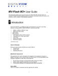
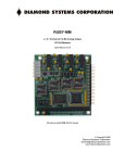
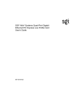
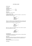
Xtreme I/O Family
User Manual
Connect Tech Inc.
42 Arrow Road
Guelph, Ontario
N1K 1S6
Tel:
Toll:
Fax:
Email:
Web:
519-836-1291
800-426-8979 (North America only)
519-836-4878
[email protected]
[email protected]
www.connecttech.com
CTIM-00059 Revision 0.00 September 16, 2010
Connect Tech Xtreme I/O Family User Manual
Limited Lifetime Warranty
Connect Tech Inc. provides a lifetime warranty for all of our products. Should this product, in
Connect Tech Inc.’s opinion, fail to be in good working order during the warranty period,
Connect Tech Inc. will, at its option, repair or replace this product at no charge, provided that the
product has not been subjected to abuse, misuse, accident, disaster or non Connect Tech Inc.
authorized modification or repair.
You may obtain warranty service by delivering this product to an authorized Connect Tech Inc.
business partner or directly to Connect Tech Inc. along with proof of purchase. Product returned
to Connect Tech Inc. must be pre-authorized by Connect Tech Inc. with an RMA (Return
Material Authorization) number marked on the outside of the package and sent prepaid, insured
and packaged for safe shipment. Connect Tech Inc. will return this product by prepaid ground
shipment service.
The Connect Tech Inc. lifetime warranty is defined as the serviceable life of the product. This is
defined as the period during which all components are available. Should the product prove to be
irreparable, Connect Tech Inc. reserves the right to substitute an equivalent product if available
or to retract lifetime warranty if no replacement is available.
The above warranty is the only warranty authorized by Connect Tech Inc. Under no
circumstances will Connect Tech Inc. be liable in any way for any damages, including any lost
profits, lost savings or other incidental or consequential damages arising out of the use of, or
inability to use, such product.
Copyright Notice
The information contained in this document is subject to change without notice. Connect Tech
Inc. shall not be liable for errors contained herein or for incidental consequential damages in
connection with the furnishing, performance, or use of this material. This document contains
proprietary information that is protected by copyright. All rights are reserved. No part of this
document may be photocopied, reproduced, or translated to another language without the prior
written consent of Connect Tech Inc.
Copyright
2010 by Connect Tech Inc.
Trademark Acknowledgment
Connect Tech Inc. acknowledges all trademarks, registered trademarks and/or copyrights
referred to in this document as the property of their respective owners.
Not listing all possible trademarks or copyright acknowledgments does not constitute a lack of
acknowledgment to the rightful owners of the trademarks and copyrights mentioned in this
document.
2
Revision 0.00
Connect Tech Xtreme I/O Family User Manual
Table of Contents
Limited Lifetime Warranty ............................................................................................................................................... 2
Copyright Notice............................................................................................................................................................... 2
Trademark Acknowledgment ............................................................................................................................................ 2
Table of Contents .............................................................................................................................................................. 3
Revision History ............................................................................................................................................................... 3
Customer Support Overview ............................................................................................................................................. 4
Contact Information .......................................................................................................................................................... 4
Introduction....................................................................................................................................................................... 5
Product Features ............................................................................................................................................................... 5
Board Diagram.................................................................................................................................................................. 6
Block Diagram .................................................................................................................................................................. 7
Digital Outputs.................................................................................................................................................................. 8
Digital Inputs ...................................................................................................................................................................10
PCI-104 Information ........................................................................................................................................................12
LED Indicators.................................................................................................................................................................14
Device Software/Configuration Information....................................................................................................................15
PCI Device Information ...................................................................................................................... 15
Device Register Description ................................................................................................................ 15
Isolated Digital Output Register (DOUT) ........................................................................................16
Isolated Digital Input Register (DIN) ...............................................................................................17
Interrupt Status/Source Register (ISDIN) .........................................................................................18
Interrupt Enable/Disable Register (IEDIN) .....................................................................................19
Interrupt Trigger Mode Register (ITDIN) ........................................................................................20
Interrupt Clear Register (ICDIN) .....................................................................................................21
FPGA Custom Configuration...........................................................................................................................................22
Revision History
Revision
0.00
Date
2010-09-02
Revision 0.00
Author(s)
Change(s)
Patrick Dietrich
3
Connect Tech Xtreme I/O Family User Manual
Customer Support Overview
If you experience difficulties after reading the manual and/or using the product, contact the
Connect Tech Inc. reseller from which you purchased the product. In most cases the reseller can
help you with product installation and difficulties.
In the event that the reseller is unable to resolve your problem, our highly qualified support staff
can assist you. Our support section is available 24 hours a day, 7 days a week on our website at:
www.connecttech.com/sub/support/support.asp. See the contact information section below for
more information on how to contact us directly. Our technical support is always free.
Contact Information
We offer three ways for you to contact us:
Mail/Courier
You may contact us by letter at: Connect Tech Inc.
Technical Support
42 Arrow Road, Guelph, ON
Canada N1K 1S6
Email/Internet
You may contact us through the Internet. Our email and URL addresses on the Internet are:
[email protected]
[email protected]
www.connecttech.com
Note:
Please go to the Download Zone or the Knowledge Database in the Support Center on the
Connect Tech Inc. website for product manuals, installation guides, device driver software and
technical tips. Submit your technical support questions to our customer support engineers via
the Support Center on the Connect Tech Inc. website.
Telephone/Facsimile
Technical Support representatives are ready to answer your call Monday through Friday, from
8:30 a.m. to 5:00 p.m. Eastern Standard Time. Our numbers for calls are:
Telephone:
Telephone:
Facsimile:
4
800-426-8979 (North America only)
519-836-1291 (Live assistance available 8:30 a.m. to 5:00 p.m. EST, Monday to
Friday)
519-836-4878 (online 24 hours)
Revision 0.00
Connect Tech Xtreme I/O Family User Manual
Introduction
Connect Tech’s Xtreme I/O Opto is a 48-bit isolated digital input/output board grouped with 24 optically
isolated inputs and 24 optically isolated outputs. The flexibility of the FPGA technology applied to the
Xtreme I/O Opto enables high functionality integration and customization to meet application
requirements. Fully PCI-104 compliant, Xtreme I/O Opto can be controlled directly from a memory
mapped register set in any operating system. The reliability of the Xtreme I/O Opto, along with the added
protection provided by 2kV isolation ensures optimal performance and protection under extreme
environmental conditions. Xtreme I/O Opto is ideal for embedded technology applications in the military,
aerospace, medical and industrial sectors.
Product Features
Specification
Details
Inputs
24 optically isolated inputs (24-bits)
Wide input voltage range from +0 up to +40V DC
All inputs have independent grounds as well as reverse voltage protection
Selectable interrupt generation on any input signal (change of state, rising
or falling edge)
1.8kOhm current limiting series resistor on each input
Outputs
24 optically isolated outputs (24-bits)
Wide output voltage range from +0 up to +40V DC
All outputs are open collector configuration with common emitter
connections
Individual selectable output voltage levels with a 4.7kOhm pull up
Wide output voltage range from +0 up to +40V DC
Maximum output current: 8mA
Connectors
2x25 (50 position) 0.1” (DIL) Pin Headers
Available in Vertical or Right Angle
Bus
PCI-104 (PC/104-Plus)
Optical Isolation
2 kV RMS
Controller
FPGA Register Controlled Device (No jumpers needed)
Custom logic available upon request
Operating
Temperature
-40 to +85 Degrees Celsius
Dimensions
3.775” x 3.550” (PC/104 Compliant)
Bus
PCI-104 (PC/104-Plus)
ISA (PC/104) connector can be optionally installed as a pass-through
connector
Software
Compatibility
Custom CTI Device Drivers for QNX, Linux, Windows
Device can also be controlled directly from a memory mapped register set
in any operating system
Warranty and
Support
Lifetime Warranty
Free Technical Support
Revision 0.00
5
Connect Tech Xtreme I/O Family User Manual
Board Diagram
6
Revision 0.00
Connect Tech Xtreme I/O Family User Manual
Block Diagram
Revision 0.00
7
Connect Tech Xtreme I/O Family User Manual
Digital Outputs
Connector P4 is located on the right side of the board and uses a 50-pin double row (25x2pin with 2.54mm
pitch) connector. This connector is has right angle headers but can also ship in a vertical header
configuration. There are 24 separate isolated digital outputs which each have a pin to source external
power, and a pin for the actual output itself. All the isolated digital outputs share a common ground. Each
of the output signal is configured in an open collector configuration with a 4.7 kOhm pull-up resistor to a
external output voltage VOUT+. The Xtreme/IO uses Avago’s DC Input Multi-Channel Phototransistor
Optocouplers to perform the optical isolation process.
The Xtreme/IO Opto ships from with these properties electrical properties:
VOUT Properties (Externally Supplied)
VOUT (max) +40Vdc
VOUT(min) +0Vdc
ISO_DOUT Current
8mA typical
Response Time
2μs typical within 0-40Vdc input range
Digital Outputs Circuit Diagram
Custom Output Configuration
If your design requires different electrical properties the 4.7kOhm pull-up resistor can be changed to suit
your needs. Please contact Connect Tech Technical Support ([email protected]) to request a
custom configuration.
8
Revision 0.00
Connect Tech Xtreme I/O Family User Manual
Isolated Digital Outputs Connector Pinout (P4)
Pin Number
1
3
5
7
9
11
13
15
17
19
21
23
25
27
29
31
33
35
37
39
41
43
45
47
49
Description
VOUT1
VOUT2
VOUT3
VOUT4
VOUT5
VOUT6
VOUT7
VOUT8
VOUT9
VOUT10
VOUT11
VOUT12
VOUT13
VOUT14
VOUT15
VOUT16
VOUT17
VOUT18
VOUT19
VOUT20
VOUT21
VOUT22
VOUT23
VOUT24
Shared Isolated Ground
Revision 0.00
Pin Number
2
4
6
8
10
12
14
16
18
20
22
24
26
28
30
32
34
36
38
40
42
44
46
48
50
PIN 1
Description
ISO_DOUT1
ISO_DOUT2
ISO_DOUT3
ISO_DOUT4
ISO_DOUT5
ISO_DOUT6
ISO_DOUT7
ISO_DOUT8
ISO_DOUT9
ISO_DOUT10
ISO_DOUT11
ISO_DOUT12
ISO_DOUT13
ISO_DOUT14
ISO_DOUT15
ISO_DOUT16
ISO_DOUT17
ISO_DOUT18
ISO_DOUT19
ISO_DOUT20
ISO_DOUT21
ISO_DOUT22
ISO_DOUT23
ISO_DOUT24
Shared Isolated Ground
PIN 2
9
Connect Tech Xtreme I/O Family User Manual
Digital Inputs
Connector P3 is located on the left side of the board and uses a 50-pin double row (25x2pin with 2.54mm
pitch) connector. This connector is has right angle headers but can also ship in a vertical header
configuration.
The Xtreme/IO uses Avago’s DC Input Multi-Channel Phototransistor Optocouplers to perform the optical
isolation process. The ISO_DIN+ input pins on the 50 pins connector are connected with 1.8kOhm series
resistor for current limiting and to setup the proper switching level. Connect the signal output of your
device to the ISO_DIN+ pin and the ground of output signal to the ISO_DIN- pin.
The Xtreme/IO Opto ships from with these properties electrical properties:
ON / HIGH State
VIH(max) +40Vdc
VIH(min) +3.3Vdc
OFF / LOW State
VIL(max) +1.8Vdc
VIL(min) +0Vdc
Response Time
2μs typical within 0-40Vdc input range
Input Current Consumption Ratings
@ 5Vdc VIH
2.8mA
@ 12Vdc VIH
6.6mA
@ 24Vdc VIH
13.3mA
@ 30Vdc VIH
16.7mA
@ 40Vdc VIH
22.2mA
Digital Inputs Circuit Diagram
Custom Input Configuration
If your design requires different electrical properties the 1.8kOhm series resistor can be changed to suit
your needs. Please contact Connect Tech Technical Support ([email protected]) to request a
custom configuration.
10
Revision 0.00
Connect Tech Xtreme I/O Family User Manual
Digital Inputs Pinout for Connector P3
PIN 1
Pin Number
1
3
5
7
9
11
13
15
17
19
21
23
25
27
29
31
33
35
37
39
41
43
45
47
49
PIN 2
Revision 0.00
Description
ISO_DIN+1
ISO_DIN+2
ISO_DIN+3
ISO_DIN+4
ISO_DIN+5
ISO_DIN+6
ISO_DIN+7
ISO_DIN+8
ISO_DIN+9
ISO_DIN+10
ISO_DIN+11
ISO_DIN+12
ISO_DIN+13
ISO_DIN+14
ISO_DIN+15
ISO_DIN+16
ISO_DIN+17
ISO_DIN+18
ISO_DIN+19
ISO_DIN+20
ISO_DIN+21
ISO_DIN+22
ISO_DIN+23
ISO_DIN+24
No Connect
Pin Number
2
4
6
8
10
12
14
16
18
20
22
24
26
28
30
32
34
36
38
40
42
44
46
48
50
Description
ISO_DIN-1
ISO_DIN-2
ISO_DIN-3
ISO_DIN-4
ISO_DIN-5
ISO_DIN-6
ISO_DIN-7
ISO_DIN-8
ISO_DIN-9
ISO_DIN-10
ISO_DIN-11
ISO_DIN-12
ISO_DIN-13
ISO_DIN-14
ISO_DIN-15
ISO_DIN-16
ISO_DIN-17
ISO_DIN-18
ISO_DIN-19
ISO_DIN-20
ISO_DIN-21
ISO_DIN-22
ISO_DIN-23
ISO_DIN-24
No Connect
11
Connect Tech Xtreme I/O Family User Manual
PCI-104 Information
PCI-104 Connector Pinout (P6)
Connector P6 is connects to the PCI-104 bus, a full listing of the pinout of the connector is found in the
table below.
12
Revision 0.00
Connect Tech Xtreme I/O Family User Manual
PCI-104 Stack Position Selection
The following PCI signals, (INTA#, INTB# INTC# INTD#), (CLK0, CLK1,CLK2, CLK3), (IDSEL0,
IDSEL1, IDSEL2, IDSEL3), are selected by using the jumper block or rotary switch (optionally installed)
on the Xtreme/IO Opto board (J1 / RSW1). Selections need to match the stack location of the Xtreme/IO
Opto in your PCI-104 stack. See the table below for more details.
Stack Location
Revision 0.00
Rotary
Switch
Setting
Jumper
Block
Setting
PCI INT#
PCI CLK
PCI IDSEL
INTA#
CLK0
IDSEL0
INTB#
CLK1
IDSEL1
INTC#
CLK2
IDSEL2
INTD#
CLK3
IDSEL3
13
Connect Tech Xtreme I/O Family User Manual
LED Indicators
The Xtreme/IO Opto has 3 indicator LEDs as shown below. LED D1 will quickly pulse whenever it
detects a change in value to any of the ISO_DIN pins. LED D2 will quickly pulse whenever there is a
change in value to any of the ISO_DOUT pins. LED D3 is the “heartbeat” indicator, the LED should flash
on and off continuously to indicate the Xtreme/IO is operating properly.
D1 – Input Change
D2 – Output Change
D3 – Xtreme/IO “Heartbeat”
If LED D3 is not flashing at all times when the Xtreme/IO is powered up please contact Connect Tech Technical
Support ([email protected]).
14
Revision 0.00
Connect Tech Xtreme I/O Family User Manual
Device Software/Configuration Information
PCI Device Information
The Xtreme/IO product will have the following properties in a PCI system.
PCI Vendor ID:
PCI Device ID:
PCI Class Code:
0x12C4
0x1200
0x0780
The Xtreme/IO has a register bank which is located in the devices BAR 0 location.
Below is the output from the lspci utility in Linux:
00:0b.0 Communication controller [0780]: Connect Tech Inc Device [12c4:1200]
Control: I/O- Mem+ BusMaster- SpecCycle- MemWINV- VGASnoop- ParErr- SteppingSERR- FastB2B- DisINTxStatus: Cap+ 66MHz- UDF- FastB2B- ParErr- DEVSEL=slow >TAbort- <TAbort- <MAbort>SERR- <PERR- INTxInterrupt: pin A routed to IRQ 10
Region 0: Memory at d4000000 (32-bit, non-prefetchable) [size=8K]
Device Register Description
All of the Xtreme/IO register control set is will be memory mapped into BAR0 of the PCI device.
There are six 32-bit registers which control and show the status of the Xtreme/IO board. Each of these
registers bits corresponds to a bit on the digital input (or output) connectors. IE. bit 0 corresponds to
Digital I/O signal 0 and bit 23 corresponds to digital I/O signal 23. The uppers bits of each register
bits 24 to 31 have no effect on the device, so they can be ignored.
Register Map Overview
Register Decription
ISOLATED DIGITAL OUTPUT
ISOLATED DIGITAL INPUT
INTERRUPT STATUS/SOURCE
INTERRUPT ENABLE/DISABLE
INTERRUPT TRIGGER MODE
INTERRUPT CLEAR
Register Name
DOUT
DIN
ISDIN
IEDIN
ITDIN
ICDIN
Read / Write Function
R/W
R
R
R/W
R/W
R/W
Base Addr + Offset (Hex)
0x00
0x04
0x08
0x0C
0x10
0x14
Reg Num
0
1
2
3
4
5
The following pages will give further details and description of each register and how it controls the
Xtreme/IO product.
Revision 0.00
15
Connect Tech Xtreme I/O Family User Manual
Isolated Digital Output Register (DOUT)
General Description: This register is used to directly control the state of the ISO_DOUT pins on
connector P4. Each bit 0-23 of the register directly corresponds to a pin on the connector. This pins
state will follow that of the register. So once a value is set the ISO_DOUT pins will hold that state on
until it is changed again in the DOUT register.
Read / Write Capabilities:
Both Read and Write functions are permitted with this register.
Register Memory Location:
BAR0 BASE + 0x00
Logic Description:
0 = ISO_DOUT Pin will be LOW*
1 = ISO_DOUT Pin will be HIGH*
* the VHL and VLL will depend on what voltage is applied to the corresponding VOUT Pin
Register Layout:
16
Bit
Name
7
DOUT7
6
DOUT6
5
DOUT5
4
DOUT4
3
DOUT3
2
DOUT2
1
DOUT1
0
DOUT0
Bit
Name
15
DOUT15
14
DOUT14
13
DOUT13
12
DOUT12
11
DOUT11
10
DOUT10
9
DOUT9
8
DOUT8
Bit
Name
23
DOUT23
22
DOUT22
21
DOUT21
20
DOUT20
19
DOUT19
18
DOUT18
17
DOUT17
16
DOUT16
Bit
Name
31
-
30
-
29
-
28
-
27
-
26
-
25
-
24
-
Revision 0.00
Connect Tech Xtreme I/O Family User Manual
Isolated Digital Input Register (DIN)
General Description: This register is used to show the state of the ISO_DIN pins on connector P3.
Each bit 0-23 of the register directly corresponds to a pin on the connector. The registers state will
follow that of the input pin.
Read / Write Capabilities:
This register is configured for Read Only functionality.
Register Memory Location:
BAR0 BASE + 0x04
Logic Description:
0 = ISO_DIN Pin is currently in a LOW state
1 = ISO_DIN Pin is currently in a HIGH state
Register Layout:
Bit
Name
7
DIN7
6
DIN6
5
DIN5
4
DIN4
3
DIN3
2
DIN2
1
DIN1
0
DIN0
Bit
Name
15
DIN15
14
DIN14
13
DIN13
12
DIN12
11
DIN11
10
DIN10
9
DIN9
8
DIN8
Bit
Name
23
DIN23
22
DIN22
21
DIN21
20
DIN20
19
DIN19
18
DIN18
17
DIN17
16
DIN16
Bit
Name
31
-
30
-
29
-
28
-
27
-
26
-
25
-
24
-
Revision 0.00
17
Connect Tech Xtreme I/O Family User Manual
Interrupt Status/Source Register (ISDIN)
General Description: This register is used to show the state of any active interrupts on the
Xtreme/IO device. Each bit 0-23 of the register directly corresponds to the status of interrupt on a
ISO_DIN pin on the connector. Interrupts can only be generated (i.e. this register will only change
from non-zero) when the Interrupts are enabled from the IEDIN register. When this register is in a
non-zero state, a PCI interrupt will be generated from the Xtreme/IO device. The PCI interrupt will
remain active until all of the interrupts for each ISO_DIN pin are cleared via the ICDIN register.
Read / Write Capabilities:
This register is configured for Read Only functionality.
Register Memory Location:
BAR0 BASE + 0x08
Logic Description:
Register Layout:
Bit
7
Name
ISDIN7
18
0 = Nothing to report, no interrupt has occurred on the ISO_DIN pin
1 = An Interrupt has occurred on the corresponding ISO_DIN pin
6
ISDIN6
5
ISDIN5
4
ISDIN4
3
ISDIN3
2
ISDIN2
1
ISDIN1
0
ISDIN0
Bit
Name
15
ISDIN15
14
ISDIN14
13
ISDIN13
12
ISDIN12
11
ISDIN11
10
ISDIN10
9
ISDIN9
8
ISDIN8
Bit
Name
23
ISDIN23
22
ISDIN22
21
ISDIN21
20
ISDIN20
19
ISDIN19
18
ISDIN18
17
ISDIN17
16
ISDIN16
Bit
Name
31
-
30
-
29
-
28
-
27
-
26
-
25
-
24
-
Revision 0.00
Connect Tech Xtreme I/O Family User Manual
Interrupt Enable/Disable Register (IEDIN)
General Description: This register is used to enable or disable interrupt generation on the ISO_DIN
pins. Each bit 0-23 of the register directly corresponds to the ISO_DIN pin on the connector. This
register allows the user to configure one or many ISO_DIN pins to be able generate an interrupt based
on the interrupt triggering mode set in the ITDIN register.
Read / Write Capabilities:
Both Read and Write functions are permitted with this register.
Register Memory Location:
BAR0 BASE + 0x0C
Logic Description:
0 = Disable interrupt generation from this ISO_DIN pin
1 = Enable interrupt generation from this ISO_DIN pin
Register Layout:
Bit
Name
7
IEDIN7
6
IEDIN6
5
IEDIN5
4
IEDIN4
3
IEDIN3
2
IEDIN2
1
IEDIN1
0
IEDIN0
Bit
Name
15
IEDIN15
14
IEDIN14
13
IEDIN13
12
IEDIN12
11
IEDIN11
10
IEDIN10
9
IEDIN9
8
IEDIN8
Bit
Name
23
IEDIN23
22
IEDIN22
21
IEDIN21
20
IEDIN20
19
IEDIN19
18
IEDIN18
17
IEDIN17
16
IEDIN16
Bit
Name
31
-
30
-
29
-
28
-
27
-
26
-
25
-
24
-
Revision 0.00
19
Connect Tech Xtreme I/O Family User Manual
Interrupt Trigger Mode Register (ITDIN)
General Description: This register is used to choose the interrupt trigger mode for each of the
ISO_DIN pins. Each bit 0-23 of the register directly corresponds to the ISO_DIN pin on the
connector. This register allows the user to configure one or many ISO_DIN pins to trigger an interrupt
on either a rising of falling edge.
Read / Write Capabilities:
Both Read and Write functions are permitted with this register.
Register Memory Location:
BAR0 BASE + 0x10
Logic Description:
0 = Trigger an interrupt on a Rising Edge of this ISO_DIN pin
1 = Trigger an interrupt on a Falling Edge of this ISO_DIN pin
Register Layout:
20
Bit
Name
7
ITDIN7
6
ITDIN6
5
ITDIN5
4
ITDIN4
3
ITDIN3
2
ITDIN2
1
ITDIN1
0
ITDIN0
Bit
Name
15
ITDIN15
14
ITDIN14
13
ITDIN13
12
ITDIN12
11
ITDIN11
10
ITDIN10
9
ITDIN9
8
ITDIN8
Bit
Name
23
ITDIN23
22
ITDIN22
21
ITDIN21
20
ITDIN20
19
ITDIN19
18
ITDIN18
17
ITDIN17
16
ITDIN16
Bit
Name
31
-
30
-
29
-
28
-
27
-
26
-
25
-
24
-
Revision 0.00
Connect Tech Xtreme I/O Family User Manual
Interrupt Clear Register (ICDIN)
General Description: This register is used to clear an interrupt that has been generated from the
ISO_DIN pins. Each bit 0-23 of the register directly corresponds to the ISO_DIN pin on the
connector. The user can clear one or all interrupt bits in the IDSIN register with this ICDIN register.
It should also be noted that the ICDIN bit corresponding to the ISO_DIN pin must be set back to zero
in order for more interrupts to be generated.
Read / Write Capabilities:
Both Read and Write functions are permitted with this register.
Register Memory Location:
BAR0 BASE + 0x14
Logic Description:
0 = Stop clearing interrupts of this ISO_DIN pin
1 = Clear the interrupt of this ISO_DIN pin*
* must be set back to zero to allow for more interrupts to be generated
Register Layout:
Bit
7
Name
ICDIN7
6
ICDIN6
5
ICDIN5
4
ICDIN4
3
ICDIN3
2
ICDIN2
1
ICDIN1
0
ICDIN0
Bit
Name
15
ICDIN15
14
ICDIN14
13
ICDIN13
12
ICDIN12
11
ICDIN11
10
ICDIN10
9
ICDIN9
8
ICDIN8
Bit
Name
23
ICDIN23
22
ICDIN22
21
ICDIN21
20
ICDIN20
19
ICDIN19
18
ICDIN18
17
ICDIN17
16
ICDIN16
Bit
Name
31
-
30
-
29
-
28
-
27
-
26
-
25
-
24
-
Revision 0.00
21
Connect Tech Xtreme I/O Family User Manual
FPGA Custom Configuration
The Xtreme/IO Opto product uses the Actel ProASIC3 A3P125 FPGA its main control and
configuration unit. Xtreme/IO Opto ships from Connect Tech with a full featured design pre-loaded
into the device. This design allows users to communicate to the control and register portion of the
device through the PCI-104 bus. In some situations some customers may find they would like some
extra features added into the device that are custom suited for their application. This is where the
Xtreme/IO Opto’s FPGA custom configuration can be used.
Connect Tech currently offers two solutions for customers looking to implement a custom FPGA
design into the Xtreme/IO Opto.
Option #1 – Using the Xtreme/IO Opto Development Kit
Connect Tech offers a full featured development kit that allows experienced FPGA users to design
their own HDL to configure the Xtreme/IO Opto’s FPGA.
This development kit includes:
- JTAG Programming Cable
- Full VHDL source code for standard reference design
- Actel Libero IDE Software Suite
Option #2 – Using Connect Tech’s Custom Design Services
Connect Tech offers a highly skilled team of engineers with years of experience in custom FPGA
designs who can efficiently implement whatever solution you are looking for. To request the team's
services please send an email to Connect Tech’s sales department ([email protected]) and they
can assist with getting your FPGA project underway.
22
Revision 0.00