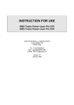
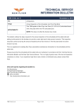
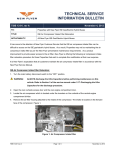
1
RUBY-MM
4 / 8 / 16-Channel 12-Bit Analog Output
PC/104 Modules
User Manual V2.0
(16-channel model RMM-1612-XT shown)
© Copyright 2006
Diamond Systems Corporation
[email protected]
www.diamondsystems.com
TABLE OF CONTENTS
1.
2.
3.
4.
5.
6.
7.
8.
9.
10.
11.
12.
13.
14.
DESCRIPTION .................................................................................................................................................3
BOARD DRAWING..........................................................................................................................................4
I/O HEADER PINOUT.....................................................................................................................................5
BOARD CONFIGURATION ...........................................................................................................................6
ANALOG OUTPUT RANGE CONFIGURATION .......................................................................................7
I/O MAP .............................................................................................................................................................9
REGISTER DEFINITIONS ...........................................................................................................................10
82C55 DIGITAL I/O CHIP OPERATION ...................................................................................................12
ANALOG OUTPUT RANGES AND RESOLUTION .................................................................................13
D/A CODE COMPUTATION ........................................................................................................................14
HOW TO GENERATE AN ANALOG OUTPUT ........................................................................................16
CALIBRATION PROCEDURE ....................................................................................................................18
SPECIFICATIONS .........................................................................................................................................19
82C55 DIGITAL I/O CHIP DATASHEET...................................................................................................20
Copyright 2006 Diamond Systems Corp.
Ruby-MM-412/812/1612 User Manual V2.0 P. 2
RUBY-MM-412/812/1612
16-Channel Analog Output PC/104 Module
1. DESCRIPTION
Ruby-MM-412/812/1612 is a family of PC/104-format data acquisition boards that provide analog outputs
and digital I/O for process control and other applications. Below is a summary of key features:
Analog Outputs
4, 8, or 16 analog voltage outputs with 12-bit resolution (1 part in 4096).
⇒ Note: Analog output, D/A, and DAC are all used interchangeably in this manual.
Multiple Full-Scale Output Ranges
Six different preset ranges are available, including both bipolar and unipolar ranges.
Adjustable Full-Scale Output Range
One of the preset ranges (2.5V full-scale) can be adjusted by the user to any voltage between
approximately 1V and 2.5V.
Simultaneous Update
All analog outputs are updated simultaneously. This prevents time skew errors which can result
from updating outputs sequentially on a system which requires two or more control signals to
change simultaneously.
External Trigger
An external trigger signal can be connected to the board. This trigger can be used to update the
analog outputs. The trigger is enabled in software.
Digital I/O
An 82C55 chip is included to provide 24 lines of digital I/O. Each line has a 10KΩ pull-up resistor.
Each line is CMOS / TTL compatible and can supply up to ±2.5mA of current.
+5V Operation
The board requires only +5VDC from the system power supply for operation. It generates its own
±15V supplies for the analog circuitry on board using four miniature DC/DC converters.
Models:
• RMM-412-XT
• RMM-812-XT
• RMM-1612-XT
4 12-bit analog outputs, 24 digital I/O
8 12-bit analog outputs, 24 digital I/O
16 12-bit analog outputs, 24 digital I/O
Copyright 2006 Diamond Systems Corp.
Ruby-MM-412/812/1612 User Manual V2.0 P. 3
2. BOARD DRAWING
Location
J1:
J2:
J3:
J4:
J5:
J6:
Description
PC/104 8-bit bus connector
PC/104 16-bit bus connector (not used)
User I/O connector
Analog output range configuration jumper block
Base address selection jumper block
ISP header for factory use only; do not connect
Copyright 2006 Diamond Systems Corp.
Ruby-MM-412/812/1612 User Manual V2.0 P. 4
3. I/O HEADER PINOUT
The board provides a 50-pin right-angle connector labeled J3 for all user I/O. This connector is located on
the right side of the board. Pins 1, 2, 49, and 50 are marked to aid in proper orientation. Diamond
Systems’ cable no. C-50-18 or any standard 50-pin cable-mount IDC (insulation displacement contact)
connector will mate with this connector.
J3
(Top of board)
Agnd
Agnd
Agnd
Agnd
Agnd
Agnd
Agnd
Agnd
Vout 8 %
Vout 10 %
Vout 12 %
Vout 14 %
DIO A7
DIO A5
DIO A3
DIO A1
DIO B7
DIO B5
DIO B3
DIO B1
DIO C7
DIO C5
DIO C3
DIO C1
+5V
Signal Name
Vout15 - 0
Agnd
DIO A7-0, B7-0, C7-0
Ext Trig
+5V
Dgnd
1
3
5
7
9
11
13
15
17
19
21
23
25
27
29
31
33
35
37
39
41
43
45
47
49
2
4
6
8
10
12
14
16
18
20
22
24
26
28
30
32
34
36
38
40
42
44
46
48
50
Vout 0
Vout 1
Vout 2
Vout 3
Vout 4 1
Vout 5 *
Vout 6 *
Vout 7 *
Vout 9 %
Vout 11 %
Vout 13 %
Vout 15 %
DIO A6
DIO A4
DIO A2
DIO A0
DIO B6
DIO B4
DIO B2
DIO B0
DIO C6
DIO C4
DIO C2
DIO C0 / Ext Trig
Dgnd
Definition
Analog output channels
* Present on RMM-812-XT and RMM-1612-XT only
% Present on RMM-1612-XT only
Analog ground reference for analog outputs
Digital I/O lines (programmable direction)
Digital I/O line C0 can be used as an external D/A update signal
Connected to PC/104 bus +5V power supply
Digital ground
⇒ Note: The +5V and Dgnd pins do not need to be connected to a power supply to use this board. They
are provided as outputs for convenience purposes only.
Copyright 2006 Diamond Systems Corp.
Ruby-MM-412/812/1612 User Manual V2.0 P. 5
4. BOARD CONFIGURATION
Refer to the board drawing on Page 4 for locations of headers described in Chapters 3 and 4.
Base Address
Each board in the system must have a different base address. Use the pin header labeled J5, base
address. The numbers above the jumpers correspond to the I/O address bits; bit 9 is the MSB and bit 0 is
the LSB. Only bits 9 – 4 are used for the base address decoding. The remaining 4 bits 3-0 are assumed
to be 0 for the base address. When a jumper is in, the corresponding base address bit is a 0, and when it
is out, the bit is a 1.
The default address is 300 Hex = 1 1 0 0 0 0 0 0 0 0, so 9 8 are out and 7 6 5 4 are in. Any address
above 100 Hex is a valid I/O address. However, there are many other circuits and boards sharing the I/O
space, so you should check the documentation for your other boards to avoid conflicts. Below are some
recommended I/O addresses for Ruby-MM. Although the Base addresses can only be selected on 16byte boundaries, Ruby-MM only uses the first 8 addresses.
Table 3.1: Base Address Configuration
Base Address
Hex
220
240
250
260
280
290
2A0
2B0
2C0
2D0
2E0
300
330
340
350
360
380
390
3A0
3C0
3E0
Decimal
544
576
592
608
640
656
672
688
704
720
736
768 (Default)
816
832
848
864
896
912
928
960
992
Copyright 2006 Diamond Systems Corp.
Header J5 Position
9
Out
Out
Out
Out
Out
Out
Out
Out
Out
Out
Out
Out
Out
Out
Out
Out
Out
Out
Out
Out
Out
8
In
In
In
In
In
In
In
In
In
In
In
Out
Out
Out
Out
Out
Out
Out
Out
Out
Out
7
In
In
In
In
Out
Out
Out
Out
Out
Out
Out
In
In
In
In
In
Out
Out
Out
Out
Out
6
In
Out
Out
Out
In
In
In
In
Out
Out
Out
In
In
Out
Out
Out
In
In
In
Out
Out
5
Out
In
In
Out
In
In
Out
Out
In
In
Out
In
Out
In
In
Out
In
In
Out
In
Out
4
In
In
Out
In
In
Out
In
Out
In
Out
In
In
Out
In
Out
In
In
Out
In
In
In
Ruby-MM-412/812/1612 User Manual V2.0 P. 6
5. ANALOG OUTPUT RANGE CONFIGURATION
Refer to the board drawing on Page 4 for locations of headers described in Sections 3 and 4.
Refer to Figure 4.1 on Page for an explanation of the voltage reference circuitry. Also refer to Table 4.1
for a quick guide to output range configuration and jumper settings.
Header J4 is used to configure the analog outputs. Four items are configurable: (1) On-board reference
full-scale voltage, (2) D/A full-scale voltage, (3) unipolar / bipolar select, and (4) adjustable reference
voltage. Items 2 and 3 in turn are configured separately for each bank of 8 analog output channels.
On-Board Reference Full-Scale Voltage Selection
An on-board reference voltage generator provides a +5.000V full-scale voltage output. This voltage is
used as the basis for all on-board full-scale output ranges. This +5 reference drives an operational
amplifier, from which the fixed references are derived. The gain of this amplifier is normally set to 1, so
that its output is also +5.000V. However, you can change the gain to 2 so that the output is +10.00V. For
an output of +5V, install a jumper in location 5 in header J4. For an output of +10V, remove the jumper
from this location. The output of this amplifier is used to generate the full-scale voltages for both bipolar
and unipolar output ranges.
D/A Full-Scale Voltage
The full-scale voltage defines the full output range capability of the analog outputs. Locations F A on
header J4 are used to select the full-scale voltage. Each bank of eight channels has its own selection
pins for full-scale voltage. Thus each bank of eight channels may be configured differently. Install only
one jumper in these locations for each bank of channels. Position F is for the Full-scale voltage (5V or
10V depending on the jumper in position 2, explained above). This is the default setting. Position A is for
the Adjustable reference voltage (see section 4.4).
Unipolar / Bipolar Output Range
Unipolar output ranges are positive voltages only (for example 0 - 5V), while bipolar output ranges include
both positive and negative voltages (for example ±5V). To select unipolar outputs, install a jumper in
position U on J4. to select bipolar outputs, install a jumper in position B. Install only one jumper in these
locations for each bank of channels.
Adjustable Reference Voltage
One full-scale voltage range is adjustable by the user. It is preset to 2.5V (for both 0-2.5V and ±2.5V
ranges), but may be set anywhere between 0V and 2.5V. To adjust this voltage, apply a voltmeter to the
top pin of header J4 underneath either A mark and turn the screw on potentiometer R4 (the fourth from
the left / second from the right in the row of blue potentiometers at the top of the board) until the voltmeter
reads the desired voltage.
Copyright 2006 Diamond Systems Corp.
Ruby-MM-412/812/1612 User Manual V2.0 P. 7
Table 4.1: Analog Output Configuration (Jumper Block J4)
Output Range
0-5V
0-10V
+/-5V
+/-10V
0-2.5V
0-2.5V (alternate configuration)
+/-2.5V
+/-2.5V (alternate configuration)
5
X
X
X
X
F
X
X
X
X
A
B
U
X
X
X
X
X
X
X
X
X
X
X
X
An X means that a jumper is installed in that location. Only one half of pin header J4 is shown.
Positions F A B U are repeated for each bank of 8 channels.
On model RMM-1612-XT, each bank of eight channels (0 - 7 and 8 - 15) can have a different output
range setting. However, all eight channels within a bank will always have the same output range. For the
4 and 8 channel models RMM-412-XT and RMM-812-XT, all channels have the same output range, and
the second set of jumpers has no effect.
Special note for model RMM-812-XT: It is possible to give each group of 4 channels its own output range
by pulling the quad D/A converter chip out of the socket in the U9 location and moving it to the socket in
the U10 location. In this case this chip will take its references from the second set of jumpers, and the
second set of 4 outputs will appear on pins 17-20 on connector J3 (labeled Vout 8-11 in the connector
pinout diagram).
WARNING: This rework should only be attempted by a trained technician with the proper tool to remove
the PLCC from its socket and re-insert it in the new socket. Improper handling of the D/A converter chip
can damage or break its pins or render it inoperative from ESD damage.
Copyright 2006 Diamond Systems Corp.
Ruby-MM-412/812/1612 User Manual V2.0 P. 8
6. I/O MAP
Ruby-MM occupies 8 consecutive 8-bit locations in I/O space. For example, the default base address is
300 Hex (768 Decimal); in this case the board occupies addresses 300 - 307 (768 - 775).
The first 2 locations are used individually for each analog output channel. Since analog output data is 12
bits wide, it is broken into two bytes. The first byte contains the 8 least significant bits (called the LSB) of
the D/A data, and the 4 lowest bits of the second byte contain the 4 most significant bits (called the MSB)
of the D/A data. The 4 highest bits of the second byte are not used.
The DACs are updated all at once when Base or Base+1 is read. The value read from these locations is
not predictable and not meaningful. Only the act of reading from the board is required to perform the
update.
Ruby-MM-1612 I/O Map
Base +
0
1
2
3
4
5
6
7
Write Function
DAC LSB (all DACs)
DAC MSB (all DACs)
DAC channel register
External trigger enable
Digital I/O port A data
Digital I/O port B data
Digital I/O port C data
Digital I/O control register
Read Function
Update all DACs simultaneously
Update all DACs simultaneously
NA
NA
Digital I/O port A data
Digital I/O port B data
Digital I/O port C data
Digital I/O control register
Reset information:
A system hardware reset will also reset the board.
During a reset, the following occurs:
• All analog outputs are set to mid-scale (0V for bipolar ranges and 1/2 full-scale for unipolar
ranges).
• The external trigger register is set to 0, disabling external trigger.
• All digital I/O lines are set to input mode.
The next chapter describes all registers on the board. You should familiarize yourself with these registers
in order to get a complete understanding of the board’s operation.
Copyright 2006 Diamond Systems Corp.
Ruby-MM-412/812/1612 User Manual V2.0 P. 9
7. REGISTER DEFINITIONS
Base + 0, Write: DAC LSB register
Bit No.
7
6
5
4
3
2
1
0
Name
DA7
DA6
DA5
DA4
DA3
DA2
DA1
DA0
DA7-0
D/A data bits 7-0. DA0 is the LSB (least significant bit).
Base + 1, Write: DAC MSB register
Bit No.
7
6
5
4
3
2
1
0
Name
X
X
X
X
DA11
DA10
DA9
DA8
X
Bit not used. These bits will be ignored.
DA11-8
D/A data bits 11-8. DA11 is the MSB (most significant bit).
Base + 0 or 1, Read: Update DACs
Reading from these locations updates all DACs to the values written to them. Only DACs with new data
written to them will change. The remaining channels will retain their current values.
Base + 2, Write: DAC channel register
Bit No.
7
6
5
4
3
2
1
0
Name
X
X
X
X
CH3
CH2
CH1
CH0
X
Bit not used. These bits will be ignored.
CH3-0
D/A Channel no. There are 16 channels numbered 0 to 15.
Copyright 2006 Diamond Systems Corp.
Ruby-MM-412/812/1612 User Manual V2.0 P. 10
Base + 3, Write: External trigger register
Bit No.
7
6
5
4
3
2
1
0
Name
X
X
X
X
X
X
X
TRIGEN
X
Bit not used. These bits will be ignored.
TRIGEN
External trigger enable. 1 = enable, 0 = disable. When external trigger is enabled, digital
I/O line C0 will update all DACs simultaneously when it is brought low. This can be done
either by an external signal, when C0 is in input mode, or in software, when C0 is in
output mode.
If using an external trigger, make sure that the lower half of Port C is in input mode.
Base + 4 through Base + 7
Read/Write
82C55 Digital I/O Registers
These registers map directly to the 82C55 digital I/O chip. The definitions of these registers can be found
in the 82C55 datasheet appended to the back of this manual. A short form description is on the next
page.
These lines power up in input mode. Each line has a 10KΩ pull-up resistor, so on power-up or system
reset, all lines will indicate a logic high.
Copyright 2006 Diamond Systems Corp.
Ruby-MM-412/812/1612 User Manual V2.0 P. 11
8. 82C55 DIGITAL I/O CHIP OPERATION
This is a short form description of the 82C55 digital I/O chip on the board. A full datasheet is included at
the back of this manual.
82C55 Register Map
Base + n, Dir, Function
D7
D6
D5
D4
D3
D2
D1
D0
4, R/W, Port A
A7
A6
A5
A4
A3
A2
A1
A0
5, R/W, Port B
B7
B6
B5
B4
B3
B2
B1
B0
6, R/W, Port C
C7
C6
C5
C4
C3
C2
C1
C0
1
ModeC
ModeA
DirA
DirCH
ModeB
DirB
DirCL
7, W, Config Register
Configuration Register
The configuration register is programmed by writing to Base + 7 using the format below. Once you have
set the port directions with this register, you can read and write to the ports as desired. When you set a
port to output mode, its contents are cleared to 0.
Bit No.
7
6
5
4
3
2
1
0
Name
1
ModeC
ModeA
DirA
DirCH
ModeB
DirB
DirCL
Definitions:
1
Bit 7 must be set to 1 to indicate mode set operation.
DirA
Direction control for bits A7 – A0: 0 = output, 1 = input
DirB
Direction control for bits B7 – B0: 0 = output, 1 = input
DirCL
Direction control for bits C3 – C0: 0 = output, 1 = input
DirCH
Direction control for bits C7 – C4: 0 = output, 1 = input
ModeA, ModeB, ModeC
I/O Mode for each port, 0 or 1
Here is a list of common configuration register values (others are possible):
Configuration Byte
Hex
Decimal
9B
155
92
146
99
153
90
144
8B
139
82
130
89
137
80
128
Copyright 2006 Diamond Systems Corp.
-------------- Direction -------------Port A
Port B
Port C (both halves)
Input
Input
Input
(all ports input)
Input
Input
Output
Input
Output
Input
Input
Output
Output
Output
Input
Input
Output
Input
Output
Output
Output
Input
Output
Output
Output (all ports output)
Ruby-MM-412/812/1612 User Manual V2.0 P. 12
9. ANALOG OUTPUT RANGES AND RESOLUTION
The table below lists the available fixed full-scale output ranges and their corresponding actual full-scale
voltage ranges and resolution.
For any output range, the resolution is equal to the maximum possible range of output voltages divided by
the maximum number of possible steps. For a 12-bit D/A converter as is used on the Ruby-MM, the
12
maximum number of steps is 2 = 4096 (the actual output codes range from 0 to 4095, which is the full
range of possible 12-bit binary numbers). Thus the resolution is equal to 1/4096 times the full-scale
range. This is the smallest possible change in the output and corresponds to a change of 1 in the output
code. Because of this fact the resolution is often referred to as the value of 1 LSB, or 1 least significant
bit.
Table 10.1: Analog Output Ranges and Resolution
Full-Scale
Voltage
10V
5V
2.5V
10V
5V
2.5V
Unipolar
or Bipolar
Unipolar
Unipolar
Unipolar
Bipolar
Bipolar
Bipolar
Range Name
0-10V
0-5V
0-2.5V
±10V
±5V
±2.5V
Negative
Full Scale
0V
0V
0V
-10V
-5V
-2.5V
Positive
Full Scale
+9.9976V
+4.9988V
+2.4994V
+9.9951V
+4.9963V
+2.4988V
Resolution
(1LSB)
2.44mV
1.22mV
0.61mV
4.88mV
2.44mV
1.22mV
In the table above, negative full scale refers to the output voltage for a code of 0, and positive full scale
refers to the output voltage for a code of 4095.
Copyright 2006 Diamond Systems Corp.
Ruby-MM-412/812/1612 User Manual V2.0 P. 13
10. D/A CODE COMPUTATION
Two different methods are used to compute the 12-bit D/A code used for analog output operations.
•
•
For unipolar output ranges (positive voltages only), straight binary coding is used.
For bipolar output ranges (both positive and negative voltages), offset binary coding is used.
For any output range, the resolution is equal to the maximum possible range of output voltages divided by
the maximum number of possible steps. For a 12-bit D/A converter as is used on Ruby-MM, the maximum
12
number of steps is 2 = 4096 (the actual output codes range from 0 to 4095, which is the full range of
possible 12-bit binary numbers). Thus the resolution is equal to 1/4096 times the full-scale range. This is
the smallest possible change in the output and corresponds to a change of 1 in the output code. Because
of this fact the resolution is often referred to as the value of 1 LSB, or 1 least significant bit.
Straight Binary Coding (for unipolar output ranges)
This is the simplest form of binary coding. The output voltage is given by:
Output Voltage = (Output Code / 4096) x Full-Scale Voltage
Example:
Output code = 1024, full-scale voltage = 5V
Output voltage = (1024 / 4096) x 5 = .25 x 5 = 1.250V
Conversely, the output code for a desired output voltage is given by:
Output Code = (Desired Output Voltage / Full-Scale Voltage) x 4096
Example:
Desired output voltage = 0.485V, Full-scale voltage = 2.5V
Output Code = (0.485 / 2.5) x 4096 = 0.194 x 4096 = 795 (rounded up)
The relationship between D/A resolution and Full-scale voltage is:
1 LSB = 1/4096 x Full-Scale Voltage
Example: Full-scale voltage = 5V; 1 LSB = 5V / 4096 = 1.22mV
Here is a brief overview of the relationship between output code and output voltage:
Output Code
0
1
2048
4095
Explanation
0V
1 LSB
1/2 positive full scale
Positive full scale - 1 LSB
Output Voltage for 0-5V Range
0V
.0024V (2.44mV)
2.5V
4.9988V
⇒ Note: In order to generate an output voltage of positive full scale, you would have to output a code of
4096 (4096 / 4096 x full-scale = full-scale). However, 4096 is a 13-bit number which cannot be
reproduced on a 12-bit D/A converter. The highest number that can be output is 4095, which is 4096 - 1.
This results in a maximum output voltage of full scale minus 1 LSB for any analog output range. This
phenomenon is true for all D/A and A/D converters.
Copyright 2006 Diamond Systems Corp.
Ruby-MM-412/812/1612 User Manual V2.0 P. 14
Offset Binary Coding (for bipolar output ranges)
This method takes into account the fact that the lowest output voltage is not zero but a negative value.
The output voltage is given by:
Output Voltage = (Output Code / 2048) x Full-Scale Voltage - Full-Scale Voltage
Example:
Output code = 1024, full-scale voltage = 5V
Output voltage = (1024 / 2048) x 5 - 5 = (0.5 x 5) - 5 = -2.500V
Note the difference between this output voltage to the output voltage using straight binary coding shown
above using the same output code.
Conversely, the output code for a desired output voltage is given by:
Output Code = (Desired Output Voltage / Full-Scale Voltage) x 2048 + 2048
Example:
Desired output voltage = 0.485V, Full-scale voltage = 2.5V
Output Code = (0.485 / 2.5) x 2048 + 2048 = 0.194 x 2048 + 2048 = 2445
(rounded down)
The relationship between D/A resolution and Full-scale voltage is:
1 LSB = 1/2048 x Full-Scale Voltage
Example: Full-scale voltage = 5V; 1 LSB = 5V / 2048 = 2.44mV
The reason that 1 LSB for a bipolar range is twice the magnitude of 1 LSB for a unipolar range with the
same full-scale voltage is that for the bipolar range, the full voltage span is twice the magnitude. For
example, a unipolar range with a full-scale voltage of 5V has a range of 0V to 5V, for a total span of 5V.
However, a bipolar range with a full-scale voltage of 5V has a range of ±5V, for a total span of 10V.
Here is a brief overview of the relationship between output code and output voltage:
Output Code
0
1
2047
2048
2049
4095
Explanation
Negative full scale
Negative full scale + 1 LSB
-1 LSB
0V
+1 LSB
Positive full scale - 1 LSB
Output Voltage for ±5V Range
-5V
-4.9976V
-.0024V (-2.44mV)
0V
+.0024V (+2.44mV)
+4.9976V
⇒ Note: Again, an output code of 4096 would be required to generate the positive-full-scale output
voltage, but since that is impossible, the maximum output voltage is 1 LSB less then positive full scale.
Copyright 2006 Diamond Systems Corp.
Ruby-MM-412/812/1612 User Manual V2.0 P. 15
11. HOW TO GENERATE AN ANALOG OUTPUT
This chapter describes how to generate an analog output directly (without the use of the driver software).
Ruby-MM has 12-bit resolution analog outputs. However, data is written to the board in 8-bit bytes.
Therefore two bytes must be written to the board to generate a single analog output. In addition, many
applications require several channels to be updated simultaneously. In order to provide this ability, the
update operation is separate from the data write operation.
Thus there are three steps required to generate an analog output. Each step is described in detail. The
steps must be completed in the sequence shown below.
To generate an analog output on one or more channels:
1. Write the LSB (least significant byte) to the board at register Base + 0.
2. Write the channel number to the board at register Base + 2..
3. Write the MSB (most significant byte) to the board.
4. Repeat steps 1-3 for each channel to be changed
5. Update all changed channels by reading Base + 0 or Base + 1.
Hardware Update Command
A hardware update command can occur with a falling edge on the external trigger, pin 48 of J3.
To use hardware updating, or triggering, you must program the TRIGEN bit at Base + 3. See Chapter 3
for details.
⇒ Note: When a channel is updated, its output will change only if new data has been written to it since
the last update. For example, if you do a simultaneous update on all channels but you only wrote data to
channel 0, then only channel 0 will change, and channels 1 - 15 will stay the same.
⇒ Note: If hardware updating is enabled, software updating will still work.
Copyright 2006 Diamond Systems Corp.
Ruby-MM-412/812/1612 User Manual V2.0 P. 16
Examples
Single channel output
Assume channels 0 - 7 are configured for 0-5V. To set channel 0 to 3V, do the following:
D/A code is 3V / 5V x 4096 = 2458 (value is rounded to nearest integer)
LSB = 2458 AND 255 = 154
MSB = (2458 AND 3840) / 256 = 9
1. Write 154 to base + 0 (LSB register).
2. Write 0 to base + 2 (Channel register).
3. Write 9 to base + 1 (MSB register). The value 2458 is written to DAC 0.
4. Read from base + 0. DAC 0 now outputs 3.000V.
Two channel output
Assume channels 0 - 7 are configured for 0-5V. To set channel 0 to 3.8V and channel 3 to 1.5V, do the
following:
D/A code for channel 0 = 3.8 / 5 x 4096 = 3113
LSB = 3113 AND 255 = 41
MSB = (3113 AND 3840) / 256 = 12
D/A code for channel 1 = 1.5 / 5 x 4096 = 1229
LSB = 1229 AND 255 = 205
MSB = (1229 AND 3840) / 256 = 4
1. Write 41 to base + 0 (LSB register).
2. Write 0 to base + 2 (Channel register).
3. Write 12 to base + 1 (MSB register). The value 3113 is written to DAC 0.
4. Write 205 to base + 0 (LSB register).
5. Write 0 to base + 2 (Channel register).
6. Write 4 to base + 1 (MSB register). The value 1229 is written to DAC 1.
7. Read from base + 0. DAC 0 and DAC3 are both updated to their new output voltages. All other
channels remain at their existing output voltages.
Copyright 2006 Diamond Systems Corp.
Ruby-MM-412/812/1612 User Manual V2.0 P. 17
12. CALIBRATION PROCEDURE
Calibration requires a voltmeter (at least 5 digits of precision is preferred) and a miniature screwdriver to
turn the potentiometer screws. The common lead of the voltmeter must be connected to analog ground
(not digital ground). The best source for this connection is any of the analog ground pins on the user I/O
header J3.
⇒ Note: All steps should be completed in the sequence shown, since each step affects the following
steps. (Steps 4 and 5 may be interchanged since they do not depend on each other.)
+5.000V Reference Voltage Adjust
Install a jumper in position “5” on J4. Connect the high side lead of the voltmeter to the upper pin of J4
under either location marked “F”. Adjust R1 so that the voltmeter reads +5.000V.
+10.00V Reference Voltage Adjust
Keep the voltmeter connected to as described above. Remove the jumper in position “5” on J4 and
adjust R2 so that the voltmeter reads +10.000V.
Adjustable Reference Adjust
This step can be skipped if you are not using the adjustable reference.
Connect the voltmeter to the upper pin of J4 below either location marked “A” on J4. Adjust R3 so that
the voltmeter reads the desired full-scale voltage range. This voltage is factory-preset to 2.500V. Any
adjustment from about 1V to slightly over 2.5V is achievable.
Negative Full-Scale Reference Adjust, Channels 0 - 7
Install jumpers in positions “5” and the leftmost “F” on J4. Connect the voltmeter to the upper pin on J4
under the leftmost “B”. Adjust R4 so that the voltmeter reads –4.999V. With this setting, the D/A will
actually output closer to –5.000V when it is loaded with all zeros. This value can be adjusted later if
desired by measuring the actual D/A output.
Negative Full-Scale Reference Adjust, Channels 8-15
Install jumpers in positions “5” and the rightmost “F” on J4. Connect the voltmeter to the upper pin on J4
under the rightmost “B”. Adjust R5 so that the voltmeter reads –4.999V.
Copyright 2006 Diamond Systems Corp.
Ruby-MM-412/812/1612 User Manual V2.0 P. 18
13. SPECIFICATIONS
Analog Outputs
No. of outputs
4, 8, or 16 voltage outputs
Resolution
12 bits (1 part in 4096)
Fixed output ranges
0 - 5V, 0 - 10V unipolar, ±5V, ±10V bipolar
Adjustable output range
Preset to 2.5V for 0 - 2.5V, ±2.5V output ranges
Can be adjusted anywhere between approx. 1V and 2.5V
External reference
0V min, 10V max
Settling time
6µs max to ±.01%
Accuracy
±1LSB
Integral nonlinearity
±1LSB max
Differential nonlinearity
-1LSB max, guaranteed monotonic
Output current
±5mA max per channel
Minimum output load
2KΩ
Update method
Simultaneous, software command or external trigger
Reset
All DACs reset to mid-scale
(0V for bipolar ranges, 1/2 full-scale for unipolar ranges)
Digital I/O
No. of lines
24
Compatibility
CMOS / TTL
Input voltage
Logic 0:
Logic 1:
-0.5V min, 0.8V max
2.0V min, 5.5V max
Output voltage
Logic 0:
Logic 1:
0.0V min, 0.4V max
3.0V min, Vcc - 0.4V max
Output current
±2.5mA max per line
Pull-up resistor
10KΩ resistor on each I/O line
External trigger
TTL / CMOS compatible, 10KΩ pull-up resistor, active low edge
Reset
All digital output lines are set to 0
Miscellaneous
Power supply (Vcc)
+5VDC ±10%
Current requirement
430mA, all outputs unloaded (RMM-1612-XT)
Operating temperature
-40 to +85oC
Operating humidity
5 to 95% non-condensing
Size
3.55” x 3.775”
Data bus
8 bits
Copyright 2006 Diamond Systems Corp.
(16-bit header can be installed for
pass-through function but is not used on board)
Ruby-MM-412/812/1612 User Manual V2.0 P. 19
82C55A
CMOS Programmable
Peripheral Interface
June 1998
Features
Description
• Pin Compatible with NMOS 8255A
The Intersil 82C55A is a high performance CMOS version of
the industry standard 8255A and is manufactured using a
self-aligned silicon gate CMOS process (Scaled SAJI IV). It
is a general purpose programmable I/O device which may be
used with many different microprocessors. There are 24 I/O
pins which may be individually programmed in 2 groups of
12 and used in 3 major modes of operation. The high
performance and industry standard configuration of the
82C55A make it compatible with the 80C86, 80C88 and
other microprocessors.
• 24 Programmable I/O Pins
• Fully TTL Compatible
• High Speed, No “Wait State” Operation with 5MHz and
8MHz 80C86 and 80C88
• Direct Bit Set/Reset Capability
• Enhanced Control Word Read Capability
• L7 Process
Static CMOS circuit design insures low operating power. TTL
compatibility over the full military temperature range and bus
hold circuitry eliminate the need for pull-up resistors. The
Intersil advanced SAJI process results in performance equal
to or greater than existing functionally equivalent products at
a fraction of the power.
• 2.5mA Drive Capability on All I/O Ports
• Low Standby Power (ICCSB) . . . . . . . . . . . . . . . . .10µA
Ordering Information
PART NUMBERS
5MHz
8MHz
CP82C55A-5
CP82C55A
IP82C55A-5
IP82C55A
CS82C55A-5
CS82C55A
IS82C55A-5
IS82C55A
CD82C55A-5
CD82C55A
ID82C55A-5
ID82C55A
PACKAGE
40 Ld PDIP
44 Ld PLCC
MD82C55A-5/B MD82C55A/B
8406601QA
8406602QA
40 Ld
CERDIP
8406602XA
PKG.
NO.
0oC to 70oC
E40.6
-40oC to 85oC
E40.6
0oC to 70oC
N44.65
-40oC to 85oC
N44.65
0oC to 70oC
F40.6
-40oC to 85oC
F40.6
-55oC to 125oC
F40.6
SMD#
44 Pad
MR82C55A-5/B MR82C55A/B
CLCC
8406601XA
TEMPERATURE
RANGE
F40.6
-55oC to 125oC
J44.A
SMD#
J44.A
Pinouts
RD
PA0
PA1
PA2
PA3
NC
PA4
PA5
PA6
PA7
WR
34 D3
33 D4
32 D5
31 D6
30 D7
29 NC
CAUTION: These devices are sensitive to electrostatic discharge; follow proper IC Handling Procedures.
http://www.intersil.com or 407-727-9207 | Copyright © Intersil Corporation 1999
1
7
8
9
10
11
12
13
14
15
16
17
39
38
37
36
35
34
33
32
31
30
29
RESET
D0
D1
D2
D3
NC
D4
D5
D6
D7
VCC
18 1920 21 22 23 24 25 26 27 28
PB2
NC
PB3
PB4
PB5
PB6
PB7
37 D0
36 D1
35 D2
6 5 4 3 2 1 44 43 42 41 40
CS
GND
A1
A0
PC7
NC
PC6
PC5
PC4
PC0
PC1
PC2
PC3
PB0
PB1
PA7
PA6
PA5
PA4
PA3
PA2
PA1
PA0
CS
WR
39 NC
38 RESET
NC
VCC
PB7
PB6
PB5
PB4
PB3
PB2
13
14
15
16
17
18
19
20
31
30
29
28
27
26
25
24
23
22
21
82C55A (PLCC)
TOP VIEW
PA4
6 5 4 3 2 1 44 43 42 41 40
PA5
PA6
7
GND
PA7
NC 8
WR
A1 9
RESET
A0 10
D0
PC7 11
D1
PC6 12
D2
PC5 13
D3
PC4 14
D4
PC0 15
D5
PC1 16
D6
PC2 17
D7
18 19 20 21 22 23 24 25 26 27 28
VCC
PB7
PB6
PB5
PB4
PB3
PB1
5
6
7
8
9
10
11
12
40
39
38
37
36
35
34
33
32
PB0
1
2
3
4
PC3
PA3
PA2
PA1
PA0
RD
CS
GND
A1
A0
PC7
PC6
PC5
PC4
PC0
PC1
PC2
PC3
PB0
PB1
PB2
82C55A (CLCC)
TOP VIEW
RD
82C55A (DIP)
TOP VIEW
File Number
2969.2
82C55A
Pin Description
SYMBOL
PIN
NUMBER
VCC
26
VCC: The +5V power supply pin. A 0.1µF capacitor between pins 26 and 7 is
recommended for decoupling.
GND
7
GROUND
D0-D7
27-34
I/O
RESET
35
I
RESET: A high on this input clears the control register and all ports (A, B, C) are set
to the input mode with the “Bus Hold” circuitry turned on.
CS
6
I
CHIP SELECT: Chip select is an active low input used to enable the 82C55A onto the
Data Bus for CPU communications.
RD
5
I
READ: Read is an active low input control signal used by the CPU to read status
information or data via the data bus.
WR
36
I
WRITE: Write is an active low input control signal used by the CPU to load control
words and data into the 82C55A.
A0-A1
8, 9
I
ADDRESS: These input signals, in conjunction with the RD and WR inputs, control
the selection of one of the three ports or the control word register. A0 and A1 are
normally connected to the least significant bits of the Address Bus A0, A1.
PA0-PA7
1-4, 37-40
I/O
PORT A: 8-bit input and output port. Both bus hold high and bus hold low circuitry are
present on this port.
PB0-PB7
18-25
I/O
PORT B: 8-bit input and output port. Bus hold high circuitry is present on this port.
PC0-PC7
10-17
I/O
PORT C: 8-bit input and output port. Bus hold circuitry is present on this port.
TYPE
DESCRIPTION
DATA BUS: The Data Bus lines are bidirectional three-state pins connected to the
system data bus.
Functional Diagram
POWER
SUPPLIES
+5V
GND
GROUP A
PORT A
(8)
GROUP A
CONTROL
GROUP A
PORT C
UPPER
(4)
BI-DIRECTIONAL
DATA BUS
D7-D0
DATA BUS
BUFFER
8-BIT
INTERNAL
DATA BUS
RD
WR
A1
READ
WRITE
CONTROL
LOGIC
GROUP B
CONTROL
GROUP B
PORT C
LOWER
(4)
GROUP B
PORT B
(8)
A0
RESET
CS
2
I/O
PA7-PA0
I/O
PC7-PC4
I/O
PC3-PC0
I/O
PB7-PB0
82C55A
Functional Description
POWER
SUPPLIES
Data Bus Buffer
This three-state bi-directional 8-bit buffer is used to interface
the 82C55A to the system data bus. Data is transmitted or
received by the buffer upon execution of input or output
instructions by the CPU. Control words and status information are also transferred through the data bus buffer.
+5V
GND
BI-DIRECTIONAL
DATA BUS
DATA
BUS
D7-D0
BUFFER
Read/Write and Control Logic
The function of this block is to manage all of the internal and
external transfers of both Data and Control or Status words.
It accepts inputs from the CPU Address and Control busses
and in turn, issues commands to both of the Control Groups.
RD
WR
A1
A0
RESET
READ
WRITE
CONTROL
LOGIC
GROUP A
CONTROL
GROUP A
PORT A
(8)
GROUP A
PORT C
UPPER
(4)
8-BIT
INTERNAL
DATA BUS
GROUP B
CONTROL
GROUP B
PORT C
LOWER
(4)
GROUP B
PORT B
(8)
I/O
PA7PA0
I/O
PC7PC4
I/O
PC3PC0
I/O
PB7PB0
(CS) Chip Select. A “low” on this input pin enables the
communcation between the 82C55A and the CPU.
CS
(RD) Read. A “low” on this input pin enables 82C55A to send
the data or status information to the CPU on the data bus. In
essence, it allows the CPU to “read from” the 82C55A.
FIGURE 1. 82C55A BLOCK DIAGRAM. DATA BUS BUFFER,
READ/WRITE, GROUP A & B CONTROL LOGIC
FUNCTIONS
(WR) Write. A “low” on this input pin enables the CPU to
write data or control words into the 82C55A.
(RESET) Reset. A “high” on this input initializes the control
register to 9Bh and all ports (A, B, C) are set to the input
mode. “Bus hold” devices internal to the 82C55A will hold
the I/O port inputs to a logic “1” state with a maximum hold
current of 400µA.
(A0 and A1) Port Select 0 and Port Select 1. These input
signals, in conjunction with the RD and WR inputs, control
the selection of one of the three ports or the control word
register. They are normally connected to the least significant
bits of the address bus (A0 and A1).
Group A and Group B Controls
82C55A BASIC OPERATION
A1
A0
RD
WR
CS
0
0
0
1
0
The functional configuration of each port is programmed by
the systems software. In essence, the CPU “outputs” a control word to the 82C55A. The control word contains
information such as “mode”, “bit set”, “bit reset”, etc., that initializes the functional configuration of the 82C55A.
INPUT OPERATION
(READ)
Port A → Data Bus
0
1
0
1
0
Port B → Data Bus
1
0
0
1
0
Port C → Data Bus
1
1
0
1
0
Control Word → Data Bus
Each of the Control blocks (Group A and Group B) accepts
“commands” from the Read/Write Control logic, receives
“control words” from the internal data bus and issues the
proper commands to its associated ports.
Control Group A - Port A and Port C upper (C7 - C4)
Control Group B - Port B and Port C lower (C3 - C0)
OUTPUT OPERATION
(WRITE)
0
0
1
0
0
Data Bus → Port A
0
1
1
0
0
Data Bus → Port B
1
0
1
0
0
Data Bus → Port C
1
1
1
0
0
Data Bus → Control
The control word register can be both written and read as
shown in the “Basic Operation” table. Figure 4 shows the
control word format for both Read and Write operations.
When the control word is read, bit D7 will always be a logic
“1”, as this implies control word mode information.
DISABLE FUNCTION
X
X
X
X
1
Data Bus → Three-State
X
X
1
1
0
Data Bus → Three-State
3
82C55A
register will contain 9Bh. During the execution of the system
program, any of the other modes may be selected using a
single output instruction. This allows a single 82C55A to
service a variety of peripheral devices with a simple software
maintenance routine. Any port programmed as an output
port is initialized to all zeros when the control word is written.
Ports A, B, and C
The 82C55A contains three 8-bit ports (A, B, and C). All can
be configured to a wide variety of functional characteristics
by the system software but each has its own special features
or “personality” to further enhance the power and flexibility of
the 82C55A.
ADDRESS BUS
Port A One 8-bit data output latch/buffer and one 8-bit data
input latch. Both “pull-up” and “pull-down” bus-hold devices
are present on Port A. See Figure 2A.
CONTROL BUS
DATA BUS
Port B One 8-bit data input/output latch/buffer and one 8-bit
data input buffer. See Figure 2B.
Port C One 8-bit data output latch/buffer and one 8-bit data
input buffer (no latch for input). This port can be divided into
two 4-bit ports under the mode control. Each 4-bit port contains a 4-bit latch and it can be used for the control signal
output and status signal inputs in conjunction with ports A
and B. See Figure 2B.
C
B
8
A
I/O
PB7-PB0
INPUT MODE
MODE 1
MODE 2
OUTPUT MODE
VCC
I/O
8
I/O
PA7-PA0
A
I/O
8
CONTROL CONTROL
OR I/O
OR I/O
C
I/O
PA7-PA0
A
BIDIRECTIONAL
I/O
PB7-PB0
P
4
PC7-PC4
PC3-PC0
B
8
FIGURE 2A. PORT A BUS-HOLD CONFIGURATION
I/O
C
PB7-PB0
INTERNAL
DATA OUT
(LATCHED)
4
B
8
EXTERNAL
PORT A PIN
RESET
OR MODE
CHANGE
A0-A1
CS
82C55A
MODE 0
MASTER
RESET
OR MODE
CHANGE
INTERNAL
DATA IN
D7-D0
RD, WR
CONTROL
PA7-PA0
FIGURE 3. BASIC MODE DEFINITIONS AND BUS INTERFACE
CONTROL WORD
INTERNAL
DATA IN
D7 D6 D5 D4 D3 D2 D1 D0
EXTERNAL
PORT B, C
PIN
INTERNAL
DATA OUT
(LATCHED)
GROUP B
PORT C (LOWER)
1 = INPUT
0 = OUTPUT
OUTPUT MODE
PORT B
1 = INPUT
0 = OUTPUT
FIGURE 2B. PORT B AND C BUS-HOLD CONFIGURATION
MODE SELECTION
0 = MODE 0
1 = MODE 1
FIGURE 2. BUS-HOLD CONFIGURATION
Operational Description
GROUP A
Mode Selection
PORT C (UPPER)
1 = INPUT
0 = OUTPUT
There are three basic modes of operation than can be
selected by the system software:
Mode 0 - Basic Input/Output
Mode 1 - Strobed Input/Output
Mode 2 - Bi-directional Bus
PORT A
1 = INPUT
0 = OUTPUT
MODE SELECTION
00 = MODE 0
01 = MODE 1
1X = MODE 2
When the reset input goes “high”, all ports will be set to the
input mode with all 24 port lines held at a logic “one” level by
internal bus hold devices. After the reset is removed, the
82C55A can remain in the input mode with no additional initialization required. This eliminates the need to pullup or pulldown resistors in all-CMOS designs. The control word
MODE SET FLAG
1 = ACTIVE
FIGURE 4. MODE DEFINITION FORMAT
4
82C55A
The modes for Port A and Port B can be separately defined,
while Port C is divided into two portions as required by the
Port A and Port B definitions. All of the output registers,
including the status flip-flops, will be reset whenever the
mode is changed. Modes may be combined so that their
functional definition can be “tailored” to almost any I/O
structure. For instance: Group B can be programmed in
Mode 0 to monitor simple switch closings or display computational results, Group A could be programmed in Mode 1 to
monitor a keyboard or tape reader on an interrupt-driven
basis.
This function allows the programmer to enable or disable a
CPU interrupt by a specific I/O device without affecting any
other device in the interrupt structure.
The mode definitions and possible mode combinations may
seem confusing at first, but after a cursory review of the
complete device operation a simple, logical I/O approach will
surface. The design of the 82C55A has taken into account
things such as efficient PC board layout, control signal definition vs. PC layout and complete functional flexibility to support almost any peripheral device with no external logic.
Such design represents the maximum use of the available
pins.
Operating Modes
INTE Flip-Flop Definition
(BIT-SET)-INTE is SET - Interrupt Enable
(BIT-RESET)-INTE is Reset - Interrupt Disable
NOTE: All Mask flip-flops are automatically reset during mode selection and device Reset.
Mode 0 (Basic Input/Output). This functional configuration
provides simple input and output operations for each of the
three ports. No handshaking is required, data is simply written to or read from a specific port.
Mode 0 Basic Functional Definitions:
• Two 8-bit ports and two 4-bit ports
• Any Port can be input or output
Single Bit Set/Reset Feature (Figure 5)
• Outputs are latched
Any of the eight bits of Port C can be Set or Reset using a
single Output instruction. This feature reduces software
requirements in control-based applications.
• Input are not latched
• 16 different Input/Output configurations possible
When Port C is being used as status/control for Port A or B,
these bits can be set or reset by using the Bit Set/Reset
operation just as if they were output ports.
MODE 0 PORT DEFINITION
A
CONTROL WORD
D7 D6 D5 D4 D3 D2 D1 D0
X
X
X
DON’T
CARE
BIT SET/RESET
1 = SET
0 = RESET
BIT SELECT
0 1 2 3 4
0 1 0 1 0
0 0 1 1 0
0 0 0 0 1
5
1
0
1
6
0
1
1
7
1 B0
1 B1
1 B2
BIT SET/RESET FLAG
0 = ACTIVE
FIGURE 5. BIT SET/RESET FORMAT
Interrupt Control Functions
When the 82C55A is programmed to operate in mode 1 or
mode 2, control signals are provided that can be used as
interrupt request inputs to the CPU. The interrupt request
signals, generated from port C, can be inhibited or enabled
by setting or resetting the associated INTE flip-flop, using the
bit set/reset function of port C.
5
B
GROUP A
PORTC
PORT A (Upper)
GROUP B
#
PORTC
PORT B (Lower)
D4
D3
D1
D0
0
0
0
0
Output
Output
0
Output
Output
0
0
0
1
Output
Output
1
Output
Input
0
0
1
0
Output
Output
2
Input
Output
0
0
1
1
Output
Output
3
Input
Input
0
1
0
0
Output
Input
4
Output
Output
0
1
0
1
Output
Input
5
Output
Input
0
1
1
0
Output
Input
6
Input
Output
0
1
1
1
Output
Input
7
Input
Input
1
0
0
0
Input
Output
8
Output
Output
1
0
0
1
Input
Output
9
Output
Input
1
0
1
0
Input
Output
10
Input
Output
1
0
1
1
Input
Output
11
Input
Input
1
1
0
0
Input
Input
12
Output
Output
1
1
0
1
Input
Input
13
Output
Input
1
1
1
0
Input
Input
14
Input
Output
1
1
1
1
Input
Input
15
Input
Input
82C55A
Mode 0 (Basic Input)
tRR
RD
tIR
tHR
INPUT
tAR
tRA
CS, A1, A0
D7-D0
tRD
tDF
Mode 0 (Basic Output)
tWW
WR
tWD
tDW
D7-D0
tAW
tWA
CS, A1, A0
OUTPUT
tWB
Mode 0 Configurations
CONTROL WORD #0
CONTROL WORD #2
D7 D6 D5 D4 D3 D2 D1 D0
1
0
0
0
0
0
0
D7 D6 D5 D4 D3 D2 D1 D0
0
1
8
A
82C55A
4
4
8
B
0
0
0
0
1
0
82C55A
4
PC7 - PC4
PA7 - PA0
PC7 - PC4
C
D7 - D0
4
PC3 - PC0
8
PB7 - PB0
B
PC3 - PC0
PB7 - PB0
CONTROL WORD #3
0
0
D7 D6 D5 D4 D3 D2 D1 D0
1
1
8
A
82C55A
D7 - D0
0
8
D7 D6 D5 D4 D3 D2 D1 D0
0
0
A
CONTROL WORD #1
1
0
PA7 - PA0
C
D7 - D0
0
4
8
B
0
0
0
0
1
1
8
PA7 - PA0
A
82C55A
4
PC7 - PC4
C
4
0
D7 - D0
4
8
B
6
PC7 - PC4
C
PC3 - PC0
PB7 - PB0
PA7 - PA0
PC3 - PC0
PB7 - PB0
82C55A
Mode 0 Configurations
(Continued)
CONTROL WORD #4
CONTROL WORD #8
D7 D6 D5 D4 D3 D2 D1 D0
1
0
0
0
1
0
0
D7 D6 D5 D4 D3 D2 D1 D0
0
1
8
A
82C55A
4
4
8
B
0
0
1
0
0
82C55A
4
8
8
B
0
1
82C55A
PB7 - PB0
0
0
0
1
82C55A
4
PC7 - PC4
PA7 - PA0
PC7 - PC4
C
D7 - D0
4
PC3 - PC0
8
PB7 - PB0
B
PC3 - PC0
PB7 - PB0
D7 D6 D5 D4 D3 D2 D1 D0
1
4
4
8
B
0
0
1
0
0
1
0
8
PA7 - PA0
A
82C55A
4
PC7 - PC4
PA7 - PA0
PC7 - PC4
C
D7 - D0
4
PC3 - PC0
8
PB7 - PB0
B
CONTROL WORD #7
PC3 - PC0
PB7 - PB0
CONTROL WORD #11
D7 D6 D5 D4 D3 D2 D1 D0
0
1
D7 D6 D5 D4 D3 D2 D1 D0
1
1
8
A
82C55A
D7 - D0
1
8
C
D7 - D0
1
0
A
0
8
0
PC3 - PC0
CONTROL WORD #10
A
0
0
PA7 - PA0
D7 D6 D5 D4 D3 D2 D1 D0
0
4
PB7 - PB0
CONTROL WORD #6
1
PC7 - PC4
C
D7 - D0
PC3 - PC0
1
B
1
4
PA7 - PA0
D7 D6 D5 D4 D3 D2 D1 D0
4
0
0
PC7 - PC4
C
D7 - D0
0
0
82C55A
1
8
0
0
CONTROL WORD #9
A
1
0
8
D7 D6 D5 D4 D3 D2 D1 D0
0
1
A
CONTROL WORD #5
1
0
PA7 - PA0
C
D7 - D0
0
4
8
B
0
1
0
0
1
1
8
PA7 - PA0
A
82C55A
4
PC7 - PC4
C
4
0
D7 - D0
4
8
B
7
PC7 - PC4
C
PC3 - PC0
PB7 - PB0
PA7 - PA0
PC3 - PC0
PB7 - PB0
82C55A
Mode 0 Configurations
(Continued)
CONTROL WORD #12
CONTROL WORD #14
D7 D6 D5 D4 D3 D2 D1 D0
1
0
0
1
1
0
0
D7 D6 D5 D4 D3 D2 D1 D0
0
1
8
A
82C55A
4
4
8
B
0
1
1
1
0
1
0
8
82C55A
PA7 - PA0
4
PC7 - PC4
PC7 - PC4
C
D7 - D0
4
PC3 - PC0
PC3 - PC0
8
PB7 - PB0
PB7 - PB0
B
CONTROL WORD #15
D7 D6 D5 D4 D3 D2 D1 D0
0
1
A
CONTROL WORD #13
1
0
PA7 - PA0
C
D7 - D0
0
0
0
D7 D6 D5 D4 D3 D2 D1 D0
1
1
8
A
82C55A
D7 - D0
4
8
B
0
1
1
0
1
1
8
PA7 - PA0
PA7 - PA0
A
82C55A
4
PC7 - PC4
C
4
0
PC7 - PC4
C
D7 - D0
4
PC3 - PC0
PC3 - PC0
8
PB7 - PB0
PB7 - PB0
B
Operating Modes
MODE 1 (PORT A)
Mode 1 - (Strobed Input/Output). This functional configuration provides a means for transferring I/O data to or from a
specified port in conjunction with strobes or “hand shaking”
signals. In mode 1, port A and port B use the lines on port C
to generate or accept these “hand shaking” signals.
CONTROL WORD
D7 D6 D5 D4 D3 D2 D1 D0
1
0
1
1
1/0
INTE
A
PC6, PC7
1 = INPUT
0 = OUTPUT
Mode 1 Basic Function Definitions:
• Two Groups (Group A and Group B)
• Each group contains one 8-bit port and one 4-bit
control/data port
• The 8-bit data port can be either input or output. Both
inputs and outputs are latched.
• The 4-bit port is used for control and status of the 8-bit
port.
8
PA7-PA0
PC4
STBA
PC5
IBFA
INTRA
PC3
RD
PC6, PC7
2
I/O
MODE 1 (PORT B)
CONTROL WORD
D7 D6 D5 D4 D3 D2 D1 D0
Input Control Signal Definition
1
1
1
PB7-PB0
INTE
B
(Figures 6 and 7)
PC2
8
STBB
PC1
IBFB
PC0
INTRB
STB (Strobe Input)
A “low” on this input loads data into the input latch.
RD
IBF (Input Buffer Full F/F)
FIGURE 6. MODE 1 INPUT
A “high” on this output indicates that the data has been
loaded into the input latch: in essence, and acknowledgment. IBF is set by STB input being low and is reset by the
rising edge of the RD input.
8
82C55A
tST
STB
tSIB
IBF
tSIT
tRIB
INTR
tRIT
RD
tPH
INPUT FROM
PERIPHERAL
tPS
FIGURE 7. MODE 1 (STROBED INPUT)
INTR (Interrupt Request)
INTE A
A “high” on this output can be used to interrupt the CPU
when and input device is requesting service. INTR is set by
the condition: STB is a “one”, IBF is a “one” and INTE is a
“one”. It is reset by the falling edge of RD. This procedure
allows an input device to request service from the CPU by
simply strobing its data into the port.
Controlled by Bit Set/Reset of PC6.
INTE B
Controlled by Bit Set/Reset of PC2.
NOTE:
1. To strobe data into the peripheral device, the user must operate
the strobe line in a hand shaking mode. The user needs to send
OBF to the peripheral device, generates an ACK from the peripheral device and then latch data into the peripheral device on
the rising edge of OBF.
INTE A
Controlled by bit set/reset of PC4.
INTE B
MODE 1 (PORT A)
Controlled by bit set/reset of PC2.
PA7-PA0
CONTROL WORD
D7 D6 D5 D4 D3 D2 D1 D0
Output Control Signal Definition
(Figure 8 and 9)
1
0
1
1
1/0
OBF - Output Buffer Full F/F). The OBF output will go “low”
to indicate that the CPU has written data out to be specified
port. This does not mean valid data is sent out of the part at
this time since OBF can go true before data is available.
Data is guaranteed valid at the rising edge of OBF, (See
Note 1). The OBF F/F will be set by the rising edge of the
WR input and reset by ACK input being low.
PC4, PC5
1 = INPUT
0 = OUTPUT
INTE
A
8
PC7
OBFA
PC6
ACKA
INTRA
PC3
WR
ACK - Acknowledge Input). A “low” on this input informs the
82C55A that the data from Port A or Port B is ready to be
accepted. In essence, a response from the peripheral device
indicating that it is ready to accept data, (See Note 1).
PC4, PC5
2
MODE 1 (PORT B)
PB7-PB0
CONTROL WORD
D7 D6 D5 D4 D3 D2 D1 D0
INTR - (Interrupt Request). A “high” on this output can be
used to interrupt the CPU when an output device has
accepted data transmitted by the CPU. INTR is set when
ACK is a “one”, OBF is a “one” and INTE is a “one”. It is
reset by the falling edge of WR.
1
1
PC1
OBFB
PC2
ACKB
PC0
INTRB
0
INTE
B
WR
FIGURE 8. MODE 1 OUTPUT
9
8
82C55A
tWOB
WR
tAOB
OBF
INTR
tWIT
ACK
tAK
tAIT
OUTPUT
tWB
FIGURE 9. MODE 1 (STROBED OUTPUT)
PA7-PA0
RD
CONTROL WORD
D7 D6 D5 D4 D3 D2 D1 D0
1
0
1
1
1/0
1
8
PC4
STBA
PC5
IIBFA
PC6, PC7
1 = INPUT
0 = OUTPUT
PC6, PC7
PB7, PB0
WR
WR
CONTROL WORD
D7 D6 D5 D4 D3 D2 D1 D0
INTRA
PC3
0
PA7-PA0
2
1
0
1
0
1/0
I/O
OBFB
PC2
PC0
PC7
OBFA
PC6
ACKA
INTRA
PC3
1
PC4, PC5
1 = INPUT
0 = OUTPUT
8
PC1
1
8
PC4, PC5
PB7, PB0
2
I/O
8
PC2
STBB
ACKB
PC1
IBFB
INTRB
PC0
INTRB
RD
PORT A - (STROBED INPUT)
PORT B - (STROBED OUTPUT)
PORT A - (STROBED OUTPUT)
PORT B - (STROBED INPUT)
Combinations of Mode 1: Port A and Port B can be individually defined as input or output in Mode 1 to support a wide variety of strobed I/O
applications.
FIGURE 10. COMBINATIONS OF MODE 1
Operating Modes
Mode 2 (Strobed Bi-Directional Bus I/O)
Output Operations
The functional configuration provides a means for communicating with a peripheral device or structure on a single 8-bit
bus for both transmitting and receiving data (bi-directional
bus I/O). “Hand shaking” signals are provided to maintain
proper bus flow discipline similar to Mode 1. Interrupt generation and enable/disable functions are also available.
OBF - (Output Buffer Full). The OBF output will go “low” to
indicate that the CPU has written data out to port A.
Mode 2 Basic Functional Definitions:
• Used in Group A only
• One 8-bit, bi-directional bus Port (Port A) and a 5-bit
control Port (Port C)
• Both inputs and outputs are latched
• The 5-bit control port (Port C) is used for control and
status for the 8-bit, bi-directional bus port (Port A)
INTE 1 - (The INTE flip-flop associated with OBF). Controlled by bit set/reset of PC4.
ACK - (Acknowledge). A “low” on this input enables the
three-state output buffer of port A to send out the data. Otherwise, the output buffer will be in the high impedance state.
Input Operations
STB - (Strobe Input). A “low” on this input loads data into the
input latch.
IBF - (Input Buffer Full F/F). A “high” on this output indicates
that data has been loaded into the input latch.
Bi-Directional Bus I/O Control Signal Definition
INTE 2 - (The INTE flip-flop associated with IBF). Controlled
by bit set/reset of PC4.
(Figures 11, 12, 13, 14)
INTR - (Interrupt Request). A high on this output can be
used to interrupt the CPU for both input or output operations.
10
82C55A
CONTROL WORD
D7 D6 D5 D4 D3 D2 D1 D0
1
1
INTRA
PC3
1/0 1/0 1/0
PA7-PA0
PC2-PC0
1 = INPUT
0 = OUTPUT
PORT B
1 = INPUT
0 = OUTPUT
8
PC7
OBFA
INTE
1
PC6
ACKA
INTE
2
PC4
STBA
PC5
IBFA
WR
GROUP B MODE
0 = MODE 0
1 = MODE 1
PC2-PC0
RD
FIGURE 11. MODE CONTROL WORD
3
I/O
FIGURE 12. MODE 2
DATA FROM
CPU TO 82C55A
WR
tAOB
OBF
tWOB
INTR
tAK
ACK
tST
STB
tSIB
IBF
tAD
tPS
tKD
PERIPHERAL
BUS
tRIB
tPH
RD
DATA FROM
PERIPHERAL TO 82C55A
DATA FROM
82C55A TO PERIPHERAL
DATA FROM
82C55A TO CPU
NOTE: Any sequence where WR occurs before ACK and STB occurs before RD is permissible. (INTR = IBF • MASK • STB • RD ÷ OBF •
MASK • ACK • WR)
FIGURE 13. MODE 2 (BI-DIRECTIONAL)
11
82C55A
MODE 2 AND MODE 0 (INPUT)
MODE 2 AND MODE 0 (OUTPUT)
PC3
PA7-PA0
1
1
0
1
1/0
PC2-PC0
1 = INPUT
0 = OUTPUT
PA7-PA0
8
OBFA
PC7
CONTROL WORD
D7 D6 D5 D4 D3 D2 D1 D0
PC6
ACKA
PC4
STBA
PC5
IBFA
PC2-PC0
PC3
INTRA
3
CONTROL WORD
D7 D6 D5 D4 D3 D2 D1 D0
1
1
0
ACKA
PC4
STBA
IBFA
PC5
3
I/O
8
WR
MODE 2 AND MODE 1 (INPUT)
PC3
PA7-PA0
CONTROL WORD
D7 D6 D5 D4 D3 D2 D1 D0
0
PA7-PA0
8
OBFA
PC6
ACKA
PC4
STBA
PC5
IBFA
PC1
PC3
INTRA
PC7
PB7-PB0
WR
PC6
PB7, PB0
8
MODE 2 AND MODE 1 (OUTPUT)
RD
OBFA
RD
PB7-PB0
1
8
PC7
PC2-PC0
I/O
WR
1
1/0
PC2-PC0
1 = INPUT
0 = OUTPUT
RD
1
0
INTRA
CONTROL WORD
D7 D6 D5 D4 D3 D2 D1 D0
1
1
1
1
OBFB
PC2
ACKB
PC0
INTRB
RD
WR
FIGURE 14. MODE 2 COMBINATIONS
12
8
PC7
OBFA
PC6
ACKA
PC4
STBA
PC5
IBFA
PB7-PB0
8
INTRA
8
PC2
STBB
PC1
IBFB
PC0
INTRB
82C55A
MODE DEFINITION SUMMARY
MODE 1
MODE 0
MODE 2
IN
OUT
IN
OUT
PA0
PA1
PA2
PA3
PA4
PA5
PA6
PA7
In
In
In
In
In
In
In
In
Out
Out
Out
Out
Out
Out
Out
Out
In
In
In
In
In
In
In
In
Out
Out
Out
Out
Out
Out
Out
Out
PB0
PB1
PB2
PB3
PB4
PB5
PB6
PB7
In
In
In
In
In
In
In
In
Out
Out
Out
Out
Out
Out
Out
Out
In
In
In
In
In
In
In
In
Out
Out
Out
Out
Out
Out
Out
Out
PC0
PC1
PC2
PC3
PC4
PC5
PC6
PC7
In
In
In
In
In
In
In
In
Out
Out
Out
Out
Out
Out
Out
Out
INTRB
IBFB
STBB
INTRA
STBA
IBFA
I/O
I/O
INTRB
OBFB
ACKB
INTRA
I/O
I/O
ACKA
OBFA
Special Mode Combination Considerations
GROUP A ONLY
Mode 0
or Mode 1
Only
I/O
I/O
I/O
INTRA
STBA
IBFA
ACKA
OBFA
INPUT CONFIGURATION
There are several combinations of modes possible. For any
combination, some or all of Port C lines are used for control
or status. The remaining bits are either inputs or outputs as
defined by a “Set Mode” command.
D7
D6
D5
I/O
I/O
IBFA
D4
D3
D2
INTEA INTRA INTEB
GROUP A
During a read of Port C, the state of all the Port C lines,
except the ACK and STB lines, will be placed on the data
bus. In place of the ACK and STB line states, flag status will
appear on the data bus in the PC2, PC4, and PC6 bit
positions as illustrated by Figure 17.
D1
D0
IBFB
INTRB
GROUP B
OUTPUT CONFIGURATION
D7
D6
OBFA INTEA
Through a “Write Port C” command, only the Port C pins
programmed as outputs in a Mode 0 group can be written.
No other pins can be affected by a “Write Port C” command,
nor can the interrupt enable flags be accessed. To write to
any Port C output programmed as an output in Mode 1 group
or to change an interrupt enable flag, the “Set/Reset Port C
Bit” command must be used.
D5
D4
I/O
I/O
D3
D2
D1
D0
INTRA INTEB OBFB INTRB
GROUP A
GROUP B
FIGURE 15. MODE 1 STATUS WORD FORMAT
D7
D6
OBFA INTE1
D5
IBFA
D4
INTE2 INTRA
GROUP A
With a “Set/Reset Port Cea Bit” command, any Port C line
programmed as an output (including IBF and OBF) can be
written, or an interrupt enable flag can be either set or reset.
Port C lines programmed as inputs, including ACK and STB
lines, associated with Port C fare not affected by a
“Set/Reset Port C Bit” command. Writing to the corresponding Port C bit positions of the ACK and STB lines with the
“Set Reset Port C Bit” command will affect the Group A and
Group B interrupt enable flags, as illustrated in Figure 17.
D3
D2
D1
D0
X
X
X
GROUP B
(Defined by Mode 0 or Mode 1 Selection)
FIGURE 16. MODE 2 STATUS WORD FORMAT
Current Drive Capability
Any output on Port A, B or C can sink or source 2.5mA. This
feature allows the 82C55A to directly drive Darlington type
drivers and high-voltage displays that require such sink or
source current.
13
82C55A
Reading Port C Status (Figures 15 and 16)
Applications of the 82C55A
In Mode 0, Port C transfers data to or from the peripheral
device. When the 82C55A is programmed to function in
Modes 1 or 2, Port C generates or accepts “hand shaking”
signals with the peripheral device. Reading the contents of
Port C allows the programmer to test or verify the “status” of
each peripheral device and change the program flow
accordingly.
The 82C55A is a very powerful tool for interfacing peripheral
equipment to the microcomputer system. It represents the
optimum use of available pins and flexible enough to interface almost any I/O device without the need for additional
external logic.
Each peripheral device in a microcomputer system usually
has a “service routine” associated with it. The routine
manages the software interface between the device and the
CPU. The functional definition of the 82C55A is programmed
by the I/O service routine and becomes an extension of the
system software. By examining the I/O devices interface
characteristics for both data transfer and timing, and
matching this information to the examples and tables in the
detailed operational description, a control word can easily be
developed to initialize the 82C55A to exactly “fit” the
application. Figures 18 through 24 present a few examples
of typical applications of the 82C55A.
There is not special instruction to read the status information
from Port C. A normal read operation of Port C is executed to
perform this function.
INTERRUPT
ENABLE FLAG
POSITION
ALTERNATE PORT C
PIN SIGNAL (MODE)
INTE B
PC2
ACKB (Output Mode 1)
or STBB (Input Mode 1)
INTE A2
PC4
STBA (Input Mode 1 or
Mode 2)
INTE A1
PC6
ACKA (Output Mode 1 or
Mode 2)
FIGURE 17. INTERRUPT ENABLE FLAGS IN MODES 1 AND 2
INTERRUPT
REQUEST
PC3
PA0
PA1
PA2
PA3
PA4
PA5
MODE 1 PA6
(OUTPUT)
PA7
PC7
PC6
PC5
PC4
HIGH SPEED
PRINTER
HAMMER
RELAYS
DATA READY
ACK
PAPER FEED
FORWARD/REV.
82C55A
PB0
PB1
PB2
PB3
PB4
MODE 1 PB5
(OUTPUT) PB6
PB7
PC1
PC2
PAPER FEED
FORWARD/REV.
RIBBON
CARRIAGE SEN.
DATA READY
ACK
PC0
INTERRUPT
REQUEST
CONTROL LOGIC
AND DRIVERS
FIGURE 18. PRINTER INTERFACE
14