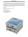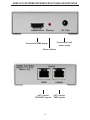
1
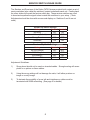
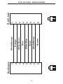
HDMI CAT-5
Extreme
USER
MANUAL
www.gefen.com
ASKING FOR ASSISTANCE
Technical Support:
Telephone
(818) 884-6294
(800) 545-6900
Fax
(818) 884-3108
Technical Support Hours:
9:00 AM to 5:00 PM Monday through Friday.
Write To:
Gefen Inc.
C/O Customer Service
6265 Variel Ave.
Woodland Hills, CA 91367-9897
Notice
Gefen Inc. reserves the right to make changes in the hardware, packaging and any
accompanying documentation without prior written notice.
The HDMI CAT-5 Extreme is a trademark of Gefen Inc.
© 2006 Gefen Inc., All Rights Reserved
TABLE OF CONTENTS
1
Introduction
2
HDMI CAT-5 Extreme Sender Front Panel Descriptions
3
HDMI CAT-5 Extreme Receiver Front Panel Descriptions
4
How To Connect The HDMI CAT-5 Extreme
5
Dip Switch Usage Guide
6
CAT5 Link Cable - Wiring Diagram
7
Mounting Plate Installation
8
Frequently Asked Questions
9
Terminology
10
Specifications
11
Warranty
OPERATION NOTES
READ THESE NOTES BEFORE INSTALLING
OR OPERATING THE HDMI CAT-5 EXTREME EXTENDER
• The HDMI CAT-5 Extreme is housed in a metal box for better RF shielding.
• Your CAT-5 cable should not exceed 200 feet.
• If you do not need DDC or HDCP data you can use a single CAT-5 cable for the video
only. The DDC will not be connected. (For further information, see our Terminology
section on page 9.) If HDCP is required, both CAT-5 cables must be used between the
sender and receiver units.
• If the source requires EDID present, you can use the Gefen DVI Detective to provide
EDID information.
INTRODUCTION
The HDMI CAT-5 Extreme sender unit sits next to your computer, DVD player or any settop box with a HDMI output. The cable supplied with the HDMI CAT-5 Extreme connects
your HDMI source to the send unit. The HDMI CAT-5 Extreme receiver unit sits next to
your HDMI display - up to 200 feet away. The display plugs into the back of the HDMI
CAT-5 Extreme receiver unit. Two CAT-5 cables connect the HDMI CAT-5 Extreme-S and
the HDMI CAT-5 Extreme-R units to each other.
CONTENTS
The HDMI CAT-5 Extreme system consists of:
HDMI CAT-5 Extreme-S
HDMI CAT-5 Extreme-R
1x 6 ft HDMI to HDMI Cable M-M
2x HDMI CAT5 Wallmounts
2x 5V DC power supply
1
HDMI CAT-5 EXTREME SENDER FRONT PANEL DESCRIPTIONS
Connects to 5 volt
power supply
HDMI input connects to
HDMI source
Power Indicator
CAT-5 carries
TMDS signals
CAT-5 carries
DDC/HDCP signals
2
HDMI CAT-5 EXTREME RECEIVER FRONT PANEL DESCRIPTIONS
Connects to 5 volt
power supply
Connects to HDMI display
Power Indicator
CAT-5 carries
DDC/HDCP signals
3
CAT-5 carries
TMDS signals
HOW TO CONNECT THE HDMI CAT-5 EXTREME
1
Connect your display to the HDMI CAT-5 Extreme receiver unit.
2
Connect your source to the HDMI CAT-5 Extreme sender unit
3
Connect your CAT-5 cables between the sender and the receiver
4
Plug the 5V power supply into the HDMI CAT-5 Extreme sender and receiver unit
5
You should now have picture. If you do not see a picture, try unplugging and replugging the HDMI input on the HDMI sender unit. Make sure your CAT-5 cables are
not crossed. Recycle the power on the unit.
* If problems presist try adjusting the Dip Switches by following the Dip Switch
Usage Guide.
4
SERVICE SWITCH USAGE GUIDE
The Senders and Receivers of the Gefen CAT5 Extreme products both contain a set of
service switches (also called dip switches) located underneath each unit. Peeling back
the silver sticker will reveal the service switch bay. These service switches are used
to boost and equalize the signal to best match the conditions in your setup. (*Note:
Adjustments should be done with sources and display on. Switches 3 and 4 are not
used.)
Sender Dip Swich Settings
Setting
Switch 1 Switch 2
No Boost
OFF
ON
Normal Boost (Default)
OFF
OFF
Strong Boost
ON
OFF
Undefined
ON
ON
Receiver Dip Swich Settings
Setting
Switch 1 Switch 2
No EQ (Default)
OFF
OFF
EQ Setting 2
ON
OFF
EQ Setting 3
OFF
ON
Maximum EQ
ON
ON
Adjustment Guidelines:
1)
Strong boost should not be used on stranded cables. Strong boosting will cause
pixels or no picture on these cables.
2)
Using the wrong settings will not damage the units; it will either produce no
image or a noisy image.
3)
To elminate the possibility of cross talk and interference, cables must be
terminated with 568B scheduling. (See page 6 for details)
5
6
1
8
8
7
6
5
4
3
2
1
RJ-45 Jack
Brown
White/Brown
Green
White/Blue
Blue
White/Green
Orange
White/Orange
8
7
6
5
4
3
2
1
1
8
RJ-45 Jack
CAT5 LINK CABLE - WIRING DIAGRAM
MOUNTING PLATE INSTALLATION
7
TROUBLESHOOTING
Frequently Asked Questions
What kind of CAT-5e cable should I be using?
Solid core CAT-5e cable rated at 350 Mhz 568a or 568b is the minimum requirement.
CAT-6 cables are also a viable cable to use.
I’m getting no video on the screens, what can I check?
First thing to check is make sure that the video CAT5 is linked to the other video CAT5
port and the same with the DDC ports. Test to make sure the units are working with short
CAT-5e cables 15-20 feet. Please refer to the Service Switch Usage Guide on page 5.
How can I fix an occasionally flickering or flashing picture?
A flickering or a flashing image is the result of Electromagnetic Interference (EMI). Try a
shielded CAT-5e or CAT-6 cable on the DDC to reduce interference.
Why is there a green or pink tint to my picture?
A tint of green or pink in the picture is a result of incorrect colorspace being transmitted.
This can be resolved by recycling power on your devices including the extender. If this
does not help, the DDC data containing the colorspace is not being transmitted correctly
due to loss in the CAT5 cable, try replacing the DDC cable.
8
TERMINOLOGY
CAT-5
Category 5 cable, commonly known as Cat 5, is an unshielded twisted pair type cable
designed for high signal integrity. The actual standard defines specific electrical properties
of the wire, but it is most commonly known as being rated for its Ethernet capability of 100
Mbit/s. Its specific standard designation is EIA/TIA-568. Cat 5 cable typically has three
twists per inch of each twisted pair of 24 gauge copper wires within the cable.
CAT-5e
Similar to Cat 5 cable, but is enhanced to support speeds of up to 1000 megabits per
second.
DDC
Short form for Display Data Channel. It is a VESA standard for communication between
a monitor and a video adapter. Using DDC, a monitor can inform the video card about its
properties, such as maximum resolution and color depth. The video card can then use
this information to ensure that the user is presented with valid options for configuring the
display.
DDWG
Digital Display Working Group DDWG are the creators of the HDMI specification.
HDMI
The High-Definition Multi-media Interface (HDMI) is an industry-supported, uncompressed,
all-digital audio/video interface. HDMI provides an interface between any compatible digital
audio/video source, such as a set-top box, DVD player, and A/V receiver and a compatible
digital audio and/or video monitor, such as a digital television (DTV).
HDCP
High-Bandwidth Digital Content Protection. Created by Intel, HDCP is used with HDTV
signals over HDMI and HDMI connections and on D-Theater D-VHS recordings to prevent
unauthorized duplication of copy written material.
HDTV
High-Definition Television. The high-resolution subset of our DTV system. The ATSC defines
HDTV as a 16:9 image with twice the horizontal and vertical resolution of our existing system,
accompanied by 5.1 channels of Dolby Digital audio. The CEA defines HDTV as an image
with 720 progressive or 1080 interlaced active (top to bottom) scan lines. 1280:720p and
1920:1080i are typically accepted as high-definition scan rates.
VESA
Video Electronic Standards Association, a consortium of manufacturers formed to establish
and maintain industry wide standards for video cards and monitors. VESA was instrumental
in the introduction of the Super VGA and Extended VGA video graphics standards with
a refresh rate of 70 Hz, minimizing flicker and helping to reduce user eyestrain and
fatigue.
9
SPECIFICATIONS
Video Amplifier Bandwidth ................................................................................ 1.65 Gbps
Input Video Signal ......................................................................................... 1.2 volts p-p
Input DDC Signal .................................................................................... 5 volts p-p (TTL)
Single Link Range .............................................................................1080p / 1920 x 1200
HDMI Connector Type ..................................................................... Type A 19 pin female
Link Connector ........................................................................................................ RJ-45
Power Consumption .................................................................................. 20 watts (max)
Power Supply ......................................................................................................... 5V DC
Dimensions ............................................................................. 3.4” W x 1.25” H x 3.25” D
Shipping Weight ....................................................................................................... 3 lbs.
10
WARRANTY
Gefen Inc. warrants the equipment it manufactures to be free from defects in material
and workmanship.
If equipment fails because of such defects and Gefen Inc. is notified within one (1)
year from the date of shipment, Gefen System will, at its option, repair or replace the
equipment, provided that the equipment has not been subjected to mechanical, electrical
or other abuse or modifications.
Equipment that fails under conditions other than those covered will be repaired at the
current price of parts and labor in effect at the time of repair. Such repairs are warranted
for ninety (90) days from the day of shipment to the Buyer.
This warranty is in lieu of all other warranties expressed or implied, including without
limitation, any implied warranty or merchantability or fitness for any particular purpose, all
of which are expressly disclaimed.
The information in this manual has been carefully checked and is believed to be accurate.
However, Gefen Inc. assumes no responsibility for any inaccuracies that may be contained
in this manual. In no event will Gefen Inc., be liable for direct, indirect, special, incidental,
or consequential damages resulting from any defect or omission in this manual, even if
advised of the possibility of such damages. The technical information contained herein
regarding the HDMI CAT-5 Extreme features and specifications is subject to change without
notice.
11
*ma-HDMI-cat5X*
6265 Variel Avenue Woodland Hills, CA 91367
1-800-545-6900 818-884-6294 fax: 818-884-3108
www.gefen.com
[email protected]