1
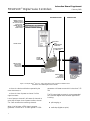
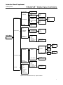
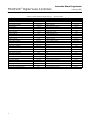
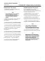
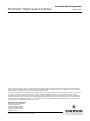
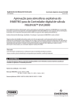
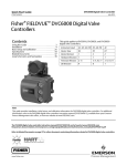
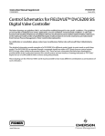
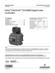
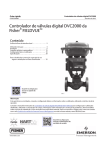
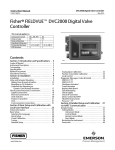
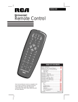
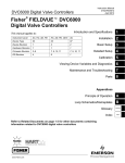
Instruction Manual Supplement
D103267X012
February 2009
FIELDVUE Digital Valve Controllers
Supplement to HARTR Communicating
FisherR FIELDVUER Digital Valve Controller
Instruction Manuals
Using the HARTR Tri-Loopt HART-to-Analog Signal
Converter with FisherR FIELDVUER Digital Valve Controllers
Tri-Loopt Signal Converter
Operation with FIELDVUER Digital
Valve Controllers
The Rosemount 333U (alarm high) and 333D
(alarm low) HART Tri-Loop HART-to-Analog
Signal Converter is used to read values from the
digital valve controller and present them as 4 to 20
mA signals accessible to AI channels on traditional
host systems. This device accepts a HART burst
command 3 from a smart instrument and converts it
into up to three 4 to 20 mA analog output signals.
The output signals then can be read by a control
system’s analog input channels. See table 1 for
command 3 variables.
Figure 1 shows a typical installation of the Tri-Loop
signal converter with a digital valve controller.
Table 1. Command 3 Variables (1)
TYPE
DVC5000
Firmware 5
VARIABLE
VARIABLE NAME
Primary
Travel
Secondary
Travel Target
Tertiary
Pressure
0 to 6.9 bar
0 to 690 kPa
DVC5000
Firmware 6
Quaternary
Auxiliary Status
Primary
Travel
Secondary
Travel Target
Either 0 or 100%
0 to 100%
0 to 100%
0 to 100 psi
Tertiary
Pressure
0 to 6.9 bar
0 to 690 kPa
Quaternary
DVC6000
Drive Signal
0 to 100%
Primary
Analog Input
4−20 mA or 0 to
100% depending on
instrument
configuration
Secondary
Travel Target
0 to 100%
0 to 100 psi
The Tri-Loop signal converter may be used with the
following FIELDVUE digital valve controllers:
DVC6000 Series digital valve controllers, or
0 to 100%
0 to 100 psi
Tertiary
DVC5000 Series digital valve controllers with
firmware revision 5, hardware revision 5 or newer.
(DVC5000 Series digital valve controllers with
firmware revisions earlier than revision 5 do not
support burst mode communications. Instruments
with firmware revision 5 and hardware revision 4 are
not recommended for use with the Tri-Loop signal
converter.)
RANGE
0 to 100%(2)
Quaternary
DVC2000
Pressure (Supply or
Output)(3)
Travel
0 to 6.9 bar
0 to 690 kPa
0 to 100%(2)
Primary
Analog Input
4−20 mA or 0 to
100% depending on
instrument
configuration
Secondary
Travel Target
0 to 100%
Tertiary
Pressure (Output)
0 to 6.9 bar
Quaternary
Travel
0 to 100%
0 to 690 kPa
0 to 100%(2)
1. AC tier does not support HART Command 3 or Burst Mode
communications.
2. 0% valve travel is the zero control signal position for DVC5000
firmware 5, DVC6000, and DVC2000.
3. DVC6000 HC tier does not provide Supply Pressure.
DVC2000 Series digital valve controllers.
The Tri-Loop signal converter outputs will go to their
fail state when any of the following occur:
www.Fisher.com
there is a loss of burst mode communication
from the smart instrument
Instruction Manual Supplement
FIELDVUE Digital Valve Controllers
February 2009
NON-HAZARDOUS AREA
CHANNEL 1 MUST BE
POWERED FOR THE
TRI-LOOP TO OPERATE
EACH TRI-LOOP
CHANNEL RECEIVES
POWER FROM
CONTROL ROOM
HAZARDOUS AREA
VALVE TRAVEL
CHANNEL 2 CONFIGURED OUTPUT (OPTIONAL)
CHANNEL 3 CONFIGURED OUTPUT
(OPTIONAL)
BURST INPUT
HART
COMMUNICATION
CONNECTION
CONTROL ROOM
FIELD INSTRUMENT
CONNECTION
CONTROL
SYSTEM
CONNECTION
−
+
ANALOG OUTPUT
CONTROLLING
DIGITAL VALVE
CONTROLLER
−
+
FISHER HF300 SERIES HART FILTER
USE AN HF340 IF FILTER
ACTION IS REQUIRED. USE AN
HF341 IF NO FILTER ACTION IS
REQUIRED.
INTRINSIC SAFETY
BARRIER
IF REQUIRED
BY APPLICATION
FIELDVUE DIGITAL
VALVE CONTROLLER
IN BURST MODE
(COMMAND 3)
Figure 1. Example HART Tri-Loop HART-to-Analog Signal Converter Installation with a
FIELDVUE DVC6000 Digital Valve Controller
there is a device malfunction reported by the
smart instrument, or
there is a loss of power to channel 1 of the
signal converter.
Loss of power to channel 1 will cause all channels to
go to their fail state. Loss of power to either channel
2 or 3 will not affect the remaining channels.
When in its fail state, a 333U signal converter
generates a current of 21.75 mA or greater. A 333D
2
generates a fail state current which is less than 3.75
mA.
The Tri-Loop signal converter is not recommended
for FIELDVUE digital valve controller applications
involving:
split-ranging, or
multi-drop (digital set point)
Instruction Manual Supplement
FIELDVUE Digital Valve Controllers
February 2009
Table 2. Tri-Loop HART-to-Analog Signal Converter Configuration Choices (1)
CHANNEL(2)
TRI-LOOP MODEL
FAIL STATE
333D
Low
333U
High
1
(Travel)
2
(Travel Target)
3
(Not Configured)
0 to 100%
0 to 100%
Disabled
1. Tri-Loops pre-configured for use with DVC5000 digital valve controllers are configured differently than those pre-configured for use with DVC6000 and
DVC2000 digital valve controllers.
2. Configurations of channels are preset, but can be changed with the 275 HART Communicator, the 375 Field Communicator, or AMS Device Manager.
Installation Considerations
The Tri-Loop HART-to-analog signal converter
design allows three different din-rail mounting
options:
Asymmetrical 32mm G rail
Symmetrical 35 x 7.5 mm top hat rail
Symmetrical 35 x 15 mm top hat rail
As shown in figure 1, the signal converter must be
installed on the safe side of an Intrinsic Safety (IS)
barrier. It is approved for FM and CSA ordinary
location, and bears the CE marking to indicate
compliance with applicable EC directives. It is not
approved nor designed for nuclear-qualified
applications.
Figure 1 also shows a HART filter as a convenient
connection point for the two additional connections
to the loop wires. The necessity of a HART filter
depends upon the control system; the Tri-Loop
signal converter does not add a requirement for a
filter. If a filter is required, the HF340 din rail mount
filter provides a convenient method for connecting
field wiring between the control system, the signal
converter and the digital valve controller. If no filter is
required, the HF341 is available without filter action
(straight-through).
Tri-Loopt Signal Converter
Configuration From Fisher
The Tri-Loop HART-to-analog signal converter ships
from Fisher pre-configured with one of the choices
listed in table 2. As shown in the table the unit is
available with either a high or low fail state. The
channel 1 variable is always travel and the channel 2
variable is always travel target. Channel 3 is
disabled, but can be configured by the user, using
the 275 HART Communicator, the 375 Field
Communicator, or AMS Suite: Intelligent Device
Manager.
The burst message from FIELDVUE digital valve
controllers configured for fail-open actuators
associates 0% travel with an open valve. Therefore,
channel 1 of the Tri-Loop should be configured to
provide a 20 mA output when the valve is open and
a 4 mA output when the valve is closed (range is
100 to 0 rather than 0 to 100).
Power Source
Each output channel on the signal converter
connects to a separate control system analog input
channel. Each channel operates on a terminal
voltage of 11 to 42.4 VDC. The signal converter is
powered from the channel 1 power source. Lack of
power on channel 1 will produce error states on
channels 2 and 3.
Enabling Burst Mode
For a FIELDVUE digital valve controller to
communicate with the Tri-Loop signal converter, the
burst mode must be enabled. You can use a 275 /
375 Communicator, AMS ValveLink Software, or
AMS Device Manager to enable burst mode in the
digital valve controller.
To enable the burst mode when using a DVC5000
digital valve controller with the 275 / 375
Communicator, select Main Menu and Detailed
Setup. From the Detailed Setup menu select Mode
then Burst. When using a DVC6000 or DVC2000
digital valve controller with the 275 / 375
Communicator, select Setup & Diag and Detailed
Setup. From the Detailed Setup menu select Mode,
then Burst.
With ValveLink Software click the Detailed Setup
icon, or, from the menu bar select Instrument Setup,
3
Instruction Manual Supplement
FIELDVUE Digital Valve Controllers
Detailed Setup, and Instrument, and then click the
Alert Record and Commands tab.
February 2009
until the burst mode is disabled. Even if instrument
power is lost, the instrument will continue to burst
command 3 when power is restored.
Note
HART devices connected to an
instrument which is actively using
burst mode communication may
experience some HART
communication errors. You should not
be concerned unless the errors do not
clear after a few moments or if they
disrupt ValveLink Software
configuration, calibration, or
diagnostic activities. If a disruption
occurs, disable burst mode during
these activities and turn it back on
when completed.
Once burst mode is enabled, the digital valve
controller will continue to burst HART command 3
Troubleshooting
Refer to table 3 for Tri-Loop diagnostic status
messages.
To reach the Diagnostic Status menu using the 275 /
375 Communicator, select Diagnostics/Service, Test
Device, and Status (fast key sequence 1-1-1).
Other Tri-Loop parameters can be access using the
275 / 375 Communicator or AMS Device Manager.
Refer to figure 2 for the 275 / 375 Communicator
menu tree, and table 4 for the fast-key sequence.
Table 3. Tri-Loop Diagnostic Status Messages (1)
ERROR MESSAGE
INTERPRETATION
CH1 Burst mode variable ’Not a Number’
CH2 Burst mode variable ’Not a Number’
CH3 Burst mode variable ’Not a Number’
CH1 Burst mode variable at saturation
Not applicable to the digital valve controller (always “off”)
CH2 Burst mode variable at saturation
CH3 Burst mode variable at saturation
Burst mode message is invalid
Parity or checksum error with burst message
Burst mode message timeout
Tri-Loop not receiving burst command “3”
Non-volatile memory checksum error
Field device reporting failure
Internal problem with the Tri-Loop
“Device Malfunction” status from the digital valve controller
CH1 Channel output is fixed
CH2 Channel output is fixed
Channel commanded into “Output fixed” mode
CH3 Channel output is fixed
CH1 Burst mode message units error
CH2 Burst mode message units error
CH3 Burst mode message units error
1. “ON” = error is in effect. “OFF” = error is not active.
4
Channel’s units do no match digital valve controllers units
Instruction Manual Supplement
FIELDVUE Digital Valve Controllers
February 2009
1
1
TEST DEVICE
1
2
Status
Reset
2
LOOP TEST
1
2
3
CH1
CH2
CH3
1
2
DIAGNOSTICS /
SERVICE
3
2
BASIC SETUP
DEVICE SETUP
4
D/A TRIM
1
Tag
2
CONFIGURE
CHANNELS
3
DEVICE
INFORMATION
1
3
CONFIGURE
CHANNELS
1
2
3
CONFIGURE CH1
CONFIGURE CH2
CONFIGURE CH3
RECALL FACTORY
TRIM
1
2
3
4
CH1
CH2
CH3
All
1
2
3
4
5
Burst Variable
Units
LRV
URV
Enabled
1
2
3
Universal Rev
Fld Dev Rev
Software Rev
OUTPUT
CONDITION
1
2
3
CH1
CH2
CH3
1
2
3
CONFIGURE CH1
CONFIGURE CH2
CONFIGURE CH3
1
2
3
4
5
6
7
8
Model
Dev ID
Tag
Date
Descriptor
Message
Final Asmbly Num
REVISION #’s
1
ANALOG
OUTPUT
1
LOOP TEST
2
D/A TRIM
3
SCALED D/A TRIM
1
2
3
Poll Addr
Num Req Preams
Num Rsp Preams
1
2
3
Universal Rev
Fld Dev Rev
Software Rev
1
2
3
4
5
Burst Variable
Units
LRV
URV
Enabled
1
2
3
CH1
CH2
CH3
1
2
3
CH1
CH2
CH3
1
2
3
CH1
CH2
CH3
1
2
3
4
4mA
20mA
Other
End
1
2
Proceed
Change
DETAILED SETUP
2
4
4mA
20mA
Other
End
CALIBRATION
Online Menu
1
1
2
3
4
REVIEW
DEVICE
INFORMATION
Model
Manufacturer
Dev ID
Tag
Descriptor
Message
Date
Final Asmbly Num
Universal Rev
Fld Dev Rev
Software Rev
Poll Addr
Num Req Preams
2
HART OUTPUT
1
2
3
4
5
6
7
8
Model
Dev ID
Tag
Date
Descriptor
Message
Final Asmbly Num
REVISION #’s
Figure 2. Menu Tree for the Tri-Loop Signal Converter
5
Instruction Manual Supplement
FIELDVUE Digital Valve Controllers
Table 4. Fast-Key Sequence for the Tri-Loop
FUNCTION
20 mA (Loop Test)
20 mA (Output Condition)
4 mA (Loop Test)
4 mA (Output Condition)
All (Calibration)
Burst Variable (Calibration)
Signal Converter
Fast-Key Sequence
1-2-1-2
3-1-1-1-1-2
1-2-1-1
3-1-1-1-1-1
1-3-2-4
1-3-1-1-1
FUNCTION
Final Asmbly Num (Detailed Setup)
Fld Dev Rev (Basic Setup)
Fld Dev Rev (Detailed Setup)
LRV (Calibration)
LRV (Configure Channels)
Fast-Key Sequence
3-2-7
2-3-8−2
3-2-8-2
1-3-1-1-3
2-2-1-3
Message (Basic Setup)
2-3-6
Burst Variable (Configure Channels)
2-2-1-1
Message (Detailed Setup)
3-2-6
CH1 (Calibration)
1-3-2-1
Model (Basic Setup)
2-3-1
CH1 (D/A TRIM)
1-4-1
CH1 (Output Condition)
Model (Detailed Setup)
3-2-1
3-1-1-2-1
Num Req Preams
3-1-2-2
CH2 (Calibration)
1-3-2-2
Num Rsp Preams
3-1-2-3
CH2 (D/A TRIM)
1-4-2
Other (Loop Test)
CH2 (Output Condition)
3-1-1-2-2
CH3 (Calibration)
1-3-2-3
CH3 (D/A TRIM)
1-4-3
CH3 (Output Condition)
Change (Scaled D/A Trim)
3-1-1-2-3
3-1-1-3-1-2
Other (Output Condition)
Poll Addr
Proceed (Scaled D/A Trim)
Reset
1-2-1-3
3-1-1-1-1-3
3-1-2-1
3-1-1-3-1-1
1-1-2
Software Rev (Basic Setup)
2-3-8-3
3-2-8-3
Date (Basic Setup)
2-3-4
Software Rev (Detailed Setup)
Date (Detailed Setup)
3-2-4
Status
Descriptor (Basic Setup)
2-3-5
Tag
Descriptor (Detailed Setup)
3-2-5
Tag (Basic Setup)
Dev ID (Basic Setup)
2-3-2
Tag (Detailed Setup)
Dev ID (Detailed Setup)
3-2-2
Units (Calibration)
Enabled (Calibration)
1-1-1
2-1
2-3-3
3-2-3
1-3-1-1-2
1-3-1-1-5
Units (Configure Channels)
2-2-1-2
Enabled (Configure Channels)
2-2-1-5
Universal Rev (Basic Setup)
2-3-8-1
End (Loop Test)
1-2-1-4
Universal Rev (Detailed Setup)
End (Output Condition)
Final Asmbly Num (Basic Setup)
6
February 2009
3-1-1-1-1-4
2-3-7
URV (Calibration)
URV (Configure Channels)
3-2-8-1
1-3-1-1-4
2-2-1-4
Instruction Manual Supplement
FIELDVUE Digital Valve Controllers
February 2009
Related FisherR Documents
Related RosemountR Documents
FIELDVUE DVC5000 Series Digital Valve
Controllers Instruction Manual
For more information on the Tri-Loop
HART-to-analog signal converter, refer to the
following Rosemount documents, available from the
Rosemount Measurement division:
Note
The DVC5000 digital valve controller is
obsolete. Contact your Emerson
Process Management sales office if a
copy of this instruction manual is
needed.
Bulletin 62.1:DVC6000 − Fisher FIELDVUE
DVC6000 Series Digital Valve Controllers
(D102758X012)
Fisher FIELDVUE DVC6000 Series Digital
Valve Controllers Instruction Manual (D102794X012)
Fisher FIELDVUE DVC6000 Series Digital
Valve Controllers Quick Start Guide (D102762X012)
Bulletin 62.1:DVC2000 − Fisher FIELDVUE
DVC2000 Series Digital Valve Controllers
(D103167X012)
Fisher FIELDVUE DVC2000 Series Digital
Valve Controllers Instruction Manual (D103176X012)
Model 333 HART Tri-Loop HART-toAnalog Signal Converter (product manual),
Rosemount Document Number 00809-0100-4754
Model 333 HART Tri-Loop HART-toAnalog Signal Converter (product brochure),
Rosemount Document Number 00813-0100-4754
HART Communicator (product manual)
Rosemount Document Number 00275−8026-0001
Note
The 275 HART Communicator is
obsolete. Contact your Emerson
Process Management sales office if a
copy of this product manual is needed.
375 Field Communicator (user’s manual),
Rosemount Document Number 00375−0047−0001
Note
Fisher FIELDVUE DVC2000 Series Digital
Valve Controllers Quick Start Guide (D103203X012)
Bulletin 62.1:HF300 − Fisher FIELDVUE
HF300 Series HART Filters (D102798X012)
Fisher FIELDVUE HF300 Series HART
Filters instruction manual (D102796X012)
Neither Emerson, Emerson Process
Management, nor any of their affiliated
entities assumes responsibility for the
selection, use, or maintenance of any
product. Responsibility for the
selection, use, and maintenance of any
product remains with the purchase
and end-user.
7
Instruction Manual Supplement
FIELDVUE Digital Valve Controllers
February 2009
Fisher, FIELDVUE, Tri-Loop, Rosemount, AMS, and ValveLink are marks owned by one of the companies in the Emerson Process Management
business division of Emerson Electric Co. Emerson Process Management, Emerson, and the Emerson logo are trademarks and service marks of
Emerson Electric Co. All other marks are the property of their respective owners.
The contents of this publication are presented for informational purposes only, and while every effort has been made to ensure their accuracy, they
are not to be construed as warranties or guarantees, express or implied, regarding the products or services described herein or their use or
applicability. All sales are governed by our terms and conditions, which are available upon request. We reserve the right to modify or improve the
designs or specifications of such products at any time without notice. Neither Emerson, Emerson Process Management, nor any of their affiliated
entities assumes responsibility for the selection, use or maintenance of any product. Responsibility for proper selection, use, and maintenance of
any product remains solely with the purchaser and end-user.
Emerson Process Management
Marshalltown, Iowa 50158 USA
Sorocaba, 18087 Brazil
Chatham, Kent ME4 4QZ UK
Dubai, United Arab Emirates
Singapore 128461 Singapore
www.Fisher.com
8
Fisher
Controls International LLC 2006, 2009; All Rights Reserved