1
T-106.530 Embedded Systems
Project work hardware description
Helsinki University of Technology
Jaakko Ala-Paavola
March 26th, 2006
Version 1.0
Abstract
This document describes the new hardware platform of the student
pro ject work assignment of the course of Embedded Systems at Helsinki
University of technology.
1.0 06/03/26 JAP Initial version
1
Contents
1 Introduction
4
2 Requirements
5
3 Platform
6
4 Hardware
7
7
7
8
8
9
9
9
10
10
12
13
13
14
15
15
15
16
17
17
17
18
18
18
5 Software
20
6 Conclusions
21
1.1 Assignment task . . . . . . . . . . . . . . . . . . . . . . . . . 4
1.2 Background . . . . . . . . . . . . . . . . . . . . . . . . . . . . 4
3.1 RC-10 mechanics . . . . . . . . . . . . . . . . . . . . . . . . . 6
3.2 Steering and driving . . . . . . . . . . . . . . . . . . . . . . . 6
3.3 Power source . . . . . . . . . . . . . . . . . . . . . . . . . . . 6
4.1 Block diagram . . . . . . . . . . . . . . . . . . . . . . . . . . .
4.1.1 Microcontroller unit . . . . . . . . . . . . . . . . . . .
4.1.2 Sensors . . . . . . . . . . . . . . . . . . . . . . . . . .
4.1.3 Control . . . . . . . . . . . . . . . . . . . . . . . . . .
4.1.4 User interface . . . . . . . . . . . . . . . . . . . . . . .
4.1.5 Computer interface . . . . . . . . . . . . . . . . . . . .
4.2 IR-sensor bumper . . . . . . . . . . . . . . . . . . . . . . . . .
4.2.1 Requirements . . . . . . . . . . . . . . . . . . . . . . .
4.2.2 Design rationale . . . . . . . . . . . . . . . . . . . . .
4.2.3 Mechanics . . . . . . . . . . . . . . . . . . . . . . . . .
4.2.4 Schematics . . . . . . . . . . . . . . . . . . . . . . . .
4.2.5 Circuit board . . . . . . . . . . . . . . . . . . . . . . .
4.2.6 Connectors . . . . . . . . . . . . . . . . . . . . . . . .
4.2.7 Design aws . . . . . . . . . . . . . . . . . . . . . . . .
4.3 MCU board . . . . . . . . . . . . . . . . . . . . . . . . . . . .
4.3.1 Schematics . . . . . . . . . . . . . . . . . . . . . . . .
4.3.2 Connectors . . . . . . . . . . . . . . . . . . . . . . . .
4.4 Tachometer . . . . . . . . . . . . . . . . . . . . . . . . . . . .
4.4.1 Requirements . . . . . . . . . . . . . . . . . . . . . . .
4.4.2 Mechanics . . . . . . . . . . . . . . . . . . . . . . . . .
4.4.3 Schematics and circuit board . . . . . . . . . . . . . .
4.4.4 Connectors . . . . . . . . . . . . . . . . . . . . . . . .
4.4.5 Design aws . . . . . . . . . . . . . . . . . . . . . . . .
5.1 bumper code . . . . . . . . . . . . . . . . . . . . . . . . . . . 20
5.2 Main control code . . . . . . . . . . . . . . . . . . . . . . . . 20
6.1 Future improvements . . . . . . . . . . . . . . . . . . . . . . . 21
2
A IR Bumper
22
B Tachometer
25
C Bumper software
28
D MCU board
36
3
1
Introduction
The goal of the project is to provide students hands-on experience in programming embedded systems. The project work is part of the basic course
of embedded systems at Helsinki University of Technology. Students attending the course are expected to have basic skills in programming C/C++
language.
1.1
Assignment task
1.2
Background
In the project work, a group of students should create a program for an
autonomous model car to drive a tracked marked by reective tape in the
oor. The car has an infrared sensor system to detect the position of the
tape referred to the car. The program controls steering and speed of the
car in order to drive the track round as fast as possible without loosing the
track.
The course had similar project work assignment previously. However, hardware platform caused plenty of problems. Cars were mechanically fragile
and electrically unreliable. Some of the subsystems didn't worked at all, like
tachometers. Exercising with such a hardware is a frustrating and discouracing experience that does not cause further interest in embedded systems.
The old version of the hardware was designed at Tampere University of
technology and they oered a new design. However, they price request for
the stu was so high that it was considered feasible to design a hardware
of our own and maintain some hardware knowledge of our own. Mechanical
basis of the old hardware was decided to reuse, which decreases expenses.
4
2
Requirements
The are a few principal non-functional requirements for the design of the
new car:
• robust mechanical structure
• reliable electronics
• easy maintenance with replaceable parts
• inexpensive components
Of course, the car has certain functional requirements as well:
• completely independent, no external guidance
• adjustable speed, both direction
• speed feedback
• steering with no direct feedback
• sensor system that can detect tape track
• simple user interface with input and output
• in-system programmable, logging option
5
3
Platform
3.1
RC-10 mechanics
3.2
Steering and driving
3.3
Power source
The mechanical basis of the hardware is a standard RC-10 radio controlled
model car platform. They are sold in hobbyist shops with just basic parts
included.
Steering is based on standard servo motor which is controlled with normal
servo control signal. The DC main driving motor is controlled with RC-car
motor controller unit which is controlled with servo signal. Middle value
represents neutral and dierence either forward or backward proportionally.
In the middle section, there is quite a noticeable neutral-zone cab to prevent
un-intendent movement.
The car is equipped with a regular RC-car battery back. Seven cell NiMH
or similar rechargeable power unit.
6
4
4.1
Hardware
Block diagram
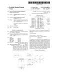
The block diagram of the car hardware is presented in gure 1.
Figure 1: Block diagram of the car hardware
4.1.1 Microcontroller unit
The heart of the car is AVR ATmega32 microcontroller. The AVR microcontroller family is based on 8-bit RISC architecture with 32 general purpose
registers. The ATmega32 can run up to 16 MIPS at 16MHz. It has 32
kB program ash-memory, 2kB RAM memory and 1kB EEPROM memory.
Peripheral features includes 3x Timer/Counter, 8x 10-bit AD-converter, 4x
PWM, USART module (UART, SPI, I2C), and many more. The microcontroller has in-system programming function, the internal program memory
can be programmed via serial programming interface while the microcontroller is mounted in the embedded hardware.
Pin conguration of the AVR ATmega32 is described in table 4.1.1.
7
PIN/BIT(s) Dir
PA 7..0
PB 7..0
PC 7
PC 6
PC 5
PC 4
PC 3
PC 2
PC 1..0
PD 7..6
PD 5
PD 4
PD 3
PD 2
PD 1..0
Description
in
Infra-red sensing bumper
in/out Keybad
out LCD data 3
out LCD data 2
out LCD data 1
out LCD data 0
out LCD enable
out LCD register select
in/out I2C bus (not in use)
Not in use
out Steering servo
out Drive motor control
Not in use
in
Tachometer
in/out Serial port
Table 1: AVR pin assignment
4.1.2 Sensors
The main sensor of the car is the infra-red reection sensing bumper. The
bumper has 8 parallel IR transmitter-receiver pairs, each controlled individually by the peripheral microcontroller of the bumper. The IR-receiver
provides analog voltage proportional to the intensity of received IR-light.
Depending on the value it is possible to determine whether there is reective
tape or plain ooring in beneath of the sensor. The bumper provides 8-bit
parallel signal each bit corresponding to one detector pair. The value of the
bit is high if the reection is above certain threshold value, otherwise low.
The driving motor has feedback tachometer sensor. The sensor provides
6 pulses per full rotation of tire (approx. once every 3 cm). The pulse
frequency from the tachometer is so low that one can not calculate pulses
per time unit, but one must calculate time units between pulses. Use of
the feedback tachometer is important in order to implement ecient and
accurate control algorithm for the car.
4.1.3 Control
The car has driving motor and steering servo. Both devices are controlled
with standard servo control signals (PWM). There is no feedback from the
steering servo, but the steering can be expected being accurate enough. The
control of the driving motor can not be considered proportional. The power
fed to the motor does not correlate well with speed/acceleration. There are
8
factors like charge of batteries, current speed, etc. that aects.
4.1.4 User interface
The user interface of the car consists of 12 button keybad and 16x2 characters
LCD-display. The display is based on standard Hitachi HD44780 driver.
Note that even if the LCD module is standard, it is not connected into the
microcontroller in conventional way; Read/Write signal is not connected.
Thus one may not apply most AVR LCD libraries available in the net.
4.1.5 Computer interface
The computer interface of the car consists of in-system programming interface and serial interface. One may connect personal laptop or other gadget
into the serial port and tune parameters, collect statistics, etc.
4.2
IR-sensor bumper
The IR-sensor bumper is the only sensor of the system that tells about the
external word. The are other sensors like tachometer, but they tell about
the car itself. Thus the IR-sensor is the most important one and the car can
do nothing without it.
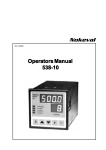
Figure 2: IR-sensor system
The bumper as number of infrared transmitter-receiver pairs parallel in
front of the car, as shown in gure 2. If there is reective tape below the
receiver, the reection of the IR light is higher and the receiver gets stronger
signal compared to plain ooring.
9
4.2.1 Requirements
The IR bumper has following special requirements:
• mechanically robust structure
• electrically reliable (single PCB, high quality manufacturing)
• bumper width conforming with the width of the car body
• many enough IR transmitter-receiver pairs
• active electronics with on board microcontroller
• analog sensor measurement
• parallel-I/O output signal ON/OFF
• serial bi-directional communication
• visible light indicator LEDs for IR transmitters and receivers
• software adjustable parameters (threshold etc.)
• in-circuit programmable
4.2.2 Design rationale
Microcontroller Atmel 8-bit AVR microcontroller family is the controller
of choice. The controller must have three full 8bit I/O ports for sensor
operation; one port for IR-led control output, one port with AD-conversion
for IR-sensor and one port for parallel-I/O with main system. In addition
some extra pins are required for serial communication and other purposes.
Thus the controller must have four ports.
ATmega16 and ATmega32 controllers oer required I/O capacity. One
port is equipped with multiplexed 10bit AD-converter. These two chips
have identical pin congurations, only the amount of memory diers (16kB
of ash program memory in the ATmega16 and 32kB in the Mega32). Thus
the choice is just a matter of taste. In order to make it possible to run more
complicated software in the future, it is vice to choose the bigger one.
There are other versions, like ATmega48, that oer enough I/O pins
just for the main operation: 8-bit transmit led output, 8-pin receiver analog
input, and 8-bit external IO. However, there are no extra pins available for
any additional functionality, like simultaneous serial communication or extra
indicator LEDs. Thus favoured choice is a bigger controller like the Mega16.
ATmega -series of microcontrollers have internal calibrated RC-oscillator
to provide clock source for the controller. The frequency of the oscillator is
10
not exact, there is a variance of few percent depending on operation temperature and voltage. Maximum clock frequency with the internal oscillator
is 8 Mhz. The application is not timing critical. The limiting factor is the
speed of the AD-conversion, and that's well below the speed of the controller
computational core. Thus the code will spend greater deal of the time just
waiting for nalisation of the AD-conversion. Internal oscillator can be considered good enough for the application in question.
Analog measurement In the old bumper there was only available a digital ON/OFF signal per detector indicating wether a reection strong enough
was detected or not. For just the car application only, that is sucient to do
the job. However, it is reasonable to make it possible to use more complicated
sensing algorithms later on. By providing analog reection illumination measurement value per each detector, and propably cross detector, it is possible
to implement much more accurate positioning of the reective tape track.
In addition, such an analog measurement allows calibration of sensor
threshold and other parameters on-y. In beginning of each race the team
can calibrate the bumper to the current ambient illumination conditions in
order to decrease false detections. In a broader sense, it is wise to make the
bumper as modular as possible, to make it possible to use the bumper in other
appliances as the RC car. Or use it with dierent kind of track. With analog
measurements the bumper can detect dierences in surface reection related
to colour or material of the surface (tiled ooring) in order to navigate. Thus
the bumper can easily be adopted in other robotic solutions as well.
Surface mount components In order to improve the endurance of the
device, it is better to have no components sticking out of the board. Most
of the components required for the device are available in SMD versions, including microcontroller, IR emitters and receivers, and passive components
(resistor, capacitor). In fact, IR receivers are already purchased in SMD
components: TAOS TSL261RD 'Monolithic Silicon IC Containing Photodiode, Operational Amplier, and Feedback Components'. The component
is equipped with Visible Light-Cuto Filter Plastic to improve tolerance
against ambient light sources. The center frequency of the receiver is 940
nm (infra-red).
Serial communication Bi-directional serial communication path does not
only allow reading of analog measurement values, but makes it possible to
set parameters of the bumper sensing on-y by the main controller board.
The ATmega-series of microcontrollers has built-in hardware support for
traditional serial port (RS-232/IEA-232), I2C bus and SPI bus. Serial port
is the most traditional one. However, lack of natural framing support makes
it hard to design robust communication protocol. The SPI is very has and
11
reliable, but it has other limitations. I2C is considered as the best choice for
the serial communication.
I2C is a synchronous multi-node multi-master bus with addressing and
frame support. There is a clear start and stop condition for each data frame
and designer does not need to develop an upper-layer protocol to implement a
robust communication protocol. The bus is synchronous and always clocked
by the current master. There is also a arbitration mechanism for multimaster collision prevention.
The bus is originally designed for inter-ic within a single system or circuit
board. With short cables a it i possible to use the bus without any additional
arrangements. With longer cables (several meters) a special impedance converter and/or reduced clock speed is required. The specied standard maximum speed for the bus is 400 kHz, which is well enough to deliver bumper
data frequently enough.
4.2.3 Mechanics
It is reasonable to keep the mechanical design of the bumper as simple as
possible (KISS-theorem). The simplest way, yet robust enough, is to stack
a sandwich by placing the circuit board in between two transparent plastic
Plexiglas plates and bolting them together, as shown in upper picture of
gure 3. As all the components are surface mounted, the whole circuit board
remains thin and the thickness of the bumper remains in less than 15 mm.
In the way the circuit board and components are well protected, yet allowing
the infra-red sensor system working and keeping debugging indicator LEDs
well visible.
Figure 3: Mechanical structure, side view
The problem of the design are direct IR-beams from a transmitter to a
receiver. In the lower picture of gure 3 the problem is solved by placing a
12
drilled non-transparent plastic plate in the bottom-side of the PCB. There
are holes drilled in the place of transmitter and receiver components. No
other components are placed in bottom-side. The non-transparent plexi
acts as a IR-radiation shield preventing direct beams from transmitter to
receiver. At the same time it narrows the angle of transmitter and receiver,
subsequently decreasing interference between transmitter-receiver pairs.
4.2.4 Schematics
Schematic diagram of the IR bumper is presented in appendix A. In the left
side of the diagram is the ATmega16 microcontroller chip with it's supply
voltage circuits. The zero-ohm resistor R0 provides single point of connection
in between digital and analog ground.
Inductor L1 and capacitor C13 provides high-frequency interference protection by low-pass ltering for analog supply voltage Vdd. A/D converter of
the ATmega16 is fed by that voltage. In addition analog supply is delivered
for infrared receiver circuits.
Connectors are located in the bottom of the diagram. There are 2x8 pin
data connector, 2x5 pin in-system programming connector (ISP), and 2x5
pin JTAG connector. Connector pinouts are detailed in section 4.2.6.
In the middle of the diagram are indicator LEDs and their driver circuits
(ULN2803A octal darlington-transistor array) located. A single I/O pin of
the AVR microcontroller can source or sink up to 40mA current, but several
such currents at the same time exceeds the total current specications of
the controller. Thus all indicator LEDs and infrared LEDs are driven by
darlington transistor buers.
In the right side of the schematic diagram are located infrared transmitter
LEDs and receiver circuits (TSL261RD Light-to-voltage optical sensor) with
their analog supply voltage lters. Each receiver circuit has a low-pass RClter to prevent any interference from other parts of the system. Analog
output signals are delivered to A/D converter of the AVR.
4.2.5 Circuit board
The printed circuit board of the bumper has total dimensions of 205 x 65
mm. The board is double-sided with through-hole copper. The board is
covered with protective green epoxy solder mask. Images of board copper
layers and component layouts are presented in appendix A.
Most of the components are located in the top side of the board, only IR
transmitters and receivers are located in the bottoms side, and two resistors
which didn't had convenient place in the top side.
Circuit boards are manufactured by Futurlec Inc. in Thailand:
http://www.futurlec.com/
13
4.2.6 Connectors
Data The bumper data connector includes 8-bit parallel bus and serial I2C
bus. In addition there are two extra bits for interrupt and other purposes.
The pinout of the connecter is presented in table 4.2.6.
1 GND
2 D0 (PD0)
3 GND
4 D1 (PD1)
5 GND
6 D2 (PD2)
7 SCL (PC0) 8 D3 (PD3)
9 SDA (PC1) 10 D4 (PD4)
11 (PC6)
12 D5 (PD5)
13 PC(7)
14 D6 (PD6)
15 Vcc
16 D7 (PD7)
Table 2: bumper data connector
The in-system programming connector (ISP)
conforms with Atmel's STK200 development board. The connector pinout
is presented in table 4.2.6.
1 MOSI (PB5) 2 Vcc
3 4 GND
5 RST
6 GND
7 SCK (PB7) 8 GND
9 MISO (PB6) 10 GND
Table 3: bumper ISP connector
In-system programmin
The JTAG programming and in-system debugging interface connector conforms with Atmel's AVR-JTAG connector. The connector pinout
is presented in table 4.2.6.
1 TCK (PC2) 2 GND
3 TMS (PC4) 4 Vcc
5 TDO (PC3) 6 RST
7 Vcc
8 9 TDI (PC5) 10 Table 4: bumper JTAG connector
JTAG
14
4.2.7 Design aws
The rst version of the bumper electronics has a few design aws:
• Analog reference voltage of the AD-converter of the AVR is connected
to analog ground. Should be left open or have a capacitor inbetween.
At board assembly the wire must be cut o.
• Data and JTAG connectors are missing protective series connector. In
the car assembly these are mounted in the cable connecting the bumper
to the MCU board.
• Data connector pins are swapped compared to pin order of the MCU
board connector (1 and 2 are swapped and so on). The cable must x
the problem by swapping corresponding signals.
• Transmit indicator LEDs LED-T0..LED-T7 are in wrong order. Actual
IR transmitter LEDs are correct but visible light indicator LEDs are
swapped.
4.3
MCU board
The main MCU board of the car is a ready made industrial controller unit
Embmega32 from Ere Co. Ltd, Thailand.
http://www.ere.co.th/
Manufacturer describes the board as follows:
EMBMEGA32 is an embedded microcontroller board based
on ATMEGA32 AVR microcontroller family.It is low cost and
exible,making it ideal as an embedded controller.Normal speed
of board is 16MHz and 14.7456 MHz.The board has 4 ports (32
I/O lines),a mini buzzer,reset switch and one RS232 port.Also it
has two options, one is serial eeprom 24XX family and one is real
time clock DS1307 with 3-volt lithium battery.The board has lcd
connector for common character lcd module,with contrast pot,
power supply and current limit resister for backlight.All ports
on the board are connected to IDC connectors but ADC connections are available using terminals.PCB is a two-layer with design
GGGP intended for demanding industrial applications.The board
provides 10 pins serial ISP header for hooking up to ISPAVRP2
which download a code to the board without a ash programmer.
4.3.1 Schematics
Schematic diagram is presented in the Embmega32 schematics data sheet
and user manual.
15
4.3.2 Connectors
Connector placement is presented in appendix D.
IO Port All the four I/O ports of the AVR are available via 2x8 pin
connectors. All the connectors have the following pin order:
1 D0 2 GND
3 D1 4 GND
5 D2 6 GND
7 D3 8 GND
9 D4 10 GND
11 D5 12 GND
13 D6 14 GND
15 D7 16 Vcc
Table 5: MCU board IO port connectors
LCD-display The LCD display connector interfaces an industry standard
Hitachi HD44780 character dot matrix LCD display driver in 4-bit mode.
However, the R/W bit of the interface is not connected, thus one can not
poll the status of the busy ag of the display. Instead, a delay interval long
enough must be implemented in the software.
1 +5V 2 GND
3 RS 4 VO
5 E 6 GND
7 GND 8 GND
9 GND 10 GND
11 D5 12 D4
13 D7 14 D6
15 BL- 16 BL+
Table 6: MCU board IO port connectors
Pin 15 and 16 provides voltage for LCD display back light. There is
no series resistor in this power supply, thus there must be a resistor with
suitable value in the display component, if back light is used.
ISP The in-system programming connector of the Embmega32 has a pin
order which is totally incompatible with any de-facto standard pinout. An
16
adapter cable or custom made programming cable is required to program
this device.
The pin order of the connector is presented in the table 4.3.2.
1 - 2 MOSI
3 - 4 MISO
5 - 6 SCK
7 - 8 RST
9 Vcc 10 GND
Table 7: MCU board ISP connector
Wirings for very simple custom made parallel port connected ISP cable
for the Embmega32 is presented in table 4.3.2. The cable has four series resistors 100..1k ohm.It is compatible with UISP and AvrDUDE programming
softwares in DAPA (direct access) mode.
D25
ISP
1. Strobe -[ 470 ohm ]- 6. SCK
2. Data 0 -[ 470 ohm ]- 2. MOSI
11. Busy -[ 470 ohm ]- 4. MISO
16. Init -[ 470 ohm ]- 8. RST
19. Ground - 10. GND
Table 8: MCU board ISP programming cable
4.4
Tachometer
Tachometer provides rotation feedback for motor control.
4.4.1 Requirements
The same basic requirements apply to the tachometer: robust mechanics,
reliable electronics and inexpensive components. High accuracy is not a
critical issue. It is enough to get more than one pulse per rotation. It is
not necessary to determine the direction of rotation. One should know the
direction anyway.
4.4.2 Mechanics
Due to the mechanical structure of the car, it is not feasible to attach the
tachometer directly to the motor. Instead it is much easier to mount it to the
wheel axle. Due to the planetary gear of the transmission, the tachometer
17
does not indicate exact rotation speed of the motor. There may occur minor
error when the car is turning or tires are slipper.
The sensor of the tachometer consist of infra-red optical sensor and perforated disk. The disk has six holes, thus six pulses are available per full
rotation of the tire. Interval between pulses represent distance of apx. 3.1
mm. Due to the nature of the tachometer, the application software can not
count pulses per time unit but it must count time unit between pulses.
4.4.3 Schematics and circuit board
Schematic diagram and circuit board layout of the tachometer are presented
in appendix B. The circuit consists of infrared sensor, connectors and servo
signal indicators. There are three dummy connector pads for signals which
are currently not in use.
4.4.4 Connectors
1
3
5
7
9
11
13
15
GND 2 GND 4 GND 6 Tachometer (PD2/ExtInt0)
GND 8 Spare (PD3)
GND 10 Servo 1 (PD4/OC1A)
GND 12 Servo 2 (PD5/OC1B)
GND 14 Spare (PD6)
Vcc 16 Spare (PD7)
Table 9: Tachometer connector
Tachometer connector
1 Signal
2 Vcc
3 GND
Table 10: Servo connector
Servo and spare signal connectors
4.4.5 Design aws
The rst version of the tachometer circuit has a few design aws:
18
Tachometer connector has pins in wrong order. Pins 1 and 2 are
swapped and so on. This must be xed by a cable that swaps the
pins correspondingly.
• Tachometer signal is missing protective series resistor.
•
19
5
5.1
Software
bumper code
Simple, yet functional, bumper code is presented in appendix C. The code
switches one IR LED on at a time and measures corresponding analog signal
level to determine wether predened threshold value is exceeded.
The code has some improvements, as dened in le header:
Theory of operation:
- Ambient interference compensation:
Each sensor is measured twice. Once with IR-illumination led on
and once without IR-light. Values are subtracted to remove the
affection of ambient light
- Low-pass filtering
Minor errors are filtered by averaging. For each bit last
FILTER_COUNT (10) measurements are summed together. The must be
at least FILTER_THRESHOLD (3) values exceeding THRESHOLD value for
the bit to be interpreted as one.
- Extended validity
The is a black-out gap in between sensors. In order not to loose
signal immediately, the last non-zero value is considered good
for VALID_COUNT (10) rounds until the value is cleared.
5.2
Main control code
No ready-made code is provided for the MCU of the car, as it is students'
task to implement a control code.
20
6
Conclusions
At the moment of writing this document, the hardware is in use by students
executing the course project work. Consequently no nal conclusions of the
success of the project can by drawn yet.
First versions of schematics and PCB of bumper and tachometer contains some errors. None of these errors are fatal or show-stopper, thus the
hardware can be used with minor work-around.
All subsystems of the car are tested and functioning properly. A simple
test code using all the functions is implemented to demonstrate usability of
the system. There is no reason to believe that the project will fail in a sense
of students not learning programming embedded systems. In any case the
hardware is far more better and suitable for the course than the old one.
6.1
Future improvements
If new releases are introduced, design aws in bumper and tachometer circuit
board should be xed. Primarily this includes xing pin order of connectors
and adding protective series resistors in signal lines.
Possible future enhancement would be telemetry application; transmitting real-time data from the car to a PC over wireless RF-link. Additional
sensors for safety and status information would be nice. Ultrasonic or infrared proximity detectors would help prevent accidents with solid objects
(wall, human leg, etc).
Reliable odometer would improve capability of learning the track. It rst
round the car records track features and then it can drive faster as it can preempt coming cources. It is possible to do that with the current tachometer,
but reading are not very accurate; tires may slip. With acceleration sensors
it would be possible to determine wether the car is moving as indicated by
tachometer.
21
A
IR Bumper
Figure 4: Bumper schematics
22
Figure 5: Bumper PCB: Top copper layer
Figure 6: Bumper PCB: Bottom copper layer
Figure 7: Bumper PCB: Component top layout
23
Figure 8: Bumper PCB: Component bottom layout
24
B
Tachometer
Figure 9: Tachometer schematics
25
Figure 10: Tachometer PCB: Copper top layer
Figure 11: Tachometer PCB: Copper bottom layer
26
Figure 12: Tachometer PCB: Component top layout
Figure 13: Tachometer PCB: Component bottom layout
27
C
Bumper software
puskuri.c
/* Improved IR-sensor bumper implementation
* for Project Work Car.
*
* Helsinki University of Technology
* Department of Computer Science
* Laboratory of Software Technology
* Course of Embedded Systems
*
* Version 0.2
*
* Jaakko Ala-Paavola
* 2006/02/05
*
* Notice:
* There is a bug in the bumper PCB layout.
* Infrared LED and corresponding indicator LED
* are swapped in position.
*
* Theory of operation:
* - Ambient interference compensation:
*
Each sensor is measured twice. Once with IR-illumination led on
*
and once without IR-light. Values are subtracted to remove the
*
affection of ambient light
* - Low-pass filtering
*
Minor errors are filtered by averaging. For each bit last
*
FILTER_COUNT (10) measurements are summed together. The must be
*
at least FILTER_THRESHOLD (3) values exceeding THRESHOLD value for
*
the bit to be interpreted as one.
* - Extended validity
*
The is a black-out gap in between sensors. In order not to loose
*
signal immediately, the last non-zero value is considered good
*
for VALID_COUNT (10) rounds until the value is cleared.
*
*/
#include <avr/io.h>
#include <avr/signal.h>
#include <avr/interrupt.h>
#include "puskuri2.h"
28
//#define TEST_MODE
#ifdef TEST_MODE
#define MUX_BASE (_BV(REFS1) | _BV(REFS0) | _BV(ADLAR)) + 2
#else
#define MUX_BASE (_BV(REFS1) | _BV(REFS0) | _BV(ADLAR))
#endif
unsigned
unsigned
unsigned
unsigned
unsigned
unsigned
unsigned
unsigned
char
char
char
char
char
char
char
char
bitno = 0;
pulsecount = 0;
state = 0;
diff = 0;
value = 0;
filter[FILTER_COUNT];
filter_pos = 0;
valid_count = 0;
int main (void) {
// Initialize I/O
LED_DIR = 0xff;
LED_PORT = 0x80;
// All output
// First LED on
LINE_DIR = 0xff;
LINE_PORT = 0x00;
// All output
// All signals low
// Initialize ADC
ADMUX = MUX_BASE;
// Internal 2.56V reference, right adjusted
ADCSRA = _BV(ADEN) | // ADC Enabled
_BV(ADSC) | // Start conversion
_BV(ADIE) | // ADC interrupt enabled
_BV(ADPS2); // Prescaler /16
// Global interrupt enable
sei();
}
return 0;
SIGNAL (SIG_ADC) {
unsigned char average, pos;
29
// Read the sensor value and set line signal
if (state) {
diff -= ADCH;
#ifdef TEST_MODE
if (bitno == 3) {
LINE_PORT = diff;
}
#else
// Set value into filter bit matrix
if (diff > THRESHOLD)
//
LINE_PORT |= line_bit;
filter[filter_pos] |= 0x01<<bitno;
else
//
LINE_PORT &= ~line_bit;
filter[filter_pos] &= ~(0x01<<bitno);
// Compute filter averages
if (++bitno >= BIT_COUNT) {
if (++filter_pos > FILTER_COUNT)
filter_pos = 0;
for (bitno=0; bitno < BIT_COUNT; bitno++) {
average = 0;
}
for (pos = 0; pos < FILTER_COUNT; pos++) {
if (filter[pos] & (1<<bitno))
average++;
}
if (average > FILTER_THRESHOLD)
value |= (1<<bitno);
else
value &= ~(1<<bitno);
// If null value from sensors, maintain
// old value for VALID_COUNT times.
if (value) {
30
LINE_PORT = value;
valid_count = 0;
} else {
if (++valid_count > VALID_COUNT)
LINE_PORT = 0;
}
//
LINE_PORT = value;
bitno = 0;
}
//
//
if (bitno == 7 && value != 0)
LINE_PORT = value;
#endif
// Prepare new concersion
// Turn on next led
LED_PORT = (0x80>>bitno);
// Set MUX
ADMUX = (MUX_BASE) | bitno;
state = 0;
} else { // state == 0
}
}
diff = ADCH;
LED_PORT = 0; // turn led off for reference measurement
state = 1;
// Trigger new conversion
ADCSRA |= _BV(ADIF) | _BV(ADSC);
puskuri.h
/* Improved IR-sensor pumber implementation
* for Project Work Car.
*
31
* Helsinki University of Technology
* Department of Computer Science
* Laboratory of Software Technology
* Course of Embedded Systems
*
* Version 0.2
*
* Jaakko Ala-Paavola
* 2006/02/05
*
* Notice:
* There is a bug in the pumber PCB layout.
* Infrared LED and corresponding indicator LED
* are swapped in position.
*
* Theory of operation:
* - Ambient interference compensation:
*
Each sensor is measured twice. Once with IR-illumination led on
*
and once without IR-light. Values are substracted to remove the
*
affection of ambient light
* - Low-pass filtering
*
Minor errors are filtered by averaging. For each bit last
*
FILTER_COUNT (10) measurements are summed together. The must be
*
at least FILTER_THRESHOLD (3) values exceeding THRESHOLD value for
*
the bit to be interpreted as one.
* - Extended validity
*
The is a black-out gap in between sensors. In order not to loose
*
signal immediately, the last non-zero value is considered good
*
for VALID_COUNT (10) rounds untill the value is cleared.
*
*/
#ifndef __PUSKURI_H
#define __PUSKURI_H
#define
#define
#define
#define
#define
THRESHOLD 0x30
FILTER_COUNT 10
FILTER_THRESHOLD 3
BIT_COUNT 8
VALID_COUNT 10
/* --- Hardware definitions --- */
#define LED_PORT
PORTB
32
#define LED_DIR
DDRB
#define LINE_PORT
#define LINE_DIR
PORTD
DDRD
#define
#define
#define
#define
PULSE_PORT PORTC
PULSE_DIR
DDRC
PULSE_IN
PINC
PULSE_PIN
PC7
#endif
Makele
# Helsinki University of Technology
# T-106.530 Embedded systems
#
# AVR-GCC Makefile
#**************************************************************
.SUFFIXES:
.SUFFIXES:
.S .c .o .cof .elf .eep .rom
#--- define some variables based on the AVR base path in $(AVR)
CC
= avr-gcc
AS
= avr-gcc
RM
= rm -f
RN
= mv
CP
= cp
BIN
= avr-objcopy
ELFCOF = avr-objdump
#ELFCOF = objtool
INCDIR = .
#If all other steps compile ok then echo "Errors: none".
#Necessary for AVR Studio to understand that everything went ok.
DONE
= @echo Errors: none
#--- default mcu type
MCU = atmega16
#--- default compiler flags -ahlmsn
CPFLAGS = -g -Os -funsigned-char -funsigned-bitfields -fpack-struct -fshort-enum
s -Wall -Wstrict-prototypes -mmcu=$(MCU) -Wa,-ahlmsnd=$(<:.c=.lst)
33
#--- default assembler flags
ASFLAGS = -mmcu=$(MCU) -Wa,-mmcu=$(MCU),-gstabs
#--- default linker flags
LDFLAGS = -Wl,-Map=$(<:.o=.map),--cref -mmcu=$(MCU)
#--- output format can be srec (Motorola), ihex (Intel HEX)
ROMFORMAT
= srec
EEPROMFORMAT
= ihex
# AVR Studio needs Intel HEX format
#--- compile: instructions to create assembler and/or object files from C source
#.c.o:
%o : %c
$(CC) -c $(CPFLAGS) -I$(INCDIR) $< -o $@
%s : %c
$(CC) -s $(CPFLAGS) -I$(INCDIR) $< -o $@
#--- assemble: instructions to create object file from assembler source
%o : %S
$(AS) -x assembler-with-cpp $(ASFLAGS) -I$(INCDIR) -c $< -o $@
%: %.c
@echo "Error: target $@ not defined in Makefile"
@exit 1
#--- link: instructions to create elf output file from object files
%elf: %o
$(CC) $^ $(LIB) $(LDFLAGS) -o $@
#--- create AVR Studio cof file from elf output file and map file
%cof: %elf
$(ELFCOF) loadelf $^ mapfile $(<:.elf=.map) writecof $@
#--- create flash and eeprom bin file (ihex, srec) from elf output file
%rom: %elf
$(BIN) -O $(ROMFORMAT) -R .eeprom $< $@
%eep: %elf
$(BIN) -j .eeprom --set-section-flags=.eeprom="alloc,load" --change-sect
34
ion-lma .eeprom=0 -O $(EEPROMFORMAT) $< $(@:.elf=.eep)
#*************************** add your projects below **************************
#--- this defines the aims of the make process
all:
puskuri
clean:
$(RM)
$(RM)
$(RM)
$(RM)
$(RM)
*.rom *.eep *.cof
*.o
*.elf
*.lst
*.map
#-------- test
puskuri:
puskuri.rom #puskuri.cof
$(DONE)
puskuri.elf:
puskuri.o
puskuri.o:
puskuri.c puskuri.h
35
D
MCU board
Figure 14: Embmega32 board layout
36