1
SAFETY PRECAUTIONS
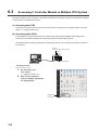
(Read these precautions before using this product.)
Before using this product, please read this manual and the relevant manuals carefully and pay full attention
to safety to handle the product correctly.
The instructions given in this manual are concerned with this product only. For the safety instructions of the
programmable controller system, please read the CPU module user's manual.
In this manual, the safety precautions are classified into two levels: "
WARNING" and "
CAUTION".
WARNING
Indicates that incorrect handling may cause hazardous conditions,
resulting in death or severe injury.
CAUTION
Indicates that incorrect handling may cause hazardous conditions,
resulting in minor or moderate injury or property damage.
Under some circumstances, failure to observe the precautions given under "
CAUTION" may lead to
serious consequences.
Observe the precautions of both levels because they are important for personal and system safety.
Make sure that the end users read this manual and then keep the manual in a safe place for future
reference.
1
[Design Precautions]
WARNING
● Configure safety circuits external to the C Controller module to ensure that the entire system
operates safely even when a fault occurs in the external power supply or the C Controller module.
For the following controls, configure an interlock circuit in the user program to ensure that the entire
system will always operate safely.
(1) Changing data of the running C Controller module from the development environment (personal
computer) connected
(2) Changing the operating status
(3) Operating from the development environment (personal computer)
Especially, in the case of control from an external device to a remote C Controller module, immediate
action cannot be taken for a problem on the C Controller module due to a communication failure.
To prevent this, configure an interlock circuit in the user program, and determine corrective actions to
be taken between the external device and C Controller module in case of a communication failure.
[Setup and Maintenance Precautions]
WARNING
● Configure safety circuits external to the C Controller module to ensure that the entire system
operates safely even when a fault occurs in the external power supply or the C Controller module.
For the following controls, configure an interlock circuit in the user program to ensure that the entire
system will always operate safely.
(1) Changing data of the running C Controller module from the development environment (personal
computer) connected
(2) Changing the operating status
(3) Operating from the development environment (personal computer)
Especially, in the case of control from an external device to a remote C Controller module, immediate
action cannot be taken for a problem on the C Controller module due to a communication failure.
To prevent this, configure an interlock circuit in the user program, and determine corrective actions to
be taken between the external device and C Controller module in case of a communication failure.
CAUTION
● Before performing online operations (especially, program modification, forced output, and operation
status change) for the running C Controller module from the peripheral connected, read relevant
manuals carefully and ensure the safety.
Improper operation may damage machines or cause accidents.
2
CONDITIONS OF USE FOR THE PRODUCT
(1) Mitsubishi C Controller system ("the PRODUCT") shall be used in conditions;
i) where any problem, fault or failure occurring in the PRODUCT, if any, shall not lead to any major
or serious accident; and
ii) where the backup and fail-safe function are systematically or automatically provided outside of
the PRODUCT for the case of any problem, fault or failure occurring in the PRODUCT.
(2) The PRODUCT has been designed and manufactured for the purpose of being used in general
industries.
MITSUBISHI SHALL HAVE NO RESPONSIBILITY OR LIABILITY (INCLUDING, BUT NOT
LIMITED TO ANY AND ALL RESPONSIBILITY OR LIABILITY BASED ON CONTRACT,
WARRANTY, TORT, PRODUCT LIABILITY) FOR ANY INJURY OR DEATH TO PERSONS OR
LOSS OR DAMAGE TO PROPERTY CAUSED BY the PRODUCT THAT ARE OPERATED OR
USED IN APPLICATION NOT INTENDED OR EXCLUDED BY INSTRUCTIONS, PRECAUTIONS,
OR WARNING CONTAINED IN MITSUBISHI'S USER, INSTRUCTION AND/OR SAFETY
MANUALS, TECHNICAL BULLETINS AND GUIDELINES FOR the PRODUCT.
("Prohibited Application")
Prohibited Applications include, but not limited to, the use of the PRODUCT in;
• Nuclear Power Plants and any other power plants operated by Power companies, and/or any
other cases in which the public could be affected if any problem or fault occurs in the PRODUCT.
• Railway companies or Public service purposes, and/or any other cases in which establishment of
a special quality assurance system is required by the Purchaser or End User.
• Aircraft or Aerospace, Medical applications, Train equipment, transport equipment such as
Elevator and Escalator, Incineration and Fuel devices, Vehicles, Manned transportation,
Equipment for Recreation and Amusement, and Safety devices, handling of Nuclear or
Hazardous Materials or Chemicals, Mining and Drilling, and/or other applications where there is a
significant risk of injury to the public or property.
Notwithstanding the above, restrictions Mitsubishi may in its sole discretion, authorize use of the
PRODUCT in one or more of the Prohibited Applications, provided that the usage of the PRODUCT
is limited only for the specific applications agreed to by Mitsubishi and provided further that no
special quality assurance or fail-safe, redundant or other safety features which exceed the general
specifications of the PRODUCTs are required. For details, please contact the Mitsubishi
representative in your region.
3
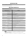
INTRODUCTION
Thank you for purchasing the C Controller module.
Before using this product, please read this manual carefully and develop familiarity with the functions and performance of the
C Controller module to handle the product correctly.
RELEVANT MANUALS
The following manuals are relevant to this product.
Order each manual as needed, referring to the table below.
Manual name
Description
<Manual number, code>
MELSEC-Q C Controller Module User's Manual
<SH-081130ENG, 13JZ75>
CW Workbench Operating Manual
<SH-080982ENG, 13JU71>
CW-Sim Operating Manual
The manual describes system configuration, specifications, functions, handling
methods, wiring, troubleshooting, and programming and function of the C
Controller module.
The manual describes system configuration, specifications, functions, and
troubleshooting of CW Workbench.
The manual describes system configuration, specifications, functions, and
<SH-081159ENG, 13JU77>
troubleshooting of CW-Sim.
GX Works2 Version 1 Operating Manual
The manual describes the system configuration of GX Works2 and the functions
(Common)
common to Simple project and Structured project such as parameter setting,
<SH-080779ENG, 13JU63>
operation method for the online function.
GX Works2 Version 1 Operating Manual
The manual describes the methods of intelligent function module for such as
(Intelligent Function Module)
parameter setting, monitoring programs, and predefined protocol support
<SH-080921ENG, 13JU69>
QCPU User's Manual
(Hardware Design, Maintenance and Inspection)
<SH-080483ENG, 13JR73>
QCPU User's Manual
function in GX Works2.
The manual describes specifications of the CPU module, the power supply
module, the base unit, the extension cable, the memory card, etc.
The manual describes overview, system configuration, I/O number,
(Multiple CPU System)
communication between CPU modules, and communication with I/O module/
<SH-080485ENG, 13JR75>
intelligent function module of multiple CPU system.
Q Corresponding MELSECNET/H Network System
The manual describes the PLC-to-PLC network specifications, preparatory
Reference Manual (PLC to PLC network)
procedures and settings, parameter setting, programming, and troubleshooting
<SH-080049, 13JF92>
for the MELSECNET/H network system.
CC-Link IE Controller Network
The manual describes system configurations, performance specifications,
Reference Manual
functions, handling instructions, wiring, and troubleshooting for the CC-Link IE
<SH-080668ENG, 13JV16>
Controller Network system.
MELSEC-Q CC-Link IE Field Network
The manual describes system configurations, performance specifications,
Master/Local Module User's Manual
functions, handling instructions, wiring, and troubleshooting for the CC-Link IE
<SH-080917ENG, 13JZ47>
Field Network system.
MELSEC-Q CC-Link System Master/Local Module
The manual describes system configurations, performance specifications,
User's Manual
functions, handling instructions, wiring, and troubleshooting for the CC-Link
<SH-080394E, 13JR64>
modules.
CC-Link/LT Master Module
The manual describes system configurations, performance specifications,
User's Manual
functions, handling instructions, wiring, and troubleshooting for the CC-Link/LT
<SH-080351E, 13JR62>
modules.
Remark
Manuals in printed form are sold separately for single purchase. Order a manual by quoting the manual number
(model code) listed in the table above.
4
Memo
5
CONTENTS
CONTENTS
SAFETY PRECAUTIONS . . . . . . . . . . . . . . . . . . . . . . . . . . . . . . . . . . . . . . . . . . . . . . . . . . . . . . . . . . . . . 1
CONDITIONS OF USE FOR THE PRODUCT . . . . . . . . . . . . . . . . . . . . . . . . . . . . . . . . . . . . . . . . . . . . . 3
INTRODUCTION . . . . . . . . . . . . . . . . . . . . . . . . . . . . . . . . . . . . . . . . . . . . . . . . . . . . . . . . . . . . . . . . . . . . 4
RELEVANT MANUALS . . . . . . . . . . . . . . . . . . . . . . . . . . . . . . . . . . . . . . . . . . . . . . . . . . . . . . . . . . . . . . . 4
HOW TO READ THIS MANUAL . . . . . . . . . . . . . . . . . . . . . . . . . . . . . . . . . . . . . . . . . . . . . . . . . . . . . . . 10
GENERIC TERMS AND ABBREVIATIONS . . . . . . . . . . . . . . . . . . . . . . . . . . . . . . . . . . . . . . . . . . . . . . 12
MEANINGS AND DEFINITIONS OF TERMS . . . . . . . . . . . . . . . . . . . . . . . . . . . . . . . . . . . . . . . . . . . . . 13
CHAPTER 1 OVERVIEW
14
1.1
Product Overview . . . . . . . . . . . . . . . . . . . . . . . . . . . . . . . . . . . . . . . . . . . . . . . . . . . . . . . . . . . 14
1.2
Features . . . . . . . . . . . . . . . . . . . . . . . . . . . . . . . . . . . . . . . . . . . . . . . . . . . . . . . . . . . . . . . . . . 14
1.3
List of Functions . . . . . . . . . . . . . . . . . . . . . . . . . . . . . . . . . . . . . . . . . . . . . . . . . . . . . . . . . . . . 16
CHAPTER 2 SYSTEM CONFIGURATION
21
2.1
Connection from USB Port . . . . . . . . . . . . . . . . . . . . . . . . . . . . . . . . . . . . . . . . . . . . . . . . . . . . 21
2.2
Connection from Ethernet Port . . . . . . . . . . . . . . . . . . . . . . . . . . . . . . . . . . . . . . . . . . . . . . . . . 21
2.3
Modules connectable from USB port, Ethernet board . . . . . . . . . . . . . . . . . . . . . . . . . . . . . . . 22
CHAPTER 3 SCREEN CONFIGURATION AND BASIC OPERATIONS
23
3.1
Starting and Exiting. . . . . . . . . . . . . . . . . . . . . . . . . . . . . . . . . . . . . . . . . . . . . . . . . . . . . . . . . . 23
3.2
Screen Configuration and Basic Operations. . . . . . . . . . . . . . . . . . . . . . . . . . . . . . . . . . . . . . . 24
3.3
3.2.1
Main frame configuration . . . . . . . . . . . . . . . . . . . . . . . . . . . . . . . . . . . . . . . . . . . . . . . . . . . . 24
3.2.2
Toolbars . . . . . . . . . . . . . . . . . . . . . . . . . . . . . . . . . . . . . . . . . . . . . . . . . . . . . . . . . . . . . . . . . 25
3.2.3
Work windows . . . . . . . . . . . . . . . . . . . . . . . . . . . . . . . . . . . . . . . . . . . . . . . . . . . . . . . . . . . . 27
3.2.4
Docking windows . . . . . . . . . . . . . . . . . . . . . . . . . . . . . . . . . . . . . . . . . . . . . . . . . . . . . . . . . . 32
3.2.5
Navigation window . . . . . . . . . . . . . . . . . . . . . . . . . . . . . . . . . . . . . . . . . . . . . . . . . . . . . . . . . 34
3.2.6
Status bar . . . . . . . . . . . . . . . . . . . . . . . . . . . . . . . . . . . . . . . . . . . . . . . . . . . . . . . . . . . . . . . . 35
Help Function . . . . . . . . . . . . . . . . . . . . . . . . . . . . . . . . . . . . . . . . . . . . . . . . . . . . . . . . . . . . . . 36
3.3.1
Displaying manuals . . . . . . . . . . . . . . . . . . . . . . . . . . . . . . . . . . . . . . . . . . . . . . . . . . . . . . . . 36
3.3.2
Displaying function help . . . . . . . . . . . . . . . . . . . . . . . . . . . . . . . . . . . . . . . . . . . . . . . . . . . . . 36
3.3.3
Checking version of Setting/monitoring tools for the C Controller module. . . . . . . . . . . . . . . 36
CHAPTER 4 PROJECT MANAGEMENT
4.1
37
Configuration of Workspace/Project of Setting/Monitoring Tools for the C Controller
Module . . . . . . . . . . . . . . . . . . . . . . . . . . . . . . . . . . . . . . . . . . . . . . . . . . . . . . . . . . . . 37
4.2
4.3
6
Basic Operations of Project . . . . . . . . . . . . . . . . . . . . . . . . . . . . . . . . . . . . . . . . . . . . . . . . . . . 38
4.2.1
Creating projects . . . . . . . . . . . . . . . . . . . . . . . . . . . . . . . . . . . . . . . . . . . . . . . . . . . . . . . . . . 38
4.2.2
Opening existing projects. . . . . . . . . . . . . . . . . . . . . . . . . . . . . . . . . . . . . . . . . . . . . . . . . . . . 39
4.2.3
Saving projects. . . . . . . . . . . . . . . . . . . . . . . . . . . . . . . . . . . . . . . . . . . . . . . . . . . . . . . . . . . . 41
4.2.4
Saving projects with compression/decompressing projects . . . . . . . . . . . . . . . . . . . . . . . . . . 43
4.2.5
Deleting projects . . . . . . . . . . . . . . . . . . . . . . . . . . . . . . . . . . . . . . . . . . . . . . . . . . . . . . . . . . 46
4.2.6
Closing projects . . . . . . . . . . . . . . . . . . . . . . . . . . . . . . . . . . . . . . . . . . . . . . . . . . . . . . . . . . . 46
4.2.7
Verifying project data . . . . . . . . . . . . . . . . . . . . . . . . . . . . . . . . . . . . . . . . . . . . . . . . . . . . . . . 47
4.2.8
Changing CPU type of projects . . . . . . . . . . . . . . . . . . . . . . . . . . . . . . . . . . . . . . . . . . . . . . . 49
Operations of Project Data . . . . . . . . . . . . . . . . . . . . . . . . . . . . . . . . . . . . . . . . . . . . . . . . . . . . 50
4.4
4.3.1
Adding new data (connection destination) to project . . . . . . . . . . . . . . . . . . . . . . . . . . . . . . . 50
4.3.2
Copying/pasting data in projects . . . . . . . . . . . . . . . . . . . . . . . . . . . . . . . . . . . . . . . . . . . . . . 51
4.3.3
Changing project data names . . . . . . . . . . . . . . . . . . . . . . . . . . . . . . . . . . . . . . . . . . . . . . . . 52
4.3.4
Deleting project data . . . . . . . . . . . . . . . . . . . . . . . . . . . . . . . . . . . . . . . . . . . . . . . . . . . . . . . 52
4.3.5
Displaying/editing properties . . . . . . . . . . . . . . . . . . . . . . . . . . . . . . . . . . . . . . . . . . . . . . . . . 53
Utilizing Parameters of Earlier Version . . . . . . . . . . . . . . . . . . . . . . . . . . . . . . . . . . . . . . . . . . . 54
CHAPTER 5 SETTING PARAMETERS
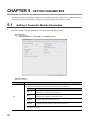
5.1
Setting C Controller Module Parameters . . . . . . . . . . . . . . . . . . . . . . . . . . . . . . . . . . . . . . . . . 56
5.1.1
5.2
C Controller module parameter item list. . . . . . . . . . . . . . . . . . . . . . . . . . . . . . . . . . . . . . . . . 57
Setting Network Parameters. . . . . . . . . . . . . . . . . . . . . . . . . . . . . . . . . . . . . . . . . . . . . . . . . . . 82
5.2.1
5.3
56
Network parameter item list . . . . . . . . . . . . . . . . . . . . . . . . . . . . . . . . . . . . . . . . . . . . . . . . . . 83
Setting Intelligent Function Module Parameter. . . . . . . . . . . . . . . . . . . . . . . . . . . . . . . . . . . . . 91
CHAPTER 6 SETTING C CONTROLLER MODULE CONNECTION DESTINATION 94
6.1
6.2
Setting Connection Destinations. . . . . . . . . . . . . . . . . . . . . . . . . . . . . . . . . . . . . . . . . . . . . . . . 94
6.1.1
Transfer setup screen . . . . . . . . . . . . . . . . . . . . . . . . . . . . . . . . . . . . . . . . . . . . . . . . . . . . . . 95
6.1.2
Creating connections . . . . . . . . . . . . . . . . . . . . . . . . . . . . . . . . . . . . . . . . . . . . . . . . . . . . . . . 97
6.1.3
Specifying connection destination for regular use . . . . . . . . . . . . . . . . . . . . . . . . . . . . . . . . . 98
Accessing C Controller Module Directly . . . . . . . . . . . . . . . . . . . . . . . . . . . . . . . . . . . . . . . . . . 99
6.2.1
Connecting with USB cable . . . . . . . . . . . . . . . . . . . . . . . . . . . . . . . . . . . . . . . . . . . . . . . . . . 99
6.2.2
Accessing by Ethernet . . . . . . . . . . . . . . . . . . . . . . . . . . . . . . . . . . . . . . . . . . . . . . . . . . . . . 100
6.3
Accessing C Controller Module in Multiple CPU System . . . . . . . . . . . . . . . . . . . . . . . . . . . . 102
6.4
Setting for Access via GOT (GOT Transparent Function) . . . . . . . . . . . . . . . . . . . . . . . . . . . 103
6.4.1
6.5
Accessing C Controller module via GOT . . . . . . . . . . . . . . . . . . . . . . . . . . . . . . . . . . . . . . . 103
Considerations of Communication with C Controller Module . . . . . . . . . . . . . . . . . . . . . . . . . 105
CHAPTER 7 WRITING/READING/VERIFYING DELETING PROJECT
106
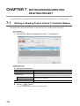
7.1
Writing or Reading Project to/from C Controller Module. . . . . . . . . . . . . . . . . . . . . . . . . . . . . 106
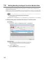
7.2
Writing/Reading Intelligent Function Module Data . . . . . . . . . . . . . . . . . . . . . . . . . . . . . . . . . 108
7.3
Verifying Data on C Controller Module against Data on Personal Computer . . . . . . . . . . . . . 111
7.4
Verifying Data on Intelligent Function Module against Data on Personal Computer . . . . . . . 112
7.5
Deleting C Controller Module Data . . . . . . . . . . . . . . . . . . . . . . . . . . . . . . . . . . . . . . . . . . . . . 113
CHAPTER 8 MONITORING
114
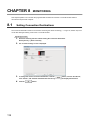
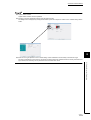
8.1
Setting Connection Destinations. . . . . . . . . . . . . . . . . . . . . . . . . . . . . . . . . . . . . . . . . . . . . . . 114
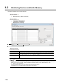
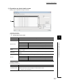
8.2
Monitoring Devices and Buffer Memory . . . . . . . . . . . . . . . . . . . . . . . . . . . . . . . . . . . . . . . . . 116
8.3
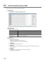
Monitoring Battery Backup RAM. . . . . . . . . . . . . . . . . . . . . . . . . . . . . . . . . . . . . . . . . . . . . . . 122
8.4
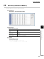
Monitoring Data Refresh Memory. . . . . . . . . . . . . . . . . . . . . . . . . . . . . . . . . . . . . . . . . . . . . . 125
8.5
Monitoring Intelligent Function Modules . . . . . . . . . . . . . . . . . . . . . . . . . . . . . . . . . . . . . . . . . 127
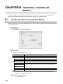
CHAPTER 9 OPERATING C CONTROLLER MODULE
9.1
134
Remote Operation of C Controller Module . . . . . . . . . . . . . . . . . . . . . . . . . . . . . . . . . . . . . . . 134
7
9.2
Setting Clock on C Controller Module. . . . . . . . . . . . . . . . . . . . . . . . . . . . . . . . . . . . . . . . . . . 136
CHAPTER 10 DIAGNOSING C CONTROLLER MODULE
137
10.1
Diagnosing C Controller Module. . . . . . . . . . . . . . . . . . . . . . . . . . . . . . . . . . . . . . . . . . . . . . . 137
10.2
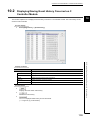
Displaying/Saving Event History Occurred on C Controller Module . . . . . . . . . . . . . . . . . . . . 139
10.3
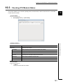
Checking CPU Module Status . . . . . . . . . . . . . . . . . . . . . . . . . . . . . . . . . . . . . . . . . . . . . . . . 141
10.4
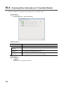
Checking Drive Information of C Controller Module . . . . . . . . . . . . . . . . . . . . . . . . . . . . . . . . 142
10.5
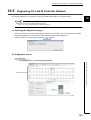
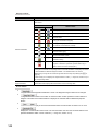
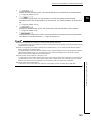
Diagnosing CC-Link IE Controller Network. . . . . . . . . . . . . . . . . . . . . . . . . . . . . . . . . . . . . . . 143
10.5.1 Communication test . . . . . . . . . . . . . . . . . . . . . . . . . . . . . . . . . . . . . . . . . . . . . . . . . . . . . . . 147
10.5.2 Link start/stop. . . . . . . . . . . . . . . . . . . . . . . . . . . . . . . . . . . . . . . . . . . . . . . . . . . . . . . . . . . . 148
10.5.3 Logging . . . . . . . . . . . . . . . . . . . . . . . . . . . . . . . . . . . . . . . . . . . . . . . . . . . . . . . . . . . . . . . . 150
10.6
Diagnosing CC-Link IE Field Network . . . . . . . . . . . . . . . . . . . . . . . . . . . . . . . . . . . . . . . . . . 152
10.6.1 Communication test . . . . . . . . . . . . . . . . . . . . . . . . . . . . . . . . . . . . . . . . . . . . . . . . . . . . . . . 157
10.6.2 Cable test . . . . . . . . . . . . . . . . . . . . . . . . . . . . . . . . . . . . . . . . . . . . . . . . . . . . . . . . . . . . . . . 158
10.6.3 Link start/stop. . . . . . . . . . . . . . . . . . . . . . . . . . . . . . . . . . . . . . . . . . . . . . . . . . . . . . . . . . . . 159
10.6.4 Network event history. . . . . . . . . . . . . . . . . . . . . . . . . . . . . . . . . . . . . . . . . . . . . . . . . . . . . . 160
10.6.5 Reserved station function enable. . . . . . . . . . . . . . . . . . . . . . . . . . . . . . . . . . . . . . . . . . . . . 162
10.6.6 Temporary error invalid station setting/restore . . . . . . . . . . . . . . . . . . . . . . . . . . . . . . . . . . . 163
10.7
Diagnosing MELSECNET. . . . . . . . . . . . . . . . . . . . . . . . . . . . . . . . . . . . . . . . . . . . . . . . . . . . 164
10.7.1 Network test . . . . . . . . . . . . . . . . . . . . . . . . . . . . . . . . . . . . . . . . . . . . . . . . . . . . . . . . . . . . . 166
10.7.2 Loop test . . . . . . . . . . . . . . . . . . . . . . . . . . . . . . . . . . . . . . . . . . . . . . . . . . . . . . . . . . . . . . . 168
10.7.3 Setting verification test . . . . . . . . . . . . . . . . . . . . . . . . . . . . . . . . . . . . . . . . . . . . . . . . . . . . . 169
10.7.4 Station order check test . . . . . . . . . . . . . . . . . . . . . . . . . . . . . . . . . . . . . . . . . . . . . . . . . . . . 171
10.7.5 Communication test . . . . . . . . . . . . . . . . . . . . . . . . . . . . . . . . . . . . . . . . . . . . . . . . . . . . . . . 172
10.7.6 Error history monitoring . . . . . . . . . . . . . . . . . . . . . . . . . . . . . . . . . . . . . . . . . . . . . . . . . . . . 174
10.7.7 Network monitor details . . . . . . . . . . . . . . . . . . . . . . . . . . . . . . . . . . . . . . . . . . . . . . . . . . . . 176
10.7.8 Monitoring other station information. . . . . . . . . . . . . . . . . . . . . . . . . . . . . . . . . . . . . . . . . . . 177
10.8
Diagnosing CC-Link and CC-Link/LT . . . . . . . . . . . . . . . . . . . . . . . . . . . . . . . . . . . . . . . . . . . 179
10.8.1 Monitoring line (host station/other stations) . . . . . . . . . . . . . . . . . . . . . . . . . . . . . . . . . . . . . 179
10.8.2 Loop test/transmission speed test . . . . . . . . . . . . . . . . . . . . . . . . . . . . . . . . . . . . . . . . . . . . 184
10.8.3 Displaying logs of station information (status logging) . . . . . . . . . . . . . . . . . . . . . . . . . . . . . 185
10.8.4 Creating check sheets . . . . . . . . . . . . . . . . . . . . . . . . . . . . . . . . . . . . . . . . . . . . . . . . . . . . . 187
10.8.5 Starting/stopping data link . . . . . . . . . . . . . . . . . . . . . . . . . . . . . . . . . . . . . . . . . . . . . . . . . . 189
10.9
Checking System Status and Error History. . . . . . . . . . . . . . . . . . . . . . . . . . . . . . . . . . . . . . . 190
10.9.1 Checking module's detailed information. . . . . . . . . . . . . . . . . . . . . . . . . . . . . . . . . . . . . . . . 196
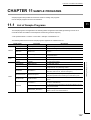
CHAPTER 11 SAMPLE PROGRAMS
197
11.1
List of Sample Programs . . . . . . . . . . . . . . . . . . . . . . . . . . . . . . . . . . . . . . . . . . . . . . . . . . . . 197
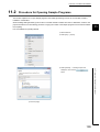
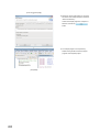
11.2
Procedure for Opening Sample Programs . . . . . . . . . . . . . . . . . . . . . . . . . . . . . . . . . . . . . . . 199
CHAPTER 12 TROUBLESHOOTING
201
APPENDIX
202
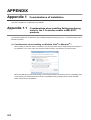
Appendix 1 Considerations of Installation . . . . . . . . . . . . . . . . . . . . . . . . . . . . . . . . . . . . . . . . . . . . 202
8
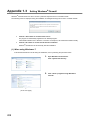
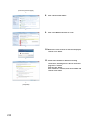
Appendix 1.1
Considerations when installing Setting/monitoring tools for the C Controller
module or MELSOFT products . . . . . . . . . . . . . . . . . . . . . . . . . . . . . . . . . . 202
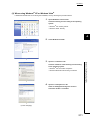
Appendix 1.2
USB driver installation . . . . . . . . . . . . . . . . . . . . . . . . . . . . . . . . . . . . . . . . 205
Appendix 1.3
Setting Windows® Firewall . . . . . . . . . . . . . . . . . . . . . . . . . . . . . . . . . . . . . 208
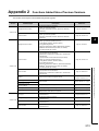
Appendix 2 Functions Added Since Previous Versions . . . . . . . . . . . . . . . . . . . . . . . . . . . . . . . . . . 213
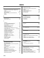
INDEX
214
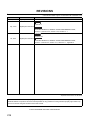
REVISIONS . . . . . . . . . . . . . . . . . . . . . . . . . . . . . . . . . . . . . . . . . . . . . . . . . . . . . . . . . . . . . . . . . . . . . . 216
9
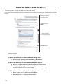
HOW TO READ THIS MANUAL
The following explains the page composition and symbols in this manual.
The content of the example page used here are different from the actual content for the intention of explaining how to use this
manual.
Indicates the chapter of
currently open page.
Remark indicates the
useful tip.
Indicates the section
of currently open page.
indicates the
particular attention.
Operating procedure
Three types of descriptions are used in this manual as below:
(1) When the operation is performed with a single step
•
Select [Project] ⇒ [Intelligent Function Module] ⇒ [New Module].
(2) When the operation is performed with multiple steps
1.
2.
Select the intelligent function module to be deleted from the Project view.
Select [Project] ⇒ [Intelligent Function Module] ⇒ [Delete Module].
The selected intelligent function module is deleted.
(3) When the operation can be performed by more than one method
•
•
10
Select "Project" menu ⇒ "Intelligent Function Module".
Select Project view ⇒ "Intelligent Function Module".
The following shows the symbols for the operations used in this manual.
Symbol
[
]
"
"
<<
>>
Description
Menu name on a menu bar
Screen name, item name on a
screen
Tab name on a screen
Example
[Diagnostics]
"parameter"
<<Multiple CPU Setting>>
Button on a screen
Keyboard key
Reference page
–
Reference manual
–
11
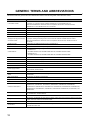
GENERIC TERMS AND ABBREVIATIONS
This manual uses the generic terms and abbreviations listed in the following table unless otherwise noted.
Generic term/abbreviation
Description
Generic term for Q24DHCCPU-V and Q24DHCCPU-LS
C Controller module
In principle, 'C Controller module' indicates Q24DHCCPU-V and Q24DHCCPU-LS.
When the classification is needed for such as comparison with other C Controller modules,
'Q24DHCCPU-V' and 'Q24DHCCPU-LS' is mentioned.
Q24DHCCPU-V
Abbreviation for Q24DHCCPU-V C Controller module
Q24DHCCPU-LS
Abbreviation for Q24DHCCPU-LS C Controller module
Q12DCCPU-V
Abbreviation for Q12DCCPU-V C Controller module
C Controller system
Generic term for the system where the C Controller module is mounted
Setting/monitoring tools for the C
In principle, 'Setting/monitoring tools for the C Controller module' indicates SW4PVC-CCPU.
Controller module
When the classification is needed for such as comparison with other tools, 'SW4PVC-CCPU' is
SW3PVC-CCPU
Abbreviation for Setting/monitoring tools for Q12DCCPU-V
VxWorks
Product name of the real-time operating system manufactured by Wind River Systems, Inc.
Abbreviation for Setting/monitoring tools for the C Controller module (SW4PVC-CCPU)
mentioned.
Generic term for the engineering tools for C Controller shown below
• Q12DCCPU-V
CW Workbench
SW1DND-CWWLQ12-E, SW1DND-CWWLQ12-EZ, SW1DND-CWWLQ12-EVZ
• Q24DHCCPU-V
SW1DND-CWWLQ24-E, SW1DND-CWWLQ24-EZ, SW1DND-CWWLQ24-EVZ
Q series
Abbreviation for Mitsubishi programmable controllers, MELSEC-Q series
L series
Abbreviation for Mitsubishi programmable controllers, MELSEC-L series
AnS series
Abbreviation for Mitsubishi programmable controllers, compact MELSEC-A series
Base unit
Generic term for the main base unit and extension base unit.
Extension cable
Power supply module
CPU module
QCPU
Basic model QCPU
Generic term for QC05B, QC06B, QC12B, QC30B, QC50B, and QC100B extension cables
Generic term for Q series power supply module Q61P-A1, Q61P-A2, Q61P, Q61P-D, Q62P, Q63P,
Q64P, Q64PN, Q63RP, Q64RP
Generic term for C Controller module, QCPU, and Motion CPU
Generic term for Basic model QCPU, High Performance model QCPU, Process CPU, and Universal
model QCPU
Generic term for Q00CPU and Q01CPU
High Performance model QCPU
Generic term for Q02CPU, Q02HCPU, Q06HCPU, Q12HCPU, and Q25HCPU
Process CPU
Generic term for Q02PHCPU, Q06PHCPU, Q12PHCPU, and Q25PHCPU
Generic term for Q00UJCPU, Q00UCPU, Q01UCPU, Q02UCPU, Q03UDCPU, Q04UDHCPU,
Q06UDHCPU, Q10UDHCPU, Q13UDHCPU, Q20UDHCPU, Q26UDHCPU, Q03UDECPU,
Universal model QCPU
Q04UDEHCPU, Q06UDEHCPU, Q10UDEHCPU, Q13UDEHCPU, Q20UDEHCPU, Q26UDEHCPU,
Q50UDEHCPU, Q100UDEHCPU, Q03UDVCPU, Q04UDVCPU, Q06UDVCPU, Q13UDVCPU, and
Q26UDVCPU
Motion CPU
I/O module
Intelligent function module
Multiple CPU system
Control CPU
12
Generic term for Mitsubishi Motion Controller Q172DCPU, Q173DCPU, Q172DCPU-S1, Q173DCPUS1, Q172DSCPU, and Q173DSCPU
Generic term for MELSEC-Q series and AnS series I/O modules
Generic term for MELSEC-Q series and AnS series module which have functions other than input and
output, such as an A/D or D/A converter module
Control system where multiple CPU modules are mounted on the main base unit
CPU module that controls I/O modules and intelligent function modules mounted on the main base unit
and extension base units
I/O module and intelligent function module controlled by a control CPU.
For example, if a module that is mounted to slot No. 3 is controlled by programmable controller CPU
Controlled module
No. 2, programmable controller CPU No. 2 is the control CPU of slot No. 3, and the module of slot No. 3
is the controlled module of programmable controller CPU No. 2.
Generic term for the CC-Link IE Controller Network module, MELSECNET/H module, CC-Link IE Field
Network module
Network module and CC-Link module
CC-Link IE Controller Network
module
MELSECNET/H module
CC-Link IE Field Network
master/local module
Generic term for the CC-Link IE Controller Network module QJ71GP21-SX, QJ71GP21S-SX
Generic term for the MELSECNET/H network module QJ71LP21-25, QJ71LP21S-25, QJ71LP21G,
QJ71LP21GE, QJ71BR11
Generic term for the CC-Link IE Field Network master/local module QJ71GF11-T2
Generic term for the CC-Link system master/local module QJ61BT11N, QJ61BT11, and CC-Link/LT
CC-Link module
master module QJ61CL12
Ethernet board
Generic term for Ethernet cards for personal computer and Ethernet interface boards
GOT
Abbreviation for the Mitsubishi Graphic Operation Terminal
GX Configurator-QP
The product name of the software package for MELSEC programmable controllers
Gateway function
Abbreviation for communication with programmable controller CPU and third-party programmable
communication
controllers using the gateway functions of GOT
MEANINGS AND DEFINITIONS OF TERMS
The terms used in this manual have the following meanings and definitions.
Term
Dedicated function library
Description
Generic term for Bus interface function, MELSEC data link function, and C Controller modulededicated function
Dedicated function library offered by C Controller module
This function is used when executing the following:
Bus interface function
• Input from or output to I/O modules controlled by the C Controller module
• Access to the buffer memory of an intelligent function module
• The readout or control of the C Controller module status
Dedicated function library offered by C Controller module
MELSEC data link function
This function is used when writing to/reading from a device of other programmable
Controller CPUs connected via network or configured with multiple CPUs.
C Controller modulededicated function
SD memory card
Dedicated function library that controls C Controller module
This function is used when reading the C Controller module status, controlling LED, and
accessing to resources such as time and battery backup RAM.
The memory card that satisfies the SD Association standards
13
CHAPTER 1
OVERVIEW
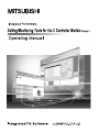
Setting/monitoring tools for the C Controller module is the software package that is installed to a personal computer
and connected to the C Controller module.
This chapter explains the overview of Setting/monitoring tools for the C Controller module.
1.1
Product Overview
Setting/monitoring tools for the C Controller module is the software package dedicated to parameter settings and
monitoring of C Controller module.
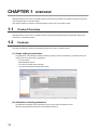
1.2
Features
This section explains the features of Setting/monitoring tools for the C Controller module.
(1) Simple setting of parameters
The parameters of C Controller module and following network modules controlled by C Controller module can
simply be set on the GUI screen of Windows®.
• CC-Link module
• MELSECNET/H module
• CC-Link IE Controller Network module
• CC-Link IE Field Network master/local module
(2) Utilization of existing parameters
The parameter setting files saved in SW3PVC-CCPU can be read from SW4PVC-CCPU.
Utilizing existing parameters improves the development efficiency.
14
CHAPTER 1 OVERVIEW
1
(3) Simple diagnose of C Controller system condition
The condition of C Controller module and following network modules controlled by C Controller module can
simply be diagnosed on the GUI screen of Windows®.
• CC-Link module
• MELSECNET/H module
• CC-Link IE Controller Network module
• CC-Link IE Field Network master/local module
1.2 Features
(4) Simple monitoring of device/buffer memory
The device/buffer memory of access target (programmable controller CPU/C Controller module) can simply be
monitored on the GUI screen of Windows®.
15
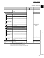
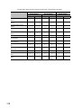
1.3
List of Functions
This section shows the list of functions of Setting/monitoring tools for the C Controller module.
:Supported, ¯:Not supported
CPU module
Project
Q24
Q24
Reference
DHC-V DHC-LS
New
Create a new project.
Page 38, Section 4.2.1
Open
Open an existing project.
Page 39, Section 4.2.2
Close
Close the open project.
Page 46, Section 4.2.6
Save
Save the project.
Save As
Name and save the project.
Page 41, Section 4.2.3
Compress/Unpack(M)
–
Compress
Compress and save a project.
Unpack
Decompress a compressed project.
Page 43, Section 4.2.4
Delete
Delete an existing project.
Page 46, Section 4.2.5
Verify
Verify between two project data.
Page 47, Section 4.2.7
Change CPU Type
Change the CPU type.
Page 49, Section 4.2.8
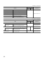
New
Add data to the project.
Page 50, Section 4.3.1
Rename
Rename the selected data.
Page 52, Section 4.3.3
Delete
Delete the selected data.
Page 52, Section 4.3.4
Copy
Copy the selected data.
Paste
Paste the copied data.
Object
Set as Default Connection
Property
–
Specify data in selected connection destination as
a connection destination for regular use.
Display the selected data properties.
Intelligent Function Module
New Module
Delete Module
Property
16
Page 53, Section 4.3.5
Delete intelligent function module.
Set the properties of the intelligent function
module.
Display a list of set parameters of all the
intelligent function modules.
Open Another Format Data
Exit
Page 98, Section 6.1.3
Page 91, Section 5.3
Parameter List
(Recently used files 1 to 4)
Page 51, Section 4.3.2
Add new intelligent function module.
Intelligent Function Module
Open Parameter Setting File
Page 91, Section 5.3 (1)
–
Open parameter setting file created with
SW3PVC-CCPU.
Display the recently used project paths and open
the selected project.
Exit Setting/monitoring tools for the C Controller
module.
Page 54, Section 4.4
–
Page 23, Section 3.1
CHAPTER 1 OVERVIEW
:Supported, ¯:Not supported
1
CPU module
Edit
Undo
Restore the previous processing status.
Redo
Restore the processing deleted with [Undo].
Cut
Cut the selected data.
Copy
Copy the selected data.
Paste
Paste the cut or copied data at the cursor position.
Q24
Q24
DHC-V
DHC-LS
Reference
–
:Supported, ¯:Not supported
CPU module
View
Q24
Q24
Reference
DHC-V DHC-LS
Toolbar
–
Toolbar name
Statusbar
Display/hide each toolbar.
Page 25, Section 3.2.2
Display/hide the status bar.
Page 35, Section 3.2.6
Docking Window
Navigation Window
Display/hide the Navigation window.
Intelligent Function Module Monitor
Intelligent Function
Display/hide the Intelligent Function Module Monitor
Module Monitor 1 to 10
window.
–
Page 34, Section 3.2.5
–
Page 91, Section 5.3
1.3 List of Functions
17
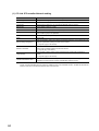
:Supported, ¯:Not supported
CPU module
Online
Q24
Q24
Reference
DHC-V DHC-LS
Read from CCPU
Write to CCPU
Verify with CCPU
Delete CCPU Data
Read data from the C Controller module/intelligent
function module.
Page 106, Section 7.1
Write data to the C Controller module/intelligent
Page 108, Section 7.2
function module.
Verify a project being edited against the data on the
Page 111, Section 7.3
C Controller module/intelligent function module.
Page 112, Section 7.4
Delete data on the C Controller module.
Page 113, Section 7.5
Remotely control RUN/PAUSE/STOP/RESET of the
Remote Operation
C Controller module from Setting/monitoring tools for
Page 134, Section 9.1
the C Controller module.
Set Clock
Device Monitor
Set the clock on the C Controller module.
Page 136, Section 9.2
Start monitoring the device. (Monitoring for multiple
Page 114, Section 8.1
devices can be started.)
Battery Backup RAM Monitor
Monitor the battery backup RAM.
Page 122, Section 8.3
Data Refresh Memory Monitor
Monitor the data refresh memory.
Page 125, Section 8.4
Start Watching
Start monitoring the intelligent function module.
Page 127, Section 8.5
Stop Watching
Stop monitoring the intelligent function module.
Watch
Login
Logout
Enter the user name and the password of account,
Page 76, Section 5.1 (10)
and log in to the C Controller module.
Log out from the C Controller module.
–
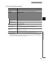
:Supported, ¯:Not supported
CPU module
Diagnostics
Q24
Q24
Reference
DHC-V DHC-LS
CCPU Diagnostics
Event History
Diagnose the operating status of the C Controller
Page 137, Section 10.1
module.
Display/save the event history occurred on the C
Controller module.
Page 139, Section 10.2
Check the operating status, switch status, and the
CPU Status
error that is currently occurring of the C Controller
Page 141, Section 10.3
module and CPU module.
Drive Information
CC IE Control Diagnostics
Display the drive information of the C Controller
module.
¯
Diagnose CC-Link IE Controller Network.
Page 142, Section 10.4
Page 143, Section 10.5
CC IE Field Diagnostics
Diagnose CC-Link IE Field Network.
Page 152, Section 10.6
MELSECNET Diagnostics
Diagnose MELSECNET/10(H).
Page 164, Section 10.7
CC-Link Diagnostics
Diagnose CC-Link and CC-Link/LT.
System Monitor
18
Monitor the system status of the C Controller
module.
Page 179, Section 10.8
Page 190, Section 10.9
CHAPTER 1 OVERVIEW
:Supported, ¯:Not supported
1
CPU module
Tool
Q24
Q24
DHC-V
DHC-LS
Reference
Specify the display range of QD75 positioning data
Options
and set the operation settings of QD75 positioning
Page 91, Section 5.3
module.
Intelligent Function Module Tool
Analog Module
Offset/Gain Setting
–
–
Configure the offset/gain setting of the analog
module.
Q61LD Two-Point
Perform the two-point calibration to use Q61LD as a
Calibration Setting
measuring device.
Q61LD Default Setting
Temperature Input Module
Offset/Gain Setting
Temperature Control
Module
Auto Tuning
Counter Module
Preset
Batch-restore the Q61LD parameters to the factory
default settings.
–
Configure the offset/gain setting of the temperature
input module.
GX Works2
–
Operating Manual
(Intelligent Function
Perform the automatic tuning of the temperature
control module.
–
Module)*1
Perform the preset function of counter module.
QD75 Positioning Module
Positioning Test
Wave Trace
Location Trace
Serial Communication
Module
Execute the positioning monitoring of QD75
1.3 List of Functions
Positioning Monitor
–
positioning module.
Perform the positioning test of QD75 positioning
module.
Perform the wave trace of QD75 positioning module.
Perform the location trace of QD75 positioning
module.
–
–
Trace the communication data and communication
Circuit Trace
control signals of the communication with the device
–
controller.
Request of Parameter
Initialize the buffer memory data and apply it to the
Initialization/Flush ROM Write
flash ROM.
Request
Write the buffer memory data to the flash ROM.
*1 :
Page 110, Section 7.2 (3)
The following functions are not supported by Setting/monitoring tools for the C Controller module.
• Wave output data creation of analog module
• Sensor correction function of temperature control module
• Predefined protocol support function of serial communication module
19
:Supported, ¯:Not supported
CPU module
Window
Cascade
Cascade windows.
Tile Vertically
Tile windows vertically.
Tile Horizontally
Tile windows horizontally.
Arrange Icons
Arrange the icons at the bottom of the window.
Close All
Close all open windows.
(Switch to other window)
Display the open window.
Window
Q24
Q24
DHC-V
DHC-LS
Reference
Page 27, Section 3.2.3
Display the list of open windows.
Also open or arrange specified windows.
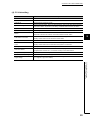
:Supported, ¯:Not supported
CPU module
Help
Q24
Q24
DHC-V
DHC-LS
Manual
–
Indicate Setting/Monitoring Tools for the C
(manual name)
Reference
Controller Module Operating Manual and
Page 36, Section 3.3.1
MELSEC-Q C Controller Module User's Manual.
Function Help
C Controller Module
Function Help
Version Information
20
–
Display the function help of Bus interface function,
MELSEC data link function, and C Controller
¯
Page 36, Section 3.3.2
module-dedicated function.
Check the version of Setting/monitoring tools for
the C Controller module.
Page 36, Section 3.3.3
CHAPTER 2 SYSTEM CONFIGURATION
CHAPTER 2
SYSTEM CONFIGURATION
2
This chapter explains the system configurations using C Controller module.
2.1
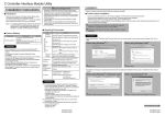
Connection from USB Port
The following shows the possible system configuration for connecting to the C Controller module using the USB port of
a personal computer.
• USB direct connection
• GOT (bus connection) via transparent
• GOT (Ethernet) via transparent
USB
Setting monitoring tools for
the C Controller module
Bus connection
USB
Ethernet
GOT
(transparent)
Personal computer for
development/maintenance
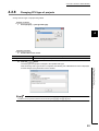
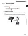
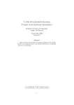
Connection from Ethernet Port
The following shows the system configuration for connecting to the C Controller module using the Ethernet board that
is built-in or installed on the personal computer.
• Ethernet direct connection
• GOT (bus connection) via transparent
Ethernet
Setting monitoring tools for
the C Controller module
Ethernet
Bus connection
GOT
(transparent)
Personal computer for
development/maintenance
C Controller module
21
2.1 Connection from USB Port
2.2
C Controller module
2.3
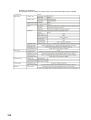
Modules connectable from USB port, Ethernet board
(1) Modules connectable from USB port
The following table shows the modules that can be connected from the USB port.
Series
Q series
*1 :
Module name
Module model
C Controller module
Q24DHCCPU-V, Q24DHCCPU-LS, Q12DCCPU-V*1
Programmable controller CPU module
Universal model QCPU*1
Connectable to Q24DHCCPU-V and Q24DHCCPU-LS on another station via Universal model QCPU or Q12DCCPU-V
in the multiple CPU system
(2) Modules connectable from Ethernet board
The following table shows the modules that can be connected from the Ethernet board.
I/F board model
Series
C Controller module
Ethernet board built-in a
personal computer or
commercially available
*1 :
*2 :
*3 :
22
Module name
Q series
Programmable controller CPU
module*3
Module model
Q24DHCCPU-V*2, Q24DHCCPU-LS*2,
Q12DCCPU-V*1
Built-in Ethernet port QCPU*1
Connectable to Q24DHCCPU-V and Q24DHCCPU-LS on another station via the Built-in Ethernet port QCPU or
Q12DCCPU-V in the multiple CPU system
Connectable from S CH1 only (cannot be connected from CH1, CH2)
Not connectable when the remote password is set on the programmable controller CPU
CHAPTER 3 SCREEN CONFIGURATION AND BASIC OPERATIONS
CHAPTER 3
SCREEN CONFIGURATION AND
BASIC OPERATIONS
This chapter explains the screen configuration and basic operations of Setting/monitoring tools for the C Controller
3
module.
3.1
Starting and Exiting
This section explains how to start/exit Setting/monitoring tools for the C Controller module.
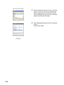
(1) Starting Setting/monitoring tools for the C Controller module
Start Setting/monitoring tools for the C Controller module.
Operating procedure
•
Select [Start] ⇒ [All Programs] ⇒ [MELSEC] ⇒ [Setting monitoring tools for the C Controller
module Ver.4] ⇒ [Setting/monitoring tools for the C Controller module].
Execution Prevention function (DEP) (Windows® security function).
When the 'mode' is "AlwaysOn", set another mode and restart the operating system.
For details of Data Execution Prevention function (DEP) and mode check/change, refer to Microsoft® support page.
● Setting/monitoring tools for the C Controller module can be executed by double-clicking a file (extension ".CP4" and
".CSC") created in Setting/monitoring tools for the C Controller module.
● Exiting Windows®
Windows® cannot be exited when Setting/monitoring tools for the C Controller module is running.
Exit Windows® after exiting Setting/monitoring tools for the C Controller module.
(2) Exiting Setting/monitoring tools for the C Controller module
Exit Setting/monitoring tools for the C Controller module.
Operating procedure
•
Select [Project] ⇒ [Exit].
23
3.1 Starting and Exiting
● When Setting/monitoring tools for the C Controller module cannot be executed, check the 'mode' of Windows® Data
3.2
Screen Configuration and Basic Operations
This section explains the main frame (basic screen) of Setting/monitoring tools for the C Controller module that is
displayed when it is started.
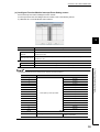
3.2.1
Main frame configuration
The following screen shows a main frame configuration on which a work window and docked windows are displayed.
Screen display
Title bar
Menu bar
Toolbar
Navigation
window
Work
window
Docking
window
Status bar
Display contents
Name
Description
Reference
Title bar
Display a project name.
–
Menu bar
Display menu options for executing each function.
–
Toolbar
Display tool buttons for executing each function.
Work window
Docking window
Navigation window
Status bar
A main screen used for operations such as parameter
setting, and monitoring.
A sub screen to support operations performed on a
work window.
Page 25, Section 3.2.2
Page 27, Section 3.2.3
Page 32, Section 3.2.4
Display contents of a project in tree format.
Page 34, Section 3.2.5
Display information about a project being edited.
Page 35, Section 3.2.6
● Focus point indication in Windows Vista® or Windows® 7
When using Windows Vista® or Windows® 7, the focus point may not be indicated on the screen.
To display the focus point, set the following setting.
For Windows Vista®, select [Start] ⇒ [Control Panel] ⇒ [Ease of Access] ⇒ [Ease of Access Center].
For Windows® 7, select [Start] ⇒ [Control Panel] ⇒ [Ease of Access Center].
Select "Make the keyboard easier to use".
Select "Underline keyboard shortcuts and access keys".
24
CHAPTER 3 SCREEN CONFIGURATION AND BASIC OPERATIONS
3.2.2
Toolbars
A toolbar is a block of on-screen buttons for executing frequently-used functions included in a menu.
(Page 202, Appendix 1)
The toolbars to be displayed and their display positions on the screen can be set by the user.
3
(1) Displaying/hiding toolbars
Select a toolbar to be displayed.
Operating procedure
•
Select [View] ⇒ [Toolbar] ⇒ [(toolbar name)].
The selected toolbar is displayed on the screen.
Toolbar
3.2 Screen Configuration and Basic Operations
3.2.2 Toolbars
25
(2) Docking/floating toolbars
Switch the display format (docked/floating) of a toolbar.
Operation
•
•
Drag a docked toolbar to the desired position for floating display.
Drag the title bar of a floating toolbar and drop it in the main frame.
Drag and drop
● Method for docking a toolbar at the original position
To dock a floating toolbar back at the original position, double-click on the title bar of the toolbar.
(3) Customizing toolbars
Set the types of tool buttons to be displayed on each toolbar.
Operating procedure
1.
Select the Toolbar options button (
) ⇒ [Add or Remove Buttons].
A list of tool buttons is displayed.
2.
Select the checkbox in front of the tool button to be displayed on the screen.
The selected tool buttons are displayed on the screen.
The toolbar configuration returns to the default when [Reset Toolbar] is selected.
26
CHAPTER 3 SCREEN CONFIGURATION AND BASIC OPERATIONS
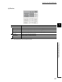
3.2.3
Work windows
A work window is a main screen used for operations such as programming, parameter setting, and monitoring in
Setting/monitoring tools for the C Controller module.
Screen display
Tab
3
Scroll button
Work window
switching button
Display windows
Item
Description
Become active when selected.
The tab order can be changed by dragging and dropping tabs.
The window(s) can be closed from the menu displayed by right-clicking the tab. In the other way, the
active window can be closed by clicking
on the tab.
Tab
Right-click
Tool hint
Scroll button
Display a brief explanation when the cursor is placed on the selected tab.
Scroll the tab display to the left and right.
Display hidden tabs.
Work window
Display the list of windows being displayed.
switching button
Select a data name displayed on the list to display its corresponding window on the top.
Display windows
Display screens such as parameter setting screen and monitoring screen.
27
3.2 Screen Configuration and Basic Operations
3.2.3 Work windows
Display contents
(1) Maximizing/minimizing screens
Maximize/minimize the screen size on the work window.
Operation
•
•
Click the Maximize button (
).
Click the Minimize button ( ).
● Restoring the screen size
Click
28
to return the maximized/minimized screen to its previous size.
CHAPTER 3 SCREEN CONFIGURATION AND BASIC OPERATIONS
(2) Arranging screens
Arrange screens to display on the work window.
(a) Cascading screens
Operation
•
3
Select [Window] ⇒ [Cascade].
(b) Tiling screens vertically
Operation
3.2 Screen Configuration and Basic Operations
3.2.3 Work windows
•
Select [Window] ⇒ [Tile Vertically].
29
(c) Tiling screens horizontally
Operation
•
Select [Window] ⇒ [Tile Horizontally].
(d) Arranging icons (minimized windows) at the bottom of the work window
Operation
•
30
Select [Window] ⇒ [Arrange Icons].
CHAPTER 3 SCREEN CONFIGURATION AND BASIC OPERATIONS
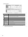
(3) Arranging/displaying windows
Display a list of open windows, and also open and arrange specified windows.
This function is useful to display the desired window efficiently when multiple windows are open.
Screen display
•
3
Select [Window] ⇒ [Window].
3.2 Screen Configuration and Basic Operations
3.2.3 Work windows
31
3.2.4
Docking windows
This section explains the operations common to docking windows.
(1) Displaying/Hiding dockable windows
Display/hide a dockable window.
Operating procedure
•
Select [View] ⇒ [Docking Window] ⇒ [(target item)].
(2) Docking/floating dockable windows
Switch the display format of a dockable window.
(a) Docked display
Display a dockable window docked to the main frame.
(b) Floating display
Display a dockable window floating from the main frame.
Operation
•
Drag the title bar of a floating dockable window and drop it to the guidance in the main frame.
Drag and drop
The docked window is floated by dragging the title bar to the desired position.
32
CHAPTER 3 SCREEN CONFIGURATION AND BASIC OPERATIONS
● Operation of dockable windows
Docked windows can be switched from docked to floating or vice versa by double-clicking the title bar.
Dockable display
3
Double-click
Double-click
Floating display
● Changing the tab order
The tab order can be changed by dragging and dropping the desired tab to the left or right when multiple dockable
windows are docked.
The tab order is changed.
Drag and drop
3.2 Screen Configuration and Basic Operations
3.2.4 Docking windows
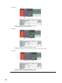
(3) Window minimized mode
Minimize a docked window as a tab.
The window minimized mode can be set and disabled by the following procedure.
Operating procedure
•
Click the window minimized mode switching icon (
/
).
Window minimized switching icon
Normal display
Docked window display in
window minimized mode
Window minimized mode
Only the tab is
displayed in
window
minimized mode.
Placing the cursor
on the tab displays
the window.
The window is displayed normally after
disabling window minimized mode.
33
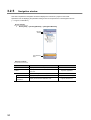
3.2.5
Navigation window
This section explains the Navigation window that displays the contents of a project in tree format.
Operations such as displaying the parameter setting screen can be performed on the Navigation window.
(Page 37, CHAPTER 4)
Screen display
•
Select [View] ⇒ [Docking Window] ⇒ [Navigation Window].
Title bar
Toolbar
View selection
area
Display contents
Name
Title bar
Toolbar
View selection area
Project
Connection
Destination
34
Description
Display a title of a view being displayed.
Display tool buttons of functions to be executed on
each view.
Area for selecting a view to display.
Display the Project view.
Display the Connection Destination view.
Reference
–
Page 202, Appendix 1
–
Page 38, Section 4.2.1 (1)
Page 95, Section 6.1.1
CHAPTER 3 SCREEN CONFIGURATION AND BASIC OPERATIONS
3.2.6
Status bar
The status bar displays information about the current project at the bottom of the screen.
Security information
CPU type
Connection destination
Caps
Num
Lock
Lock
3
The following shows the information to be displayed.
Item
Description
Security information
Display the current login user name of C Controller module.
CPU type
Display the CPU type of the project.
Connection destination
Display the set content of the "Transfer Setup" screen.
Caps Lock
Display the effective status of the Caps Lock.
Num Lock
Display the effective status of the Num Lock.
(1) Displaying/hiding status bar
Display/hide the status bar.
Operating procedure
•
Select [View] ⇒ [Statusbar].
A check mark is appended in front of the menu option and the status bar is displayed on the screen.
3.2 Screen Configuration and Basic Operations
3.2.6 Status bar
35
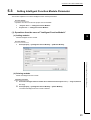
3.3
Help Function
This function displays such as method for using Bus interface function, MELSEC data link function, and C Controller
module-dedicated function.
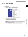
3.3.1
Displaying manuals
Display Setting/Monitoring Tools for the C Controller Module Operating Manual, MELSEC-Q C Controller Module
User's Manual.
Screen display
•
3.3.2
Select [Help] ⇒ [Manual] ⇒ [(manual name)].
Displaying function help
Display the detailed description of Bus interface function, MELSEC data link function, and C Controller modulededicated function.
Screen display
•
3.3.3
Select [Help] ⇒ [Function help] ⇒ [C Controller module function help].
Checking version of Setting/monitoring tools for the C
Controller module
Display information such as the software version of Setting/monitoring tools for the C Controller module.
Screen display
•
36
Select [Help] ⇒ [Version information].
CHAPTER 4 PROJECT MANAGEMENT
CHAPTER 4
PROJECT MANAGEMENT
This chapter explains basic operations and management of projects.
4.1
Configuration of Workspace/Project of Setting/
Monitoring Tools for the C Controller Module
The following explains the configuration of workspace/project of Setting/monitoring tools for the C Controller module.
4
<Data in the SW4PVC-CCPU data folder>
<Data in the Workspace 1 folder>
A folder specified for the save folder path when the project is saved.
A folder corresponds to the workspace name specified when the project is saved.
A folder corresponds to the project name specified when the project is saved.
A file created automatically when the project is saved.
A file created automatically when the project is saved.
37
4.1 Configuration of Workspace/Project of Setting/Monitoring Tools for the C Controller Module
Save destination folder
Workspace name folder
Project name folder
workspacelist.xml
projectlist.xml
4.2
Basic Operations of Project
This section explains basic operations of Setting/monitoring tools for the C Controller module such as creating,
opening, and saving projects.
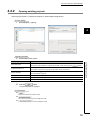
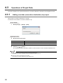
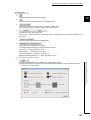
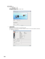
4.2.1
Creating projects
Create a new project.
Screen display
•
Select [Project] ⇒ [New].
Operating procedure
•
Set the items on the screen.
Item
CPU Type
Description
Select the CPU type used for the project.
● Creating new projects with parameters read from CCPU
A new project can be created with parameters read from a C Controller module when the Read from CCPU function is
executed without creating a new project. (Page 106, Section 7.1)
● Creating new projects
Do not change the storage location and names of folders/files of a created workspace/project using the application such
as Windows® Explorer.
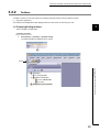
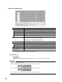
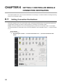
(1) Project view
Project contents displayed on the Project view in tree format are as shown below.
Set various parameters. Page 56, CHAPTER 5
38
CHAPTER 4 PROJECT MANAGEMENT
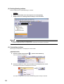
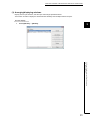
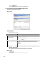
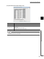
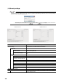
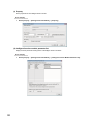
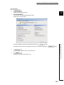
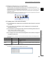
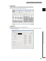
4.2.2
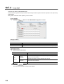
Opening existing projects
Read a project saved on a personal computer or another data storage device.
Screen display
•
Select [Project] ⇒ [Open].
4
Operating procedure
1.
Set the items on the screen.
Save Folder Path
Workspace/Project List
Display all folders
Description
Enter the folder (drive/path) where the workspace is saved.
The folder can be selected in the "Browse For Folder" screen by clicking the
Select the workspace or project.
The display is switched to the project list by double-clicking "Workspace".
Select this to display workspace folders and project folders copied/moved by the application
such as Windows® Explorer.
Workspace Name
Display the selected workspace name.
Project Name
Display the selected project name.
Title
Display the title of the selected project.
2.
Click the
button.
button.
The specified project is displayed.
Screen button
●
Displays the "Browse For Folder" screen
●
Switches to the Open screen in the single file format.
●
Switches to the Open screen in the workspace format.
39
4.2 Basic Operations of Project
4.2.2 Opening existing projects
Item
● Open screen
The Open screen with the initial setting opens a project in the single file format.
• If the file save destination path is long, the "Look in" field may be left blank when opening a project in the single file
format. Even with the blank field, the selected folder/file can be opened normally.
Switch the screen by clicking the
button to open the existing project in the workspace
format.
● Single file format
Single file format is a format to handle project files as a single file. By saving projects in the single file format, projects are
managed without being aware of the folder configuration and the file configuration, and operations such as: changing
project names, copying and pasting projects, and sending and receiving data, can easily be performed.
● Workspace
A workspace is a special folder of Setting/monitoring tools for the C Controller module dedicated to managing multiple
projects under the same name.
Do not change the workspace configuration using the application such as Windows® Explorer.
● Opening projects being edited by other users
The project being edited can be opened by other users as a read-only project. Note that the following function cannot be
used.
• Saving projects
40
CHAPTER 4 PROJECT MANAGEMENT
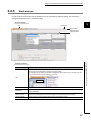
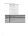
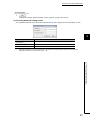
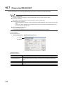
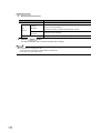
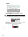
4.2.3
Saving projects
Save a project on a personal computer or another data storage device.
(1) Saving projects under the specified name
Save the open project under the specified name.
Screen display
•
Select [Project] ⇒ [Save As].
4
4.2 Basic Operations of Project
4.2.3 Saving projects
Operating procedure
1.
Set the items on the screen.
Item
Save Folder Path
Workspace/Project List
Description
Enter the folder (drive/path) where the workspace is saved.
The folder can be selected in the "Browse For Folder" screen by clicking the
Select the workspace or project.
The display is switched to the project list by double-clicking "Workspace".
Workspace Name
Enter the workspace name.
Project Name
Enter the project name.
Title
Enter the title of the project.
2.
Click the
button.
button.
The project is saved in the specified folder under the specified workspace name, project name, and title.
Screen button
●
Displays the "Browse For Folder" screen
●
Switches to the Save as screen in the single file format.
●
Switches to the Save as screen in the workspace format.
41
● Save As screen
The Save As screen with the initial setting saves a project in the single file format.
• If the file save destination path is long, the "Save in" field may be left blank when saving a project in the single file
format. Even with the blank field, the selected folder/file can be saved normally.
Switch the screen by clicking the
button to save the project in the workspace format.
● Single file format
Single file format is a format to handle project files as a single file. By saving projects in the single file format, projects are
managed without being aware of the folder configuration and the file configuration, and operations such as: changing
project names, copying and pasting projects, and sending and receiving data, can easily be performed.
● Workspace
A workspace is a special folder of Setting/monitoring tools for the C Controller module dedicated to managing multiple
projects under the same name.
Do not change the workspace configuration using the application such as Windows® Explorer.
● Saving projects in an existing destination
When saving the project in an existing destination (workspace or project), the destination folder can be selected from the
"Workspace/Project List".
● Number of characters used for workspace name, project name, and title
The total number of characters used for the workspace folder path, workspace name, and project name should not
exceed 200 characters.
A title can be entered within 128 characters.
(2) Saving projects
Overwrite and save the project being edited.
Operating procedure
•
Select [Project] ⇒ [Save].
The data to be saved is overwritten on the existing project data.
42
CHAPTER 4 PROJECT MANAGEMENT
4.2.4
Saving projects with compression/decompressing projects
Save projects with compression, and decompress projects saved with compression.
These functions produce easier project data passing.
These functions are not compatible with commercially available file compression and decompression tools.
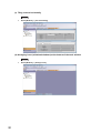
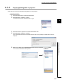
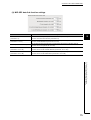
(1) Saving projects with compression
Save a desired project with compression.
4
Screen display
•
Select [Project] ⇒ [Compress/Unpack] ⇒ [Compress].
4.2 Basic Operations of Project
4.2.4 Saving projects with compression/decompressing projects
Operating procedure
1.
Set the items on the screen.
Item
Description
Project to be Compressed
Enter the folder (drive/path) where the workspace is saved.
Workspace Folder Path
The folder can be selected in the "Browse For Folder" screen by clicking the
Workspace/Project List
Select the workspace and project.
button.
Workspace Name
Display the selected workspace name.
Project Name
Display the selected project name.
Compress Destination Setting
Enter the folder where the compressed file is saved, and the compressed file name.
Compressed File Name
The compressed file name can be specified in the "Compressed File Name" screen
by clicking the
File is divided
button.
Select this to save data in multiple compressed files. Specify the split size in the
range from 1 to 999MB.
43
2.
Click the
button.
The compressed project file (*.csz) is saved in the specified folder.
(2) Decompressing projects saved with compression
Decompress a project saved with compression.
Screen display
•
Select [Project] ⇒ [Compress/Unpack] ⇒ [Unpack].
Operating procedure
1.
Set the items on the screen.
Item
Description
Unpack Source Setting
Enter the folder (drive/path) in which the compressed file to be decompressed is
Compressed File Name
saved, and the compressed file name.
The compressed file name can be specified in the "Compressed File Name" screen
by clicking the
button.
Unpack Destination Project
Enter the folder (drive/path) to which the project to be decompressed is saved.
Workspace Folder Path
The folder can be selected in the "Browse For Folder" screen by clicking the
button.
Workspace/Project List
Select the workspace and project.
Workspace Name
Enter the name of the workspace to which the decompressed project is saved.
Project Name
Enter the name of the project to which the decompressed project is saved.
2.
Click the
button.
The compressed project file is decompressed and saved in the specified folder.
Screen button
•
Decompresses a compressed project file and opens the project.
44
CHAPTER 4 PROJECT MANAGEMENT
● Decompressing compressed files
A compressed file can also be decompressed on the "Unpack" screen which is displayed by double-clicking the
compressed file (*.csz) on Windows® Explorer.
● Names of divided compressed files
When a project is saved in divided compressed files, a number is automatically added after the extension in each name
of the second or later compressed files as follows.
· · · · · · Name of the first file
4
· · · · · · Name of the second file
· · · · · · Name of the third file
· · · · · · Name of the fourth file
● Decompressing divided compressed files
Select the first file (*.csz) when decompressing a series of divided compressed files. To be decompressed, all of a series
of divided files must be in the same folder.
4.2 Basic Operations of Project
4.2.4 Saving projects with compression/decompressing projects
45
4.2.5
Deleting projects
Delete a project saved on a personal computer or another data storage device.
Screen display
•
Select [Project] ⇒ [Delete].
Operating procedure
1.
Select the project to be deleted.
2.
Click the
button.
The selected project is deleted.
● Deleting projects
• Once a project is deleted, it cannot be restored again.
• The open project cannot be deleted. Delete the project after closing it.
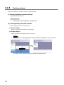
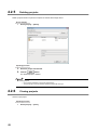
4.2.6
Closing projects
Close an open project.
Operating procedure
•
46
Select [Project] ⇒ [Close].
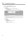
CHAPTER 4 PROJECT MANAGEMENT
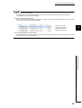
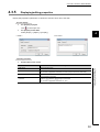
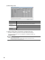
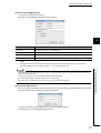
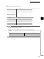
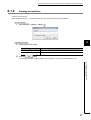
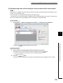
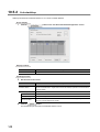
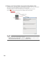
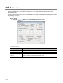
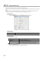
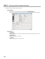
4.2.7
Verifying project data
Verify data of an open project against data of another project.
This function is used to compare the content of two projects or to locate program changes made in projects.
To verify data against parameters on the C Controller module, use the Verify with CCPU function.
(Page 111, Section 7.3)
Screen display
•
Select [Project] ⇒ [Verify].
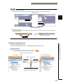
<<File Selection>> tab
4
<<Parameter>> tab
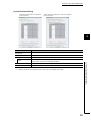
1.
Click the
button to set the verify destination project.
Item
2.
Description
Workspace Folder Path
Display the path to the workspace of the verify destination.
Verify Destination
Workspace Name
Display the workspace name of the verify destination.
Project
Project Name
Display the project name of the verify destination.
Title
Display the project title of the verify destination.
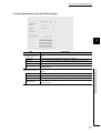
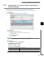
Select the verification target file on the <<File Selection>> tab.
Item
Description
CCPU/Network
Parameter
Intelligent Function Module
Select the verification target parameter.
(Initial Setting)
47
4.2 Basic Operations of Project
4.2.7 Verifying project data
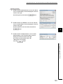
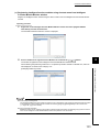
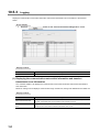
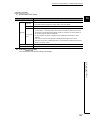
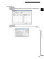
Operating procedure
3.
Select the parameter verification level on the <<Parameter>> tab.
The following table shows the verification details for each setting item.
Item
4.
Description
User Setting Area Only
Verify only the parameter area set by the user.
All Area
Verify all the area including the parameter area set by the system.
Click the
button.
The verification result is displayed on the "Verify Result" screen.
(Page 48, (1) in this section)
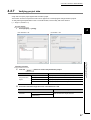
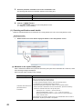
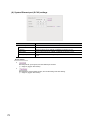
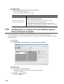
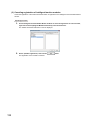
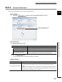
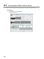
(1) Checking verification result details
Details of mismatched data can be checked in the <<Verify Result List>> tab on the "Verify Result" screen.
Operating procedure
•
Double-click the row of the data to display the details on the "Verify Result" screen.
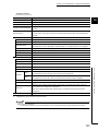
(a) Mismatch in the system setting area
When a mismatch is detected in the parameter area set by the system in the verification set to "All Area", either
of the following messages is displayed.
Take corrective action according to the message.
Message
Corrective action
A mismatch is detected in other than user setting area.
Take one of the following corrective actions.
• Reset the mismatch part of the parameter.
For block number (parameter number), refer to the following manual.
MELSEC-Q C Controller Module User's Manual
The header information of the
parameter blocks is
inconsistent.
• Rewrite the parameters having been written to the C Controller module.
When a mismatch is detected on the block number AFFF, perform the following
operation to reset the area which is set by the system.
• Select Project view ⇒ Parameter ⇒ Network Parameter ⇒
Ethernet/CCIE/MELSECNET. Click the
button on the displayed
MELSECNET/CCIE/Ethernet Module Configuration screen and write the parameters
to the C Controller module.
If the mismatch is not resolved, please consult your local Mitsubishi service center or
representative, explaining the details of the problem.
48
CHAPTER 4 PROJECT MANAGEMENT
4.2.8
Changing CPU type of projects
Change the CPU type of a project being edited.
Display contents
•
Select [Project] ⇒ [Change CPU Type].
4
Operating procedure
1.
Set the items on the screen.
Item
CPU Type
2.
Description
Select the CPU type after change.
Click the
button.
The items can be copied and pasted to the text file using the + and + keys.
49
4.2 Basic Operations of Project
4.2.8 Changing CPU type of projects
The CPU type of the project is changed to the specified CPU type.
After the Change CPU Type function is completed, the following List of Modifications screen is displayed,
and the changes of the parameters can be checked.
4.3
Operations of Project Data
This section explains how to operate data when the connection destination is selected on the Navigation window.
4.3.1
Adding new data (connection destination) to project
Add new data (connection destination) to a project.
The data that can be added is connection destination only.
Screen display
•
Select [Project] ⇒ [Object] ⇒ [New].
Operating procedure
1.
Set the items on the screen.
Item
Description
Data Name
Enter the name of the data to be created.
Set as Default Connection
Select this to specify the connection destination to be created for regular use.
2.
Click the
button.
The created connection destination is added to "All Connections" on the Connection Destination view.
● Maximum number of characters that can be entered for data name
The maximum number of characters that can be entered for data name is 32.
● Maximum number of data that can be created
The maximum number of data that can be created is 128.
50
CHAPTER 4 PROJECT MANAGEMENT
4.3.2
Copying/pasting data in projects
Utilize data of a connection destination being edited or in other projects.
Operating procedure
1.
2.
Select the data name of connection destination.
Select [Project] ⇒ [Object] ⇒ [Copy].
The selected connection destination data is copied.
4
3.
4.
Select the folder to paste the connection destination data.
Select [Project] ⇒ [Object] ⇒ [Paste].
If the same data name exists in the folder where the data is to be pasted, the "Data Paste" screen is
displayed.
Enter a new name in the "Data Name After Paste" field, and click the
4.3 Operations of Project Data
4.3.2 Copying/pasting data in projects
5.
button.
The connection destination data is pasted.
51
● Copying/pasting data
• Data can be pasted only to the data that is of the same type as copied data.
• Multiple data can be copied by holding the or key and selecting the data.
• Data can be copied/pasted by right-clicking data to be copied/folder to be pasted and selecting [Copy]/[Paste]
from the shortcut menu, or by dragging and dropping the data from the data to be copied to the folder to be
pasted.
• Copying and pasting only CCPU parameter or Network parameter are not possible. If it is copied individually, the
whole parameter files are copied and the files in the folder where the data is to be pasted are overwritten.
4.3.3
Changing project data names
Change the data name of open project.
Operating procedure
1.
2.
3.
4.
Select the data name to be changed on the Project view.
Select [Project] ⇒ [Object] ⇒ [Rename].
Change the data name.
Press the key.
The selected data name is changed.
4.3.4
Deleting project data
Delete data in an open project.
Operating procedure
1.
2.
Select the data name to be deleted on the Project view.
Select [Project] ⇒ [Object] ⇒ [Delete].
The selected data is deleted.
● Deleting data
• Multiple data can be selected and deleted.
52
CHAPTER 4 PROJECT MANAGEMENT
4.3.5
Displaying/editing properties
Display data properties of parameters. A title and/or comment can be set to each data.
Screen display
•
For property of project
Click
•
on the Project view.
For property of each data
Select [Project] ⇒ [Object] ⇒ [Property].
<<Detail>>
4
<<Comment>>
Operating procedure
•
Set the items on the screen.
Item
Title
Last Change
Display the data name.
4.3 Operations of Project Data
4.3.5 Displaying/editing properties
Data Name
Description
Set a title for the data.
(The number of applicable characters is 128 for a project and 32 for other data.)
Display the date when the data was updated.
Set a comment for the data.
Comment
Press the and the
keys for a line feed.
(The number of applicable characters is 5,120.)
53
4.4
Utilizing Parameters of Earlier Version
This section explains how to utilize parameter setting file created with SW3PVC-CCPU in SW4PVC-CCPU.
(1) Utilizing parameter setting files
The parameter setting files created with SW3PVC-CCPU can be utilized in SW4PVC-CCPU with
[Open parameter setting file].
(Page 55, (1)(a) in this section)
<SW3PVC-CCPU>
C Controller setting utility
parameter setting file
created with C Controller
setting utility
CC IE Control utility
<SW4PVC-CCPU>
parameter setting file
created with CC IE Control
utility
Open parameter setting file
MELSECNET_H utility
parameter setting file
created with
MELSECNET_H utility
CC-Link utility
parameter setting file
created with CC-Link utility
When the parameter setting files created with SW3PVC-CCPU is opened in SW4PVC-CCPU, only the parameters set on
each utility are applied to SW4PVC-CCPU. (When the parameters that are already set exist, the read parameters are
overwritten.)
54
CHAPTER 4 PROJECT MANAGEMENT
(a) Opening parameter setting files
Open the parameter setting files created with SW3PVC-CCPU in SW4PVC-CCPU.
Screen display
•
[Project] ⇒ [Open another format data] ⇒ [Open parameter setting file]
4
Operating procedure
•
Select the parameter setting file, and click the
button.
● Location to which the content of each parameter setting file is applied
The content of each parameter setting file is applied to the location shown in table below.
Parameter setting file of SW3PVC-CCPU
Setting/monitoring tools for the C Controller module
(File name: "*.cst")
Location to which SW4PVC-CCPU data is
applied.
CCPU parameter
CC IE Control utility (File name: "*.mng")*1
MELSECNET/H utility (File name: "*.mnh")
Network parameter
CC-Link utility (File name: "*.ccl")
*1 :
When parameters setting file of CC IE Control utility is opened, parameter settings of CC-Link IE Field Network on
SW4PVC-CCPU are overwritten.
55
4.4 Utilizing Parameters of Earlier Version
Select "*.cst", "*.mng", "*.mnh", "*.ccl" for a parameter setting file.
The content of selected parameter setting file is applied to the project.
CHAPTER 5
SETTING PARAMETERS
This chapter explains the setting items, operations on the setting screens, and common notes on parameter settings.
For necessary information and details of settings, refer to the manuals of each module to be used.
5.1
Setting C Controller Module Parameters
This section explains how to set parameters on the "CCPU parameter setting" screen.
Screen display
•
Select Project view ⇒ "Parameter" ⇒ "CCPU Parameter".
Display contents
Item
Description
The setting items are categorized under tabs according to their purpose.
• The parameter setting status is displayed by different font colors of the tab names.
Font color
Red
Tab
Blue
Setting status
Status that data is not set under the tab
(Data must be set under the tab for operation.)
Status that data is set under the tab
(A red tab name changes to blue after data is set.)
Magenta
Default values
(The user setting has not set under the tab.)
Dark blue
Values other than default values
(A magenta tab name changes to dark blue after data is set.)
• For details of the setting items, refer to the following section.
Page 57, Section 5.1.1
56
CHAPTER 5 SETTING PARAMETERS
Screen button
•
Resets all setting items on the screen being open to their defaults.
•
Checks whether the user-set parameters on the screen being open are correct.
5.1.1
C Controller module parameter item list
The following shows the list of CCPU parameter setting items.
For details of each item, refer to the following manual.
MELSEC-Q C Controller Module User's Manual
Setting tab name
5
Reference
Name settings
Page 57, (1) in this section
System settings
Page 58, (2) in this section
RAS settings
Page 60, (3) in this section
Device settings
Page 61, (4) in this section
I/O Assignment settings
Page 62, (5) in this section
Multiple CPU settings
Page 67, (6) in this section
User Ethernet port (CH1 and CH2)
settings
System Ethernet port (S CH1) settings
Page 71, (7) in this section
Page 72, (8) in this section
Page 75, (9) in this section
Account settings
Page 76, (10) in this section
Data refresh settings
Page 78, (11) in this section
Security settings
Page 80, (12) in this section
(1) Name settings
Item
Description
Label
Set a label (name and application) of the C Controller module. (Maximum of 10 characters)
Comment
Set a comment for the C Controller module. (Maximum of 64 characters)
57
5.1 Setting C Controller Module Parameters
5.1.1 C Controller module parameter item list
MELSEC data link function settings
(2) System settings
Set to use the C Controller module.
Item
Points Occupied by Empty Slot*1
Remote Reset
Allow
1024) for the main base unit/extension base unit.
–
Select this to allow a remote reset operation from Setting/monitoring tools for the C Controller
module.
Output Mode at STOP to RUN
Set the status of output (Y) when the programmable controller is switched from STOP to RUN.
Refresh setting
Set the refresh cycle (0, 10 to 2000ms).*2
Intelligent Function Module
Setting
Module Synchronization
button.
(Page 59, (2)(a) in this section)
–
Select this to synchronize the start-up of the C Controller module with that of the intelligent
module's pulse up
function module.
Allow
Standard RAM settings*3
*1 :
*2 :
*3 :
Display "Intelligent Function Module Interrupt Event Setting" screen by clicking the
Synchronize intelligent
Restart user CPU
58
Description
Set the number of points occupied by empty slots (select from 0, 16, 32, 64, 128, 256, 512,
–
Select this to allow restarting the user CPU.
–
Use
Select this to use standard RAM.
Capacity
Set the capacity of standard RAM (1 to 4MB).
Settings of each CPU are required to be the same ones in the multiple CPU system.
The refresh function is not executed when '0' is specified.
Not supported by Q24DHCCPU-LS.
CHAPTER 5 SETTING PARAMETERS
(a) Intelligent Function Module Interrupt Event Setting screen
Set the interrupt event data of intelligent function module.
For interrupt events from the intelligent function module, refer to the following manual.
MELSEC-Q C Controller Module User's Manual
5
Item
Description
CPU Side
-
interrupt event
Set the start number of the interrupt event occurred by interruption from the intelligent function
Start No.
module (50 to 255).
interrupt event Count
Intelligent Module Side
Set the number of the interrupt events occurred by interruption from the intelligent function
module (1 to 16).
-
Start I/O No.
Set the start I/O number of the intelligent function module (0000H to 0FF0H, 3E00H to 3E30H).
Start SI No.
Set the start SI number of the intelligent function module (1 to 15).
5.1 Setting C Controller Module Parameters
5.1.1 C Controller module parameter item list
The following shows the list for interrupt event numbers and interrupt factors.
Interrupt event No.
Interrupt factor
0
1st point
1
2nd point
2
3rd point
3
4th point
4
5th point
5
6th point
6
7th point
7
8
8th point
Interruption by interrupt module
9th point
9
10th point
10
11th point
11
12th point
12
13th point
13
14th point
14
15th point
15
16 to 49
50 to 255
16th point
Not used
Intelligent function module interrupt
Specify which intelligent function module
is used in parameters.
59
(3) RAS settings
Item
WDT (Watchdog Timer) Setting
System WDT setting
Monitoring time
User WDT Setting*1
Set the values relating to system WDT (Watch dog timer).
Set the monitoring time of system WDT (Watch dog timer) (20 to 2000).
Set the values relating to user WDT (Watch dog timer).
Select this to use user WDT (Watch dog timer).
Monitoring time
Set the monitoring time of user WDT (Watch dog timer) (100 to 10000).
–
Carry Out Battery Check
Select this to detect a battery error.
Carry Out Fuse Blown Check
Select this to detect a fuse blow
Verify Module
Select this to detect an I/O module verification error.
Diagnose Redundant Power
Supply System
Operation mode at the time of error
Fuse blown
Module verify error
Event history registration settings
Do not register system
(information) event details.
60
–
Use user WDT
Error check
*1 :
Description
Not supported by Q24DHCCPU-LS.
Select this to detect a redundant power supply module fault.
–
Select this for the operation (stop/continue) when a fuse blow is detected.
Select this for the operation (stop/continue) when a module verification error is
detected.
–
Select this when a system (information) event is not registered to event history.
CHAPTER 5 SETTING PARAMETERS
(4) Device
Item
Device Points*1 *2
Internal Relay
*1 :
*2 :
–
Set the number of points (0 to 60K) used for internal relay (M).
Link Relay
Set the number of points (0 to 640K) used for link relay (B).
Data Register
Set the number of points (0 to 4086K) used for data register (D).
Link Register
Set the number of points (0 to 1024K) used for link register (W).
Device Total
5
Description
Display the total size of the set devices.
Word Device
Display the size of the set word devices.
Bit Device
Display the size of the set bit devices.
Set in units of words.
For bit device (M, B), count 16 points as one point.
5.1 Setting C Controller Module Parameters
5.1.1 C Controller module parameter item list
61
(5) I/O Assignment
Item
I/O Assignment
Description
*1
–
The slot number and what number of the slot on what number of the stage are displayed for each slot.
Slot
When the base unit is set in the Auto mode, "*" indicates the base unit stage number and the slot
number counted from slot 0 of the main base unit is displayed
Type
Set the type of module being mounted.
Model Name*2
Set the mounted module model name. (Maximum of 16 characters)
Points
Set the points of each slot (select from 0, 16, 32, 64, 128, 256, 512, 1024).
Start XY
Set the start I/O number of each slot.
Base
Setting*1
Base Model
–
Name*2
Power Model Name*2
Extension Cable
Slots
Base Mode*3
*1 :
*2 :
*3 :
62
*2
Set the model name of the used main base unit or extension base unit. (Maximum of 16 characters)
Set the model name of the power supply module mounted on the main base unit or extension base
unit. (Maximum of 16 characters)
Set the extension cable model name. (Maximum of 16 characters)
Set the number of slots of the main base unit or extension base unit (select from 2, 3, 5, 8, 10, 12).
Set the number of slots for all base units.
Set the base mode.
Settings of each CPU are required to be the same ones in the multiple CPU system.
C Controller module does not use the specified model name. (It is used as a user's memo or for parameter printing)
For the base mode, refer to the following manual.
MELSEC-Q C Controller Module User's Manual
CHAPTER 5 SETTING PARAMETERS
Screen button
•
Opens the "Switch Settings for I/O and Intelligent Function Module" screen.
(Page 65, (5)(a) in this section)
•
Opens the "Intelligent Function Module Detailed Settings" screen.
(Page 66, (5)(b) in this section)
•
Batch-sets each base unit to 8 slots.
•
Batch-sets each base unit to 12 slots.
5
•
(Page 66, (5)(c) in this section)
The following shows the setting example of "Type" and "Points" for I/O assignment of CPU mounting slot.
<Example 1>
5.1 Setting C Controller Module Parameters
5.1.1 C Controller module parameter item list
No.1
• Set "No. of CPU" on the <<Multiple CPU Setting>> tab to 1.
• Set Type to "Empty", Points to "0 Point" for No.1 and No.2.
<Example 2>
No.1
No.4
• Set "No. of CPU" on the <<Multiple CPU Setting>> tab to 4.
• Set Type to "CPU(Empty)" for No.1 and No.2.
63
<Example 3>
No.1
No.2
• Set "No. of CPU" on the <<Multiple CPU Setting>> tab to 4.
• Set Type to "CPU(Empty)" for No.2 and No.3.
<Example 4>
No.1 No.2
No.3
• Set "No. of CPU" on the <<Multiple CPU Setting>> tab to 4.
• Set Type to "CPU(Empty)" for No.3, and set Type to "Empty", Points to "0 Point" for No.4.
<Example 5>
No.1 No.2 No.3
No.4
• Set "No. of CPU" on the <<Multiple CPU Setting>> tab to 4.
• Set Type to "Empty", Points to "0 Point" for No.4 and No.5.
64
CHAPTER 5 SETTING PARAMETERS
(a) Switch setting screen
5
Item
Description
Input format
Select the input format (binary/decimal/hexadecimal) for switch 1 to 5.
Switch Setting
-
Type
Display the type set on the I/O Assignment.
Model Name
Display the model set on the I/O Assignment.
Switch1 to 5
Set the switch of the CPU module or the intelligent function module (0000 to FFFF).
5.1 Setting C Controller Module Parameters
5.1.1 C Controller module parameter item list
65
(b) Detail setting screen
Item
Description
Error Time Output Mode
CPU Operation Mode
at H/W Error
Set the output mode (Clear/Hold) for error detection.
Set the CPU operation mode (Stop/Continue) for H/W error detection.
Set the I/O response time (ms).
I/O Response Time
High-speed input, interrupt: select from 0.1, 0.2, 0.4, 0.6, 1.
Input, I/O combined: select from 1, 5, 10, 20, 70.
Control CPU*1
*1 :
Set the control CPU (1 to 4).
Settings of each CPU are required to be the same ones in the multiple CPU system.
(c) Utilizing existing data to set parameters of multiple CPU system
Parameters for multiple CPU system can be set by utilizing existing data by clicking the
button on the <<I/O Assignment>>/<<Multiple CPU Setting>> tab.
The data that can be utilized are as follows.
• Setting/monitoring tools for the C Controller module (workspace format/single file format)
• GX Works2 (workspace format/single file format)
66
CHAPTER 5 SETTING PARAMETERS
(6) Multiple CPU Setting
5
Item
Description
No. of CPU*1
Set the number of CPU modules (1 to 4) used in the multiple CPU system.
Host Station
Set the CPU number (not specified, No.1 to No.4) for the host CPU.
Set the operation mode of the multiple CPU system when a stop error occurs in any of the
Operation Mode*1,*2
programmable controller CPU No. 2 to No. 4.
The multiple CPU system stops when a stop error occurs in the CPU No. 1.
Setting*1,*2
Online Module Change*1
Enable Online Module Change
with Another CPU.
I/O Sharing When Using Multiple
CPUs*1
All CPUs Can Read All Inputs
All CPUs Can Read All Outputs
<<Multiple CPU High Speed
Transmission Area Setting>>*3
<<Communication Area Setting
(Refresh Setting)>>
*1 :
*2 :
*3 :
*3
Select the CPU modules to be started up synchronously.
–
Select this to allow the Online module change in the multiple CPU system.
–
Select this to import the input status of the I/O module or intelligent function module controlled
by another CPU.
Select this to import the output status of the I/O module or intelligent function module
controlled by another CPU.
Set the user setting area, auto refresh, and system area. (Page 68, (6)(a) in this section)
Set the CPU shared memory to enable data sharing among multiple CPUs.
(Page 70, (6)(c) in this section)
Settings of each CPU are required to be the same ones in the multiple CPU system.
Clear the CPU modules that are not assigned on the I/O assignment setting.
For the CPU modules that are not assigned on the I/O assignment setting, set "Points" to '0'.
Screen button
•
(Page 66, Section 5.1 (5)(c))
67
5.1 Setting C Controller Module Parameters
5.1.1 C Controller module parameter item list
Multiple CPU Synchronous Startup
(a) Multiple CPU High Speed Transmission Area Setting
Item
Use Multiple CPU High
Speed Transmission
CPU Specific Send
Range*1
Points*2
User Setting Area
Description
Select this when using multiple CPU high-speed transmission.
Set the points of data to be sent and received between CPUs.
Display the content (Points, Start, End) calculated by send range for CPU and points of
auto refresh with utility.
Set the points of the multiple CPU high-speed transmission area where each CPU module
Auto Refresh
performs auto refresh.
Open "Auto Refresh Setting" screen by clicking the
button.
(Page 69, (6)(b) in this section)
System Area
area.
Total
Display the send range for each CPU and total points of auto refresh.
Advanced Setting*1
Select this to use the system area.
*1 :
*2 :
68
Set size (K) for the system area that is used as the multiple CPU high-speed transmission
Settings of each CPU are required to be the same ones in the multiple CPU system.
For "Points" of CPUs that are not assigned the number, set to '0'.
CHAPTER 5 SETTING PARAMETERS
(b) Auto Refresh Setting
<When the CPU number is not specified
for the host CPU>
<When the CPU number (No.1 to No.4) is specified
for the host CPU>
5
Item
Description
CPU No. tab*1
Display the tabs for the number of CPUs set on the "Multiple CPU settings" screen.
No.
Display the set number of auto refresh.
CPU Specific Send Range
Points
*2
Set the points of data update by auto refresh between CPUs.
Display the total points set in auto refresh.
Settable points
Display the maximum points that can be set in auto refresh.
*1 :
*2 :
5.1 Setting C Controller Module Parameters
5.1.1 C Controller module parameter item list
Display "Start" and "End" with automatic calculation.
Total points
This is not displayed when "Number of CPUs" is set to '1'.
Settings of each CPU are required to be the same ones in the multiple CPU system.
69
(c) Communication Area Setting (Refresh Setting)
Item
Description
Change Screens
CPU Specific Send
Set the target ( Setting 1 to Setting 4) to be set the range.
Range*1
Set the points of the auto refresh area for the data to be updated by auto refresh
Points*2
between CPUs.
Display "Start" and "End" with automatic calculation.
*1 :
*2 :
70
Settings of each CPU are required to be the same ones in the multiple CPU system.
For "Points" of CPUs that are not assigned the number, set to '0'.
CHAPTER 5 SETTING PARAMETERS
(7) User Ethernet port (CH1 and CH2) settings
5
Item
User Ethernet port CH1*1
Input format
of CH1.
Set the input format (decimal/hexadecimal) of the IP address.
IP address
Set the IP address for the 10BASE-T/100BASE-TX/1000BASE-T interface of CH1.
Subnet mask
Set the subnet mask for the 10BASE-T/100BASE-TX/1000BASE-T interface of CH1.
Default gateway
Input format
Set the IP address of the default gateway for the 10BASE-T/100BASE-TX/1000BASET interface of CH1.
Set whether to enable or disable the 10BASE-T/100BASE-TX/1000BASE-T interface
for CH2.
Set the input format (decimal/hexadecimal) of the IP address.
IP address
Set the IP address for the 10BASE-T/100BASE-TX/1000BASE-T interface of CH2.
Subnet mask
Set the subnet mask for the 10BASE-T/100BASE-TX/1000BASE-T interface of CH2.
Default gateway
Set the IP address of the default gateway for the 10BASE-T/100BASE-TX/1000BASET interface of CH2.
Not supported by Q24DHCCPU-LS.
71
5.1 Setting C Controller Module Parameters
5.1.1 C Controller module parameter item list
User Ethernet port CH2*1
*1 :
Description
Set whether to enable or disable the 10BASE-T/100BASE-TX/1000BASE-T interface
(8) System Ethernet port (S CH1) settings
Item
IP address setting S CH1
Input format
Description
–
Set the input format (decimal/hexadecimal) of the IP address.
IP address
Set the IP address for the 10BASE-T/100BASE-TX interface of S CH1.
Subnet Mask
Set the subnet mask for the 10BASE-T/100BASE-TX interface of S CH1.
Default gateway
Set the IP address of the default gateway for the 10BASE-T/100BASE-TX interface of
S CH1.
Screen button
•
Sets the protocol, open system, and host station port number.
(Page 73, (8)(a) in this section)
•
Sets whether to use the SNTP function, and set the timing of the time setting.
(Page 74, (8)(b) in this section)
72
CHAPTER 5 SETTING PARAMETERS
(a) System Ethernet Port Open Setting screen
5
Item
Description
Protocol
Sets the TCP/IP protocol (TCP/UDP).
Open System
Sets the open system (MC Protocol/MELSOFT Connection).
When "MC Protocol" is selected for "Open System", enter the host station port number in the
Host Station Port No.
following range.
Decimal: 1025 to 4999, 5010 to 65534
Hexadecimal: 0401H to 1387H, 1392H to FFFEH
Port No. Input Format
Select the input format (decimal/hexadecimal) of the host station port number.
73
5.1 Setting C Controller Module Parameters
5.1.1 C Controller module parameter item list
Select "MELSOFT Connection" for "Open System" when connecting to Setting/monitoring tools for the C Controller module
or the MELSOFT product (such as GX Works2).
(b) System Ethernet Port Time Setting screen
Item
SNTP Function Setting
Set whether to use this function.
SNTP Server IP Address
Set the SNTP server IP address.
Input format
Select the input format (decimal/hexadecimal) of the SNTP server IP address.
Time Zone
Set the time zone in which the time is to be synchronized.
Execute time setting at
Select this to execute the time setting function when the C Controller module is powered ON or
turn ON/reset
reset.
At Error Occurrence
Execution Interval*1
Execution Time
*1 :
74
Description
*1
Set for the operation (Continue/Stop) for a time setting error occurrence when the C Controller
module is powered ON or reset.
Select this to execute the time setting function at a specified time interval, and set in minute
unit.
Select this to execute the time setting function at a specified time, and set in 30-minute unit.
For Execution Interval and Execution time, either of two options must be selected.
CHAPTER 5 SETTING PARAMETERS
(9) MELSEC data link function settings
Item
Description
Q series bus interface
Set the timeout value (second) of the communications performed by MELSEC data link
(channel No. 12)
function via Q series bus interface (channel No.12).
MELSECNET/H
Set the timeout value (second) of the communications performed by MELSEC data link
(channel No. 51 to 54)
function via MELSECNET/H (channel No.51 to 54).
CC-Link (channel No. 81 to 88)
5
Set the timeout value (second) of the communications performed by MELSEC data link
function via CC-Link (channel No. 81 to 88).
CC-Link IE Controller Network
Set the timeout value (second) of the communications performed by MELSEC data link
(channel No. 151 to 154)
function via CC-Link IE Controller Network (channel No. 151 to 154).
CC-Link IE Field Network
Set the timeout value (second) of the communications performed by MELSEC data link
(channel No. 181 to 188)
function via CC-Link IE Field Network (channel No. 181 to 188).
5.1 Setting C Controller Module Parameters
5.1.1 C Controller module parameter item list
75
(10)Account settings
Item
Use the lockout settings.
Authentication count*1
Lockout time*1
*1 :
Description
Select this to use the lockout setting of account.
Set the number of retry times for activation before being lockout status.
Set the lockout duration (minute) when the number of retry times for activation exceeds the set
times.
Available only when "Use the lockout settings." is selected.
Screen button
•
Opens the "Account settings" screen to edit the selected account settings by selecting the account to be
edited.
(Page 77, (10)(a) in this section)
•
Deletes the selected account.
76
CHAPTER 5 SETTING PARAMETERS
(a) Account settings screen
A maximum of 16 accounts can be set.
More than one administrator authority account is required.
5
Item
Description
User name*1,*2
Set a user name (with 1 to 20 characters).
Password*1,*2
Set a password (with 8 to 16 characters).
Re-enter password*1,*2
Re-enter the password.
Authority
*1 :
*2 :
*1
Select from Administrator and Maintenance.
The user with User name: target, Password: password Re-enter password: password, Authority: Administrator is set by
default.
Applicable characters are one-byte alphanumeric characters and one-byte special characters. (Case-sensitive)
Inapplicable characters for user name are (space, " , :), for password (space, ", @).
● Avoid a simple setting composed of alphanumeric characters only.
● Include such as symbols ($&?) to make the user name and password complicated.
(b) Account input screen
When an operation restricted by account is performed, the following dialog is displayed at the first connection.
Enter the user name and password to enable the operations.
For the list of operations restricted by account, refer to the following manual.
MELSEC-Q C Controller Module User's Manual
77
5.1 Setting C Controller Module Parameters
5.1.1 C Controller module parameter item list
Take measures at user's discretion if security of the C Controller module requires to be maintained against unauthorized
access from external devices.
Set an account (user name and password) to prevent it from being leaked.
(11)Data refresh settings
Item
Device
Description
–
Device name
Set the name of device to be refreshed.
Points*1
Set the points of device (in units of words) to be refreshed.
Start
Set the start number of device to be refreshed.
End
Display the end number of device to be refreshed by automatic calculation.
Set the start I/O number of corresponding module when an intelligent function module
Start I/O No.
or multiple CPU shared memory is set to a device.
For start I/O number, refer to the following manual.
MELSEC-Q C Controller Module User's Manual
Execute
Select from Read/Write.
Data refresh memory
-
Start
Set automatically by Device name, Start.
End
Set automatically by Device name, Start, Points.
Total points*2
Display the total of set data refresh points (in units of words).
Settable points*2
Display the maximum points of data refresh that can be set (in units of words).
*1 :
*2 :
For bit device (X, Y, M, B, SM), set in 16-point units.
For bit device (X, Y, M, B, SM), count 16 points as one point.
Screen button
•
Displays the "Data refresh interrupt settings" screen. (Page 79, (11)(a) in this section)
Setting devices that perform refresh
● "X" is displayed on the right of "Execute" when "Start" column is not set properly.
● "---" is displayed on the right of "Execute" when "Start" column is set properly.
Set for "Start" column and check that "---" is displayed on the right of "Execute".
78
CHAPTER 5 SETTING PARAMETERS
(a) Data refresh interrupt settings
5
Item
Setting value input
format
Description
Select the input format (decimal/hexadecimal) of word device setting value.
Set the device to be interrupt trigger.
Device code
For devices that can be specified, refer to the following manual.
Device No.
Set the device number to be interrupt trigger.
Start I/O No.
Specify the I/O position of such as network module that executes data refresh.
Detection method
Select from Level detection, Edge detection, Change.
MELSEC-Q C Controller Module User's Manual
Interrupt condition
Detection
Bit device
Word device
Level
Interrupt condition
detection
ON,
Unequal,
Edge
OFF
Equal
Not selectable
Not selectable
detection
Change
Word device setting
Data refresh interrupt
No.
Set the device value to compare as interrupt condition when the word device is specified for
device name.
Set the interrupt number (0 to 63) occurred when the conditions are satisfied.
79
5.1 Setting C Controller Module Parameters
5.1.1 C Controller module parameter item list
method
(12)Security settings
To display the "Security setting" screen, enter the security password (initial setting: "password") in the <<Security settings>>
tab on the "CCPU parameter setting" screen.
• The password can be changed on the "Security password setting" screen. (Page 81, (12)(a) in this section)
• The entered password is valid until the
button or the
button is clicked.
<Q24DHCCPU-V>
<Q24DHCCPU-LS>
Item
Service settings
System CPU
For details of each setting, refer to the following manual.
MELSEC-Q C Controller Module User's Manual
–
Setting/monitoring tools for the C
Set whether to enable the service of Setting/monitoring tools for the C Controller
Controller module
module on the system CPU.
MELSEC data link function
User CPU
SD memory card access
SD memory card script execution
Set whether to enable the MELSEC data link function service on the system
CPU.
–
Set whether to enable the SD memory card access service on the user CPU.
Set whether to enable the SD memory card script execution service on the user
CPU.
Telnet
Set whether to enable the Telnet service on the user CPU.
FTP
Set whether to enable the FTP service on the user CPU.
WDB
Set whether to enable the WDB service on the user CPU.
Shell
Set whether to enable the Shell service on the user CPU.
DHCP
Set whether to enable the DHCP service on the user CPU.
USB storage access
Set whether to enable the USB storage access service on the user CPU.
Security password setting
Password
80
Description
–
Set a password required for the file access restriction function and to display the
"Security settings" screen.
CHAPTER 5 SETTING PARAMETERS
Screen button
•
Displays the "Security password setting" screen. (Page 81, (12)(a) in this section)
(a) Security password setting screen
Set a password required for the file access restriction function and to display the "Security settings" screen.
5
Item
*1
Old password
New
password*1
Re-enter new password*1
*1 :
Description
Enter the current password. (Default: "password")
Set a password (8 to 16 characters).
Re-enter the password.
Applicable characters are one-byte alphanumeric characters and one-byte special characters. (Case-sensitive)
Inapplicable characters for the password: space, ", @
5.1 Setting C Controller Module Parameters
5.1.1 C Controller module parameter item list
81
5.2
Setting Network Parameters
This section explains how to set the network parameters.
(1) CC-Link IE/MELSECNET parameter setting
Screen display
•
Select Project view ⇒ "Parameter" ⇒ "Network Parameter".
⇒ "CC IE/MELSECNET".
The screen below is a screen for setting the number of MELSECNET/CC IE cards.
Screen button
•
Displays the "Routing parameters setting" screen.
(Page 90, Section 5.2.1 (5))
•
Checks whether the set parameters are correct.
82
CHAPTER 5 SETTING PARAMETERS
(2) CC-Link parameter setting
Screen display
•
Select Project view ⇒ "Parameter" ⇒ "Network Parameter" ⇒ "CC-Link".
5
Screen button
•
Deletes the set parameters.
5.2 Setting Network Parameters
5.2.1 Network parameter item list
•
Checks whether the set parameters are correct.
5.2.1
Network parameter item list
The following table shows the list of parameter setting items for network.
Item
Reference
CC-Link IE Controller Network setting
Page 84, (1) in this section
CC-Link IE Field Network setting
Page 87, (2) in this section
MELSECNET/H setting
Page 88, (3) in this section
CC-Link setting
Page 89, (4) in this section
Routing parameter setting
Page 90, (5) in this section
Refresh parameter setting
Page 90, (6) in this section
83
(1) CC-Link IE Controller Network setting
Item
Description
Network Type
Specify the network type (CC-Link IE Control) whose parameters are to be set.
Start I/O No.
Set the start I/O number (0000 to 0FE0) in 16-point unit.
Channel No.
Set the channel number (151 to 154) used for MELSEC data link function.
Network No.
Set the network number (1 to 239).
Total Stations
Group No.
Set the total number of (slave) stations (2 to 120).
Set the group number (1 to 32).
Set to '0' when a group is not specified.
Station No.
Enter the station number (1 to 120) of module.
Mode
Set the mode.
To the control station, assign each station's send range required for cyclic transmission and
Network Range Assignment
configure supplementary settings for data communication.
(Page 85, (1)(a) in this section)
Set the link devices of the CC-Link IE Controller Network module and C Controller module,
Refresh Parameters
and the range of transfer between internal user devices.
(Page 90, (6) in this section)
Set the network number, station number and target CPU accessed as logical station
Target settings
number.
(Page 86, (1)(b) in this section)
Transient transmission size*1
*1 :
84
Set the maximum transmission size (480 words/960 words) when executing the transient
transmission via other network numbers with MELSEC data link function.
When the data that exceeds the maximum size set for "Transient transmission size" is specified in MELSEC data link
function, the data is divided and sent. Note that in SEND function of the mdSendEx function, the data that exceeds the
maximum size set for "Transient transmission size" cannot be sent.
CHAPTER 5 SETTING PARAMETERS
(a) Network range assignment screen
5
Item
Description
Assignment Method
Select from Points/Start or Start/End.
Data Link Monitoring Time
Set the data link monitoring time (ms).
Parameter Name
Set the name of parameter.
Total Slave Stations
Display the number of total slave stations.
Switch Screens
Switch the screens between LB/LW or LX/LY.
LB/LW or LX/LY Setting
Assign each station of cyclic data LB/LW or LX/LY.
Specify the reserved station.
Assign the number of link device points of all stations equally.
Assign the same number of link device points based on the total number of set
stations.
Set such as the block data assurance per station setting and the transient settings.
85
5.2 Setting Network Parameters
5.2.1 Network parameter item list
Specify the I/O master station.
(b) Target setting screen
Click "Target settings" to display
the "Target settings" screen.
On "Target settings", set "Network No.", "Station No.", "Target CPU" for specifying "Logical station No.".
Set "Logical station No." within the range of 65 to 239.
The maximum number of "Logical station No." is 175.
86
CHAPTER 5 SETTING PARAMETERS
(2) CC-Link IE Field Network setting
Item
Description
Network Type
Specify the network type (CC IE Field) whose parameters are to be set.
Start I/O No.
Set the start I/O number in 16-point unit.
Channel No.
Set the channel number (181 to 188) used in MELSEC data link function.
Network No.
Set the network number.
Total Stations
Set the total number of (slave) stations.
Group No.
Set the group number.
Station No.
Set the station number of a module.
Mode
Set the mode.
Network Configuration Setting
Equal Assignment
Identical Point
Assignment
Supplementary Setting
Network Operation Setting
–
5
Assign the number of link device points of all stations equally.
Assign the same number of link device points based on the total number of set stations.
Set the settings such as the link scan mode setting*1, loopback function setting, and block
data assurance per station.
Set the settings such as parameter name, data link faulty station setting, and output
setting during CPU STOP.
Set the link devices of the CC-Link IE Field Network module, and set the link devices and
Refresh Parameters
the range of transfer between internal buffers of C Controller module.
(Page 90, (6) in this section)
Set the network number, station number and target CPU accessed as logical station
Target settings
number.
(Page 86, (1)(b) in this section)
*1 :
*2 :
Set the maximum transmission size (480 words/960 words) when executing the transient
transmission via other network numbers with MELSEC data link function.
Asynchronous only
When the data that exceeds the maximum size set for "Transient transmission size" is specified in MELSEC data link
function, the data is divided and sent. Note that in SEND function of the mdSendEx function, the data that exceeds the
maximum size set for "Transient transmission size" cannot be sent.
87
5.2 Setting Network Parameters
5.2.1 Network parameter item list
Transient transmission size*2
(3) MELSECNET/H setting
Item
Network Type
Description
Specify the network type (MELSECNET/10 mode or MELSECNET/H mode) whose
parameters are to be set.
Start I/O No.
Set the start I/O number.
Channel No.
Set the channel number (51 to 54).
Network No.
Set the network number.*1
Total Stations
Set the total number of (slave) stations.
Group No.
Set the group number.
Mode
Set the mode.
Network Range Assignment
–
Set the I/O master station.
Specify the reserved station.
Assign the number of link device points of all stations equally.
Assign the same number of link device points based on the total number of set
stations.
Set the settings such as transient setting and low-speed cyclic setting.
Refresh Parameters
Set refresh parameters.*2 (Page 90, (6) in this section)
Set the network number, station number and target CPU accessed as logical station
Target settings
number.
(Page 86, (1)(b) in this section)
Transient transmission size*3
*1 :
*2 :
*3 :
88
Set the maximum transmission size (480 words/960 words) when executing the
transient transmission via other network numbers with MELSEC data link function.
The same network number cannot be set.
The status of transient transmission error history cannot be set.
When the data that exceeds the maximum size set for "Transient transmission size" is specified in MELSEC data link
function, the data is divided and sent. Note that in SEND function of the mdSendEx function, the data that exceeds
the maximum size set for "Transient transmission size" cannot be sent.
CHAPTER 5 SETTING PARAMETERS
(4) CC-Link setting
Item
Number of Modules
Description
Set the number of CC-Link modules.
Start I/O No.
Set the start I/O number.
Channel No.
Set the channel number (81 to 88).
Operation Setting
Set the Parameter Name, Data Link Disorder Station, Case of CPU Stop Setting, Number
of Exclusive Station, Expanded Cyclic Setting, and Block Data Assurance per Station.
Type
Set the master station or local station.
Master Station Data Link Type
The setting is fixed to "PLC Parameter Auto Start" for the master station.
Mode*1
Total Module Connected
Set the mode.
Select the mode from Ver.1 Mode, Ver.2 Mode, Additional mode, Offline.
Set the total number of remote stations, local stations, intelligent device stations, and/or
standby master stations connected to the master station.
Retry Count
Set the number of retries in case a communication error occurs.
Automatic Reconnection Station
Set the number of remote stations, local stations, intelligent device stations, and/or
Count
standby master stations can be returned to the system in one link scan.
Standby Master Station No.
Specify the station number of the standby master station.
CPU Down Select
Specify the data link status when an error occurs in the programmable controller CPU
(programmable controller CPU, C Controller module) on the master station.
Delay time Setting
Set the link scan interval delay time.
Station Information Setting
Set the settings such as station type and exclusive counts.
Target settings
*1 :
5
Set the station number and target CPU accessed as logical station number.
(Page 86, (1)(b) in this section)
The remote I/O network mode is not available.
5.2 Setting Network Parameters
5.2.1 Network parameter item list
89
(5) Routing parameter setting
Display "Routing parameter setting" screen as shown below by clicking the
button.
This setting is common to MELSECNET/H, CC-Link IE Controller Network, and CC-Link IE Field Network.
Item
Description
Target Network No.
Set the network number (1 to 239) of other networks.
Relay Network No.
Set the network number (1 to 239) of local network.
Relay Station No.
Set the relay station number (1 to 120) of local network.
(6) Refresh parameter setting
The following screen is displayed when the refresh parameter is specified on the network parameter setting.
Item
Assignment Method
Description
Select from Points/Start or Start/End.
Select the device of link side.
Link Side
Dev.name
Applicable devices:
• CC-Link IE Controller Network, MELSECNET/H: LX, LY, LB, LW
• CC-Link IE Field Network: RX, RY, RWw, RWr
CPU Side
90
Dev.name
Select the device of CPU side.
Applicable devices: B, W
CHAPTER 5 SETTING PARAMETERS
5.3
Setting Intelligent Function Module Parameter
This section explains how to set the intelligent function module parameters.
Screen display
Operations from the menu and the project view are available.
•
•
"Project" menu ⇒ "Intelligent Function Module"
Project view ⇒ "Intelligent Function Module"
(1) Operations from the menu of "Intelligent Function Module"
(a) Adding modules
5
Add the intelligent function module.
Screen display
•
Select [Project] ⇒ [Intelligent Function Module] ⇒ [Add New Module].
Delete an intelligent function module.
Operating procedure
1.
Select the intelligent function module to be deleted from the Project view. (Page 38, Section
4.2.1 (1))
2.
Select [Project] ⇒ [Intelligent Function Module] ⇒ [Delete Module].
The selected intelligent function module is deleted.
91
5.3 Setting Intelligent Function Module Parameter
(b) Deleting modules
(c) Property
Set the properties of the intelligent function module.
Screen display
•
Select [Project] ⇒ [Intelligent Function Module] ⇒ [Property].
(d) Intelligent function module parameter list
Display the list of parameter setting status of all intelligent function modules.
Screen display
•
92
Select [Project] ⇒ [Intelligent Function Module] ⇒ [Intelligent Function Module Parameter List].
CHAPTER 5 SETTING PARAMETERS
(2) Operations from the project view
(a) Operations from the menu displayed by right-clicking "Intelligent Function Module".
Item
Description
New Module
Add an intelligent function module.
Paste
Paste the copied data of the intelligent function module.
Intelligent Function Module
Display the list of parameter setting status of all intelligent
Parameter List
function modules.
Read GX Configurator-QP Data
Property
Read the data from the parameter file created in GX
Configurator-QP.
Check the modified date of parameters.
5
(b) Operations from the menu displayed by right-clicking each module.
Item
Description
Copy
Copy the intelligent function module data.
Delete
Delete the intelligent function module.
Register to Intelligent Function
Open the intelligent function module monitor window of
Module Monitor
selected module.
Property
Set the properties of the intelligent function module.
● For settings of intelligent function module parameter, refer to the following manual.
User's manual of each module to be used
● The auto refresh function of intelligent function module is not supported by C Controller module.
● When setting MODBUS® Interface Module, consider the terms displayed on the screen as the following terms.
The term displayed on the screen
Term
PLC
CPU
PLC CPU
C Controller module
93
5.3 Setting Intelligent Function Module Parameter
● The intelligent function modules without setting items cannot be added in Setting/monitoring tools for the C Controller
module.
CHAPTER 6
SETTING C CONTROLLER MODULE
CONNECTION DESTINATION
This chapter explains how to set a connection destination for accessing a C Controller module from Setting/monitoring
tools for the C Controller module.
6.1
Setting Connection Destinations
This section explains how to set communication routes, including the interfaces both on the personal computer and
programmable controller CPU and the routing networks, for accessing a C Controller module.
Multiple connection destinations can be set in Setting/monitoring tools for the C Controller module. To set multiple
connection destinations, create data for each connection destination on the "New Data" screen. (Page 97, Section
6.1.2)
Screen display
•
Select Navigation window ⇒ Connection Destination view ⇒ "(connection destination data
name)".
94
CHAPTER 6 SETTING C CONTROLLER MODULE CONNECTION DESTINATION
6.1.1
Transfer setup screen
Interfaces are displayed on the "Transfer Setup" screen as shown below and detailed settings of each
interface can be configured.
PLC side I/F
MELSECNET/10(H)
PC side I/F
Network route
6
Detailed setting
display fields
6.1 Setting Connection Destinations
6.1.1 Transfer setup screen
Detailed settings can be set for underlined items on the screen. Double-click these items to set the details.
The items whose icons are displayed in yellow are items that have been already set.
•
PC side I/F
Set the interface of the personal computer.
•
PLC side I/F
Set the interface of the C Controller module connected to the personal computer.
•
Other Station Setting
Item
No Specification
•
Description
Specify this to access the C Controller module directly connected to a personal
computer.
Target system
Specify the access target in the multiple CPU system
Only "No Specification" can be selected for "Other Station Setting".
95
Screen button
•
Displays the "Connection Channel List" screen.
The connection destination can be set while checking network routes on the "Connection Channel List"
screen.
Since the route selected on the "Connection Channel List" screen is set automatically on the "Transfer
Setup" screen, the setting is easy even for a complex system.
(Page 96, (1) in this section)
•
Changes the connection destination setting for the setting that connects a personal computer directly to
the C Controller module to be accessed.
This function is useful to change the station specification from another station to host station.
•
Tests if the target C Controller module set on the "Transfer Setup" screen can be accessed normally.
If accessed normally, the model of the target C Controller module is displayed on the "PLC Type" field,
one of the detailed setting display fields. In addition, for the multiple CPU system, the CPU number of the
connection destination is displayed on the "Detail" field.
•
Displays the set connection channel in an illustration.
(1) Connection channel list
Operating procedure
1.
Select a route on the "Connection Channel List"
screen.
2.
Click the
/
button.
The selected route is displayed on the "Transfer Setup"
screen. Set the settings such as network number and
station number depending on the access target.
• "List mode"
List mode
Description
Display all routes supported by
Display All Routes
Setting/monitoring tools for the C
Controller module.
Specify the interfaces for
"PC side I/F" and "PLC side I/F"
Display Selected
on the "Transfer Setup" screen
Routes
and select "Display Selected
Routes" to display only
accessible communication routes.
96
CHAPTER 6 SETTING C CONTROLLER MODULE CONNECTION DESTINATION
6.1.2
Creating connections
Create a new connection.
Select Navigation window ⇒ Connection Destination view, and perform the following operation.
Screen display
•
Select [Project] ⇒ [Object] ⇒ [New] (
).
6
Operating procedure
1.
Set the items on the screen.
Item
2.
Description
Data Name
Enter the name of the connection to be created.
Set as Default Connection
Select this to specify the connection destination to be created for regular use.
Click the
button.
The created connection target is added to "All Connections" in the Connection Destination view.
6.1 Setting Connection Destinations
6.1.2 Creating connections
97
6.1.3
Specifying connection destination for regular use
Specify the connection destination for regular use when multiple connection destinations are set.
Operating procedure
1.
Select the connection destination data to be specified for regular use from the "All Connections"
on the Connection Destination view.
2.
Select [Project] ⇒ [Object] ⇒ [Set as Default Connection].
The name of the selected connection destination data is set as the connection destination for regular use,
and displayed on "Current Connection".
is appended to the icon of data
specified as the connection destination
for regular use.
● Connection destination setting
The connection destination data can also be specified for regular use by dragging and dropping it from "All Connections"
to "Current Connection".
98
CHAPTER 6 SETTING C CONTROLLER MODULE CONNECTION DESTINATION
6.2
Accessing C Controller Module Directly
This section explains how to access the C Controller module directly connected to a personal computer.
6.2.1
Connecting with USB cable
The following explains the setting for accessing the host C Controller module from Setting/monitoring tools for the C
Controller module with USB cable.
Host C Controller module
6
When connecting directly
to the C Controller module.
6.2 Accessing C Controller Module Directly
6.2.1 Connecting with USB cable
Operating procedure
1.
Set "Serial USB" for "PC side I/F" on the "Transfer Setup" screen.
2.
Set "PLC Module" for "PLC side I/F" on the "Transfer Setup" screen.
3.
Double-click the "No Specification" icon for "Other
Station Setting" on the "Transfer Setup" screen to
display the screen as shown on the right.
Set "Check at communication time" and
"Retry times" as necessary.
Click the
button.
99
6.2.2
Accessing by Ethernet
Access the C Controller module from Setting/monitoring tools for the C Controller module by Ethernet.
Ethernet
100
CHAPTER 6 SETTING C CONTROLLER MODULE CONNECTION DESTINATION
Operating procedure
1.
Double-click the "Ethernet Board" icon for "PC side I/F"
on the "Transfer Setup" screen to display the screen as
shown on the right.
Select the protocol, and click the
2.
button.
Double-click the "PLC Module" icon for "PLC side I/F"
on the "Transfer Setup" screen to display the screen as
shown on the right.
Set the IP address or the host name, and click the
button.
3.
6
Double-click the "No Specification" icon for "Other
Station Setting" on the "Transfer Setup" screen to
display the screen as shown on the right.
Set "Check at communication time" and
"Retry times" as necessary.
Click the
button.
6.2 Accessing C Controller Module Directly
6.2.2 Accessing by Ethernet
101
6.3
Accessing C Controller Module in Multiple CPU System
This section explains how to access the C Controller module (host CPU) directly connected to the personal computer
or other CPUs in the multiple CPU system.
(1) Accessing host CPU
The setting for accessing the host CPU is the same as that for accessing the C Controller module on the host
station. (Page 99, Section 6.2)
(2) Accessing other CPUs
In the multiple CPU system, specify the CPU number of the access target at "Multiple CPU Setting" when
accessing a C Controller module that is not directly connected to the personal computer.
The following shows a setting example when accessing the CPU No.4 by connecting the personal computer to
the CPU No.1.
CPU No. 1
(connected to the personal computer)
CPU No. 2
CPU No. 3
CPU No. 4 (access target)
Operating procedure
1.
Set "PC side I/F" and
"PLC side I/F".
(Page 95, Section 6.1.1)
2.
Set the access target CPU
number at "Multiple CPU Setting"
for "Target System".
Specify the
CPU No. 4.
102
CHAPTER 6 SETTING C CONTROLLER MODULE CONNECTION DESTINATION
6.4
Setting for Access via GOT (GOT Transparent Function)
This section explains how to access the C Controller module from Setting/monitoring tools for the C Controller module
via GOT using the GOT transparent function.
● Considerations on executing online operations from Setting/monitoring tools for the C Controller module
Do not execute online operations from GT Designer3 to GOT (such as downloading project data) when online operations
are being executed from Setting/monitoring tools for the C Controller module to the C Controller module using the GOT
transparent function.
● When GOT does not monitor normally
The GOT transparent function cannot be used in the following cases.
• When GOT does not monitor normally due to C Controller module errors or communication errors between the C
Controller module and GOT
• During the period of time between turning ON the C Controller module or GOT and the start of GOT monitoring
• During the period of time between resetting the C Controller module or GOT and the start of GOT monitoring
6
Check the following items if GOT does not monitor normally.
Item
Description
Does the C Controller module operates
Refer to the user's manual of the C Controller module used.
normally?
6.4.1
Is the C Controller module connected to
Refer to the user's manual of the GOT to be used.
GOT normally?
GOT1000 Series Connection Manual
Accessing C Controller module via GOT
6.4 Setting for Access via GOT (GOT Transparent Function)
6.4.1 Accessing C Controller module via GOT
Access the C Controller module via GOT.
Personal computer
(Setting monitoring tools for
the C Controller module)
GOT
C Controller module
*1
*1 :
*2
The following table shows the connection between the personal computer and GOT.
Connection
RS-232 connection
GOT
GOT1000 series
GOT-A900 series
GOT-F900 series
–
–
USB connection
–
–
Ethernet connection
–
–
: Connectable
*2 :
For cables connecting GOT with the C Controller module, GOT settings, and considerations,
refer to the manual of the GOT connected.
GOT1000 Series Connection Manual
103
Operating procedure
1.
Double-click the "GOT" icon for "PLC side I/F" on the
"Transfer Setup" screen to display the "PLC side I/F
Detailed Setting of GOT" screen.
-1
Select "PLC Module".
Set the following setting according to the setting method
between a GOT and a C Controller module when "Serial
USB" is set for "PC side I/F".
-1 Bus connection:
Select "via GOT (Bus) transparent mode" for "Setup".
-2 Ethernet connection:
Select "via GOT (Ethernet) transparent mode" for "Setup",
click the
button, and set the settings for "Module
Side" on the "GOT (Ethernet) Transparent Setting" screen.
Set the following setting when "Ethernet Board" is set for
"PC side I/F".
-3 Ethernet connection:
Set the settings for "Ethernet Detail setting for PC and GOT
connection".
2.
Set "Other Station Setting" depending on a route to the
connection destination.
(Page 95, Section 6.1.1)
● A C Controller module and a GOT cannot be connected with Ethernet.
104
-2
-3
CHAPTER 6 SETTING C CONTROLLER MODULE CONNECTION DESTINATION
6.5
Considerations of Communication with C Controller
Module
This section explains the considerations of communication with the C Controller module.
Refer to POINT and Restrictions described in each section as well as the descriptions in this section.
(1) Considerations of communication with the C Controller module using a USB
cable
(a) Connecting and disconnecting a USB cable, resetting the C Controller module, and
turning the power ON/OFF
A communication error may occur and operation may not be recovered if connecting and disconnecting a USB
cable, resetting the C Controller module, or turning the power ON/OFF is performed frequently during
communication with the C Controller module.
Be sure to set Setting/monitoring tools for the C Controller module to offline*1 as much as possible during these
6
operations.
When operation is not recovered from an error, remove the USB cable. Then, connect it again after five or more
seconds. (Even after this operation, an error may occur at initial communication. However, communication will
be successful after that.)
*1 :
The offline indicates the status other than indicated below.
• Write to CCPU, Read from CCPU, Monitor, and CCPU diagnostics
(b) Combination of personal computers and USB cables
A communication error may occur depending on the combination of personal computers and USB cables.
(2) Other considerations
(a) Resume function, suspend setting, power saving function, and standby mode of the
personal computer
A communication error may occur during communication with the C Controller module when the resume
function, suspend function, power saving function, or standby mode is set to the personal computer.
Disable these settings for communication with the programmable controller CPU.
(b) Communication errors for Setting/monitoring tools for the C Controller module
When the line is busy, the occurrence of communication error (timeout error) for Setting/monitoring tools for the
C Controller module increases.
When the error occurs, reset the connection destination.
105
6.5 Considerations of Communication with C Controller Module
If an error occurs, take appropriate actions according to the message displayed on the screen.
CHAPTER 7
WRITING/READING/VERIFYING
DELETING PROJECT
This chapter explains the project data operations (write/read/verify/delete) performed on a C Controller module.
7.1
Writing or Reading Project to/from C Controller Module
Write project data to the C Controller module, or read data from the C Controller module to the project.
Screen display
•
Select [Online] ⇒ [Write to CCPU]/[Read from CCPU] ⇒ <<CPU Module>>.
Operating procedure
1.
Set the items on the screen.
Item
Description
Connection Channel List
Display the information of the connection destination setting.
Switch the setting target module.
Target module tab
Characters on the tab are displayed in blue when data to be written/read exist.
CPU Module
Intelligent Function Module
File list
2.
Click the
Set the data to be written/read.
Select the data to be written/read.
button.
The data are written to/read from the C Controller module.
106
CHAPTER 7 WRITING/READING/VERIFYING DELETING PROJECT
Screen button
•
Displays the "System Image" screen.
The connection channel can be checked graphically.
•
Selects all data displayed in the list.
•
Cancels the selection status of all data selected in the list.
● Writing data to C Controller module
The written data (parameters) are validated when power cycling or after resetting the C Controller module.
7
7.1 Writing or Reading Project to/from C Controller Module
107
7.2
Writing/Reading Intelligent Function Module Data
This section explains how to write intelligent function module data to a C Controller module or intelligent function
module buffer memory/flash ROM.
Intelligent function module data includes intelligent function module parameters to be written to a C Controller module
as a parameter file, and data whose values are written directly to intelligent function module buffer memory/flash ROM.
Remark
● For details of intelligent function module data, refer to the following manuals.
GX Works2 Version 1 Operating Manual (Intelligent Function Module)
User’s Manual to be used
(1) Writing/reading data as parameter files to/from C Controller module
Screen display
•
Select [Online] ⇒ [Write to CCPU]/[Read from CCPU] ⇒ <<CPU Module>>.
Operating procedure
1.
Select "Intelligent Function Module (Initial Setting)" from the file list.
For the items and buttons on the screen, refer to the following section.
Page 106, Section 7.1
2.
Click the
button.
Data are written to/read from the C Controller module.
108
CHAPTER 7 WRITING/READING/VERIFYING DELETING PROJECT
(2) Writing/reading data to/from intelligent function module buffer memory/flash
ROM
Write/read the set intelligent function module data to/from the buffer memory/flash ROM of the intelligent function
module via a C Controller module.
Use the operation for changing the data temporarily during debugging.
If a module does not have initial settings for intelligent function module parameters, this function can directly write
data such as initial values to the intelligent function module buffer memory/flash ROM.
Screen display
•
Select [Online] ⇒ [Write to CCPU]/[Read from CCPU] ⇒ <<Intelligent Function Module>>.
7
may differ depending on the module.
Operating procedure
1.
Select "Valid" for write/read target module and "Target" for each item.
Set details such as a write/read range and write target by clicking the
For the items and buttons on the screen, refer to the following section.
Page 106, Section 7.1
2.
Click the
button.
button.
The set data are written to/read from the buffer memory/flash ROM of the intelligent function module.
109
7.2 Writing/Reading Intelligent Function Module Data
The items in
(3) Requesting parameter initialization and flash ROM write on QD75 positioning
module
Request a buffer memory data write from the QD75 positioning module to the flash ROM. Buffer memory data can
be initialized and applied to the flash ROM.
Parameters, servo parameters, positioning data, and block start data (including condition data) of all ranges are
written in batch from the buffer memory to the flash ROM.
Screen display
•
Select [Tool] ⇒ [Request of Parameter Initialization/Flash ROM Write Request].
Operating procedure
1.
Select an item under "Execution Item".
2.
Click the
button.
The request of the selected item is executed.
110
CHAPTER 7 WRITING/READING/VERIFYING DELETING PROJECT
7.3
Verifying Data on C Controller Module against Data on
Personal Computer
This section explains how to verify the open project against the data on the C Controller module.
The verification function is used to compare the content of two projects or to locate program changes.
Screen display
•
Select [Online] ⇒ [Verify with CCPU] ⇒ <<CPU Module>>.
7
7.3 Verifying Data on C Controller Module against Data on Personal Computer
Operating procedure
1.
Select data to verify from the file list.
For the items and buttons on the screen, refer to the following section.
Page 106, Section 7.1
2.
Click the
button.
The data are verified.
The following explains the verification levels that can be selected for verifying parameters.
Screen display
•
Select the parameter and click the
button.
The following table shows the setting items for parameter verification.
Item
Description
User Setting Area Only
Verify only the parameter area set by the user.
All Areas
Verify all area including the parameter area set by the system.
111
Operating procedure
•
When a mismatched point is detected in the verification
The following message is displayed.
Take corrective action according to the message.
Message
Corrective action
A mismatch exists in area other than the user setting area.
Take one of the following corrective actions.
• Reset the mismatch part of the parameter
The header information of the
For block number (parameter number), refer to the following manual.
MELSEC-Q C Controller Module User's Manual
parameter block is inconsistent.
• Rewrite the parameters having been written to the C Controller module.
If the mismatch is not resolved, please consult your local Mitsubishi service center
or representative, explaining the details of the problem.
7.4
Verifying Data on Intelligent Function Module against
Data on Personal Computer
This section explains how to verify the open project against the data on the QD75 positioning module.
The verification function is used to compare the content of two projects or to locate program changes on the QD75
positioning module.
Screen display
•
Select [Online] ⇒ [Verify with CCPU] ⇒ <<Intelligent Function Module>>.
Operating procedure
1.
Select data to verify from the file list.
For the items and buttons on the screen, refer to the following section.
Page 106, Section 7.1
2.
Click the
The data are verified.
112
button.
CHAPTER 7 WRITING/READING/VERIFYING DELETING PROJECT
7.5
Deleting C Controller Module Data
This section explains how to delete data on the C Controller module.
•
Select [Online] ⇒ [Delete CCPU Data].
7
Operating procedure
1.
Select the data to delete from the file list.
For the items on the screen, refer to the following section.
Page 106, Section 7.1
Click the
7.5 Deleting C Controller Module Data
2.
button.
The selected data are deleted.
Since "CCPU/Network/Switch Setting” cannot be deleted, this item is not displayed on the file list.
113
CHAPTER 8
MONITORING
This chapter explains how to monitor the programmable controller CPU and the C Controller module which is
connected to the personal computer.
8.1
Setting Connection Destinations
The connection destination needs to be set before executing the device monitoring (Page 116, Section 8.2) if it is
not set with Setting/monitoring tools for the C Controller module.
Operating procedure
1.
Select the following function without setting the connection destination.
Select [Online] ⇒ [Device monitor].
2.
The "Transfer setting" screen is displayed.
3.
To change the current connection destination, click the
button, and set "PC side I/F",
"PLC side I/F", and "Network Communication Route" by following the displayed instruction.
4.
114
Click the
button.
CHAPTER 8 MONITORING
● Logical station numbers
Logical station numbers cannot be specified.
● Changing connection destination without using the Wizard function
The setting screen is displayed by clicking the illustration of personal computer or module on the "Transfer setting wizard"
screen.
8
● When the CPU type specified on the "Transfer setting" screen is different from the actually-connected CPU type
The CPU type displayed on the column for the device monitoring target CPU is different from the actually-connected CPU
type; however, the monitoring can be performed if the CPU series is the same.
8.1 Setting Connection Destinations
115
8.2
Monitoring Devices and Buffer Memory
This section explains how to monitor devices.
Screen display
•
Select [Online] ⇒ [Device monitor].
Screen button
•
/
Starts/stops the monitoring.
Display contents
Item
(Target CPU name)
Description
Display the CPU name of the communication target specified on the "Transfer setting" screen.
(Page 95, Section 6.1.1 or Page 114, Section 8.1)
(Communication
Display such information as the network type, network number, start I/O address, and station
route information)
number.
In order to monitor link devices (RX, RY, RWr, RWw), link special relays (SB), and link special registers (SW) stored on the
buffer memory of CC-Link module, specify the address of the buffer memory on the <<Buffer Memory>> tab.
(Page 118, (2) in this section)
For the list of buffer memory of CC-Link module, refer to the following manual.
MELSEC-Q CC-Link System Master/Local Module User's Manual
116
CHAPTER 8 MONITORING
(1) Operations on device batch screen
Monitor only the specified one type of devices.
Operating procedure
1.
Set the items on the screen.
Item
Device
8
Description
Enter the device name to be batch-monitored.
Set the monitor format.
8.2 Monitoring Devices and Buffer Memory
Item
Monitor format
Description
Bit & Word
Set the monitor screen to the bit and word display.
Bit
Set the monitor screen to the bit display only.
Word
Set the monitor screen to the word display only.
Set the display format of the device values to be displayed when the monitor format is "Bit &
Display
Word" or "Word".
Data format
Set the radix (decimal/hexadecimal) when the display format is "16 bit integer" or "32 bit
integer".
Set the order in which the bit devices being monitored are arranged.
Item
Bit order
Description
F-0
Arranged in order of F, E, ... 1, 0 from left to right.
0-F
Arranged in order of 0, 1, ... E, F from left to right.
Display contents
Item
Description
Display the device status.
(Monitor screen)
Double-click the device name to display the "Write to Device" screen.
(Page 121, (4) in this section)
117
● For the bit device status, 1 indicates an ON status and 0 indicates an OFF status.
● Bit devices are monitored in units of 16 points.
If any device outside the range supported by the programmable controller CPU is included in the 16 points, its value is
displayed as "0".
● Specifying the device memory in the U*\G format enables the buffer memory to be monitored.
● When monitoring the set values of the timers and counters, indirectly specify the data registers.
● Devices cannot be monitored if the connection destination is not established.
● During monitoring, the transfer setting cannot be performed.
● During monitoring, "*" flashes under the scroll button.
(2) Operations on buffer memory screen
Monitor only the specified one type of buffer memory.
Operating procedure
1.
Set the items on the screen.
Item
Description
Module I/O
Enter the first address of the module to be monitored.
Memory address
Enter the address of the buffer memory to be monitored in hexadecimal or decimal.
Set the monitor format.
Item
Monitor format
Display
Data format
118
Description
Bit & Word
Set the monitor screen to the bit and word display.
Bit
Set the monitor screen to the bit display only.
Word
Set the monitor screen to the word display only.
Set the display format of the device values to be displayed when the monitor format is "Bit &
Word" or "Word".
Set the radix (decimal/hexadecimal) when the display format is "16 bit integer" or "32 bit
integer".
CHAPTER 8 MONITORING
Item
Description
Set the order in which the bit devices being monitored are arranged.
Item
Bit order
Description
F-0
Arranged in order of F, E, ... 1, 0 from left to right.
0-F
Arranged in order of 0, 1, ... E, F from left to right.
Display contents
Item
(Monitor screen)
Description
Display the buffer memory status.
● For the bit device status, 1 indicates an ON status and 0 indicates an OFF status.
● Devices cannot be monitored if the connection destination is not established.
● During monitoring, the transfer setting cannot be performed.
● During monitoring, "*" flashes under the scroll button.
● During gateway function communication, devices cannot be monitored.
(3) Operation on entry device screen
8
Monitor the specified devices on a single screen at the same time.
8.2 Monitoring Devices and Buffer Memory
Display contents
Item
Description
Display the device status.
(Monitor screen)
Double-click the device name to display the "Write to Device" screen.
(Page 121, (4) in this section)
119
Screen button
•
Displays the "Register device" screen. (Page 120, (3)(a) in this section)
•
Deletes the device to be monitored.
•
Deletes all devices registered in device entry monitor from the monitor screen.
(a) Register device
Register the device to be monitored.
Operating procedure
1.
Set the items on the screen.
Item
Description
Device
Enter the device to be registered.
Value
Set the value to be entered when a word device is specified.
Display
Set the display format when a word device is specified.
Screen button
•
Registers the device.
● When monitoring the set values of the timers and counters, indirectly specify the data registers.
● Devices cannot be monitored if the connection destination is not established.
● During monitoring, the transfer setting cannot be performed.
● During monitoring, "*" flashes under the scroll button.
120
CHAPTER 8 MONITORING
(4) Writing devices
Change the ON/OFF of a bit device or the current value of a word device or buffer memory.
● Do not specify file registers (ZR) when reading/writing data from/to C Controller module.
Doing so may result in a malfunction caused by the data writing to data registers (D) and link registers (W).
8
Operating procedure
1.
Set the items on the screen.
Device
Word device/Buffer memory
Device
Buffer memory
Setting value
8.2 Monitoring Devices and Buffer Memory
Item
Bit device
Description
–
Enter the device name.
–
Select "Device" to enter the word device to be written.
Select "Buffer memory" to enter the module's start I/O and
buffer memory address.
Enter the value to be written, select the data type, and select
decimal or hexadecimal.
Screen button
•
Forcibly changes the specified device to the ON status.
•
Forcibly changes the specified device to the OFF status.
•
Forcibly changes the specified device from the ON to OFF status or from the OFF to ON status.
•
Writes set data to the word device/buffer memory.
121
8.3
Monitoring Battery Backup RAM
This section explains how to monitor the battery backup RAM.
Screen display
•
Select [Online] ⇒ [Battery backup RAM monitor].
Operating procedure
1.
Set the items on the screen.
Item
Description
Offset
Enter the offset of the battery backup RAM to be monitored in 16-byte unit.
Numeric format
Select a numeric format for the battery backup RAM monitoring.
Display format
Select a display format of battery backup RAM monitoring.
Modify value
Display the "Input" screen by double-clicking the data.
(numeric display)
(Page 123, (1) in this section)
Screen button
•
/
Starts or stops monitoring the C Controller module.
"*" flashes in the upper right of the button during monitoring.
•
Changes all battery backup RAM data to 0.
•
Restores all battery backup RAM data (binary format only) stored on a personal computer to the C
Controller module.
•
Stores all battery backup RAM data in CSV format or binary format.
(Page 124, (2) in this section)
122
CHAPTER 8 MONITORING
(1) Data setting screen
Enter data to the battery backup RAM.
Target address
Input data
Operating procedure
1.
Set the items on the screen.
Item
Description
Select a format of the value (decimal/hexadecimal) to be entered for 'input data'.
Input format
(Default: "Numeric format" selected on the Battery backup RAM monitor screen)
Target address
Display the address of the battery backup RAM where the data are to be entered.
Input data
Enter data to be entered to the battery backup RAM.
Screen button
8
•
Enters the value specified for 'input data' to the battery backup RAM, and closes the "Input"
screen.
8.3 Monitoring Battery Backup RAM
•
Closes the "Input" screen without entering the value specified for 'input data' to the battery
backup RAM.
● The applicable setting ranges for data to be entered are as follows.
Display Mode
Decimal number
Hexadecimal number
8 bit
-128 to 127
0 to FFH
16 bit
-32768 to 32767
0 to FFFFH
32 bit
-2147483648 to 2147483647
0 to FFFFFFFFH
● Monitoring and data change/save of battery backup RAM cannot be performed while the user CPU is being restarted.
123
(2) Format for data to be saved
The format for data to be saved can be selected from "Save as type" on the "Save As" screen.
(a) SRAM Data File (*.csv)
This file type is used to utilize the saved file data in programs such as user programs.
Connection route
(b) SRAM Data File [Form2] (*.csv)
This file type is used to open the saved file data in an application such as Microsoft® Excel.
Connection route
(c) Binary Data File (*.bin)
This file type is used to restore the saved file data to a C Controller module.
124
CHAPTER 8 MONITORING
8.4
Monitoring Data Refresh Memory
This section explains how to monitor the data refresh memory.
Screen display
•
Select [Online] ⇒ [Data refresh memory monitor].
8
Operating procedure
1.
Set the items on the screen.
Item
Description
unit.
Select the format of the value (decimal/hexadecimal) for the data refresh memory
Numeric format
monitoring.
Modify value
Display the "Input" screen by double-clicking the data.
(numeric display)
(Page 126, (1) in this section)
Screen button
•
/
Starts or stops monitoring the C Controller module.
"*" flashes in the upper right of the button during monitoring.
125
8.4 Monitoring Data Refresh Memory
Enter the offset of the data refresh memory to be monitored (0 to BF38H) in 8-word
Offset
(1) Input screen
Enter data to the data refresh memory.
Target address
Input data
Operating procedure
1.
Set the items on the screen.
Item
Description
Select a format of the value to be entered for "Input data".
Input format
(Default: The numeric format selected on the "Data refresh memory monitor" screen.)
Target address
Display the address of the data refresh memory where the data are to be entered.
Input data
Enter data to be entered to the data refresh memory.
Screen button
•
Enters the value specified for 'input data' to the data refresh memory, and closes the "Input" screen.
•
Closes the "Input" screen without entering the value specified for 'input data' to the data refresh memory.
● The applicable setting ranges for data to be entered are as follows.
126
Decimal number
Hexadecimal number
-32768 to 32767
0 to FFFFH
CHAPTER 8 MONITORING
8.5
Monitoring Intelligent Function Modules
This section explains how to monitor input/output signals and buffer memory of an intelligent function module.
(1) Registering and monitoring intelligent function modules
Screen display
•
Select [View] ⇒ [Docking Window] ⇒ [Intelligent Function Module Monitor]
⇒ [Intelligent Function Module Monitor 1] to [Intelligent Function Module Monitor 10].
8
Operating procedure
1.
Register the intelligent function module to be monitored.
2.
8.5 Monitoring Intelligent Function Modules
For the registration method, refer to the following section.
Page 130, (2) in this section
Select [Online] ⇒ [Monitor] ⇒ [Start Watching].
The current values of the registered intelligent function module are displayed on the window.
Display contents
Item
Description
Display the name of the module information.
Item
When "Data Type" is 'Detail Dialog'/'Error Code' or 'Warning Code', an icon is
displayed at the head of each item.
Current value
Device
Display the current value of the module information.
Display character strings such as ON/OFF.
Display the device assigned to the module information.
Display the data type of the module information.
Data Type
For 'Detail Dialog'/'Error Code'/'Warning Code', details of each item can be confirmed.
For details, refer to Point in this section.
127
(a) Customizing monitoring items
The module information registered to the Intelligent Function Module Monitor window can be customized by
cutting/copying/pasting/deleting unnecessary items.
The customized settings are saved along with the project.
Note that the operations to 'undo' the customized items cannot be performed.
Operating procedure
•
Select an unnecessary item on the Intelligent Function Module Monitor window, right-click it and
select [Cut]/[Copy]/[Paste]/[Delete] from the shortcut menu.
● Paste
The cut/copied items can be pasted in the same project on the same window only.
128
CHAPTER 8 MONITORING
● Changing current value
The current value can be changed by entering a value directly in the "Current value" column during monitoring.
When the current value to be changed is displayed in character strings such as ON/OFF, available choices are shown in
a combo box. The current value that cannot be changed is displayed in gray background.
● Detailed display of history information
For the analog module, QD75 type positioning module, and FL-net (OPCN-2) interface module, details of the history
information can be displayed during the monitoring.
To display details of the history information, double-click a row in which 'Detail Dialog' is displayed in the "Data Type"
column, or right-click it and select [Detail Dialog] from the shortcut menu.
The following shows the "Detail Dialog" screen for QD75P4.
8
● Using multiple Intelligent Function Module Monitor windows
Each axis of positioning module can be monitored by activating multiple Intelligent Function Module Monitor windows and
customizing the settings of each window.
129
8.5 Monitoring Intelligent Function Modules
● Detailed display of error code/warning code
Details of the error code/warning code can be displayed from the Intelligent Function Module Monitor windows or the
screen of error/warning history.
To display details of the error code/warning code, double-click a row in which an error code/warning code is displayed, or
right-click it and select [Detail Display] from the shortcut menu.
The following shows the "Detail Display" screen of error code for QD75P4.
(2) Registering intelligent function modules
Register an intelligent function module to the Intelligent Function Module Monitor window.
(a) Registering intelligent function modules using shortcut menu from Project view
Register an intelligent function module using the shortcut menu from the Project view.
Operating procedure
1.
Select a module to be registered to the Intelligent Function Module Monitor window from the
Project view.
2.
Right-click and select [Register to Intelligent Function Module Monitor] in the shortcut menu.
The module is registered to the Intelligent Function Module Monitor window.
(b) Registering intelligent function modules using drag-and-drop operation
Register an intelligent function module using the drag-and-drop operation from the Project view.
Operating procedure
1.
2.
Select a module to be registered from the Project view.
Drag and drop it to the Intelligent Function Module Monitor window.
The module is registered.
130
CHAPTER 8 MONITORING
(c) Registering intelligent function modules using shortcut menu from Intelligent
Function Module Monitor window
Register an intelligent function module using the shortcut menu from the Intelligent Function Module Monitor
window.
Operating procedure
1.
Right-click on the Intelligent Function Module Monitor window and select [Register Module
Information] from the shortcut menu.
The "Module Information Selection" screen is displayed.
2.
Select a module to be registered from "Module List" and click the
8
button.
● Customizing monitoring items
The registered intelligent function module information can be customized by right-clicking the desired module information
on the Intelligent Function Module Monitor window and selecting [Cut]/[Copy]/[Paste]/[Delete] in the shortcut menu.
(Page 128, (1)(a) in this section)
● Copying module information
Module information can be copied by right-clicking a desired module information and selecting [Copy] from the shortcut
menu on the Intelligent Function Module Monitor window, and pasted to such as text files.
131
8.5 Monitoring Intelligent Function Modules
The module is registered to the Intelligent Function Module Monitor window.
When selecting the positioning module or FL-net (OPCN-2) interface module in "Module List", select an
item displayed on "Monitor Item Category List".
[Example] Positioning module
(3) Canceling registration of intelligent function modules
Cancel the registration of the module information which is registered to the Intelligent Function Module Monitor
window.
Operating procedure
1.
On the Intelligent Function Module Monitor window on which the registration is to be canceled,
right-click and select [Register Module Information] in the shortcut menu.
The "Module Information Selection" screen is displayed.
2.
Select "(Disable registration)" and click the
The registration of the module is canceled.
132
button.
CHAPTER 8 MONITORING
(4) Checking monitoring status
Screen display
•
The monitoring status is displayed when the monitoring on the intelligent function module starts,
and hidden when the monitoring stops.
USER Status
ERR Status
RUN/STOP/PAUSE status
Connection status
Display contents
Item
Connection status
⇔
Description
Display the connection status between the C Controller module
and the personal computer.
When connected to the C Controller module
Display the C Controller module status operated by the key
RUN/STOP/PAUSE status
8
switch on the C Controller module or the remote operation from
Setting/monitoring tools for the C Controller module.
RUN
8.5 Monitoring Intelligent Function Modules
STOP
PAUSE
Display the ERR. LED status of the C Controller module.
ERR Status
The "CCPU Diagnostics" screen is displayed when the icon is
clicked.
ERR. is OFF.
ERR. is ON.
⇔
ERR. is flashing.
Display the USER LED status of the C Controller module.
USER Status
The "CCPU Diagnostics" screen is displayed when the icon is
clicked.
USER is OFF.
USER is ON.
⇔
USER is flashing.
133
CHAPTER 9
OPERATING C CONTROLLER
MODULE
This chapter explains how to change the execution status and set the clock of the CPU module (programmable
controller CPU/C Controller module) from Setting/monitoring tools for the C Controller module.
9.1
Remote Operation of C Controller Module
This section explains how to switch the RUN/STOP status of the C Controller module from Setting/monitoring tools for
the C Controller module.
Screen display
•
Select [Online] ⇒ [Remote Operation].
Operating procedure
1.
Set the items on the screen.
Item
Description
Connection Channel List
Display the information of the connection destination.
Select
Select the target CPU module for the remote operation.
Connected CPU
Select this to set the host CPU as a target CPU.
No.1 to No.4
Select this to set the other CPUs as a target CPU.
Operation
Select the operation details.
RUN
STOP
Select this to switch the operating status of the CPU module to RUN/STOP/PAUSE.
PAUSE
*1 :
2.
134
RESET*1
Select this to reset the C Controller module.
Restart user CPU
Select this to restart the user CPU of the C Controller module.
The reset operation cannot be performed on Q06CCPU-V (-B), Q12DCCPU-V (with a serial number whose first
five digits are "12041" or higher) from Setting/monitoring tools for the C Controller module. Use the switch
operation or the "QBF_ControlEx" function.
Click the
button.
CHAPTER 9 OPERATING C CONTROLLER MODULE
9
● Remote operation and RUN/STOP switch
When operation to the programmable controller CPU differs among controls by the remote operation and RUN/STOP
switch, the C Controller module operates according to the priority shown below.
Operation to the CPU module
Priority
STOP
1
RUN
2
PAUSE
3
The following table shows the operation of CPU module RUN/STOP switch after the execution of the remote operation.
CPU module switch*3
–
RUN
STOP
RUN
RUN
STOP
Remote
STOP
STOP
STOP
operation
PAUSE
PAUSE
*1
RESET
*1 :
*2 :
*3 :
Inoperable
STOP
*2
RESET
Parameters need to be written with the remote reset setting set to "Permit" on the <<System
settings>> tab of CCPU parameter or on the <<PLC System>> tab of PLC parameter.
Operable when the C Controller module is set to STOP by remote operation.
The remote operation can be performed even when the RUN/STOP switch is set to STOP.
Therefore, when the RUN/STOP switch is set from STOP to RUN, the remote operation is
performed in the status of the last operation.
9.1 Remote Operation of C Controller Module
135
9.2
Setting Clock on C Controller Module
This section explains how to set the clock on a C Controller module.
Screen display
•
Select [Online] ⇒ [Set Clock].
Date and time
Operating procedure
1.
Set the items on the screen.
Item
Description
Connection Channel List
Display the information of the connection destination.
Date and time
Set the date and time.
2.
Click the
button.
The C Controller module clock is set.
Screen button
•
Applies the time of personal computer to the 'date and time' boxes.
● Considerations of the clock setting
In the clock setting, a time-lag error may appear due to the span of transfer.
136
CHAPTER 10 DIAGNOSING C CONTROLLER MODULE
CHAPTER 10 DIAGNOSING C CONTROLLER
MODULE
10
This chapter explains how to display system status and error codes of the C controller module.
10.1
Diagnosing C Controller Module
Display the status and the error code of the C controller module.
Screen display
•
Select [Diagnostics] ⇒ [CCPU Diagnostics].
10.1 Diagnosing C Controller Module
Display contents
Item
Module information
LED information
Toggle switch information
CPU operating status
Error code
Error information
Refresh information
Description
Display the system status and error codes of the C controller module.
Display the LED status.
Display the status of the RUN/STOP/MODE switch, the RESET/SELECT switch, and the
U RST/P1/P2 switch.
Display the operating status.
Display the most recent error code.
The color of the box in front of the item corresponding to the stop error/continuation error turns
from white to red.
Display the maximum/minimum/current values of the refresh time, the link refresh time, and
the data refresh time.
137
Screen button
•
/
Starts/stops monitoring.
•
Clears the continuation error.
•
Updates the drive information.
138
CHAPTER 10 DIAGNOSING C CONTROLLER MODULE
10.2
Displaying/Saving Event History Occurred on C
Controller Module
This section explains how to display the event history occurred on a C Controller module. The event history can be
10
saved as CSV format file.
Screen display
•
Select [Diagnostics] ⇒ [Event history].
10.2 Displaying/Saving Event History Occurred on C Controller Module
Display contents
Item
Event history
Description
Display the event history occurred on the C Controller module.
Date
Display the date of the event occurrence.
Time
Display the time of the event occurrence.
Source
Display the source of the event occurrence.
Event No.
Display the event occurrence number.
Event info
Display the event information corresponds to the event occurrence number.
Screen button
•
Displays the most recent event history.
•
Deletes the event history.
•
Saves the displayed event history as CSV format file.
(Page 140, (1) in this section)
139
● Displaying the "Detailed event information" screen
The following "Detailed event information" screen is displayed by double-clicking the event item on the event history
column.
• The page of the manual corresponding to the error code is displayed by clicking the
button on the
"Detailed event information" screen. (If the manual is already opened, the corresponding page will not be
displayed.)
• "Detail No." (Internal Code) may be displayed on the "Event info" field depending on the error.
(1) Format for data to be saved
The format for data to be saved can be selected from "Save as type" on the "Save As" screen.
(a) EventLog File (*.csv)
This file type is used to utilize the saved file data in programs such as user programs.
Number of event histories
Connection route
(b) EventLog File [Form2] (*.csv)
This file type is used to open the saved file data in an application such as Microsoft® Excel.
Number of event histories
140
Connection route
CHAPTER 10 DIAGNOSING C CONTROLLER MODULE
10.3
Checking CPU Module Status
This section explains how to check the operating status, the switch status, and the current errors of a C Controller
module and CPU modules.
10
Screen display
•
Select [Diagnostics] ⇒ [CPU status].
Item
CPU status
Description
Display the operating status, the switch status, and the current errors of the C Controller
module and CPU modules.
CPU module
Display the model of the C Controller module and CPU modules.
Status
Display the operating status of the C Controller module and CPU modules.
Switch
Display the switch status of the C Controller module and CPU modules.
Error code
Display the error code of the most recent stop error/continuation error among the errors being
occurring on the C Controller module and CPU modules.
Present error
Display the error message for the error code.
Date
Display the date of the error occurrence.
Time
Display the time of the error occurrence.
Screen button
•
Displays the most recent CPU status.
141
10.3 Checking CPU Module Status
Display contents
10.4
Checking Drive Information of C Controller Module
This section explains how to display the drive information of the C Controller module.
Screen display
•
Select [Diagnostics] ⇒ [Drive information].
Display contents
Item
Drive information
Standard ROM
information
Description
Display the drive information of the C Controller module.
Display the size and used/free space of the standard ROM.
Standard RAM
Display the size and used/free space of the standard RAM.
information
"0" is displayed when the standard RAM is not set.
SD memory card
Display the size and used/free space of the SD memory card.
information
"Empty" is displayed when the SD memory card is not installed.
Screen button
•
Displays the most recent drive information.
142
CHAPTER 10 DIAGNOSING C CONTROLLER MODULE
10.5
Diagnosing CC-Link IE Controller Network
This section explains how to check the CC-Link IE Controller Network status of a selected module.
10
● Details of CC-Link IE Controller Network diagnostics
Refer to CC-Link IE Controller Network Reference Manual.
(1) Selecting the diagnostics target
When two or more CC-Link IE Controller Network modules are connected to the connected station, the "Select
Diagnostics Destination" screen as shown below is displayed before starting diagnostics.
Select a network to be diagnosed and click the
button.
(2) Diagnostics screen
Screen display
Select [Diagnostics] ⇒ [CC IE Control Diagnostics].
10.5 Diagnosing CC-Link IE Controller Network
•
Network information
143
Display contents
Item
Description
Display the network information of the selected module. The status is displayed by icons
shown below.
Icon
Module
Station status
Board
Normally operating station
Focusing (icon enclosed by dotted line)
Selected station
Error (cyclic transmission stopped)
Warning (Although cyclic transmission is executed, an error
occurred with a module and/or a cable)
Module whose shared group is different
Network information
–
Reserved station (gray)
–
Disconnected station (black)
–
Current connected station, specified in the connection
destination setting
Number unspecified station (Although "Specify Station No. by
–
Program" is selected in parameter (normal station only), a
station number is not set in the program.)
Clicking an icon sets the corresponding station as the selected station and displays the details
in "Selected Station's Network Equipment Status". The selected station can also be
determined by moving the focus with the right and left arrow keys and pressing the or
key.
Double-clicking an icon displays the "System Monitor" screen (Page 190, Section 10.9) of
the corresponding station.
Selected Station's Network
Display the status of the CC-Link IE Controller Network module in the station selected in the
Equipment Status
network information display field and the status of the connecting cable.
Screen button
•
Displays the "Select Diagnostics Destination" screen. The diagnostic target module can be changed.
•
Changes the selected station to the station to which the station number specified in "Select Station" is
assigned. The status of the selected station is displayed in "Selected Station's Network Equipment
Status".
•
/
Switches the screen display of the network information when the total number of station is 61 or more.
•
Displays the "Communication Test" screen. The communication route from the connected station to the
specified destination station can be confirmed. (Page 147, Section 10.5.1)
144
CHAPTER 10 DIAGNOSING C CONTROLLER MODULE
•
Displays the "Link Start/Stop" screen. The data link start/stop can be performed to the specified station.
(Page 148, Section 10.5.2)
•
Displays the "Logging" screen. The communication route switch information and the transient
transmission error of the connected station can be monitored. The monitor information can be saved in a
file.
(Page 150, Section 10.5.3)
10
•
Displays the "System Monitor" screen. The system status of the selected station can be confirmed.
(Page 190, Section 10.9)
•
Displays the "Remote Operation" screen. The remote operation can be performed to the programmable
controller CPU of the selected station. (Page 134, Section 9.1)
● Connection destination for executing CC-Link IE Controller Network diagnostics
The communication test, the link start/stop, the system monitor, and the remote operation can be executed only when the
connected station is selected.
● When an unsupported CPU module is specified as the selected station, or a CC-Link IE Controller Network interface
board is specified as the selected station
The "System Monitor" screen and "Remote Operation" screen cannot be displayed when an unsupported CPU module is
specified as the selected station. The "System Monitor" screen cannot be displayed when a CC-Link IE Controller
Network interface board is specified as the selected station.
● When the total number of stations is set to 65 or more
In a case where the total number of stations is set to 65 or more and High Performance model QCPU is specified as the
connected station, an error occurs when a station whose station number is 65 or more is selected. The error, however,
does not occur where Universal model QCPU is connected with a cable in a multiple CPU configuration.
10.5 Diagnosing CC-Link IE Controller Network
● Communication test and link start/stop
To execute the communication test or link start/stop, a target station must be connected using a USB cable.
145
(3) Display on the "Selected Station's Network Equipment Status" field when an
error occurs
When an error occurs on a CC-Link IE Controller Network module or connection cable, the button is displayed on
the "Selected Station's Network Equipment Status" field as shown below. The detailed information, error factor,
and troubleshooting can be displayed by clicking the button.
The icon (
) is displayed as shown below when a destination station is disconnected.
Click the button.
146
CHAPTER 10 DIAGNOSING C CONTROLLER MODULE
10.5.1
Communication test
Perform the communication test on CC-Link IE Controller Network.
10
Screen display
•
Click the
button on the "CC IE Control Network Diagnostics" screen.
1.
Set the items on the screen.
Item
Description
Communication Test Content
Target Station
Set the network number and station number.
Communication Data Setting
2.
Click the
Set the items to execute the test.
Set the data length (1 to 900 bytes), the number of communications (1 to 100
times), and monitoring time (1 to 100 seconds) to execute the test.
button.
The communication test is executed according to the settings.
Display contents
Item
Description
Display the result of inter-network communication test.
Communication Test Result
Networks and stations routed from the own station (connected station) to the target station are
displayed on the <<Outward>> tab and those routed from the target station to the own station
(connected station) are displayed on the <<Inward>> tab.
147
10.5 Diagnosing CC-Link IE Controller Network
10.5.1 Communication test
Operating procedure
10.5.2
Link start/stop
Start/stop the data link of individual stations on CC-Link IE Controller Network.
Screen display
•
Click the
button on the "CC IE Control Network Diagnostics" screen.
Display contents
Item
Network Information
Description
Display the network information of the connected station.
Operating procedure
1.
Set the items on the screen.
Item
Description
Display the link status of all stations on the same network which are performing the data link
All Station Status
with the connected station. Target stations of the link start/stop operation can be selected in
"Selective Status".
Link Start/Stop
Select this to start the data link.
Link Stop
Select this to stop the data link.
Forced Link Start
2.
–
Link Start
Click the
Select this to forcibly start the data link of a station which has been stopped by another
station or a special relay/special register.
button.
The link start/stop is executed for all selected stations at once.
148
CHAPTER 10 DIAGNOSING C CONTROLLER MODULE
● Selection of link start/stop
The target stations of the link start/stop operation can also be selected by the following methods.
Selection
10
Operating procedure
Right-click on the "Group" column of a station and select "Group
Selection" from the shortcut menu.
Group Selection
Stations which have the same group number as the selected line
become selected.
When the "Group" column whose value is '0' is right-clicked, this
shortcut menu cannot be selected.
Right-click the "Station No." column of a station and select "Select
Select All
All" from the shortcut menu.
10.5 Diagnosing CC-Link IE Controller Network
10.5.2 Link start/stop
149
10.5.3
Logging
Display the communication route switch information and transient transmission error information of the selected
station.
Screen display
•
Select the
button on the "CC IE Control Network Diagnostics" screen.
Display contents
Item
Display Station
Description
Display the network information of the currently selected station.
(1) Displaying the communication route switch information and transient
transmission error information
The <<Monitor Details>> tab displays the communication route switch information and transient transmission
error information.
Maximum 100 logs can be displayed. If the number of logs exceeds 100, the logs are deleted from the oldest one.
Display contents
Item
Switch Transmission Path
150
Description
Display the loop status of communication route, the number of station where loopback
occurred, and the date when communication route switching occurred.
Transient Transmission
Display the error code, network number and station number of the transient request target, and
Errors
the date of error occurrence if transient transmission error occurs.
CHAPTER 10 DIAGNOSING C CONTROLLER MODULE
Screen button
•
Displays the "Save As" screen and the contents displayed on the <<Monitor Details>> tab can be saved in
a CSV file.
10
(2) Clearing errors
Clear the errors of the currently selected station using the <<Error Clear>> tab.
Screen display
10.5 Diagnosing CC-Link IE Controller Network
10.5.3 Logging
Operating procedure
1.
2.
Select the item to be cleared.
Click the
button.
151
10.6
Diagnosing CC-Link IE Field Network
This section explains how to check the CC-Link IE Field Network status of a selected module.
● Details of CC-Link IE Field Network diagnostics
Refer to the User's Manual of each module.
(1) Selecting the diagnostics target
When two or more CC-Link IE Field Network modules are connected to the connected station, the "Select
Diagnostics Destination" screen as shown below is displayed before starting diagnostics.
Select a network to be diagnosed and click the
button.
(2) Diagnostics screen
Screen display
•
Select [Diagnostics] ⇒ [CC IE Field Diagnostics].
Network information
Network configuration
152
CHAPTER 10 DIAGNOSING C CONTROLLER MODULE
Display contents
Item
Select Diagnostics
Destination
Description
10
–
Module
Display the module and network number of the diagnostics target.
Select Station
Display the station number of the station selected in the network information.
Network Status
Network information
–
Display the total number of slave stations, the link scan time (in units of ms), and the number of
error-detected stations on the network being displayed.
Display the state of the network. The status of each station is displayed by icons shown below.
Icon
Master station/
Head
local station
module
Station status
Normally operating station
Focusing (icon enclosed by dotted line)
Selected station
Error (data link stopped)
Network configuration
Warning (Although data link is executed, an error
occurred with a module)
Disconnected station (black)
–
Incorrect loop connection
Clicking an icon sets the corresponding station as the selected station and displays the details
in "Selected Station Communication Status Monitor". The selected station can also be
determined by moving the focus with the right and left arrow keys and pressing the or
key.
Selected Station
Communication Status
Display the communication status of the own station.
Monitor*1
*1 :
Not displayed when the connected station is an Ethernet adapter module.
153
10.6 Diagnosing CC-Link IE Field Network
Number unspecified station
Screen button
•
(Not supported by communication head module)
Displays the "Select Diagnostics Destination" screen. The diagnostic target module can be changed.
(Page 152, (1) in this section)
•
Displays the "Communication Test" screen. The communication route from the connected station to the
communication target station can be confirmed. (Page 157, Section 10.6.1)
•
Displays the "Cable Test" screen. The cable connection status can be tested.
(Page 158, Section 10.6.2)
•
(Not supported by communication head module)
Displays the "Link Start/Stop" screen. The data link start/stop can be performed to the specified station.
(Page 159, Section 10.6.3)
•
(Not supported by communication head module)
Displays the "Network Event History" screen. Displays the history of events that have occurred on the own
station and the network, and the various network information.
(Page 160, Section 10.6.4)
•
(Not supported by communication head module)
Displays the "Reserved Station Function Enable" screen. The reserved stations can temporarily be
disabled, and the temporarily disabled reserved stations can be enabled.
(Page 162, Section 10.6.5)
•
(Not supported by communication head module)
Displays the "Temporary Error Invalid Station Setting/Restore" screen. The temporary error invalid
stations can be set, and the registered temporary error invalid stations can be canceled.
(Page 163, Section 10.6.6)
•
(Not supported by Ethernet adapter module)
Displays the "System Monitor" screen. The system status of the selected station can be confirmed.
(Page 190, Section 10.9)
•
(Not supported by Ethernet adapter module)
Displays the "Remote Operation" screen. The remote operation can be performed to the programmable
controller CPU of the selected station. (Page 134, Section 9.1)
154
CHAPTER 10 DIAGNOSING C CONTROLLER MODULE
•
Displays the explanation for icons displayed on the diagnostics screen.
10
● When an unsupported CPU module is specified as the selected station
The "System Monitor" screen and "Remote Operation" screen cannot be displayed when an unsupported CPU module is
specified as the selected station.
● Communication test and link start/stop
To execute the communication test or link start/stop, a target station must be connected using a USB cable.
155
10.6 Diagnosing CC-Link IE Field Network
● Connection destination for executing CC-Link IE Field Network diagnostics
The communication test and the link start/stop can be executed only when the connected station is selected.
(3) Display on the "Selected Station Communication Status Monitor" field
The button as shown below is displayed on the "Selected Station Communication Status Monitor" field when an
error occurs on a CC-Link IE Field Network module or on a connection cable.
The detailed information, error factor, and troubleshooting can be displayed by clicking the button.
The icon (
) is displayed as shown below when a destination station is disconnected.
Click the button.
● When the station number of the selected station is unspecified
When the station number of the selected station is unspecified, the
button is displayed on "Selected
Station Communication Status Monitor" field.
To specify the station number, click this button and display the "Set Station No." screen.
156
CHAPTER 10 DIAGNOSING C CONTROLLER MODULE
10.6.1
Communication test
Perform the communication test on CC-Link IE Field Network.
10
Screen display
•
Click the
button on the "CC IE Field Diagnostics" screen.
Presence or absence of errors
on the communication test
1.
Set the items on the screen.
Item
Description
Communication Test Contents
Connected Station (Own)
Display the network number and station number of the connected station.
Target Station
Set the network number and station number.
Communication Data Setting
2.
Set the items to execute the test.
Click the
Set the data length (1 to 900 bytes), the number of communications (1 to 100
times), and monitoring time (1 to 100 seconds) to execute the test.
button.
The communication test is executed according to the settings.
Display contents
Item
Description
Display the result of inter-network communication test. Also in 'Presence or absence of errors
on the communication test', display whether the communication test has been executed
Communication Test Result
normally.
Networks and stations routed from the own station (connected station) to the target station are
displayed on the <<Outward>> tab and those routed from the target station to the own station
(connected station) are displayed on the <<Inward>> tab.
157
10.6 Diagnosing CC-Link IE Field Network
10.6.1 Communication test
Operating procedure
10.6.2
Cable test
Test the status of the cable connections between the testing station and the devices connected to the ports of the
testing station.
Screen display
•
Click the
button on the "CC IE Field Diagnostics" screen.
Display contents
Item
Description
Cable Test Result
Display the cable test result, error factor, and troubleshooting of each port.
Operating procedure
1.
Set the items on the screen.
Item
Description
Cable Test Contents
–
Set the network number and station number of the station which executes the
Testing Station Setting
2.
Click the
cable test.
button.
The cable test is executed on the testing station.
158
CHAPTER 10 DIAGNOSING C CONTROLLER MODULE
10.6.3
Link start/stop
Start/stop the data link of a specified station. This function can be used for debugging purposes to stop the station from
receiving data from other stations and sending its own data.
10
Screen display
•
Click the
button on the "CC IE Field Diagnostics" screen.
10.6 Diagnosing CC-Link IE Field Network
10.6.3 Link start/stop
Display contents
Item
Network Information
Connected Station
Information
Description
–
Display the network information of the connected station.
Operating procedure
1.
Set the items on the screen.
Item
Link Start/Stop Setting Contents
Description
–
Display the link status of all stations on the same network which are performing the data
All Stations Information
link with the connected station. Target stations of the link start/stop operation can be
selected in "Selective Status".
Link Start/Stop Executing
Contents
2.
Click the
Select "Link Start"/"Link Stop".
To forcibly start the data link of a station which has been stopped by another station or a
special relay/special register, select "Forced Link Start".
button.
The link start/stop is executed for all selected stations at once.
When the process is completed, "Selected Status" are cleared and the contents of "Link Status" are
updated.
159
Screen button
•
Selects all stations displayed in the list.
•
Cancels the selection status of all stations selected in the list.
10.6.4
Network event history
Display the list of event history occurred on the own station and on the network.
Screen display
•
Click the
button on the "CC IE Field Diagnostics" screen.
Display contents
Item
Network Event History List
Detailed Information
160
Description
Display the list of network event history.
Each column can be sorted in ascending/descending order by clicking on the column header.
Display the detailed information of an event selected in "Network Event History List".
CHAPTER 10 DIAGNOSING C CONTROLLER MODULE
Screen button
•
Clears the network event history.
10
•
Displays the "History Acquisition Setting" screen.
Select events to be acquired.
button.
• The selection status of all events selected in the list are canceled by clicking the
button.
•
Saves the network event history in CSV file format.
•
Updates the "Network Event History List".
161
10.6 Diagnosing CC-Link IE Field Network
10.6.4 Network event history
• All events displayed in the list are selected by clicking the
10.6.5
Reserved station function enable
Disable the reserved stations temporarily, and enabling the temporarily disabled reserved station.
This function cannot be performed when the connected station is a local station.
Screen display
•
Click the
button on the "CC-Link IE Field Diagnostics" screen.
Operating procedure
1.
2.
Select reserved stations to be disabled temporarily/enabled from "Reserved Station List".
Click the
button.
The selected reserved stations are disabled temporarily/enabled.
When the process is completed, the contents of "Reserved Station List" are updated.
162
CHAPTER 10 DIAGNOSING C CONTROLLER MODULE
10.6.6
Temporary error invalid station setting/restore
Set/cancel temporary error invalid stations.
10
This function cannot be performed when the connected station is a local station.
Screen display
•
Click the
button on the "CC-Link IE Field Diagnostics" screen.
1.
Select stations to be set/canceled as temporary error invalid stations from "Error Invalid Station
List".
2.
Click the
button.
The temporary error invalid stations are set/canceled.
When the process is completed, the contents of "Error Invalid Station List" are updated.
163
10.6 Diagnosing CC-Link IE Field Network
10.6.6 Temporary error invalid station setting/restore
Operating procedure
10.7
Diagnosing MELSECNET
This section explains how to check the MELSECNET/10(H) status connected to the selected module.
● Network to be diagnosed
To change a network to be diagnosed, change the target station in the connection destination setting.
● Connecting via Ethernet
The functions of network diagnostics can not be executed. Connect with a USB cable.
● MELSECNET/H (bus) connection
• The loop test and station order test cannot be executed with the MELSECNET/H (bus) connection with the coaxial
cable.
• The loop test, setting verification test, and station order test cannot be executed with the MELSECNET/H (bus)
connection with the twisted pair cable.
● Details of MELSECNET diagnostics
Refer to the following manual.
Q Corresponding MELSECNET/H Network System Reference Manual (PLC to PLC network)
Screen display
•
Select [Diagnostics] ⇒ [MELSECNET Diagnostics].
Link module
selection tab
Display contents
Item
Description
Switch the MELSECNET diagnostics result display screen for each link modules from 1 to 4.
Link module selection tab
The information whether a link module is mounted or not is acquired from the mounted
status.
164
Network Information
Display the network information of the selected module.
Link Information
Display the network status.
Communication Information
Display the communication status of the target network
CHAPTER 10 DIAGNOSING C CONTROLLER MODULE
Screen button
•
10
Displays the "Network Test" screen. (Page 166, Section 10.7.1)
•
Displays the "Loop Test" screen. (Page 168, Section 10.7.2)
•
Displays the "Setting Confirmation Test" screen. (Page 169, Section 10.7.3)
•
Displays the "Station Order Check Test" screen. (Page 171, Section 10.7.4)
•
Displays the "Communication Test" screen. (Page 172, Section 10.7.5)
•
Displays the "Error History Monitor" screen. (Page 174, Section 10.7.6)
•
Displays the "Network Monitor Details" screen. (Page 176, Section 10.7.7)
•
Displays the "Other Station Information" screen. (Page 177, Section 10.7.8)
10.7 Diagnosing MELSECNET
165
10.7.1
Network test
Perform link start/stop (cyclic transmission stop/restart) on the host station, specified station, and all stations in
MELSECNET/10(H).
Use this function to avoid receiving data from another stations or to avoid sending data from host station when starting
up (debugging) the system.
Screen display
•
Click the
button on the "MELSECNET Diagnostics" screen.
Display contents
Item
Display the network information on the host station of the selected module.
Monitor Status
Display the current monitor status.
Host Status
Display the operating status of the host station for the selected module.
Operation Status of All
Stations
166
Description
Network Information
Display the link status of all stations on the tested network.
CHAPTER 10 DIAGNOSING C CONTROLLER MODULE
Operating procedure
1.
Set the items on the screen.
Item
10
Description
Link Start/Stop
Set the items to execute the test.
Link Start
Link Stop
• Select this to start the station that was stopped by the host station.
• The station that was stopped by another station cannot be started.
Select this to stop a station from the host/another station.
• Select this to forcibly perform the link start on a station stopped by the host station or
another station, or to forcibly perform the link start on a station to which the link stop is
performed by special relay/special register. However, forced start in units of stations is
Operation
Forced Link
Start
not possible while all stations are stopped.
• To check whether the station is stopped by stop specification of all stations, check
SW0000.
• This function cannot be executed when the MELSECNET/10(H) board is used.
• The route via A series-compatible E71/QE71 is not supported by Setting/monitoring tools
for the C Controller module.
2.
Designate Object Station
Specify the object station of the network test.
Object Module
Select the object module of the network test.
Click the
button.
The network test is executed according to the settings.
10.7 Diagnosing MELSECNET
10.7.1 Network test
167
10.7.2
Loop test
Check the loop status of MELSECNET/10(H).
Use this function to perform the loop test in the forward loop/reverse loop status with the completion of the optical loop
system wiring.
Wiring status of data link cables (IN/OUT) can be checked.
Screen display
•
Click the
button on the "MELSECNET Diagnostics" screen.
Display contents
Item
Description
Network Information
Display the network information on the host station of the selected module.
Execute Results
Display the number of stations and the result (normal/invalid, reserved station: R) of loop test.
Operating procedure
1.
Set the items on the screen.
Item
Description
Loop Test
Set the items to execute the test.
Select this to test all the (slave) stations specified by the network parameter
Parameter
Test
Method
Designation
All Stations
Designation
Object Module
2.
Click the
(except for reserved stations).
All stations are tested, if network parameter does not exist.
Select this to test all stations.
Select the module for which loop test is executed.
button.
The loop test is executed according to the settings.
168
CHAPTER 10 DIAGNOSING C CONTROLLER MODULE
10.7.3
Setting verification test
Check the status of the station number, network number, and group number set for each station.
Use this function to check overlaps of control stations or station numbers, or whether the network number set to the
10
station to which Setting/monitoring tools for the C Controller module is connected matches with the network number
set in the network parameter of host station.
Screen display
•
Click the
button on the "MELSECNET Diagnostics" screen.
Display contents
Item
Description
Display the network information on the host station of the selected module.
Execute Results
Display the test result.
Display the station number of the stations for which the setting verification test was
Station No.
executed.
Control Station No.
Display "" symbol at the target station if control station is set at two or more places.
Up to 64 stations are displayed.
Duplicated Station No.
Display "" symbol at the target station if the same station number is set at two or more
places.
Display the network number of the stations for which the setting verification test was
Network No.
executed.
If the network number differs from that of the host station, it is identified by red.
Display the group number of the stations for which the setting verification test was
Group No.
executed.
The station in error is blank.
Reserved Station
Error Station
Network Type Error Station
Display "" symbol for the station reserved by parameter setting.
(When "Parameter Designation" is set in the test execution method.)
Display "" symbol for the station when it is reserved by parameter setting or if a
module is faulty in all station specification.
Display "" symbol for the station where the parameter setting and the actual
connection type disagree.
169
10.7 Diagnosing MELSECNET
10.7.3 Setting verification test
Network Information
Operating procedure
1.
Set the items on the screen.
Item
Description
Setting Check Test
Set the items to execute the test.
Select this to test all the (slave) stations specified by the network parameter
Parameter
Test
Method
Designation
All Stations
Designation
Object Module
2.
Click the
(except for reserved stations).
All stations are tested, if network parameter does not exist.
Select this to test all stations.
Select the module for which setting verification test is executed.
button.
The setting verification test is executed according to the settings.
● Considerations for executing the test
The test cannot be executed to multiple stations simultaneously.
If executed, cyclic transmission stops.
170
CHAPTER 10 DIAGNOSING C CONTROLLER MODULE
10.7.4
Station order check test
Check the station number of the connected stations in the optical loop system of MELSECNET/10(H).
10
Screen display
•
Click the
button on the "MELSECNET Diagnostics" screen.
Display contents
Item
Description
Display the network information on the host station of the selected module.
The loop status indicates the forward/reverse loop, forward loop, reverse loop or loopback
Network Information
status.
"No. of Stations" indicates the number of stations that have been checked, including the
Display the station number in "Forward Loop Direction from Host Station" and "Reverse Loop
Destination from Host Station".
Execute Results
In the loopback status, the test is executed only in "Forward Loop Direction from Host Station".
The number for the reserved station is not displayed.
Operating procedure
1.
Set the items on the screen.
Item
Description
Station Order Check Test
Set the items to execute the test.
Select this to test all the (slave) stations specified by the network parameter
Parameter
Test
Method
Designation
All Stations
Designation
Object Module
2.
Click the
(except for reserved stations).
All stations are tested, if network parameter does not exist.
Select this to test all stations.
Select the module for which station order check test is executed.
button.
The station order check test is executed according to the settings.
● Considerations for executing the test
The test cannot be executed to multiple stations simultaneously.
If executed, cyclic transmission stops.
171
10.7 Diagnosing MELSECNET
10.7.4 Station order check test
reserved station.
10.7.5
Communication test
Perform the communication test between networks on MELSECNET/10(H).
Use this function to check whether communication can be performed between the host station and the communication
target.
Especially, when the communication target is located on another network, the routing parameter setting can be
checked by the relayed network numbers and station numbers displayed on the screen.
Screen display
•
Click the
button on the "MELSECNET Diagnostics" screen.
Display contents
Item
Description
Execute Results
Display the result of communication test executed between networks.
Operating procedure
1.
Set the items on the screen
Item
Description
Communication Test
Set the items to execute the test.
Destination
Set the network number and station number.
Set the data length (1 to 900 bytes), number of communications (1 to 100
Communication Data
2.
Click the
times), and monitoring time (1 to 100 seconds) to execute the test.
button.
The communication test is executed according to the settings.
172
CHAPTER 10 DIAGNOSING C CONTROLLER MODULE
(1) Example of communication test
The following shows an example of the communication test between the host station (network number 1, station
number 1) and the communication target (network number 3, station number 2) with the network configuration
described below.
10
Setting/monitoring tools for
the C Controller module
Host station
Station
number 2
Communication target
Station
number 2
Station
number 1
Network number 1
Station
number 3
Network number 3
(Relay station 1) (Relay station 2)
Station Station
Station Station
number 4 umber 3
number 2 number 1
Network number 2
Station
number 1
Return direction from
communication target
to host station
Direction from host station
to communication target
Relay station number of network No. 1: 4
Relay station number of network No. 2: 3
10.7 Diagnosing MELSECNET
10.7.5 Communication test
173
10.7.6
Error history monitoring
Display the error history of MELSECNET/10(H).
Screen display
•
Click the
button on the "MELSECNET Diagnostics" screen.
Display contents
Item
174
Description
Network Information
Display the network information of the selected host station.
Loop Switching
Display the number of times that the loop is switched.
Transient Transmission Errors
Display the number of occurrences of transient transmission error.
F.Loop/R.Loop
Display the items during monitoring.
CHAPTER 10 DIAGNOSING C CONTROLLER MODULE
Screen button
•
Displays the "Error History Detail Monitoring" screen that lists the details of loop switching and transient
transmission error.
10
•
Displays the "Clear of Error History" screen. Select the items to be cleared and click the
button.
10.7 Diagnosing MELSECNET
10.7.6 Error history monitoring
175
10.7.7
Network monitor details
Display the network line status of MELSECNET/10(H).
Screen display
•
Click the
button on the "MELSECNET Diagnostics" screen.
Display contents
Item
176
Description
Network Information
Display the network information of the selected host station.
Control Station Information
Display the control station information.
Data Link Information
Display the data link information.
Status of Self Station
Display the host station status.
CHAPTER 10 DIAGNOSING C CONTROLLER MODULE
10.7.8
Monitoring other station information
Monitor other station connected to MELSECNET/10(H).
10
Screen display
•
Click the
button on the "MELSECNET Diagnostics" screen.
Error details
display field
Item
Network Information
Description
Display the network information of the selected host station.
Display detailed information on the error details display field when an item button is clicked.
Other Station Information
Error details display field
• "ERR" is displayed on the error information display field if a faulty station or a stop station
is detected.
• "RSV" is displayed on the error information display field if a reserved station exists.
• "PWR" is displayed on the error information display field if a power is supplied to a
module with external power supply.
Display the status of each station for the items selected in "Other Station Information".
177
10.7 Diagnosing MELSECNET
10.7.8 Monitoring other station information
Display contents
The table below shows the items that can be selected in "Other Station Information".
PLC to PLC network
Control station
Communication Status of each
Station
Data-Link Status of each
Station
Parameter Status of each
Station
CPU Operation Status of each
Station
CPU RUN Status of each
Station
Loop Status of each Station
Reserved Station Designation
of each Station
Power Operation Status of each
Station External
Search Status of Local Station
Error
Each Station PLC Operation
Mode Status
Each Station Pairing Status
Each Station PLC System
Status
Each Station Network Type
Status
Remote I/O network
Normal station
Loop
Bus
Loop
Bus
Loop
Bus
¯
¯
¯
¯
¯
¯
¯
¯
¯
¯
¯
¯
¯
¯
¯
¯
¯
¯
¯
¯
¯
¯
¯
¯
: Applicable
178
Master station
¯: Not applicable (grayed out)
CHAPTER 10 DIAGNOSING C CONTROLLER MODULE
10.8
Diagnosing CC-Link and CC-Link/LT
This section explains how to monitor the network information of each station, diagnosing the network status, and
testing.
10.8.1
10
Monitoring line (host station/other stations)
Monitor host station line/another station line in CC-Link or CC-Link/LT.
Screen display
•
Select [Diagnostics] ⇒ [CC-Link Diagnostics].
Module list/
diagnostic
target selection
Station list
10.8 Diagnosing CC-Link and CC-Link/LT
10.8.1 Monitoring line (host station/other stations)
179
Display contents
Item
Diagnostics Result
Module list/diagnostic target
selection
Description
Display the number of all errors/warnings being occurring in the modules.
Display CC-Link and CC-Link/LT modules exist in the connected station.
The number of errors (errors and warnings) is also displayed.
The diagnostic target can be changed by clicking a desired module.
Display the icons of stations configuring the CC-Link network.
In the detail display, the 33rd station and later are displayed by clicking the
Station list
button.
The display can be switched by the
/
button. The information of all stations
are displayed on the screen at once in the all-station display.
Click the
<<Connecting Station
Information>>
button to check the description of each icon.
Display such as the data link status of the connecting station (host station).
Display such as the data link status of the station (another station) selected in the station list.
For details of the company name, refer to the following section.
Page 183, (2) in this section
<<Selected Station
Information>>
Display the error information of the station selected in the station list.
<<Selected Station Error
Information>>
180
CHAPTER 10 DIAGNOSING C CONTROLLER MODULE
Screen button
•
Updates the module list/diagnostic target list.
•
10
/
Switches modules to be displayed in units of eight modules.
•
Reset the icon layout in the station list to the station number order.
For the layout edit of the station list, refer to Point in this section.
•
/
Switches the screen of the station list.
When an error or warning exists on each screen, the icon indicating the error information is displayed on
the button.
•
/
Switches the all-station display and detail display.
•
/
Displays/hides the related function buttons.
For details of related functions, refer to the following sections.
• Loop Test*1Page 184, Section 10.8.2
• Status LoggingPage 185, Section 10.8.3
• Create Check SheetPage 187, Section 10.8.4
• Start Data Link/Stop Data Link*1Page 189, Section 10.8.5
*1 :
Not supported by remote I/O module.
•
181
10.8 Diagnosing CC-Link and CC-Link/LT
10.8.1 Monitoring line (host station/other stations)
Displays the explanation for icons displayed on the diagnostics screen.
For setting/canceling the temporary error invalid station being displayed, refer to the following section.
Page 183, (1) in this section
● Update of the number of errors and warnings displayed in "Diagnostics Result"
During the monitoring, the number of errors/warnings being occurring on the network of a module selected in "Module list/
diagnostic target selection" is only updated.
To also update the number of errors/warnings on other modules, update the module list using
.
● Editing layout of station list
Icons in the station list can be moved and allocated freely by the drag-and-drop operation.
Move icons by drug
and drop.
● Diagnostic target modules
In the CC-Link system configuration, only QJ61BT11 and QJ61BT11N are diagnosed.
In the CC-Link/LT system configuration, only QJ61CL12 is diagnosed.
● Diagnosing CC-Link bridge modules
When a CC-Link bridge module is selected in the station list, the bridge diagnostics can be executed by right-clicking it
and selecting [Bridge Diagnostics] from the shortcut menu.
To return to the "CC-Link Diagnostics" screen, click the
button.
● Considerations for executing each function
Do not execute the following functions by a sequence program and peripheral at the same time. If executed, they may not
be executed correctly.
• Start data link/stop data link
• Set/cancel temporary error invalid station
• Loop test
• Obtain transmission speed setting (including the acquisition of the transmission speed setting in the Check Sheet
Creation Wizard (Page 187, Section 10.8.4))
● Restrictions on bridge diagnostics, loop test, and check sheet creation
Bridge diagnostics, loop test, and check sheet creation can be performed only when the connected station is a master
station.
182
CHAPTER 10 DIAGNOSING C CONTROLLER MODULE
(1) Setting/canceling temporary error invalid station
Replacing a module in online is possible without detecting an error in the corresponding remote station.
To set the temporary error invalid station, select the desired station in the station list and right-click it, and select
[Set/Cancel Temporary Error Invalid Station] from the shortcut menu.
If multiple stations are set as occupied stations, specify the start station number of each occupied station for the
temporary error invalid station. If setting is made for a station that is not the start station in actual assignment,
invalid setting is ignored.
In addition, do not set the temporary error invalid station by a sequence program or peripheral at the same time. If
set, the temporary error invalid station may not be set correctly.
10
(2) Company names in other station information
(a) The field displays the company name or manufacturer code of the device connected
in CC-Link.
(b) The field displays the manufacturer code if company name is not entered in the
manufacturer code list.
(c) The manufacturer code list (partner.dat) is saved in the following folder and can be
C:/MELSEC/CCPU4/DnaviZeroCCPU/DnaviSatellite/CCLink
(d) The company names can be edited on the diagnostics screen, however, changes are
not applied to partner.dat.
For some manufacturers, manufacturer codes are not listed. Edit the file according to the following file format
specifications.
Manufacturer code
Max. number of characters
5
Usable characters*1
0 to 9
Remarks
Manufacturer code
other than 5 digits is
ignored.
*1 :
Company name
255
• Alphanumeric characters
• Symbols
Display differs depending on the screen width.
With small fonts, up to 75 characters are displayed, characters exceeding the limit
are not displayed.
If "," is used in a company name, enclose the company name by double quotations (" ").
Example: "xxxxx Co., Ltd"
The following is an example of partner.dat displayed using a text editor.
183
10.8 Diagnosing CC-Link and CC-Link/LT
10.8.1 Monitoring line (host station/other stations)
edited using text editor available in market.
10.8.2
Loop test/transmission speed test
Check operating status of lines for all stations or specified stations, and checking the transmission speed settings of all
stations.
Screen display
•
Double-click
on the "CC-Link Diagnostics" screen.
Test result
Operating procedure
1.
Set the items on the screen.
Item
Description
Test Execution
–
Execute the loop test according to the specification of "All Stations" or "Selected Station
No.".
Setting is not possible when CC-Link/LT is selected.
All Stations: Select this to execute the test for all 64 stations.
Selected Station No.: Select this to execute the test for the specified stations.
To specify a station, specify the start address of an occupied station.
Loop Test
<Example> When four occupied stations and two occupied stations are connected
4 stations occupied
2 stations occupied
"1" is specified "5" is specified
If 2, 3, 4, or 6 is specified, the station becomes faulty station.
Obtain transmission speed
setting
2.
Click the
Obtain transmission speed settings of all stations.
button.
The loop test/acquisition of the transmission speed setting is executed and the result is displayed in the
'Test result'.
Check 'Legends' for the descriptions of the icons displayed in the 'Test result'.
● Considerations for executing the test
Do not execute the loop test/acquisition of the transmission speed setting by a peripheral at the same time. If executed,
the loop test/acquisition of the transmission speed setting may not be executed correctly.
In addition, when executing the acquisition of the transmission speed setting, do not execute the acquisition of the
transmission speed setting in the Check Sheet Creation Wizard (Page 187, Section 10.8.4) at the same time.
184
CHAPTER 10 DIAGNOSING C CONTROLLER MODULE
10.8.3
Displaying logs of station information (status logging)
Collect logs of the station information (the data link status of other stations, date of acquisition).
10
Screen display
•
Double-click
on the "CC-Link Diagnostics" screen.
<With a serial number whose first five digits are "12032" or higher>
←Log data display area
1.
Set the items on the screen.
Item
Description
Specify the period of time to collect the log on the second time scale.
Logging Sampling Time
The log is collected during the time of period between when the logging starts and
when the specified time elapses.
Specify the logging storage destination.
Logging Storage Area
in CC-Link Module*1
The logs stored in the RAM of the CC-Link module are deleted when the C Controller
module is power-cycled or reset. Select "RAM + Flash ROM" to leave the logs.
The logs stored on the flash ROM of the CC-Link module are not deleted even when
the C Controller module is power-cycled or reset.
*1 :
2.
This item is not displayed for modules with a serial number whose first five digits are "12031" or lower.
Click the
button.
The log is collected during the specified log collection time and displayed in "Log List".
The log displayed in "Log List" is read out from the RAM.
The log collection stops when the number of log records reaches 5000.
As to indicate the logging processing time, the elapsed time against the specified log collection time is
displayed.
When '0' is specified, the log collection continues until the
button is clicked or the number
of log records reaches 5000.
The status as of the date selected in "Log List" is displayed in the "Log data display area".
Check "Legends" for the descriptions of the icons displayed in the "Log data display area".
185
10.8 Diagnosing CC-Link and CC-Link/LT
10.8.3 Displaying logs of station information (status logging)
Operating procedure
Screen button
•
Clears the log in the CC-Link module.
Also clears the log stored on a flash ROM when "RAM + Flash ROM" is selected.
•
/
Saves information of the log list in CSV format. Also reads out a log file saved in CSV format and displays
in "Log List".
● Log collection when "RAM + Flash ROM" is selected
When "RAM + Flash ROM" is selected, the first 45 logs after starting the logging are stored in the RAM and the flash
ROM of the CC-Link module, and the rest of logs are stored in the RAM only.
● Checking logs stored on a flash ROM of the CC-Link module
The log stored on a flash ROM is transferred to a RAM when the C Controller module is turned from OFF to ON or reset.
The log stored on the flash ROM can be displayed in "Log List" by reopening the "Status Logging" screen.
● Log collection
In the case where Setting/monitoring tools for the C Controller module cannot always be connected, select "RAM + Flash
ROM".
The log (up to 45 records) stored on a flash ROM can be displayed when Setting/monitoring tools for the C Controller
module is reconnected after the logging.
In the case where Setting/monitoring tools for the C Controller module can always be connected, up to 5000 records of
the log can be collected whichever "RAM" or "RAM + Flash ROM" is selected.
186
CHAPTER 10 DIAGNOSING C CONTROLLER MODULE
10.8.4
Creating check sheets
Create a check sheet for troubleshooting by the wizard.
10
Operating procedure
1.
Double-click
2.
Set the items according to terms on the screens.
on the "CC-Link Diagnostics" screen.
10.8 Diagnosing CC-Link and CC-Link/LT
10.8.4 Creating check sheets
For details of setting items, refer to the following guide.
Open Field Network CC-Link Troubleshooting Guide
The created check sheet is saved in Excel format.
● Considerations for checking the transmission speed
Do not execute the check (acquisition) of the transmission speed setting by a peripheral at the same time.
If executed, the check (acquisition) of the transmission speed setting may not be executed correctly.
● Check sheets
"System Configuration" can be output when Excel 2000 or later is installed.
187
Example of a check sheet:
The following shows an example of a check sheet in case where Excel 2000 or later is installed.
188
CHAPTER 10 DIAGNOSING C CONTROLLER MODULE
10.8.5
Starting/stopping data link
Start/stop the data link.
10
Operating procedure
1.
Double-click
on the "CC-Link Diagnostics" screen.
The data link is stopped. In addition, the icon is switched to
To start the data link, click
.
.
(1) Considerations of data link stop
Performing 'data link stop' disables data transmission from Setting/monitoring tools for the C Controller module
when the personal computer is connected to a master station via CC-Link as shown in the system configuration
below.
To re-establish the connection to send data from Setting/monitoring tools for the C Controller module, reset the
CPU module (programmable controller CPU/C Controller module) to which the data link stop is performed and
restart the data link.
Master station,
station number 0
Local station,
station number 1
10.8 Diagnosing CC-Link and CC-Link/LT
10.8.5 Starting/stopping data link
CC-Link
Reset this C Controller module.
Setting/monitoring tools for
the C Controller module
189
10.9
Checking System Status and Error History
This section explains how to check the error history and the status of modules that configure the system.
Screen display
•
Select [Diagnostics] ⇒ [System Monitor].
<With extension base unit>
190
CHAPTER 10 DIAGNOSING C CONTROLLER MODULE
Display contents
Item
Description
Monitor Status
Display the current monitor status.
Connection Channel List
Display the information of the route to the connection destination.
Main Base
Display the operating status of the module, and I/O address.
Operation to Selected Module
10
Display the name, slot number, and model name of the base unit to which the selected module is
mounted.*1
Display the extension base unit in every two rows. The third row and later are displayed by pressing
Extension
Base*2
the arrow button on the right. The base unit, operating status of the module, and I/O address are
displayed.
Base Information List
Display the status of each base unit.
Base
Display the status of the base unit.
Module
Display the error status of each module mounted to the base unit.
Base Model Name
Display the base name set to the parameter on the C Controller module.
If the parameter is not set, "Main Base", "Extension Base 1" to "Extension Base 7" are displayed.
Power Supply
Display whether there is power supply.
Base Type
Display the type of the base unit.
Slots
Display the slot number.
Installed Modules
Display the number of modules mounted to the base unit.
Module Information List
Display the information of module on the base unit where the selected module is mounted.
Display the status of each module.
Base-Slot
Display the slot number of each module.
Series*1
Display the series of each module.
Model Name*1
Display the model name of each module.
Point*1
Display the number of occupied I/O points of each module.
Type
Parameter
Point*1
I/O Address
*1
Network No. Station No.*1
Display the type of each module set to the parameter on the C Controller module.
If the parameter is not set, the type of the mounted module is displayed.
Display the points of each module set to the parameter on the C Controller module.
If the parameter is not set, the number of I/O points of the mounted module is displayed.
Display the I/O address of each module set to the parameter on the C Controller module.
Display the network number and the station number set to each module.
Display the CPU modules (programmable controller CPU, C Controller CPU) which control the
Master PLC
other modules in the multiple CPU configuration.
Other CPU modules (programmable controller CPU, C Controller CPU) and empty slots are
displayed as "-".
Legend
*1 :
*2 :
Display the legend of the icon displayed on the screen.
"*****", "–", and "**" are displayed if the module is not mounted or the parameter is different with the mounting status.
Displayed only when an extension base unit exists.
● Connection Channel List
In "Connection Channel List", the route information of the connection destination setting is displayed at all times.
191
10.9 Checking System Status and Error History
Status
Screen button
•
Displays the illustration of the connection route.
(Page 95, Section 6.1.1)
•
Displays the module information of the selected module.
The following is an example of the "Module's Detailed Information" screen when QJ61BT11 is selected.
(Page 196, Section 10.9.1)
192
CHAPTER 10 DIAGNOSING C CONTROLLER MODULE
•
Displays the hardware LED information and the hardware switch information.
The display contents of the H/W Information differ according to module version.
For details, refer to the User's Manual of each module.
10
•
Displays the diagnostic information of the selected module.
The following is an example of the “CCPU Diagnostics" screen when the C Controller module is selected.
(Page 137, Section 10.1)
10.9 Checking System Status and Error History
193
•
Displays the product information of each module mounted to the base unit.
• Clicking the
button saves the product information data in CSV file format.
● Operation to selected module
The functions of "Operation to Selected Module" can also be executed from the shortcut menu by selecting modules from
"Main Base" or "Extension Base".
● Displaying module status
The following screen is displayed if the mounting status of the module cannot be obtained due to the incorrect parameter
settings.
Execute the system monitor function again after adjusting the parameter to the mounting status.
194
CHAPTER 10 DIAGNOSING C CONTROLLER MODULE
(1) Error icons
The following table shows the details of the error status icons of the CPU module (programmable controller CPU,
C Controller module) and other modules.
Module
Icon
Serious error
Moderate
error
CPU module
Minor error
Assignment
10
Error
Programmable controller CPU status
MAIN CPU down
RESET and others
Stop error
Error in parameter and others
Error allowing
operation
Errors in battery
Assignment error
Errors such as multiple CPU setting is not set
Error
H/W error
H/W errors in the base or the power supply
Serious error
Module system error
H/W errors in modules
error
Moderate
error
Minor error
Module error
Module warning
Module
No appropriate environment for executing the
functions of modules
Impropriety in programs or user's operations
The assigning status of the module is different with
Assignment
error
Assignment error
the mounting status of the module.
(The status that the module type and points cannot be
obtained.)
The assigning status of the module is different with
Illegal
assignment
Illegal assignment
the mounting status of the module.
(The status that the module type and points can be
(2) Display when mounted modules do not match with the I/O assignment setting
on CCPU parameter
The following shows the "Module Information List" on the System monitor function according to the I/O
assignment on CCPU parameter. If module mounting status does not match with the I/O assignment, change "I/O
Assignment" of the I/O assignment setting to match with the mounting status. "*****", "–", and "**" are displayed if
the module is not mounted, or the parameter is different with the mounting status.
195
10.9 Checking System Status and Error History
obtained.)
10.9.1
Checking module's detailed information
Display the module information of the selected module.
Screen display
Select a module on the "System Monitor" screen and click the
button.
The following is an example of the "Module's Detailed Information" screen when QJ61BT11 is selected.
Screen button
•
Displays the hardware LED information and the hardware switch information. (Page 190, Section 10.9)
•
Updates the error history of the module.
•
Clears the error displayed in "Latest Error Code".
196
CHAPTER 11 SAMPLE PROGRAMS
CHAPTER 11 SAMPLE PROGRAMS
Sample programs are provided as a reference used for creating user programs.
Use the sample programs at user's own discretion.
11.1
11
List of Sample Programs
The sample programs are registered in the following folder configuration when Setting/monitoring tools for the C
Controller module is installed in a development environment (personal computer).
<User-specified folder>-<CCPU4>-<CCPUTool>-<Sample>-<Q24DHCCPU-V>
The following table shows the list of sample programs registered in <Q24DHCCPU-V>.
Folder name
QBFtest
Script
File name
Description
SDChange
SDChange.c
For unmounting an SD memory card when X0 turns on
EntryWDTInt
EntryWDTInt.c
For user watchdog timer error interrupt registration
MotionLink
MotionLink.c
QBFMessage
QBFMessage.c
ROMFormat
STARTUP.CMD
Sample script file for standard ROM formatting
RAMFormat
STARTUP.CMD
Sample script file for standard RAM formatting
The linkage with the Motion CPU is utilized for this sample
program
For sending messages via MELSECNET/H or CC-Link IE
Controller Network
FTPGet.c
For FTP communication
MakeRAMDisk
MakeRAMDisk.c
For RAM disk creation
QPParamSet
QPParamSet.c
QD75Status
QD75Status.c
SDTaskPrioritySet
SDTaskPrioritySet.c
DispErrorCode
DispErrorCode.c
Others
LocalStation.c
CCIEField
MasterStation_LocalStation.c
MasterStation_RemoteIO.c
For automatic transfer of the parameter file created in GX
Configurator-QP to a positioning module
For 1-shot monitoring of the positioning module status (current
feed value, axis error No., and axis warning No.)
For priority (default: 50) change of the system task (XBD service
task) which operates when accessing to an SD memory card
For displaying an error code on the dot matrix LED when an error
occurs
For performing cyclic transmission with the master station in the
CC-Link IE Field Network
For performing cyclic transmission with the local station in the CCLink IE Field Network
For performing cyclic transmission with the intelligent device
station in the CC-Link IE Field Network
197
11.1 List of Sample Programs
FTPGet
Folder name
File name
Description
For accessing the following modules using MELSEC data link
functions
• A CC-Link IE Controller Network module (own station)
DevAccessChanCCIEC.c
controlled by the C Controller module
• CC-Link IE Controller Network modules or programmable
controller CPUs on other stations via a CC-Link IE Controller
Network module controlled by the C Controller module
For accessing the following modules using MELSEC data link
functions
• A CC-Link IE Field Network master/local module (own station)
DevAccessChanCCIEF.c
controlled by the C Controller module
• CC-Link IE Field Network master/local modules or
programmable controller CPUs on other stations via a CC-Link
IE Field Network master/local module controlled by the C
Controller module
For accessing the following modules using MELSEC data link
MDtest
DevAccess
functions
• A CC-Link module (own station) controlled by the C Controller
DevAccessChanCCL.c
module
• CC-Link modules or programmable controller CPUs on other
stations via a CC-Link module controlled by the C Controller
module
For accessing the following modules using MELSEC data link
functions
• A MELSECNET/H module (host station) controlled by the C
DevAccessChanMNH.c
Controller module
• MELSECNET/H modules or programmable controller CPUs on
other stations via a MELSECNET/H module controlled by the C
Controller module
For accessing the following modules using MELSEC data link
DevAccessChanQBF.c
functions
• CPU No.1 mounted together with the C Controller module in a
multiple CPU system
198
CHAPTER 11 SAMPLE PROGRAMS
11.2
Procedure for Opening Sample Programs
This section explains how to open sample programs when Setting/monitoring tools for the C Controller module is
installed in "C:\MELSEC".
When installing Setting/monitoring tools for the C Controller module in folders other than "C:\MELSEC", create a new
project with reference to the following procedure. Copying the content of the sample program to the source file enables
the compiling.
11
CW Workbench Operating Manual
Start Workbench.
Select [File] → [Import].
↓
11.2 Procedure for Opening Sample Programs
Select [General] → "Existing Projects into
Workplace", and click the
button.
↓
(To the next page)
199
(From the previous page)
↓
Specify the name of the directory in which the
source file of the sample program is stored for
"Select root directory".
Confirm the sample program for "Projects" is
selected, and click the
button.
↓
The sample program can be opened by
double-clicking the file name of the sample
program of the imported project.
↓
(Completed)
200
CHAPTER 12 TROUBLESHOOTING
CHAPTER 12 TROUBLESHOOTING
This chapter explains the troubleshooting for errors occurred in Setting/monitoring tools for the C Controller module.
(1) When the performance of Setting/monitoring tools for the C Controller module
is unstable
Check item
Corrective action
Use Setting/monitoring tools for the C Controller module after
Setting/monitoring tools for the C Controller module is
used on the highly-loaded personal computer.
reducing the load on the personal computer.
• Terminate unnecessary applications.
• Close the unnecessary windows opened in Setting/monitoring
tools for the C Controller module (or stop monitoring).
(2) When the display of Setting/monitoring tools for the C Controller module is
corrupted
Check item
The
Windows®
7 Aero function is used.
The graphic driver installed on the personal computer is
old.
Corrective action
Disable the Aero function.
Use the most recent graphic driver.
(3) Message box
Message
Internal code
Item
Message
Description
Display the current situation and the
troubleshooting.
Corrective action
Follow the instruction.
If the similar message is displayed even after the troubleshooting is
Internal code
Display the internal code.
performed, please consult your local Mitsubishi service center or
representative, explaining the details of the problem.
(Provide the internal code.)
201
12
APPENDIX
Appendix 1
Considerations of Installation
This section explains the considerations of installation.
Appendix 1.1
Considerations when installing Setting/monitoring
tools for the C Controller module or MELSOFT
products
The following explains the considerations when installing Setting/monitoring tools for the C Controller module or other
MELSOFT products.
(1) Considerations when installing on Windows Vista® or Windows® 7
When installing on Windows Vista® or Windows® 7, the following screen may be displayed after the completion of
the installation. In this case, select "This program installed correctly" and restart the personal computer.
When "Reinstall using recommended settings" is erroneously selected, the Windows XP SP2 compatibility mode
is automatically set. Disable the Windows XP SP2 compatibility mode by following the procedure described
below, and perform the reinstallation.
202
APPENDIX
Operating procedure
1.
Right-click on the setup.exe icon of the installation
target in the Windows® Explorer.
The "setup Properties" screen is displayed.
2.
Click the
button on the
<<Compatibility>> tab.
A
3.
Clear "Run this program in compatibility mode
for:" and click the
4.
Click the
button.
button.
Appendix 1 Considerations of Installation
Appendix 1.1 Considerations when installing Setting/monitoring tools for the C Controller module or
MELSOFT products
203
(2) Procedure for continuing installation when it is not completed correctly
When the installation of a MELSOFT product or another software is not completed correctly, the following screen
is displayed and the installation cannot continue unless the personal computer is restarted.
In this case, restart the personal computer and start the installation again.
(3) Consideration when installing a MELSOFT product on Windows® XP for the
first time
At the first installation of a MELSOFT product on Windows® XP, the following screen may be displayed during
installation. To continue the installation, click the
button on the "Software Installation" screen. (We
have checked the operation and assured that the system operates without any problems by performing this
procedure.)
The "Software Installation" screen may be displayed behind another screen. Press the + the keys to
bring it to the front.
204
APPENDIX
Appendix 1.2
USB driver installation
In order to communicate with a programmable controller CPU via USB, a USB driver needs to be installed.
The following explains the procedure of USB driver installation.
(1) When using Windows® 7
A
Operating procedure
1.
Connect the personal computer and the programmable controller CPU with a USB cable, and then
turn on the programmable controller CPU.
2.
From Windows® Control Panel, select [System and Security] - [Device Manager].
3.
The "Update Driver Software" screen is displayed.
Select "Browse my computer for driver software" and specify "Easysocket\USBdrivers" in the
folder where Setting/monitoring tools for the C Controller module has been installed on the
displayed screen. If multiple MELSOFT products are installed previously, refer to their installed
location.
205
Appendix 1 Considerations of Installation
Appendix 1.2 USB driver installation
Right-click "Unknown device" and click "Update Driver Software".
(2) When using Windows Vista®
Operating procedure
1.
Connect the personal computer and the programmable controller CPU with a USB cable, and then
turn on the programmable controller CPU.
2.
The "Found New Hardware" screen is displayed. Select "Locate and install driver software
(recommended)".
3.
Select "Browse my computer for driver software (advanced)" on the "Found New Hardware"
screen.
4.
Specify "Easysocket\USBDrivers" in the folder where Setting/monitoring tools for the C Controller
module has been installed on the displayed screen. If multiple MELSOFT products are installed
previously, refer to their installed location. Check "Include subfolders".
● Considerations when installing USB driver
When the "Windows can't verify the publisher of this driver software" screen is displayed during the installation, select
"Install this driver software anyway".
206
APPENDIX
(3) When using Windows® XP
A
Operating procedure
1.
Connect the personal computer and the programmable controller CPU with a USB cable, and then
turn on the programmable controller CPU.
2.
The "Found New Hardware Wizard" screen is displayed. Select "Install from a list or specific
location (Advanced)".
3.
Select "Search for the best driver in these locations" on the displayed screen.
Select "Include this location in the search", and then set "Easysocket\USBDrivers" in the folder
where Setting/monitoring tools for the C Controller module has been installed. If multiple
MELSOFT products are installed previously, refer to their installed location.
If the USB driver cannot be installed, confirm the following Windows® settings.
• If "Block - Never install unsigned driver software" is selected under [Control Panel] - [System] - [Hardware] [Driver Signing], the USB driver may not be installed.
Select "Ignore - Install the software anyway and don't ask for my approval", or "Warn - Prompt me each time to
choose an action" in [Driver Signing], and execute the USB driver installation.
207
Appendix 1 Considerations of Installation
Appendix 1.2 USB driver installation
● Considerations when installing USB driver
Appendix 1.3
Setting Windows® Firewall
Windows® Firewall needs to be set to connect a personal computer with a C Controller module.
The following screen is displayed during the installation of Setting/monitoring tools for the C Controller module.
•
Click the "YES" button to set the firewall at once.
The program is automatically registered as an allowed program.
If Windows® Firewall is set to block the connection of exceptions, set Windows® Firewall manually.
•
Click the "No" button to set the firewall after the installation.
Windows® Firewall must be set manually after the installation.
(1) When using Windows® 7
If Windows® Firewall was not set during the installation, set it by following the procedure below.
1.
Open Windows® Control Panel.
Click "System and Security".
↓
2.
Click "Allow a program through Windows®
Firewall".
↓
(To the next page)
208
APPENDIX
(From the previous page)
↓
3.
Click the "Change settings" button.
4.
When the screen as shown on the left is displayed,
↓
click the "Yes" button.
A
↓
5.
The list of allowed programs and functions is
displayed.
Check if "Setting/monitoring tools for the C
Controller module" is included.
6.
When "Setting/monitoring tools for the C Controller
module" is not in the list, click the "Allow another
program" button to display the screen as shown on
the left.
Select "Setting/monitoring tools for the C Controller
module", and click the "Add" button.
↓
7.
Select "Name" and "Public" of "Setting/monitoring
tools for the C Controller module".
Click the "OK" button.
↓
(To the next page)
209
Appendix 1 Considerations of Installation
Appendix 1.3 Setting Windows® Firewall
↓
(From the previous page)
↓
8.
Click "Check firewall status".
9.
Click "Turn Windows Firewall on or off".
↓
↓
10. When the screen as shown on the left is displayed,
click the "Yes" button.
↓
11. Check if the checkbox of "Block all incoming
connections, including those in the list of allowed
programs" is cleared.
Click the "OK" button.
If the checkbox is selected, clear the checkbox and
click the "OK" button.
↓
(Complete)
210
APPENDIX
(2) When using Windows® XP or Windows Vista®
If Windows® Firewall was not set during the installation, set it by following the procedure below.
1.
Open Windows® Control Panel.
Click the following icon according to the operating
system.
• Windows® XP: Security Center
• Windows Vista®: Security
A
↓
2.
Click "Windows Firewall".
3.
Open the <<General>> tab.
↓
to the operating system.
• Windows® XP: Don't allow exceptions
• Windows Vista®: Block all incoming connections
↓
4.
Open the <<Exceptions>> tab.
Check if "Setting/monitoring tools for the C
Controller module" is included.
↓
(To the next page)
211
Appendix 1 Considerations of Installation
Appendix 1.3 Setting Windows® Firewall
Clear the checkbox of the following item according
↓
(From the previous page)
5.
When "Setting/monitoring tools for the C Controller
module" is not in the list, click the "Add Program"
button to display the screen as shown on the left.
Select "Setting/monitoring tools for the C Controller
module", and click the "OK" button.
↓
6.
Select "Setting/monitoring tools for the C Controller
module".
Click the "OK" button.
↓
(Complete)
212
Appendix 2
Functions Added Since Previous Versions
This section shows major functions added/changed with upgrade.
Major function
Version
added/changed
Description
Reference
Intelligent function module
The following modules are supported.
• QD75 Type Positioning Module
(QD75P1N, QD75P2N, QD75P4N, QD75D1N, QD75D2N,
QD75D4N)
Page 91, Section 5.3
System monitor
The following modules are supported.
• QD75 Type Positioning Module
(QD75P1N, QD75P2N, QD75P4N, QD75D1N, QD75D2N,
QD75D4N)
Page 190, Section 10.9
Version 4.01B
Intelligent function module
The following modules are supported.
• QD70 Type Positioning Module (QD73A1)
• Analog Module (Q64ADH, Q64DAH, Q68CT)
• Energy Measuring Module
(QE81WH, QE81WH4W, QE82LG, QE83WH4W, QE84WH)
A
Page 91, Section 5.3
• MODBUS® Interface Module (QJ71MT91, QJ71MB91)
• AS-i Master Module (QJ71AS92)
System monitor
The following modules are supported.
• High-speed Universal model QCPU
(Q03UDVCPU, Q04UDVCPU, Q06UDVCPU, Q13UDVCPU,
Q26UDVCPU)
• High Speed Data Communication Module (QJ71DC96)
• QD70 Type Positioning Module (QD73A1)
• Analog Module (Q64ADH, Q64DAH, Q68CT)
• Energy Measuring Module
(QE81WH, QE81WH4W, QE82LG1, QE83WH4W, QE84WH)
Page 190, Section 10.9
Device monitor
The following modules are supported.
• High-speed Universal model QCPU
(Q03UDVCPU, Q04UDVCPU, Q06UDVCPU, Q13UDVCPU,
Q26UDVCPU)
Page 116, Section 8.2
Project
A project can be saved in the single file format.
Page 39, Section 4.2.2
Page 41, Section 4.2.3
II/O assignment
Parameters for multiple CPU can be utilized from projects in the
single file format.
Page 66, Section 5.1.1 (5)(c)
The open setting function is supported.
Page 73, Section 5.1.1 (8)(a)
Multiple CPU setting
System Ethernet port
(S CH1) settings
Security
The security setting function is supported.
Diagnosing CC-Link IE Field Network
L series-compatible CC-Link IE Field Network is supported.
Intelligent device station (GOT) is supported.
Page 152, Section 10.6
CPU type
The following modules is supported.
• Q24DHCCPU-LS
Page 38, Section 4.2.1
Change CPU type
The following modules is supported.
• Q24DHCCPU-LS
Page 49, Section 4.2.8
System monitor
The following modules is supported.
• Q24DHCCPU-LS
Page 190, Section 10.9
Device monitor
The following modules is supported.
• Q24DHCCPU-LS
Page 116, Section 8.2
Version 4.03D
Page 80, Section 5.1 (12)
213
Appendix 2 Functions Added Since Previous Versions
• MODBUS® Interface Module (QJ71MT91, QJ71MB91)
• AS-i Master Module (QJ71AS92)
Version 4.02C
INDEX
Displaying function help . . . . . . . . . . . . . . .
Displaying logs of station information (status
logging) . . . . . . . . . . . . . . . . . . . . . . . . . .
Displaying manuals . . . . . . . . . . . . . . . . . .
Displaying/editing properties . . . . . . . . . . . .
Docking windows . . . . . . . . . . . . . . . . . . . .
Drive information . . . . . . . . . . . . . . . . . . . .
A
Accessing by Ethernet . . . . . . . . . . . . . . . . . .
Accessing C Controller Module in Multiple CPU
System . . . . . . . . . . . . . . . . . . . . . . . . . . . . .
Accessing other CPUs . . . . . . . . . . . . . . . . . .
Account settings . . . . . . . . . . . . . . . . . . . . . .
Adding new data (connection destination) to
project . . . . . . . . . . . . . . . . . . . . . . . . . . . . .
Authority . . . . . . . . . . . . . . . . . . . . . . . . . . . .
. . 100
. . 102
. . 102
. 76,77
. . . 50
. . . 77
. . . . 185
. . . . . 36
. . . . . 53
. . . . . 32
. . . . 142
E
Error code . . . . . . . . . . .
error code/warning code .
Error history monitoring .
Error Time Output Mode .
Event history . . . . . . . . .
EventLog File . . . . . . . .
B
Battery backup RAM monitor . . . . . . . . . . . . . . . . 122
Binary Data File . . . . . . . . . . . . . . . . . . . . . . . . . 124
buffer memory screen . . . . . . . . . . . . . . . . . . . . . 118
C
. . . . . 36
. . . . . . . . . . . . . . . 137,196
. . . . . . . . . . . . . . . . . . 129
. . . . . . . . . . . . . . . . . . 174
. . . . . . . . . . . . . . . . . . . 66
. . . . . . . . . . . . . . . . . . 139
. . . . . . . . . . . . . . . . . . 140
F
Cable test . . . . . . . . . . . . . . . . . . . . . . . . . . . . . 158
CC-Link IE Controller Network setting . . . . . . . . . . 84
CC-Link IE Field Network setting . . . . . . . . . . . . . . 87
CC-Link setting . . . . . . . . . . . . . . . . . . . . . . . . . . 89
Changing CPU type of projects . . . . . . . . . . . . . . . 49
Changing current value . . . . . . . . . . . . . . . . . . . . 129
Changing project data names . . . . . . . . . . . . . . . . 52
Communication Area Setting (Refresh Setting) . . . . 70
Communication test . . . . . . . . . . . . . . . 147,157,172
Configuration of Workspace/Project . . . . . . . . . . . . 37
Connecting with USB cable . . . . . . . . . . . . . . . . . . 99
Connection from Ethernet Port . . . . . . . . . . . . . . . 21
Connection from USB Port . . . . . . . . . . . . . . . . . . 21
Considerations of Communication . . . . . . . . . . . . 105
Considerations of Installation. . . . . . . . . . . . . . . . 202
Control CPU . . . . . . . . . . . . . . . . . . . . . . . . . . . . 66
Copying/pasting data in projects . . . . . . . . . . . . . . 51
CPU Operation Mode at H/W Error . . . . . . . . . . . . 66
CPU status . . . . . . . . . . . . . . . . . . . . . . . . . . . . 141
Creating check sheets . . . . . . . . . . . . . . . . . . . . 187
Creating connections . . . . . . . . . . . . . . . . . . . . . . 97
Creating projects . . . . . . . . . . . . . . . . . . . . . . . . . 38
Force OFF . . . . . . . . . . . . . . . . . . . . . . . . . . . . 121
Force ON . . . . . . . . . . . . . . . . . . . . . . . . . . . . . 121
FTP . . . . . . . . . . . . . . . . . . . . . . . . . . . . . . . . . 197
G
GX Configurator-QP. . . . . . . . . . . . . . . . . . . . 93,197
H
H/W Information . . . . . . . . . . . . . . . . . . . . . . . . 193
I
I/O Assignment . . . . . . . . . . . . . . . . . . . . . . . . .
I/O Response Time . . . . . . . . . . . . . . . . . . . . . .
Intelligent Function Module Interrupt Event Setting
screen . . . . . . . . . . . . . . . . . . . . . . . . . . . . . . .
Intelligent Function Module Monitor . . . . . . . . . . .
Intelligent Function Module Parameter . . . . . . . . .
. 62
. 66
. 59
127
. 91
L
D
Data refresh interrupt settings . . . . . . . . . . . . . . . . 79
Data refresh memory monitor . . . . . . . . . . . . . . . 125
Data refresh settings . . . . . . . . . . . . . . . . . . . . . . 78
Decompressing projects saved with compression . . 44
Delete . . . . . . . . . . . . . . . . . . . . . . . . . . . . . . . . 113
Deleting project data . . . . . . . . . . . . . . . . . . . . . . 52
Deleting projects . . . . . . . . . . . . . . . . . . . . . . . . . 46
Detailed display of history information . . . . . . . . . 129
Device . . . . . . . . . . . . . . . . . . . . . . . . . . . . . . . . 61
Device monitor. . . . . . . . . . . . . . . . . . . . . . . . . . 116
Diagnosing C Controller Module . . . . . . . . . . . . . 137
Diagnosing CC-Link and CC-Link/LT . . . . . . . . . . 179
Diagnosing CC-Link IE Controller Network . . . . . . 143
Diagnosing CC-Link IE Field Network . . . . . . . . . . 152
Diagnosing MELSECNET . . . . . . . . . . . . . . . . . . 164
214
Link start/stop . . . . . . . . . . . . . .
List of Sample Programs . . . . . .
Loop test . . . . . . . . . . . . . . . . .
Loop test/transmission speed test
. . . . . . . . . 148,159
. . . . . . . . . . . . 197
. . . . . . . . . . . . 168
. . . . . . . . . . . . 184
M
Main frame configuration . . . . . . . . . . . . .
manufacturer code . . . . . . . . . . . . . . . . . .
MELSEC data link function settings . . . . . .
MELSECNET/H setting . . . . . . . . . . . . . .
Modify value (numeric display) . . . . . . . . .
Module’s Detailed Information . . . . . . . . . .
Modules connectable from Ethernet board .
Modules connectable from USB port . . . . .
Monitoring line (host station/other stations) .
. . . . . . 24
. . . . . 183
. . . . . . 75
. . . . . . 88
. . 122,125
. . . . . 196
. . . . . . 22
. . . . . . 22
. . . . . 179
Monitoring other station information . . . . . . .
monitoring status . . . . . . . . . . . . . . . . . . . .
Multiple CPU High Speed Transmission Area
Setting . . . . . . . . . . . . . . . . . . . . . . . . . . . .
Multiple CPU Setting . . . . . . . . . . . . . . . . . .
. . . . 177
. . . . 133
Station order check test . . . . . . . . . . .
Status bar . . . . . . . . . . . . . . . . . . . .
STOP . . . . . . . . . . . . . . . . . . . . . . .
SW3PVC-CCPU . . . . . . . . . . . . . . . .
Switch setting . . . . . . . . . . . . . . . . . .
SYSTEM CONFIGURATION . . . . . . .
System Ethernet port (S CH1) settings
System Monitor . . . . . . . . . . . . . . . .
System WDT setting . . . . . . . . . . . . .
. . . . . 68
. . . . . 67
N
Navigation window . . . .
Network event history . .
Network monitor details .
Network test . . . . . . . . .
No. of CPU . . . . . . . . . .
. . . . . . . . . . . . . . . . . . . . 34
. . . . . . . . . . . . . . . . . . . 160
. . . . . . . . . . . . . . . . . . . 176
. . . . . . . . . . . . . . . . . . . 166
. . . . . . . . . . . . . . . . . . . . 67
3
T
Temporary error . . . . . . . . . . . . . . . . .
Toolbars . . . . . . . . . . . . . . . . . . . . . .
Transfer setup . . . . . . . . . . . . . . . . . .
transient transmission error information .
O
Opening existing projects . . . . . . . . . . . . . . . . . . . . 39
Output Mode at STOP to RUN . . . . . . . . . . . . . . . . 58
. . . . . . . 57
. . . . . . 183
. . . . . . . 77
. . . . . . 134
. . . . . . . 58
. . . . . . 199
. . . . . . 194
R
Refresh parameter setting . . . . . . . . . . . . . . . . . . . 90
Register device . . . . . . . . . . . . . . . . . . . . . . . . . . 120
Remote Operation . . . . . . . . . . . . . . . . . . . . . . . . 134
Requesting parameter initialization and flash ROM
write on QD75 positioning module. . . . . . . . . . . . . 110
Reserved station . . . . . . . . . . . . . . . . . . . . . . . . . 162
RESET . . . . . . . . . . . . . . . . . . . . . . . . . . . . . . . 134
Restart user CPU . . . . . . . . . . . . . . . . . . . . . 58,134
Routing parameter setting . . . . . . . . . . . . . . . . . . . 90
RUN . . . . . . . . . . . . . . . . . . . . . . . . . . . . . . . . . 134
. . . . 163,183
. . . . . . . . . 25
. . . . . . . . . 95
. . . . . . . . 150
4
U
USB driver installation . . . . . . . . . . . . . . . . . . . . . 205
User Ethernet port (CH1 and CH2) settings . . . . . . . 71
User name . . . . . . . . . . . . . . . . . . . . . . . . . . . . . . 77
User WDT Setting . . . . . . . . . . . . . . . . . . . . . . . . . 60
Utilizing existing data to set parameters of multiple
CPU system . . . . . . . . . . . . . . . . . . . . . . . . . . . . . 66
Utilizing Parameters of Earlier Version . . . . . . . . . . 54
P
parameter item list . . . . . . . . . . . . . . . . .
partner.dat . . . . . . . . . . . . . . . . . . . . . . .
Password . . . . . . . . . . . . . . . . . . . . . . . .
PAUSE . . . . . . . . . . . . . . . . . . . . . . . . .
Points Occupied by Empty Slot . . . . . . . . .
Procedure for Opening Sample Programs .
Product Information List . . . . . . . . . . . . . .
. . . . . . . . . 171
. . . . . . . . . . 35
. . . . . . . . . 134
. . . . . . . . . . 54
. . . . . . . . . . 65
. . . . . . . . . . 21
. . . . . . . . . . 72
. . . . . . . . . 190
. . . . . . . . . . 60
V
I
7
8
Verify . . . . . . . . . . . . . . . . . . . . . . . . . . . . 111,112
Verifying project data . . . . . . . . . . . . . . . . . . . . . . 47
Version information . . . . . . . . . . . . . . . . . . . . . . . . 36
W
Windows® security function . . . . . . . . . . . . . .
Work windows . . . . . . . . . . . . . . . . . . . . . . .
Writing/reading data as parameter files . . . . . .
Writing/reading data to/from intelligent function
module buffer memory/flash ROM . . . . . . . . .
. . . . 23
. . . . 27
. . . 108
. . . 109
S
Saving projects . . . . . . . . . . . . . . . . . . . . . . . . . . . 41
Saving projects with compression . . . . . . . . . . . . . . 43
Script . . . . . . . . . . . . . . . . . . . . . . . . . . . . . . . . . 197
SD memory card information . . . . . . . . . . . . . . . . 142
Security password setting . . . . . . . . . . . . . . . . . . . 80
Security settings . . . . . . . . . . . . . . . . . . . . . . . . . . 80
Service settings . . . . . . . . . . . . . . . . . . . . . . . . . . 80
Set Clock . . . . . . . . . . . . . . . . . . . . . . . . . . . . . . 136
Setting for Access via GOT (GOT Transparent
Function) . . . . . . . . . . . . . . . . . . . . . . . . . . . . . . 103
Setting verification test. . . . . . . . . . . . . . . . . . . . . 169
Setting Windows® Firewall . . . . . . . . . . . . . . . . . . 208
SNTP . . . . . . . . . . . . . . . . . . . . . . . . . . . . . . . . . 72
Specifying connection destination for regular use . . . 98
SRAM Data File . . . . . . . . . . . . . . . . . . . . . . . . . 124
Standard RAM information . . . . . . . . . . . . . . . . . . 142
Standard RAM settings . . . . . . . . . . . . . . . . . . . . . 58
Standard ROM information . . . . . . . . . . . . . . . . . . 142
Starting/stopping data link . . . . . . . . . . . . . . . . . . 189
215
REVISIONS
*The manual number is given on the bottom left of the back cover.
Print date
Dec., 2012
*Manual number
Revision
SH(NA)-081131ENG-A First edition
Addition
Appendix 2
Apr., 2013
SH(NA)-081131ENG-B
Correction
RELEVANT MANUALS, GENERIC TERMS AND ABBREVIATIONS,
Section 3.1, Section 4.2.2, Section 4.2.3, Section 5.1.1
Addition
Section 4.2.8
Jul., 2013
SH(NA)-081131ENG-C
Correction
RELEVANT MANUALS, GENERIC TERMS AND ABBREVIATIONS,
Section 1.3, Section 2.3, Section 4.2.1, Section 5.1.1, Appendix 2
Japanese manual version SH-081076-D
This manual confers no industrial property rights or any rights of any other kind, nor does it confer any patent licenses.
Mitsubishi Electric Corporation cannot be held responsible for any problems involving industrial property rights which may
occur as a result of using the contents noted in this manual.
© 2012 MITSUBISHI ELECTRIC CORPORATION
216
Memo
217
Microsoft, Windows and Windows Vista are registered trademarks of Microsoft Corporation in the United States and other
countries.
Pentium is a trademark of Intel Corporation in the United States and other countries.
Ethernet is a trademark of Xerox Corporation.
The SD logo and SDHC logo are trademarks.
All other company names and product names used in this manual are trademarks or
registered trademarks of their respective companies.
218