1
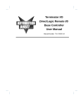
DL250 / DL350 / DL450
CPU With T1K–RSSS
Remote I/O System
In This Chapter. . . .
14
Ċ DL250/D350/DL450CPU Bottom Port as Remote Master
Ċ Remote Slave (T1K-RSSS) Features
Ċ Configuring the Bottom Port of the DL250/DL350/450 CPU
Ċ Setting the T1K-RSSS Rotary Switches
Ċ Setting the T1K-RSSS DIP Switches
Ċ Examples for Typical Configurations
Ċ DL250/DL350/DL450 Reserved Memory for Bottom Port
Ċ DL250/DL350/DL450 V Memory Port Setup Registers
Ċ Connecting the Wiring
Ċ Special CPU Memory for Diagnostics
4–2
DL250/DL350/DL450 CPU with T1K–RSSS Remote I/O System
DL250/DL350/DL450 CPU Bottom Port as Remote Master
For the D2–250, D3–350 CPU or D4–450, the most cost-effective way to add remote
I/O is to use the bottom port of the CPU as a remote master. The restriction is that it
operates in the RM–NET protocol only, which means a maximum of seven slaves at
a maximum baud rate of 38.4 kBaud. Also, the slave serial communications port is
not active in RM–NET protocol.
This configuration requires some setup programming for the CPU. You can write
your program using either a handheld programmer or DirectSOFT Programming
Software. The examples that follow will show you how to do this using DirectSOFT.
To get started, launch DirectSOFT and carry out the normal DirectSOFT setup
procedures for communicating with your DL250, DL350 or DL450 CPU. If you do not
know how to do this, refer to your DirectSOFT User Manual. Your PLC User
Manuals have very good coverage of the basic commands available and examples
of using the commands to write general ladder logic. We will be showing you in this
chapter only those commands that pertain to setting up your remote I/O initialization.
Built In Remote I/O Master Port
DL250/DL350/DL450 CPU
T1K–RSSS Remote I/O
DL450
DL350
DL250
RM–NET
Master
Port 2
RM–NET
Master
Remote I/O Master Functional Specifications
CPU built-in Remote I/O channels
Maximum I/O points supported by each channel
Maximum number of remote I/O slaves per channel
DL250
DL350
DL450
1
1
1
2048*
2048*
2048*
7
7
7
Transmission Distance (max.)
Communication Method
Port 3
3900 feet (1.2Km)
Asynchronous (half–duplex)
X Inputs available for Remote I/O
512
512
1024
Y Outputs available for Remote I/O
512
512
1024
Control Relays available for Remote I/O
1024
1024
2048
V Memory (words) available for Remote I/O
7168
7168
14848
*Requires CPU firmware version: D2–250 version 1.51 or later, D3–350 version 1.30
or later, and D4–450 version (SH)1.460 or (SH)2.460 or later. Earlier firmware
version supports 512 I/O points per channel.
4–3
DL250/DL350/DL450 CPU with T1K–RSSS Remote I/O System
Remote Slave (T1K-RSSS) Features
Top View
Bottom View
RUN--Turns ON when
communication is active.
DIAG--Turns ON when there
is a slave hardware failure.
I/OFast Blink: I/O error (250ms on/off
time)
Slow Blink: I/O configuration
error while outputs are enabled
(500ms on/off time)
Continuous ON: I/O Configuration
and I/O error simultaneously
Output Enable
Switch
-T
-1
-2
-3
Unit Address
Switches
Remote I/O
Connector
LINK--Turns ON when there is a
communications error.
Serial Port
T1K-RSSS
1 PULL TO UNLOCK
(Supported by
SM–NET only)
Remote I/O
Connector
Functional
Max. # of Slaves per channel
Specifications
Maximum # of I/O Modules per Slave
RM–NET
7
16 (be sure to check power budget)
Module Type
Non–intelligent slave
Digital I/O Consumed
Consumes remote I/O points at a rate equal to
the number of I/O points configured in each unit.
Communication Baud Rates
RM–NET
Selectable:
19.2K baud
38.4k baud
Communication Failure Response
Selectable to clear or hold last state of outputs
DL250/DL350/DL450 CPU
T1K–RSSS Remote I/O
Maximum Remote I/O Points per CPU DL250, DL350 and DL450 support a maximum of
2048 points per channel. The actual I/O available
is limited by total available references. For examNote: 8 channel analog modules
ple, the DL250 has a total of 512 X inputs and
consume 256 discrete I/O pts.
512 Y outputs. Mapping remote I/O into control
and 16 channel analog modules
relays or V memory of could allow more I/O
consume 512 I/O pts.
points for the DL250.
V memory addressing is recommended when using analog I/O
modules.
4–4
DL250/DL350/DL450 CPU with T1K–RSSS Remote I/O System
The following specifications define the operating characteristics of the
T1K–RSSS module.
DL250/DL350/DL450 CPU
T1K–RSSS Remote I/O
Physical
Installation Requirements
Specifications
mount to right of first power supply
Base Power Requirement
250 mA maximum
Communication Cabling
for remote I/O, RS-485 twisted pair, Belden
9841 or equivalent
Slave Serial Communications Port
not active in RM–NET mode
Operating Temperature
32 to 131° F (0 to 55_ C)
Storage Temperature
–4 to 158° F (–20 to 70_ C)
Relative Humidity
5 to 95% (non-condensing)
Environmental air
No corrosive gases, pollution level = 2
(UL 840)
Vibration
MIL STD 810C 514.2
Shock
MIL STD 810C 516.2
Noise Immunity
NEMA ICS3–304
Impulse noise 1us, 1000V
FCC class A
RFI (144MHz, 430MHz, 10W, 10cm)
4–5
DL250/DL350/DL450 CPU with T1K–RSSS Remote I/O System
Configuring the Bottom Port of the DL250/DL350/DL450 CPU
To configure the port using the Handheld Programmer, use AUX 56 and follow the
prompts, making the same choices as indicated below on this page. To configure the
port in DirectSOFT, choose the PLC menu, then Setup, then Setup Secondary
Comm Port. The port can also be configured using ladder logic code.
S
S
Port: From the port number list box at the top, choose “Port 2” for the
DL250 and DL350. Choose “Port 3” for the DL450.
Protocol: Click the check box to the left of “Remote I/O” (called
“M–NET” on the HPP), and then you’ll see the dialog box shown below.
Setup Communication Ports
Port:
Protocol:
Memory Address:
Station Number:
Baud Rate:
S
S
K-sequence
DirectNET
MODBUS
Non-sequence
Remote I/O
V37700
0
Close
Help
ChoosePort 3 for
DL–450
38400
Memory Address: Choose a V-memory address to use as the starting
location of a Remote I/O configuration table (V37700 is the default). This
table is separate and independent from the table for any Remote
Master(s) in the system.
Station Number: Choose “0” as the station number, which makes the
DL250, DL350 or DL–450 the master. Station numbers 1–7 are reserved
for remote slaves.
Baud Rate: The baud rates 19200 and 38400 baud are available.
Choose 38400 initially as the remote I/O baud rate, and revert to 19200
baud if you experience data errors or noise problems on the link.
Important: You must configure the baud rate on the Remote Slaves (via
DIP switches) to match the baud rate selection for the CPU’s Port 2
(DL450 port 3).
Then click the button indicated to send the Port 2
or Port 3 configuration to the CPU, and click Close.
DL250/DL350/DL450 CPU
T1K–RSSS Remote I/O
S
Port 2
4–6
DL250/DL350/DL450 CPU with T1K–RSSS Remote I/O System
Setting the T1K–RSSS Rotary Switches
The slave has two small rotary switches to set the unit address. They are on the face
of the module, with the label “UNIT ADRS” beside it. Adjust the switches by rotating
them with a small flathead screwdriver.
Remote Slave
Remote Master
(DL250, 350 or 450)
Address
Selection
Switches
DL250/DL350/DL450 CPU
T1K–RSSS Remote I/O
Set Port 2
(Port 3 DL450)
Address to 0
using
DirectSoft or
ladder logic
code
One switch is marked X1 and the other X10. Don’t confuse these with the
conventional data type labeling – these do not refer to inputs X1 and X10. Instead,
these set the address in decimal for each unit. X1 is the “one’s” position and X10 is
the “ten’s” position. For example, set address 7 by turning the X10 switch to 0 and the
X1 switch to 7.
Set them to any number 1–7 for RM–NET. Two slaves cannot have the same number
if they are linked to the same master. Always use consecutive numbers for
slaves, starting with Address 1—don’t skip numbers.
4–7
DL250/DL350/DL450 CPU with T1K–RSSS Remote I/O System
Setting the T1K–RSSS DIP Switches
The remote slave has an 8–position DIP switch labeled “SW1” that is located on the
side of the module under a hinged cover. Set these switches to configure the
protocol mode, the baud rate, the output response on communication failure. The
slave serial port is not active in RM–NET mode. The word “ON” appears beside the
switch to indicate the ON position.
Remote Slave
(T1K–RSSS)
DIP Switch located under
hinged cover
DIP
Switches
DIP Position
Module
1
Slave
2,3,4
5
Mode
Baud Rate
Output Default
OFF=SM–NET
Switch
Position
OFF=Clear
(T1K–RSSS)
ON=RM–NET Baud Rate
2 3 4
ON=Hold
19.2K
O O O
38.4K
X O O
Note: Higher baud rate are
not supported by RM–NET
6,7,8
Serial Port not active in
RM–NET mode
DL250/DL350/DL450 CPU
T1K–RSSS Remote I/O
DIP Switch Settings
4–8
DL250/DL350/DL450 CPU with T1K–RSSS Remote I/O System
Mode: DIP switch Position 1 on both the master and slave unit selects the protocol
mode for the remote I/O link. Since the CPU port only supports the RM–NET
protocol, Position 1 of the master and all slaves linked to it must be set to the ON
position in order to communicate.
Baud Rate: RM–NET protocol mode supports either 19.2K or 38.4K baud. In this
mode, only switch Position 2 is used to set the baud rate. Be sure to set switches 3
and 4 OFF. All stations on a remote I/O link must have the same baud rate before the
communications will operate properly.
Output Default: DIP switch Position 5 on the slave determines the outputs’
response to a communications failure. If DIP switch 5 is ON, the outputs in that slave
unit will hold their last state upon a communication error. If OFF, the outputs in that
slave unit will turn off in response to an error. The setting does not have to be the
same for all the slaves on an output channel.
The selection of the output default mode will depend on your application. You must
consider the consequences of turning off all the devices in one or all slaves at the
same time vs. letting the system run “steady state” while unresponsive to input
changes. For example, a conveyor system would typically suffer no harm if the
system were shut down all at once. In a way, it is the equivalent of an “E–STOP”. On
the other hand, for a continuous process such as waste water treatment, holding the
last state would allow the current state of the process to continue until the operator
can intervene manually .
DL250/DL350/DL450 CPU
T1K–RSSS Remote I/O
WARNING: Selecting “HOLD LAST STATE” as the default mode means that
outputs in the remote bases will not be under program control in the event of a
communications failure. Consider the consequences to process operation
carefully before selecting this mode.
4–9
DL250/DL350/DL450 CPU with T1K–RSSS Remote I/O System
Example Program Using Discrete I/O Modules
Example 1:
Using X and Y
Addresses as
the Remote I/O
Memory Types
A typical system uses X and Y memory types for the inputs and outputs on the
remote I/O channel.
To illustrate the setup program for this configuration, we will use the remote I/O
system below, shown with the completed Channel Configuration Worksheet.
The first block of logic tells the CPU the station number of the port, communication
V-memory address, and the baud rate setting. Define the constant value based on
these selections (see DL250/DL350/DL450 Reserved Memory Table at the end of
this chapter), and then write the value to the reserved V-memory address in the
CPU. You can also perform this function interactively with DirectSOFT (see
“Configuring the Bottom Port of the CPU“, earlier in this chapter).
Write Port Setup Word
DL350 CPU in Main Base (–1 base addressing)
DL250 CPU in Main Base
250
CPU
16
16
16
16
16
I
I
I
O
O
X0-X17 X20-X37 X40-X57 Y0-Y17 Y20-Y37
V40400 V40401 V40402 V40500 V40501
bottom
port of CPU
is remote
master
16
16
16
16
O
O
I
I
350
CPU
Y60–Y77 Y40–Y57 X20-X37 X0-X17
V40503 V40502 V40401 V40400
bottom port of
CPU is remote
master
to thoroughly understand addressing
conventions and restrictions for the
DL350, refer to the DL305 User
Manual
the setup program will be identical
for either a DL250 or DL350 CPU
Channel Configuration Worksheet
DL250/DL350/DL450 CPU Bottom Port
1st Remote
16
I
16
8
16
16
I
I
O
O
Circle one selection or fill in blank for each parameter
Configuration Parameter
SELECTION
Baud Rate (in KBaud), determined by required
distance to last slave
Remote I/O Configuration table Starting address
19.2
38.4
37700
V__________
(V37700 is default)
X200–X217 X220-X237 X240-X247 Y200-Y217 Y220-Y237
V40410 V40411 V40412
V40510
V40511
2nd Remote
PS
T1K–
RSSS
Slave
Station
8
8
16
I
I
O
X260–X267 X270–X277 Y240–Y257
V40413
V40512
The port setup ladder code is optional.
The port can be setup using DirectSoft
SP0
LD
OUT
Kbfc0
Constant defines station as master,
V-memory table at V37700, and
baud rate of 38.4 kBaud
V7656 V-memory address of setup word
OUT V777 for DL450
See Port Setup Registers later in this
chapter for more information
1
2
3
4
5
6
7
INPUT
Input Address
V40410
V40413
OUTPUT
No. of Inputs Output Address No. of Outputs
48
16
V40510
V40512
32
16
DL250/DL350/DL450 CPU
T1K–RSSS Remote I/O
PS
T1K–
RSSS
4–10
DL250/DL350/DL450 CPU with T1K–RSSS Remote I/O System
To calculate the input and output addresses and ranges, complete the Remote Slave
Worksheets and fill in the V-memory addresses for each slave, not just the first one.
You can transfer this data to the Channel Configuration Worksheet to condense it, or
fill in the Channel Worksheet directly if you choose not to use the Remote Slave
Worksheets.
Calculate input and output addresses
and ranges for each remote base
1st Remote
PS
T1K–
RSSS
16
16
I
8
I
16
I
Remote Slave Worksheet
1
Remote Base Address_________(Choose
1–7 for RM–NET or 1–31 for SM–NET)
16
O
O
X200–X217 X220-X237 X240-X247 Y200-Y217 Y220-Y237
V40410 V40411 V40412
V40510
V40511
2nd Remote
INPUT
OUTPUT
Slot
Number
Module
Name
0
16ND3
X200
1
16ND3
X220
16
2
08ND3
X240
16 (8 used)
3
4
Output Address
No. of Outputs
16TD1
Y200
16
16TD1
Y220
16
Input Address
No. of Inputs
16
5
PS
T1K–
RSSS
8
8
16
6
I
I
O
7
X260–X267 X270–X277 Y240–Y257
V40413
V40512
X200
Input Bit Start Address:________V-Memory
Address*:V_______
40410
48
Total Input Points_____
Y200
40510
Output Bit Start Address:________V-Memory
Address*:V______
32
Total Output Points_____
Channel Configuration Worksheet
DL250/DL350/DL450 CPU Bottom Port
Circle one selection or fill in blank for each parameter
Configuration Parameter
SELECTION
Baud Rate (in KBaud), determined by required
distance to last slave
Remote I/O Configuration table Starting address
DL250/DL350/DL450 CPU
T1K–RSSS Remote I/O
Slave
Station
1
2
3
4
5
6
7
INPUT
Input Address
V40410
V40413
19.2
38.4
Remote Slave Worksheet
37700
V__________
(V37700 is default)
OUTPUT
No. of Inputs Output Address No. of Outputs
48
16
* The D2–RMSM automatically assigns I/O addresses in sequence based on
Slave # 1’s starting addresses. The DL250/DL350/DL450 CPU port setup
program requires these addresses for each slave.
V40510
V40512
32
16
2
Remote Base Address_________(Choose 1–7 for RM–net or 1–31 for SM–NET)
INPUT
OUTPUT
Slot
Number
Module
Name
Input Address
0
08ND3
X260
8
1
08ND3
X270
8
2
16TD1
No. of Inputs
Output Address
No. of Outputs
Y240
16
3
4
5
6
7
X260
40413
Input Bit Start Address:________V-Memory
Address*:V_______
16
Total Input Points_____
Y240
40512
Output Bit Start Address:________V-Memory
Address*:V_______
16
Total Output Points_____
* The D2–RMSM automatically assigns I/O addresses in sequence based on
Slave # 1’s starting addresses. The DL250/DL350/DL450 CPU port setup
program requires these addresses for each slave.
NOTE: Configuring remote I/O for the DL250, DL350 DL450 CPU port requires both
the starting addresses and the number of input and output points for each slave. The
starting addresses for each slave must be on a 16-point boundary. In this example,
this means that X250–X257 in Slave # 1 are unused.
4–11
DL250/DL350/DL450 CPU with T1K–RSSS Remote I/O System
The second block of logic tells the CPU, for each slave, the starting V-memory
addresses for the inputs and outputs, and the total number of each. The CPU has
reserved memory locations, called pointers, that accomplish this task. Use the
values from the Remote Slave Worksheets or the Channel Configuration Sheet and
the pointer addresses from the DL250/DL350/DL450 Reserved Memory Table to
complete this logic.
Write Input and Output Pointers and
Ranges for each remote base
DL250/DL350/DL450 Reserved Memory Table
Port Setup Word
V7656
Setup Complete Flag
Channel Configuration Worksheet
DL250/DL350/DL450 CPU Bottom Port
Circle one selection or fill in blank for each parameter
Configuration Parameter
SELECTION
Baud Rate (in KBaud), determined by required
distance to last slave
Remote I/O Configuration table Starting address
Slave
Station
1
2
3
4
5
6
7
INPUT
Input Address
V40410
V40413
19.2
38.4
37700
V__________
(V37700 is default)
OUTPUT
No. of Inputs Output Address No. of Outputs
48
16
V40510
V40512
32
16
Slave
Input
Address
Number of
Input Pts
C740
Output
Address
Number of
Output Pts
1
V37704 V37705 V37706 V37707
2
V37710 V37711 V37712 V37713
3
V37714 V37715 V37716 V37717
4
V37720 V37721 V37722 V37723
5
V37724 V37725 V37726 V37727
6
V37730 V37731 V37732 V37733
7
V37734 V37735 V37736 V37737
SP0
LDA
O40410
Remote #1
Input
V37704 reserved V–memory
LD
K48
V37705
LDA
O40510
Output address
V37707
LDA
O40413
total outputs
reserved V–memory
Input address
OUT
V37710 reserved V–memory
LD
K16
OUT
V37711
LDA
O40512
total inputs
reserved V–memory
Output address
OUT
V37712 reserved V–memory
LD
K16
OUT
V37713
total outputs
reserved V–memory
DL250/DL350/DL450 CPU
T1K–RSSS Remote I/O
K32
Remote #2
Output
reserved V–memory
V37706 reserved V–memory
OUT
Remote #2
Input
total inputs
OUT
LD
SP0
Input address
OUT
OUT
Remote #1
Output
V777 for
DL450
4–12
DL250/DL350/DL450 CPU with T1K–RSSS Remote I/O System
Once you have written all of the logic to map the starting addresses and point totals
for each remote base, you have to zero out all of the reserved memory locations you
are not going to use and then tell the CPU that you are finished with the setup. If you
don’t insert zeros in the unused areas, the CPU will assume that every pointer
address V37714 through V37736 is pointing to a read or write start address. This
could cause problems; you may have garbage in these locations. At the very least, it
will take up unnecessary scan time.
The most efficient method for zeroing out the unused memory is to use LDD and
OUTD instructions (load and store double) to clear two consecutive memory
locations at a time. The following logic shows how to finish the setup program for this
example.
First scan relay contact
SP0
There are 20
unused reserved
memory locations.
LDD
K0
OUTD
V37714
OUTD
V37716
Load 32 bit accumulator with “0”
Where the unused memory starts
Clear all unused V-memory locations, 2
locations at a time
OUTD
V37720
OUTD
V37722
OUTD
V37724
OUTD
V37726
OUTD
V37730
SP0
OUTD
V37732
DL250/DL350/DL450 CPU
T1K–RSSS Remote I/O
OUTD
V37734
OUTD
V37736
C740
SET
Tell CPU that setup is completed
4–13
DL250/DL350/DL450 CPU with T1K–RSSS Remote I/O System
Completed Setup Program for DL250/DL350/DL450 as Remote Master
using X and Y Memory Addressing
RLL Program
SP0
K1
GTS
Main Program Body
SP0
Go to remote
I/O subroutine
K0
from bottom of previous column
END
Clear Unused
Memory
first scan relay
SP0
Set port data
LD
Kbfc0
OUT
V7656
LD
port setup word
K8
OUTD
V37720
Constant defines port as master,
V-memory table at V37700, and
baud rate of 38.4 kBaud
LD
K500
OUT
V7657
SP0
LDA
O40410
Remote #1
Input
V37724
OUTD
Data selects Remote I/O
OUTD
V37726
LD
K48
LDA
O40510
K32
Clear Unused
Memory
OUTD
V37734
OUTD
V37736
Input address
C740
SET
Tell CPU that setup is
completed
total inputs
reserved V–memory
RT
LD
Output address
LDA
O40413
total outputs
reserved V–memory
Input address
DL250/DL350/DL450 Reserved Memory Table
Port Setup Word
OUT
V37710 reserved V–memory
LD
K16
OUT
V37711
total inputs
reserved V–memory
V7656
Setup Complete Flag
Slave
Input
Address
Number of
Input Pts
C740
Output
Address
Number of
Output Pts
1
V37704 V37705 V37706 V37707
O40512 Output address
2
V37710 V37711 V37712 V37713
OUT
3
V37714 V37715 V37716 V37717
4
V37720 V37721 V37722 V37723
total outputs
5
V37724 V37725 V37726 V37727
reserved V–memory
6
V37730 V37731 V37732 V37733
7
V37734 V37735 V37736 V37737
LDA
V37712 reserved V–memory
LD
K16
OUT
V37713
V777 for
DL450
DL250/DL350/DL450 CPU
T1K–RSSS Remote I/O
V37707
to top of next column
V37732
K5000 for DL450 (register setting
provided)
V767 for DL450
V37706 reserved V–memory
OUT
Remote #2
Output
OUTD
OUT
LD
Remote #2
Input
V37730
SP0
V776 for DL450
V37704 reserved V–memory
V37705
SP0
V37722
OUTD
OUT
OUT
Remote #1
Output
OUTD
V777 for DL450
OUT
V7655
OUTD
V37716
Remote I/O Subroutine
SBR K1
Load 32-bit accumulator
with “0”
OUTD
Clear all unused VV37714 memory locations
LDD
4–14
DL250/DL350/DL450 CPU with T1K–RSSS Remote I/O System
Example Program Using Analog I/O Modules
Example 2:
Using V Memory
Addresses as the
Remote I/O
Memory Type
The following example uses Terminator discrete and analog I/O modules. It is
recommended to use V memory addressing when using analog modules
since each analog I/O channel uses a double (two) word each. Thus, an 8
channel analog I/O module uses 256 discrete points and a 16 channel analog I/O
module uses 512 discrete points. Analog output modules are configured using
the Module Control Byte located in the most significant byte of the most significant
word of channel 1 of the module. V memory addressing requires the use of
“Bit–of–Word” instructions to address the I/O points.
DL250 CPU in Main Base
Remote Slave Worksheet
250
CPU
bottom
port of CPU
is remote
master
PS
16
16
16
16
16
I
I
I
O
O
1
Remote Slave Address_________(Choose
1–7 for RM–NET or 1–31 for SM–NET)
T1K–
RSSS
16
16
Input Address
No. Inputs
0
16ND3
V3000
16
1
16ND3
V3001
16
2
08AD2
V3002
256
16
3
08DA2
V3100
256
O
4
16TD1
V3120
16
I
I
V3000
V3001
T1F–08AD–2
256
I
256
O
OUTPUT
Module
Name
X0-X17 X20-X37 X40-X57 Y0-Y17 Y20-Y37
V40400 V40401 V40402 V40500 V40501
1st Remote
INPUT
Module
Number
Output Address
No.Outputs
5
V3002–
V3021
V3100– V3120
V3117
6
7
T1F–08DA–2
2nd Remote
PS
T1K–
RSSS
8
8
16
I
I
O
DL250/DL350/DL450 CPU
T1K–RSSS Remote I/O
V3030
V3000.0
Input Bit Start Address:________V-Memory
Address*:V_______
V3000
288
Total Input Points_____
V3100.0
V3100
Output Bit Start Address:________V-Memory
Address*:V______
272
Total Output Points_____
V3130
Channel Configuration Worksheet
* The D2–RMSM automatically assigns I/O addresses in sequence based on
Slave # 1’s starting addresses. The DL250/DL350/DL450 CPU port setup
program requires these addresses for each slave.
DL250/DL350/DL450 CPU Bottom Port
Remote Slave Worksheet
2
Remote Base Address_________(Choose 1–7 for RM–net or 1–31 for SM–NET)
Circle one selection or fill in blank for each parameter
Configuration Parameter
SELECTION
Baud Rate (in KBaud), determined by required
distance to last slave
Remote I/O Configuration table Starting address
Slave
Station
1
2
3
4
5
6
7
19.2
38.4
V3000
V3030
OUTPUT
No. of Inputs Output Address No. of Outputs
288
16
V3100
V3130
272
16
OUTPUT
Module
Name
0
08ND3
V3030
8
1
08ND3
V3030.10
8
2
16TD1
37700
V__________
(V37700 is default)
INPUT
Input Address
INPUT
Slot
Number
Input Address
No. Inputs
Output Address
V3130
No.Outputs
16
3
4
5
6
7
V3030.0
V3030
Input Bit Start Address:________V-Memory
Address*:V_______
16
Total Input Points_____
V3130.0
V3130
Output Bit Start Address:________V-Memory
Address*:V_______
16
Total Output Points_____
* The D2–RMSM automatically assigns I/O addresses in sequence based on
Slave # 1’s starting addresses. The DL250/DL350/DL450 CPU port setup
program requires these addresses for each slave.
4–15
DL250/DL350/DL450 CPU with T1K–RSSS Remote I/O System
This block of logic tells the CPU, for each slave, the starting V-memory addresses for
the inputs and outputs, and the total number of each. Use the values from the
Remote Slave Worksheets or Channel Configuration Worksheet and the pointer
addresses from the DL250/DL350/DL450 Reserved Memory Table to complete the
logic.
Write Input and Output Pointers and
Ranges for each remote base
DL250/DL350DL450 Reserved Memory Table
Port Setup Word
V7656
Setup Complete Flag
Slave
Channel Configuration Worksheet
DL250/DL350/DL450 CPU Bottom Port
Circle one selection or fill in blank for each parameter
Configuration Parameter
SELECTION
Baud Rate (in KBaud), determined by required
distance to last slave
Remote I/O Configuration table Starting address
Slave
Station
1
2
3
4
5
6
7
19.2
38.4
37700
V__________
(V37700 is default)
INPUT
Input Address
V3000
V3030
Input
Address
Number of
Input Pts
V777 for
DL450
C740
Output
Address
Number of
Output Pts
1
V37704 V37705 V37706 V37707
2
V37710 V37711 V37712 V37713
3
V37714 V37715 V37716 V37717
4
V37720 V37721 V37722 V37723
5
V37724 V37725 V37726 V37727
6
V37730 V37731 V37732 V37733
7
V37734 V37735 V37736 V37737
OUTPUT
No. of Inputs Output Address No. of Outputs
288
16
V3100
V3130
272
16
SP0
LDA
O3000
Remote #1
Input
OUT
V37704 reserved V–memory
LD
K288
OUT
V37705
LDA
O3100
K272
V37707
LDA
O3030
total outputs
reserved V–memory
Input address
OUT
V37710 reserved V–memory
LD
K16
OUT
V37711
LDA
Remote #2
Output
Output address
V37706 reserved V–memory
OUT
Remote #2
Input
reserved V–memory
OUT
LD
SP0
total inputs
O3130
total inputs
reserved V–memory
Output address
OUT
V37712 reserved V–memory
LD
K16
OUT
V37713
total outputs
reserved V–memory
Since the rest of the logic is identical to Example 1, we will now show the completed
setup program.
DL250/DL350/DL450 CPU
T1K–RSSS Remote I/O
Remote #1
Output
Input address
4–16
DL250/DL350/DL450 CPU with T1K–RSSS Remote I/O System
Completed Setup Program for DL250/DL350/DL450 as Remote Master
using V Memory Addressing
RLL Program
SP0
K1
GTS
SP0
Go to remote
I/O subroutine
Main Program Body
K0
from bottom of previous column
END
Clear Unused
Memory
first scan relay
SP0
LD
OUT
V7656
LD
K8
port setup word
OUT
V7655
LD
K500
OUT
V7657
SP0
LDA
O3000
Remote #1
Input
OUTD
V37720
Constant defines port as master,
V-memory table at V37700, and
baud rate of 38.4 kBaud
OUTD
V37722
OUTD
Kbfc0
Set port data
V37724
V777 for DL450
OUTD
Data selects remote I/O
OUTD
V37726
V37730
V776 for DL450
SP0
K5000 for DL450 (register setting
Provided)
V767 for DL450
Clear Unused
Memory
OUTD
V37732
V37734
OUTD
C740
SET
V37704 reserved V–memory
K288
OUTD
V37736
Input address
OUT
LD
OUTD
V37716
Remote I/O Subroutine
SBR K1
Load 32-bit accumulator
with “0”
OUTD
Clear all unused VV37714 memory locations
LDD
total inputs
Tell CPU that setup is
completed
RT
OUT
reserved V–memory
V37705
LDA
O3100
DL250/DL350/DL450 CPU
T1K–RSSS Remote I/O
Remote #1
Output
Output address
Analog Programming example
continued on next page
OUT
V37706 reserved V–memory
LD
K272
OUT
V37707
SP0
LDA
O3030
total outputs
reserved V–memory
Input address
DL250/DL350/DL450 Reserved Memory Table
OUT
Remote #2
Input
LD
K16
OUT
V37711
LDA
O3130
Remote #2
Output
Output address
OUT
V37712 reserved V–memory
LD
K16
OUT
total outputs
V37713 reserved V–memory
to top of next column
Setup Complete Flag
total inputs
reserved V–memory
V7656
Port Setup Word
V37710 reserved V–memory
Slave
Input
Address
Number of
Input Pts
C740
Output
Address
Number of
Output Pts
1
V37704 V37705 V37706 V37707
2
V37710 V37711 V37712 V37713
3
V37714 V37715 V37716 V37717
4
V37720 V37721 V37722 V37723
5
V37724 V37725 V37726 V37727
6
V37730 V37731 V37732 V37733
7
V37734 V37735 V37736 V37737
V777 for
DL450
4–17
DL250/DL350/DL450 CPU with T1K–RSSS Remote I/O System
Completed Setup Program for V–Memory Addressing (con’t)
Main Program Body
V3002
– Bipolar
– 0–5VDC
SP1
SP0
Set Analog
Output Module
Control Bits
SP1
LD
BCD
OUT
V3500
B3101.10
OUT
0= All module outputs OFF
1= All module outputs Enabled
B3101.11
SET
0= Unipolar
1=Bipolar
B3101.12
RST
V3002
>
_
K2000
LD
ADDB
OUT
V3100
K1FFF
OUT
V4000
Analog output data register
OUT
V3116
The OUT instruction sends the data to
channel 1 of the analog output module
C0
OUT
B3030.0
Loads analog input channel 1 data into
The INVERT and ADDB instructions
convert the incoming 2’s compliment
signal data to binary plus sign bit.
K1
ANDD
The BIN instruction converts the accumulator
data to binary (omit this step if the conversion
is done elsewhere.)
BIN
The OUT instructions stores the BCD
data in a new register
INV
Read Negative
Analog Input
Data
0= 5V Range
1=10V Range
Use the BCD instruction to convert thebinary analog input data to BCD if
necessary to do math or other BCD
operations
V3000 the accumulator
K2000 is used above
to monitor the channel
sign bit. It comes ON if
the signal is negative.
V2100
Loads analog input channel 1 data into
V3000 the accumulator
Analog Output Module Control Bits
LD
Send Data to
Analog Output
Module
K2000
Read Positive
Analog Input
Data
Configure T1K–08DA–2 Analog Output Module:
Use X, C, etc. permissive
contact if needed
<
Mask channel sign bit
The OUT instructions stores the binary
data in a new register. Add a BCD instruction prior to this OUT instruction if i
is necessary to convert to BCD
Channel 1 data is negative when C0 is
ON
B3130.12
Example of discrete remote
OUT
I/O point addressing
The OUT instruction sends the data to
channel 8 of the analog output module
The Control Bits of an Analog Output module are located in the most significant byte
of the most significant word of the first output channel (channel 1).
Channel 1 Memory Map
of 8&16-Channel Analog Output Module
(T1F–08DA, T1F–016DA)
07
06
05
04
03
02
01
00
Octal Bit
07
06
05
04
03
02
01
00
Size
Analog Value Channel 1
Write Byte 1
Analog Value Channel 1
Write Byte 2
not used
Write Byte 3
Module Control Byte
Write Byte 4
Module Control Byte of 8&16-Channel Analog Output Module
(T1F–08DA, T1F–16DA)
Decimal Bit
31
30
29
28
27
26
25
24
Octal Bit
37
36
35
34
33
32
31
30
Read/Write
Bit 24
Outputs Enable
0 = All outputs OFF
1 = All outputs Enabled
Write
Bit 25
Unipolar / Bipolar
0 = Unipolar selected
1 = Bipolar selected
Write
Bit 26
5V / 10V Range
0 = 5V range
1 = 10V range
Write
Bit 27
0 – 20mA / 4–20mA Range
0 = 0 – 20mA range
1 = 4 – 20mA range
Write
Bit 28 – 31
Reserved for system use
–
DL250/DL350/DL450 CPU
T1K–RSSS Remote I/O
Decimal Bit
4–18
DL250/DL350/DL450 CPU with T1K–RSSS Remote I/O System
DL250/DL350/DL450 Reserved Memory for Bottom Port
as Remote Master
This table provides a listing of the reserved memory addresses in the DL250/ DL350/DL450 CPU to
program the pointer addresses and ranges for slaves attached to the bottom port of the CPU.
DL250/DL350/DL450 Reserved Memory Table
Port Setup Word
Setup Complete Flag
Number of
Slave
Input
Reserved
1
2
3
4
5
6
7
V7656
V777(DL450)
C740
Output
Number of
Address
Input Points
Address
Output Points
V37700
V37704
V37710
V37714
V37720
V37724
V37730
V37734
V37701
V37705
V37711
V37715
V37721
V37725
V37731
V37735
V37702
V37706
V37712
V37716
V37722
V37726
V37732
V37736
V37703
V37707
V37713
V37717
V37723
V37727
V37733
V37737
DL250/DL350/DL450 CPU
T1K–RSSS Remote I/O
This table provides a listing of the control relay flags available for the setup and monitoring of remote I/O
attached to the bottom port of the DL250, DL350 and DL450 CPU.
Control Relays Used For Remote I/O
FLAG
ADDRESS
FUNCTION
C740
Setup Complete Flag
C741
Communications Error Response Flag
DETAIL
Set ON to command CPU to read and
check parameters loaded into setup
memory
This flag determines the CPU’s
response if there is a communications
error. Set ON to hold last state of
received inputs; set OFF to clear the
status of the received inputs.
4–19
DL250/DL350/DL450 CPU with T1K–RSSS Remote I/O System
DL250/DL350/DL450 V Memory Port Setup Registers
When configuring the bottom port of the DL250, DL350 or DL450 CPU via DirectSoft or the Handheld
Programmer, you are actually loading a reserved V-memory adddresses with configuration data. The
following diagrams define the meaning of the bits in the registers. The previous ladder logic examples
include logic in the setup program to set these parameters so they are not lost or accidentally changed.
Remote I/O Communication Port Settings:
DL250/DL350 (V7656); DL450 (V777)
15
8
7
0
LD Kbfc0 = V37700 as starting address pointer,
OR
38.4k baud and address 0
LD K3fc0 = V37700 as starting address pointer,
19.2k baud and address 0
OUT V7656 (V777 for DL450)
******* * ******* *
Station number setting
0 = Master station number
Communication V–memory address
(hex equivalent of octal adddress)
default 37700 is starting address of pointer table
Communication baud rate setting
0 = 19.2 kBaud
1 = 38.4 kBaud
Port 2 Protocol Setup: DL250/DL350 (V7655)
Port 3 Protocol Setup: DL450 (V776)
15
8
0 0 0 0
0
*0
0 0
LD K8 = Remote I/O
OUT V7655 (V776 for DL450)
1 = Selects Remote
not used for Remote I/O
Register Set Code: DL250/DL350 (V7657); DL450 (V767)
DL250/DL350:
15
8
** **** **
7
0
0 0 0 0 0 0 0 0
LD K500 = Port settings provided by user program
OUT V7656
DL450:
LD K5000 = Port settings provided by user program
OUT V767
DL250/DL350 Port 2 register set code
0101(5) = register setting provided by user program
DL450 Port 2 register set code
0101(5) = register setting provided by user program
DL250/DL350/DL450 CPU
T1K–RSSS Remote I/O
0 0 0 0 0 0 0 0
7
4–20
DL250/DL350/DL450 CPU with T1K–RSSS Remote I/O System
Connecting the Wiring
Cabling Between
the D2–250 CPU
Bottom Port and
Slaves
The standard remote I/O link is a 3-wire, half-duplex type. Since Port 2 of the DL250
CPU is a 5-wire full duplex-capable port, we must jumper its transmit and receive
lines together as shown below (converts it to 3-wire, half-duplex). The
recommended cabling for connecting the master and slaves is the single twisted pair
cable, Belden 9841 or equivalent. The diagram also depicts the port pinout for the
D2–250 CPU bottom port.
Port 2 Pin Descriptions (DL250 CPU)
1
2
3
4
5
6
7
8
9
10
11
12
13
14
15
6
11
1
10
15
5
15-pin Female
D Connector
RXD– DL250 CPU Port 2
Remote I/O Master
0V
7
DL250/DL350/DL450 CPU
T1K–RSSS Remote I/O
RXD+
5 VDC
Transmit Data (RS232C)
Receive Data (RS232C)
Ready to Send (RS–232C)
Clear to Send (RS–232C)
Receive Data – (RS–422)
Logic Ground
Logic Ground
Transmit Data + (RS–422)
Transmit Data – (RS–422)
Request to Send + (RS–422)
Request to Send – (RS–422)
Receive Data + (RS–422)
Clear to Send + (RS422)
Clear to Send – (RS–422)
Remote I/O Slave
(end of chain)
Remote I/O Slave
T
Termination
Resistor
5V
TXD
RXD
RTS
CTS
RXD2–
0V
0V
TXD2+
TXD2 –
RTS2 +
RTS2 –
RXD2 +
CTS2 +
CTS2 –
Jumper
T
TXD+ / RXD+
1
1
TXD– / RXD–
2
2
TXD+
TXD–
Signal GND
3
3
Internal
150 ohm
resistor
Connect shield
to signal ground
The twisted/shielded pair connects to the DL250’s Port 2 as shown. Be sure to
connect the cable shield wire to the signal ground connection. A termination resistor
must be added externally to the CPU, as close as possible to the connector pins. Its
purpose is to minimize electrical reflections that occur over long cables. Be sure to
add the jumper at the last slave to connect the required internal termination resistor.
Ideally, the two termination resistors at
T
Add series
the cable’s opposite ends and the
external
cable’s rated impedance will all three
resistor
1
Internal
match. For cable impedances greater
150 ohm
than 150 ohms, add a series resistor at the
resistor
2
last slave as shown to the right. If less than
150 ohms, parallel a matching resistance
across the slave’s pins 1 and 2 instead.
3
4–21
DL250/DL350/DL450 CPU with T1K–RSSS Remote I/O System
Cabling Between
the D3–350/D4–450
CPU Bottom Port
and Slaves
The remote I/O link is a 3-wire, half-duplex type. Since Port 2 of the DL350 and Port 3
of the DL450 CPU is a 5-wire full duplex-capable port, we must jumper its transmit
and receive lines together as shown below (converts it to 3-wire, half-duplex). The
recommended cabling for connecting the master and slaves is the single twisted pair
cable, Belden 9841 or equivalent. The diagram depicts the port pinout for the
D3–350 and D4–450 CPU bottom port.
The location of Port 2 on the DL350 is on
the 25-pin connector , as pictured to the
right. The location of Port 3 on the DL450
is on the 25–pin connector, which is also
shared by Port 1.
0V
Signal GND
S Pin 7
S Pin 12
TXD+
25 Pin Connector
S Pin 13
TXD–
DL350 Port 2 TXD+
DL450 Port 3 TXD–
S Pin 24
RXD+
S Pin 25
RXD–
0V
DL350 CPU Port 2
DL450 CPU Port 3
Remote I/O Master
7
Remote I/O Slave
1
13
14
25
RXD+
RXD–
Remote I/O Slave
(end of chain)
T
Termination
Resistor
Jumper
T
TXD+ / RXD+
1
1
TXD– / RXD–
2
2
Signal GND
3
RXD+
TXD+
TXD–
13
25
RXD–
3
Internal
150 ohm
resistor
The twisted/shielded pair connects to the DL350/DL450’s Port as shown. Be sure to
connect the cable shield wire to the signal ground connection. A termination resistor
must be added externally to the CPU, as close as possible to the connector pins. Its
purpose is to minimize electrical reflections that occur over long cables. Be sure to
add the jumper at the last slave to connect the required internal termination resistor.
Ideally, the two termination resistors at
the cable’s opposite ends and the
cable’s rated impedance will all three
match. For cable impedances greater
than 150 ohms, add a series resistor at the
last slave as shown to the right. If less than
150 ohms, parallel a matching resistance
across the slave’s pins 1 and 2 instead.
Remember to size the termination resistor
at Port 2 (Port 3 DL450) to match the
cable’s rated impedance. The resistance
values should be between 100 and 500
ohms.
Add series
external
resistor
T
1
2
3
Internal
150 ohm
resistor
DL250/DL350/DL450 CPU
T1K–RSSS Remote I/O
Connect shield
to signal ground
4–22
DL250/DL350/DL450 CPU with T1K–RSSS Remote I/O System
Special CPU Memory for Diagnostics
This table provides a listing of the control relay flags available in the DL250/DL350/DL450 for remote I/O
troubleshooting.
Remote I/O System Control Relays
FLAG
ADDRESS
FUNCTION
Setup Error– The corresponding relay will be ON if the setup table contains
an error (C750 =master, C751 = slave 1.....C757 = slave 7)
C760 to C767 Communications Ready – – The corresponding relay will be ON if the setup table
is valid (C760 =master, C751 = slave 1.....C767 = slave 7)
DL250/DL350/DL450 CPU
T1K–RSSS Remote I/O
C750 to C757