1
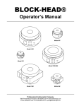
BLOCK-HEAD®
Operator’s Manual
www.airbearings.com
Model 4R
Model 10R
Model 3R
Model 10R-606
Model 10B
Model 4B
Professional Instruments Company
7800 Powell Road • Hopkins, MN 55343 USA
Phone (952)933-1222 • Fax (952)933-3315 • [email protected]
BLOCK-HEAD® Operator’s Manual
This air bearing is one of the world’s most precise mechanisms. It provides a convenient way to rotate a
component without friction or error motion, and with complete stability, high stiffness, and long service life. It is
easy to use, but successful installation depends on careful attention to details in this manual; it is also quite easy
to abuse. The keys to success:
1. Clean, flat surfaces
2. Clean, dry air
3. Know your loads and forces
If in doubt about any procedure in this manual, or just for a word of encouragement, call us! We are generally
available 7:00am - 5:00pm weekdays and many Saturday mornings.
Warranty
Material and workmanship are warranted for one year after seasonable acceptance by Buyer. Latent defects are
warranted on a prorated basis for the expected life stated by Buyer in Buyer’s Purchase Order.
Professional Instruments Company
i
BLOCK-HEAD® Operator’s Manual
STOP!
Before you unpack this bearing, feel it through the yellow plastic bag. If it feels cold, do not proceed with
unpacking until it has warmed to room temperature. This may take 24 hours. Condensation forming on a cold,
unpressurized bearing will damage it.
Professional Instruments Company
ii
BLOCK-HEAD® Operator’s Manual
Table of Contents
Air Supply .............................................................................................................. 1
Air Bearing Start-Up Procedure............................................................................. 2
Air Bearing Shut-Down Procedure ........................................................................ 3
Storing an Air Bearing Spindle .............................................................................. 4
Fixture and Adapter Plate Mounting ...................................................................... 5
Model GF-5 Precision-Ground Flatstones ............................................................. 6
Air Bearing Care and Maintenance ....................................................................... 7
Wet Environment Operation .................................................................................. 8
Low Distortion Mounting ........................................................................................ 9
High-Accuracy Fixturing ...................................................................................... 10
Spindle Drives...................................................................................................... 11
Mounting Guidelines for Models 4B and 10B ...................................................... 12
Mounting Guidelines for Model 4R ...................................................................... 13
Optional Pneumo-Lock ........................................................................................ 14
Pressure Switch................................................................................................... 15
Attachments......................................................................................................... 16
Load Capacity...................................................................................................... 17
BLOCK-HEAD® Air Bearing Spindle Specifications ........................................... 18
Technical Support................................................................................................ 19
Professional Instruments Company
iii
BLOCK-HEAD® Operator’s Manual
Air Supply
Air bearing spindles and slides require clean, dry, oil-free air at adequate pressure.
•
The relative humidity of the air at the bearing must be maintained at 85% or lower.
•
The air must be free of oil, tars, resins, and of particles larger than five micrometers.
•
The operating air pressure should be capable of supporting double the greatest anticipated load. Note
that the bearing’s load capacity varies directly with air pressure.
•
The pressure may be reduced when the bearing is not being used. By maintaining a flow of air through
the bearing, the interior surfaces are protected against contamination. We recommend an uninterrupted
supply of clean, dry air as the safest way to keep a bearing on standby, or in storage.
•
The pressure may be turned off only after careful cleaning and drying of the bearing’s exterior and
installation of the rotor lock.
Professional Instruments Company
1
BLOCK-HEAD® Operator’s Manual
Air Bearing Start-Up Procedure
1. Purge the air line with a brisk flow of air for at least one minute. Confirm that air-line humidity is below
85%.
2. Install the inlet line(s) as shown in the diagram below.
3. Partially open the regulator to purge the gauge ports.
4. Connect the gauge(s) and adjust the regulator for maximum pressure. The bearing gauge should read
within 5 psi of the regulator gauge. A larger pressure drop may indicate an air-line leak, obstruction, or
constriction. A model 4B will also show a pressure drop when its gauge ports are incorrectly used as
inlets; other BLOCK-HEAD® models have universal ports which may be used for inlet or gauge. Note that
any unused port must be plugged.
5. Remove the rotor lock. The rotor should now turn freely with just a finger touch. If it shows any sign of
stickiness, let it stand for 24 hours at maximum pressure before attempting further diagnosis; the
stickiness may be due to a minute amount of oil which found its way into the bearing by capillary action,
and must be cleared. Never force the rotor to turn if it is sticky. Test for stickiness by adding a slight
imbalance to the rotor (for instance, a single 10-32 screw). The rotor should oscillate several times before
stopping.
6. Reattach the rotor lock whenever the bearing is idling at low pressure or being stored or shipped without
pressure. The bearing will be damaged if it is rotated with insufficient pressure to support the load.
Professional Instruments Company
2
BLOCK-HEAD® Operator’s Manual
Air Bearing Shut-Down Procedure
Avoid bearing shut-down if possible. An unpressurized bearing is very vulnerable to damage by contamination. An
air bearing perpetually pressurized has the best chance of being trouble-free; if it is not overloaded, its service life
is virtually unlimited.
1. Install the rotor lock.
2. Dry the bearing. Use an absorbent swab in the corner where rotor and stator meet. Do not push debris
into the corner; instead, wipe away from the gap. Especially, do not use an air blast to dry the bearing.
3. Clean the bearing with a non-residual solvent such as acetone or isopropanol. Clean all accessible
surfaces, including the rotor’s bore and any unfilled tapped holes. Final cleaning with gage block cleaner
can help prevent surface rust, since the cleaner leaves a scant film of protective oil. Do not overdo it.
4. Let the bearing stand for 24 hours at a reduced (50 psi) pressure.
5. Turn off the air supply and remove the air line(s).
6. Place the bearing into the special plastic bag (as shipped) with a fresh pack of desiccant.
7. (Optional) Place the bagged spindle into the shipping drum, arranging the foam packing material as
shipped. Close the drum and seal it.
Professional Instruments Company
3
BLOCK-HEAD® Operator’s Manual
Storing an Air Bearing Spindle
The spindle can be safely stored without air if it is first cleaned and dried. Do not use a strong blast from a blow
gun in an attempt to dry the bearing; this air blast can drive liquid upstream into the thrust bearings, even with
150 psi on the spindle.
The best insurance against liquid penetration is to keep at least 10 psi pressure on the bearing at all times.
Provisions should be made to keep the spindle pressurized with clean, dry gas (i.e. dry nitrogen) anytime the
main air system is being serviced.
If the outer surfaces are to be protected by a rust-preventative oil, take care that it does not accumulate near the
rotor’s exhaust regions. Put a drop of oil on a clean cloth and wipe off the spindle. Do not force the cloth down into
the corner where the outer diameters of the rotor meet the shoulder of the stator. It is better to leave the corners
dry than to over-oil the bearing.
If the corner is dirty, clean it with a cotton swab soaked with solvent. Do not use a hard instrument like a
screwdriver.
Professional Instruments Company
4
BLOCK-HEAD® Operator’s Manual
Fixture and Adapter Plate Mounting
Do not disturb the 12 cap screws that hold the rotor’s thrust plates to the shaft.
Do not attempt to drill additional holes in any part of the spindle.
The rotor mounting surfaces are ground flat and perpendicular to the rotational axis of the spindle to 0.000,020.
Any stiff plate that is to be attached to the rotor should have comparable flatness. The degree of flatness required
increases with the stiffness of the plate. The mating surfaces should come into total area contact with only a few
pounds force. Heavy structures should be ground, lapped, or scraped flat enough to wring to the faceplate. As a
rule of thumb, generate 0.0001 per inch flatness of steel plate 0.25 thick, and 0.000,010 per inch for a steel plate
one inch thick. If in doubt, check for full contact by lightly bluing one member.
Screws should have at least 0.2 engagement, but they must not bottom in the hole. Before installing the plate,
measure the length under the head with the screw finger tight. It should be 0.2 less than the thickness of the
plate.
Clean the mating surfaces and check for nicks and burrs with a GF-5 Precision-Ground Flatstone or a gage block
stone. Reclean with a small amount of rust-preventative oil on a lint-free cloth. We use Rust-Lick 606, which is
available from:
Rust-Lick Company
30 Endicott Street
Danvers, MA 01923
Tighten 10-32 screws uniformly to 80 pound-inches or 1/4-20 screws to 120 pound-inches after applying a small
amount of grease on the end and under the head.
If the spindle is to be used for machining, the unused mounting holes can be plugged with screws to keep out
debris.
Professional Instruments Company
5
BLOCK-HEAD® Operator’s Manual
GF-5 Precision-Ground Flatstones
These stones have been ground flat on both faces with a diamond wheel. The long
sides are ground perpendicular to allow stoning up to a shoulder. The ends are
unground. The stones are used to remove the swellings which surround the
inevitable tiny nicks and dents found on any machined surface. They are much like
gage block stones, but with a more aggressive cutting action.
The stone’s porous structure allows asperities to penetrate far enough to be
trimmed off. When the raised area is reduced in height to about ten microinches,
the force is spread out between two relatively large flat surfaces, and cutting
activity substantially stops. Proper application will avoid scratching the work and
will prolong the useful life of the stone:
•
Prepare the work by locally removing large burrs with a file or an unground
stone. Clean with solvent and tissue.
•
Before stoning a workpiece, rub the two stones together to remove or
cut down embedded debris, which could scratch the work.
•
Slide the stones onto the workpiece with light pressure to avoid
scratches from loose particles. Small projections are easily felt if the
work is clean. Concentrate on the feel; loose debris can be felt rolling
around. Stop immediately and reclean.
•
Gradually bear down, always working in the direction of the original
grind lines on the work.
•
Clean the stones by spray rinsing or ultrasonic cleaning followed by air
blast. Store in the original container to avoid misuse on rough work.
Professional Instruments Company
6
BLOCK-HEAD® Operator’s Manual
Air Bearing Care and Maintenance
•
Observe the humidity level and take action if humidity exceeds 85%.
•
Use a rotor lock when not at maximum pressure. Inadvertent rotation without air pressure will generate
wear debris, which will bind up the spindle. This is particularly important during installation when several
people may be working near the spindle. Never rotate the spindle, even a little, without at least 50 psi
pressure.
•
Know your loads and forces. Be sure the supply pressure is adequate for the load. Never exceed 50% of
the ultimate load capacity.
•
Be sure the mating surfaces are flat, clean, and free of nicks and burrs. Full accuracy and load capacity
can be achieved only when the bearing surfaces are undistorted.
•
Use proper length screws; be sure the screw does not bottom in the hole because it is too long. Be sure
the threads are clean and undamaged. Observe the torque recommendations.
•
Observe safety precautions. Use adequate guards for high-rotational-energy applications.
•
The pressure may be turned off only after careful cleaning and drying of the bearing’s exterior and
installation of the rotor lock.
Professional Instruments Company
7
BLOCK-HEAD® Operator’s Manual
Wet Environment Operation
As long as a BLOCK-HEAD® spindle is pressurized, the exhaust air serves as a seal against contaminants; a
pressurized spindle will operate well in a dirty environment, under a flood of liquid, or even submerged. However,
a stream should not be directed at the exhaust region where the rotor and stator meet, since contaminants could
be forced upstream into the bearing. For this same reason, the bearing should not be cleaned with a blast of
compressed air.
When the spindle is depressurized, any moisture present at the exhaust regions will be drawn in by capillary
action, leading to sticky operation, error motion, loss of load capacity, or bearing failure. Before a spindle is
depressurized, it must be scrupulously dried, paying particular attention to the areas where the rotor and stator
meet. If liquids are likely to come in contact with a BLOCK-HEAD® spindle, we recommend fixture designs which
incorporate non-contact seal features, such as labyrinth seals or capillary seals.
Professional Instruments offers a standard selection of such seals, which will reduce the chance of bearing failure
from liquid intrusion. We have experience with very demanding sealing requirements, and will assist you in
choosing the best design for your application.
Labyrinth Seal
Professional Instruments Company
Capillary Seal
8
BLOCK-HEAD® Operator’s Manual
Low Distortion Mounting
Our published accuracy specifications apply to the undistorted spindle, carrying less than its maximum load. In
order to achieve the full potential accuracy of the spindle, meticulous attention to detail is required in mounting the
spindle’s stator to the machine and fixtures to the spindle’s rotor. The spindle is provided with mounting surfaces
that are flat to 20 microinches (0.5 micrometer); mating surfaces must be similarly flat in order to maintain
accuracy and load capacity. If a mating surface is not flat enough, the spindle will be distorted, possibly enough
that the spindle will have zero load capacity or even be locked.
Reduced screw tension will not compensate for out-of-flat mating surfaces, which will be pulled into contact with
an almost infinitesimally small force. The relationship between screw tension and the torque used to tighten the
screw is not at all precise since only 10 percent of the force actually stretches the screw; the other 90 percent
overcomes friction in the threads and under the screw head. It is possible to have zero tension on the bolted joint
despite high torque if the threads are rough or dirty, or if the screw bottoms-out in the hole. To prevent this, every
threaded joint should be checked by running the screw into the hole, making certain that it runs in freely 0.2
(5mm) beyond the depth needed to clamp the fixture.
Good lubrication will provide more uniformity of screw tension. Molybdenum disulfide powder or grease is very
effective. It should be applied under the screw’s head and on its first few threads.
When two flat surfaces are to be bolted together, the forces must be spread out to prevent localized distortion; in
other words, multiple fasteners are best. For example, a flat plate attached to the rotor of the four-inch
BLOCK-HEAD® spindle with only two screws at 0° and 180° will bend the rotor 100 microinches out-of-flat;
adding two more screws at 90° and 270° will reduce the total distortion to less than 40 microinches. When all
12 screws are used, the stress is distributed so uniformly that the regions of high and low compression are no
longer measurable.
Surfaces must be clean as well as flat. Remove oily residue by wiping with tissue and solvent. Remove burrs and
particles by use of a model GF-5 Precision-Ground Flatstone. Wipe again with solvent on a lint-free cloth and
stone again as a final cleaning. This cleaning process is recommended for every high-precision bolted joint,
whether new or previously assembled.
The freshly cleaned surfaces should be brought into careful contact, taking care not to bump or scratch them, and
then wrung together in the same way that gage blocks are assembled. A back-and-forth overlapping action is
required to slide the last remnants of trapped particles out of the joint. Keep in mind that a tiny particle will often
act like a roller bearing, traveling only half as far as the stroke. When overlapping action is impossible, such as
when there is a central pilot, it is necessary to provide wiper grooves, which make it possible to displace micro
particles by simple rotation.
The best surface finish for precise assembly is the eight microinch finish on the BLOCK-HEAD® spindle. Finer
finishes are more difficult to bring into full parallel contact because they are less able to absorb residual micro
particles. Coarser finishes make gaging the part’s flatness more difficult.
Check crucial surfaces before and after assembly to monitor the quality of the bolted joints. For example, the top
surfaces of the bearing’s rotor outboard of the mounting bands have been ground in assembly, and will typically
display no more than 10 microinches runout. Distortion of the plate is likely to be revealed by an increase in the
indicator readings.
Professional Instruments Company
9
BLOCK-HEAD® Operator’s Manual
High-Accuracy Fixturing
Most items that are fastened to the spindle rotor must run concentric to the rotor axis within very close limits.
Standard practice is to wring the flange down to full parallel contact with the rotor’s mounting band. A sensitive
indicator is then used to measure the concentricity of a reference surface. The item can be readily adjusted to run
true to whatever level is required. It takes a few moments to do this, but it makes possible a higher level of
accuracy than any pilot could provide.
Despite the high degree of roundness and concentricity of the rotor’s inside and outside diameters, they should
not be used as piloting diameters. A fit close enough to provide accurate centering is certain to distort the rotor,
leading to loss of the bearing’s load capacity and accuracy. In addition, a tight diametral fit prevents the rotation
that is necessary to wring the flange surface into proper contact with the rotor’s mounting band.
Where manual centering is unacceptably inconvenient, we can provide a piloting system as an option that will
center fixtures to less than 50 microinches T.I.R. We have had many years of experience with this system, and
we find no loss of accuracy after hundreds of disassembly/reassembly repetitions. It can be readily adapted to all
sorts of chucks, wheel mounts, centers, and fixtures. Contact Professional Instruments for more details.
Professional Instruments Company
10
BLOCK-HEAD® Operator’s Manual
Spindle Drives
Careful attention must be given to the drive train to realize the inherent performance of the spindle. An ideal drive
would transmit vibrationless torsional force with no radial or axial loads.
Flywheels
For spin table work in jig grinding small holes, a high-inertia faceplate can store enough energy from a hand spin
to go for several minutes. This is the closest approximation of a totally non-influencing drive.
Belt Drives
For low-power applications, a low-tension drive employing a minimum-cross-section miniature V-belt or Mylar flat
belt can be used directly on a pulley attached to the spindle.
Note that belt tension contributes to total load on the spindle. It is important that the load limit not be exceeded.
Consult the specifications for maximum working load capacity. Belt tension should be slacked off when the air
pressure is lowered for storage. Do not overload the bearing by forcing the belt over the pulley during installation.
Keep the pulley overhang to a minimum. As a rule of thumb, the pulley should be within four inches of the center
of the stator.
Drive requirements over 100 pound-inches need fairly high belt tension. A separate pulley support bearing with a
coaxial coupling or, alternately, an idler pulley opposite the drive pulley can be used to carry the radial load.
A belt-lift arrangement can be used to augment the radial bearing in the case of heavy loads. Consult our
Engineering Department for details.
Coaxial Drives
A coaxial drive can be either direct from the motor or through a coaxial jackshaft. In either case, adequate
couplings are required. Off-the-shelf flexible couplings are often adequate for low-speed, low-power jobs.
Attention must be given to the vibration characteristics of the motor drive package. If vibration amplitudes in the
low-microinch range are required, it is necessary to isolate the motor and drive train. This can be done by
separation of the drive from the spindle structure, or by isolation of the motor in a resilient mounting. We can
provide motor drives which are spring-isolated and friction-damped, sized for motors to about 1.5 horsepower.
Integral Motors
The ultimate spindle-drive technique integrates the frameless motor and the air bearing into a compact, efficient
package. Noise, vibration, and wear typical of couplings and belts are completely eliminated. The motor
components are finish-machined to precise geometries and assembled nicely concentric to the spindle axis; this
creates a uniform air gap in the motor for enhanced smoothness. The motor is supported by the air bearing from
one end only, leaving space beyond the motor for an encoder, a resolver, a rotary union, or the like. Air-cooling
frequently suffices to carry off motor heat, while water-cooling is used in more-demanding applications. An
integrated motor provides high power, extremely precise speed control, and speed stability. The rotating mass is
balanced to the limit of perception. The result is a spindle that exhibits virtually no asynchronous error motion, no
vibration, and no radio frequency interference.
Professional Instruments Company
11
BLOCK-HEAD® Operator’s Manual
Mounting Guidelines for Models 4B and 10B
The spindle can be mounted vertically or horizontally on any of its six sides. Alternate inlet and gauge ports allow
mounting on the nameplate side. If the nameplate side is covered, an exhaust hole must be provided for the radial
bearing airflow from the central hole (identified by the sintered bronze muffler). Mounting surfaces should be
ground flat to avoid distortion of the bearing surfaces and to realize the full stiffness of the spindle.
Mounting plates and fixtures are preferably made of steel rather than aluminum to minimize the possibility of
distortion from variation in expansion rates due to thermal effects.
The degree of flatness required increases with the stiffness of the plate. The mating surfaces should come into
total area contact with only a few pounds force. Heavy structures should be ground or lapped flat enough to wring
to the stator. As a rule of thumb, figure 0.0001 per inch flatness for a steel plate 0.25 thick, and 0.000,010 per inch
for a steel plate one inch thick. If in doubt, check for full contact by lightly bluing one member.
Clean the mating surfaces and check for nicks and burrs with a GF-5 Precision-Ground Flatstone or a gage block
stone. Reclean with a small amount of rust-preventative oil on a lint-free cloth. Tighten the screws uniformly after
applying a small amount of grease on the end and under the head.
Screws should have at least 0.2 engagement, but they must not
bottom in the hole. Before installing the plate, measure the length
under the head with the screw finger tight. It should be at least 0.2 less
than the thickness of the plate.
Use 80 pound-inches maximum torque on the 10-32 holes in the 4B
rotor and stator, except 20 pound-inches maximum on the four holes
nearest the rotor on the 4B stator. Excessive tension in these holes will
cause swelling of the thrust surface with up to 20% reduction in
ultimate load capacity. Nylon set screws are installed as a reminder in
these sensitive holes.
Use 120 pound-inches maximum torque on the 1/4-20 screws in the
model 10B. The relationship between the torque applied to a screw
and the clamping force produced is complex and subtle. Please refer
to a threaded-fastener user’s manual for a more thorough treatment of
the subject.
Professional Instruments Company
12
BLOCK-HEAD® Operator’s Manual
Mounting Guidelines for Model 4R
The round stator is especially designed for face mounting. Each of the six stator holes is tapped 5/16-18 through
and counterbored for a 1/4 SHCS from the other side. The holes are alternately oriented so that each side has
three tapped holes and three counterbores facing up.
Use 120 pound-inches maximum torque on the 1/4-20 and 5/16-18 screws.
A 4.375 diameter pilot is provided on each side. Use 4.3755 minimum pilot hole diameter.
Alternate inlet and gauge ports on the face of the stator allow plumbing directly through a mounting plate. This
leaves the 5.625 diameter clear and keeps hoses out of the way.
Three Point Mounting
When a mounting surface is inconvenient to machine, a three-point
contact mount may seem advantageous. Several aspects should be
kept in mind:
•
Three-point support actually consists of three finite areas of
contact. These pads can bend the mating part if they are not
flat.
•
Small-area contact at a bolted joint can cause tilting by
variable compression. This may be useful for minute
adjustments.
•
Clamping screws must be coaxial with the contact pads.
•
Absence of support between the pads will allow variable
deflection as an off-center load passes over. The result is an
apparent three-lobed out-of-round condition that will vary in
magnitude depending on whether the load is near a pad or an
unsupported region. In other words, the structural loop is not
elastically symmetrical. Increasing the contact area will lessen
this effect.
Deflection is increased over
unsupported region
The inherent angular accuracy and stiffness of the spindle can best be
obtained by full area contact with a flat and rigid structure.
Professional Instruments Company
13
BLOCK-HEAD® Operator’s Manual
Optional Pneumo-Lock
Internal Plumbing
All BLOCK-HEAD® spindles have internal crossovers which are normally open so that one inlet feeds both sides
of the spindle. The crossovers are blocked with screw inserts to separate the flow to the two sides of the spindle
in the Pneumo-lock version of the BLOCK-HEAD® spindle. The inserts can be installed or removed in the field,
but it is preferable to set the spindle up at the factory to avoid introducing contamination to the internal passages
below the integral filters.
When air pressure to one side of the BLOCK-HEAD® air bearing spindle is cut, the rotor is locked against the
thrust surface of the stator. The holding force is enough for finish cuts in machining and grinding. The axial motion
is about .0002 (5 micrometers) and is essentially free of unwanted rotary motion.
The rotor must be stopped before the Pneumo-lock is applied. Never use the Pneumo-lock as a brake. Do not
exceed 60 pound-inches turning force at 150 psi spindle differential. NOTE: If a central screw is used on the workholding fixture, it should be a 10-32 or smaller to keep the torque requirement low. This will minimize the chance
of inadvertently turning the rotor while tightening the screws.
Plumbing
Select the direction of locking force. The usual practice is to depressurize the side that carries the weight of the
fixtures. Locate the three-way valve in a dry place. It will draw a little ambient air into the bearing lines each time it
is switched on. (We can provide a protective box if desired.) Use pressure gauges on both sides. Install a
pressure switch on the interrupted side.
Check for proper operation of the valve by noting gauge readings.
Professional Instruments Company
14
BLOCK-HEAD® Operator’s Manual
Pressure Switch
All motorized drives should have a pressure switch (such as Whitman Controls type P119) to prevent accidental
start-up at low pressure. A lamp wired through the switch can give the operator warning even if a motor is not
used.
Air to the switch should be taken from the spindle gauge port. This will give actual pressure in the bearing even if
the inlet line is pinched or the integral filter is clogged. The switch should be set up with a normally open circuit
(contacts open on falling pressure).
Professional Instruments Company
15
BLOCK-HEAD® Operator’s Manual
Attachments
Professional Instruments offers an extensive line of mounts, couplings, fixtures and adapters for use with
BLOCK-HEAD® spindles, many of which are available from stock. In addition, we would be pleased to quote on
special-order fixtures.
Professional Instruments Company
16
BLOCK-HEAD® Operator’s Manual
Load Capacity
Air bearings get their load capacity from the change in pressure that occurs with the change in air film thickness
as the rotor is displaced. Pressure rises on the side that is getting tighter and falls on the loose side. The strength
of the restoring force depends upon the area of the bearing surface, the pressure of the air, and the efficiency of
the compensation. Note that the shape of the BLOCK-HEAD® rotor gives maximum bearing area for a given
package size.
The bearings in a four-inch BLOCK-HEAD® spindle have at least 100 pounds ultimate radial load capacity and
400 pounds ultimate axial load capacity at 150 psi. Since load capacity varies directly with air pressure, reducing
the pressure by half will cut the load capacity approximately in half.
Ultimate Load Capacity is the load that causes metal-to-metal contact. This will crash the spindle if the rotor is in
motion.
Working Load Capacity is defined as half the ultimate load capacity. The 50% factor was selected to provide a
reasonable margin of safety for most applications.
400 pounds axial load
200 pounds axial load
+ 200 pound-inches tilt load
Pure tilt load as
applied in our tester
100 pounds balanced
radial load
100 pounds radial
+ 400 pound-inches tilt load
Professional Instruments Company
17
BLOCK-HEAD® Operator’s Manual
BLOCK-HEAD® Air Bearing Spindle Specifications (at 150 psi)
The BLOCK-HEAD® family of air bearing spindles (named for their short, blocky shape) combine rotational
accuracy with extremely high stiffness comparable with that of heavy-duty ball bearing headstocks. These
spindles are suitable for accurate support of overhung loads, and their unique combination of accuracy and
stiffness makes possible direct machining to optical tolerances and finishes.
BLOCK-HEAD® spindles have been used successfully from less than 50 psi up to 200 psi, and have shown no
signs of instability. They will operate equally well in any position, over a wide speed range, and in a variety of
environmental conditions. Add-ons such as motors, chucks, mounting plates, and custom tooling benefit from the
correct nature of the BLOCK-HEAD® design. Accessories can be close-coupled, tightly-held, and non-distorting.
Load Capacity
Stiffness
Error Motion
Radial
Axial
Tilt
Radial
Axial
Tilt
Radial
Axial
Tilt
Total Weight
Rotor Weight
Rotor Inertia
Maximum Speed
Air Consumption
Load Capacity
Stiffness
Error Motion
Radial
Axial
Tilt
Radial
Axial
Tilt
Radial
Axial
Tilt
Total Weight
Rotor Weight
Rotor Inertia
Maximum Speed
Air Consumption
2.5R
Ultimate
Working
60 lb
30 lb
120 lb
60 lb
100 lb-in
50 lb-in
0.35 lb/microinch
0.5 lb/microinch
1.0 lb-in/microradian
< 1 microinch
< 1 microinch
< 0.1 microradian
5 lb
2 lb
0.057 oz-in-sec2
15,000 rpm
< 2 scfm
3R
Ultimate
Working
65 lb
32 lb
170 lb
85 lb
140 lb-in
70 lb-in
0.5 lb/microinch
1.5 lb/microinch
1.6 lb-in/microradian
< 1 microinch
< 1 microinch
< 0.1 microradian
7.25 lb
3.2 lb
0.16 oz-in-sec2
15,000 rpm
< 2 scfm
4R
Ultimate
Working
100 lb
50 lb
400 lb
200 lb
400 lb-in
200 lb-in
0.67 lb/microinch
2.0 lb/microinch
4.0 lb-in/microradian
< 1 microinch
< 1 microinch
< 0.1 microradian
19 lb
7.7 lb
0.73 oz-in-sec2
10,000 rpm
< 2 scfm
4B
Ultimate
Working
100 lb
50 lb
400 lb
200 lb
400 lb-in
200 lb-in
0.67 lb/microinch
2.0 lb/microinch
4.0 lb-in/microradian
< 1 microinch
< 1 microinch
< 0.1 microradian
18 lb
7.7 lb
0.73 oz-in-sec2
10,000 rpm
< 2 scfm
Low-Profile 4R & 4B
Ultimate
Working
100 lb
50 lb
400 lb
200 lb
400 lb-in
200 lb-in
0.67 lb/microinch
2.0 lb/microinch
4.0 lb-in/microradian
< 1 microinch
< 1 microinch
< 0.1 microradian
16 lb
5 lb
0.40 oz-in-sec2
10,000 rpm
< 2 scfm
4R 2.25
Ultimate
Working
125 lb
63 lb
175 lb
88 lb
150 lb-in
75 lb-in
0.8 lb/microinch
1.0 lb/microinch
1.7 lb-in/microradian
< 1 microinch
< 1 microinch
< 0.1 microradian
16 lb
7 lb
0.77 oz-in-sec2
7,500 rpm
< 2 scfm
10R
Ultimate
Working
400 lb
200 lb
2,400 lb
1,200 lb
6,000 lb-in 3,000 lb-in
2 lb/microinch
10 lb/microinch
100 lb-in/microradian
< 1 microinch
< 1 microinch
< 0.1 microradian
154 lb
72 lb
36 oz-in-sec2
1,800 rpm
< 3 scfm
10B
Ultimate
Working
400 lb
200 lb
2,400 lb
1,200 lb
6,000 lb-in 3,000 lb-in
2 lb/microinch
10 lb/microinch
100 lb-in/microradian
< 1 microinch
< 1 microinch
< 0.1 microradian
146 lb
72 lb
36 oz-in-sec2
1,800 rpm
< 3 scfm
10R-606
Ultimate
Working
600 lb
300 lb
1,000 lb
500 lb
2,800 lb-in 1,400 lb-in
3 lb/microinch
5 lb/microinch
60 lb-in/microradian
< 1 microinch
< 1 microinch
< 0.1 microradian
104 lb
42 lb
27 oz-in-sec2
1,500 rpm
< 4 scfm
23R
Ultimate
Working
1,500 lb
750 lb
15,000 lb
7,500 lb
50,000 lb-in 25,000 lb-in
4 lb/microinch
40 lb/microinch
1,500 lb-in/microradian
< 1 microinch
< 1 microinch
< 0.1 microradian
2,200 lb
1,400 lb
245 oz-in-sec2
Application Dependent
< 10 scfm
Load capacity and stiffness are approximately linear with air pressure.
Ultimate load capacity is measured when metal-to-metal contact is made across the bearing surfaces. Working
load capacity is half of the ultimate load capacity. Rotor weight must be included as part of total spindle load.
Axial and tilt loads are supported by the same bearing surfaces. Consequently, a load applied in one mode
reduces the other mode proportionally.
High speed or high inertia applications require rotor containment. Maximum speed is dependent on application.
Consult Professional Instruments for further information with regard to speed.
Professional Instruments Company
18
BLOCK-HEAD® Operator’s Manual
Technical Support
If you have any questions about your BLOCK-HEAD® air bearing spindle, or any other Professional Instruments
Company product, please contact us at:
Professional Instruments Company
7800 Powell Road
Hopkins, MN 55343 USA
Phone:
Fax:
E-mail:
Website:
(952)933-1222
(952)933-3315
[email protected]
www.airbearings.com
May 2002
Professional Instruments Company
19
BLOCK-HEAD® Operator’s Manual