1
116
22
2 No.
Keyhole
Slots
Mains Cable
Cable entry
72
116
95
Hole for
3rd Screw
L
N
Terminal
Block
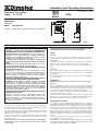
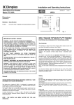
Exploded view of
Terminal Block
Fig. 2
C
L
1.
2.
3.
4.
5.
6.
7.
8.
9.
Remove the top cover from the appliance by removing the two
screws securing the top cover and hinging it back.
Mark the position of the keyhole slots on the wall and drill and plug
for the two suitable screws.
Partially insert the two screws, then hang the appliance on these
screws and mark the position of the lower centrally positioned
screw.
Remove the appliance and drill and plug for the third screw.
Remount the appliance on the wall, ensure that it is horizontal and
fix in position by tightening all three screws.
Feed the supply cord or wires through the inlet at the top rear of
the appliance leaving sufficient free length to connect to the terminal
block.
Make electrical connections to the terminal block ensuring that the
live connection is made to the terminal marked ‘L’ and the neutral
connection to the terminal marked ‘N’ (see Fig. 2 exploded view).
Operate the selector switch to provide either 1kW or 2kW output.
Replace the top cover and screws.
The appliance is now ready for use and the electricity supply can be
reinstated.
This model has a run-back timer
which can be set on a run time of 5
– 155 minutes. This can be adjusted
by removing the top cover and
moving the jumpers on the timer, e.g.
to run the timer for 65 mins. you leave
the 5, 20 and 40 min jumpers in the
closed position (i.e. the closed
position is when the jumper covers
the two pins on timer), and move the
remaining jumpers to open position
or on one pin only, which provides
no contact between pins. (see Fig.
Fig. 4
4 for setting for 65 mins)
Note: The run-back period defaults to 15 minutes when all jumpers are in
the open position.
At the end of a timer run-back period, the appliance can be restarted by
pulling the cord twice; the red neon light will extinguish after the first pull,
and will light up again after the second pull.
Cleaning and User Maintenance
WARNING
BEFORE UNDERTAKING CLEANING OR MAINTENANCE WORK ON THE
APPLIANCE DISCONNECT THE ELECTRICITY SUPPLY BY SWITCHING
OFF AT THE ADJACENT DOUBLE POLE SWITCH.
The outside can be cleaned by wiping it over with a soft damp cloth and
then dried. Do not use abrasive cleaning powders or furniture polish as
this can damage the surface finish.
Ensure that dust or fluff does not accumulate inside the heater as this
could lead to overheating of the element. Use a vacuum cleaner to remove
any fluff which does accumulate.
Recycling
For electrical products sold within the European Community.
At the end of the electrical products useful life it should not
be disposed of with household waste. Please recycle where
facilities exist. Check with your Local Authority or retailer for
recycling advice in your country.
Neon
H3
H2
M1A
H1A
S1
After Sales Service
Terminal Block
If this product appears damaged when first received or does not
function correctly contact us by e-mail [email protected] or
ring 0844 879 35 88 and we will be able to help. For ROI please phone
018424833.
Motor
N
L
Do Not Return the product in the first instance as this may delay us
providing you with a satisfactory service.
ACCIDENTAL DAMAGE IS NOT COVERED UNDER THE WARRANTY.
1000W
Your product is guaranteed for two years from the date of purchase.
Within this period, we undertake to repair this product free of charge
provided it has been installed and operated in accordance with these
instructions.
1000W
Element
WIRING DIAGRAM - FX20VE
Fig. 3
Should you require assistance with this product please go to
www.dimplex.co.uk and click on “Customer Support” or e-mail us at
[email protected]
Alternatively ring our contact centre on 0844 879 35 88 (UK only). This
is a Lo-call no. from a BT landline - other providers including mobile
phones may charge you more. For ROI please phone 01 842 4833.
Controls
The cut-out is a safety device which switches off the heater and fan if
for any reason the appliance overheats - see ‘Safety’.
The thermal fuse link is provided as an added safety feature, and
operates to open circuit if there is abnormal overheating within the
appliance. The operation of these safety devices is described under
‘Safety’.
To assist you, we will need the following information: model number &
serial no (these can be found on the product), nature of the fault & date
of purchase. Please retain your receipt as proof of purchase. Your
rights under this guarantee are additional to your statutory rights, which
in turn are not affected by this guarantee.
Spares can be purchased on line, go to www.dimplex.co.uk/outlet_store
The product complies with the European Safety Standards EN60335-2-30 and the European Standard Electromagnetic Compatibility (EMC)
EN55014, EN60555-2 and EN60555-3. These cover the essential requirements of EEC Directives 2006/95/EC and 2004/108/EC
Dimplex UK Ltd.
Millbrook House
Grange Drive
Hedge End
Southampton
Hampshire. SO30 2DF
UK customer help line 8.00am–5.00pm Mon-Fri and 8:30am-1.00pm Sat (October-March)
Technical Services:
Tel.
0844 870 3588
Fax.
0844 879 3582
e-mail [email protected]
Republic of Ireland
Tel.
01 842 4833
[c] Dimplex UK Limited
All rights reserved. Material contained in this publication may not be reproduced in whole or in part, without prior permission in writing of Dimplex UK Limited.