1
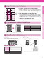
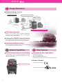
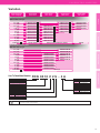
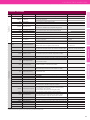
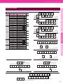
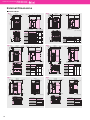
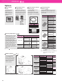
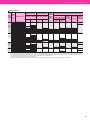
Compact inverter
COMPACT
INVERTER
FRENIC
FUJI ELECTRIC
INVERTERS
High Perfomance
Compact Body
Welcome to the
NEXT Generation
of Compact Inverters
New
Compact
And
High
Perfomance
NEXT
Generation!
24A1-E-0011d
High Performance
and
Multipurpose
Fully Compatible
with
Existing Products
Easy Operation
and
Maintenance
New Compact Inverter
High Performance Compact Body.
Get Our Most User-Friendly Inverter yet!
NEXT Generation!
COMPACT
INVERTER
FRENIC
FUJI ELECTRIC INVERTERS
High Perfomance Compact Body.
Welcome to the NEXT Generation of Compact Inverter
With its functionality, compact design, simple operation, and global compatibility,
the new FRENIC-Mini elevates the performance of a wide range of devices and equipment--including conveyors,
fans, pumps, centrifugal separators, and food processing machines--to give you the system integration,
energy efficiency, reduced labor, and lower overall costs you're looking for.
Energy
Efficient
2
Network
Capabilities
Global
Compatibility
FUJI ELECTRIC INVERTERS
High Perfomance Compact Body Welcome to the NEXT Generation of Compact Inverters
High Performance and Multipurpose
Fuji Electric original dynamic torque vector control system is known for its
top-of-the line performance, delivering stabile torque output even at low
speeds. This feature has a wide range of applications, including conveyors
and high-inertia loads that demand high starting torque.
5Hz
100
10Hz
Motor
speed
[r/min]
0
-100
Slip Compensation shortens setting time
The slip compensation controller works with voltage tuning for even more
accurate speed control at low velocity. This reduces speed control variability
and stabilizing creep speed for more accurate stopping in conveyors and
similar equipment.
Specifications
200
Fastest CPU Processor in its Class
-200
Advanced CPU processes data at twice the speed of our current model
Full Compatibility and User Friendly Design
120
(4.72)
New C2 model
120
(4.72)
External dimensions
Interchangeable
Installed dimensions
Interchangeable
Number of terminals
Same for both main circuit and controllers
Terminal position
Compatible terminal wire length
Function codes
Compatible function codes
RS-485 communication
Shared communications protocol
Terminal Functions
Current C1 model
80(3.15)
80(3.15)
Note: Three-phase 200V 0.1– 0.75kW dimensions shown (mm(inch))
External Dimensions
Output torque [%]
Features
Dynamic Torque Vector Control System
3Hz
Easy Operation and Maintenance
Usability
USB Keypad
Delivers all the usability of the C1. Provides volume of frequency
and the same ease of operation as the current model.
Optional USB keypad available. Enhanced PC loader
software (FRENIC Loader) connectivity.
Improve Maintainability
USB-USB mini-B cable
LAN cable
Function
Description
Mock malfunction
Select a function to set off a mock alarm
Number of startups
Count the total number of ON/OFF run cycles
Cumulative motor running time
Monitor motor run time
Total power
Set to measure total power consumption
Trip history
Saves and displays information on up to four past trips
· FRENIC Loader available as a free download
3
COMPACT INVERTER
FRENIC-
Energy Optimization
Optimum Energy Control
Motor tuning minimizes power loss
Way of thinking about the power used
Current FRENIC-Mini
Optimum control
of overall system
Power supply
Optimum
motor control
Power supply
New control system (New FRENIC-Mini)
PID Control Function
Permits motor operation while controlling temperature,
pressure, and flow rate without the use of a temperature
controller or other external device
Cooling Fan ON/OFF Control Function
The cooling fan can be switched off when the fan or pump is
not running to reduce both noise and energy consumption
Synchronous Motor Control
Use of sensorless synchronous motor control together with
the motor can reduce energy consumption
Network Capabilities
Other
Other Features
RS-485 Communications Port as Standard
Functions for User Applications
Communications can be controlled through the standard
RS-485 communications port using the Modbus-RTU or Fuji
Electric inverter protocol
V/F (non-linear 3 step)
Two motor parameter sets
Brake signal (brake release signal)
Rotational direction control (prevent forward/reverse movement)
Global Standard
EC Directives (CE making)
RS-485 Communication Port
UL standard (cUL certification)
4
FUJI ELECTRIC INVERTERS
High Perfomance Compact Body Welcome to the NEXT Generation of Compact Inverters
Variation
Three-phase
200V series
Nominal Applied
Motor (kW)[HP]
Three-phase
400V series
Single-phase
100V series
Single-phase
200V series
Features
Standard specifications
0.1 [1/8]
FRN0001C2S-2
FRN0001C2S-7
FRN0001C2S-6U
0.2 [1/4]
FRN0002C2S-2
FRN0002C2S-7
FRN0002C2S-6U
0.4 [1/2]
FRN0004C2S-2
FRN0002C2S-4
FRN0004C2S-7
FRN0003C2S-6U
0.75 [1]
FRN0006C2S-2
FRN0004C2S-4
FRN0006C2S-7
FRN0005C2S-6U
1.5 [2]
FRN0010C2S-2
FRN0005C2S-4
FRN0010C2S-7
2.2 [3]
FRN0012C2S-2
FRN0007C2S-4
FRN0012C2S-7
3.7 [5]
FRN0020C2S-2
FRN0011C2S-4
5.5 [7.5]
FRN0025C2S-2
FRN0013C2S-4
7.5 [10]
FRN0033C2S-2
FRN0018C2S-4
11 [15]
FRN0047C2S-2
FRN0024C2S-4
15 [20]
FRN0060C2S-2
FRN0030C2S-4
Destination
A(Asia), U(USA)
Specifications
Without EMC filter type
U(USA)
A(Asia), C(China), E(Europe), U(USA)
Semi-standard specifications
EMC filter built-in type
FRN0001C2E-7E
0.1 [1/8]
0.4 [1/2]
FRN0002C2E-4E
FRN0004C2E-7E
0.75 [1]
FRN0004C2E-4E
FRN0006C2E-7E
1.5 [2]
FRN0005C2E-4E
FRN0010C2E-7E
2.2 [3]
FRN0007C2E-4E
FRN0012C2E-7E
3.7 [5]
FRN0011C2E-4E
5.5 [7.5]
FRN0013C2E-4E
7.5 [10]
FRN0018C2E-4E
11 [15]
FRN0024C2E-4E
15 [20]
FRN0030C2E-4E
Destination
Series Name
FRENIC series
Applicable Current Rating
This value shows an amperage rating
0001∼0060
Code
C
Application Range
Compact
Code
2
Developed Inverter Series
2-series
Code
S
E
Enclosure
Standard (IP20) (UL Open Type)
EMC filter built-in type
Caution
External Dimensions
E(Europe)
How To Read Model Number
Code
FRN
Terminal Functions
FRN0002C2E-7E
0.2 [1/4]
F RN 00 1 0 C 2 S - 4 A
Code
A
C
E
U
Destination/Manual
Asia/English
China/Chinese
Europe/English
USA/English
Code
2
4
6
7
Input Power Source
Three-phase 200V
Three-phase 400V
Single-phase 100V
Single-phase 200V
The contents of this catalog are provided to help you select the product model that is best for you. Before actual use, be sure to read the User’s Manual
thoroughly to assure correct operation.
5
COMPACT INVERTER
FRENIC-
Standard Model
Specifications
Three-phase 200V series
Item
Specifications
Three-phase 200V
Input power source
FRN
Type
(FRN
C2S-2
,
C2S-2A, FRN
C2S-2U
=A, U)
0002
0004
0006
0010
0012
0020
0025
0033
0047
0060
=A)
0.1
0.2
0.4
0.75
1.5
2.2
3.7
5.5
7.5
11
15
Nominal applied motor[HP](
=U)
1/8
1/4
1/2
1
2
3
5
7.5
10
15
20
Rated capacity[kVA]
0.30
0.57
1.3
2.0
3.5
4.5
7.2
9.5
12
17
22
Rated voltage[V]
Three-phase 200 to 240V (With AVR)
Rated current[A](*1)
0.8(0.7)
5.5(4.2)
9.2(7.0)
12.0(10.0)
19.1(16.5)
25.0(23.5)
33.0(31.0)
47.0(44.0)
60.0(57.0)
Overload capability
150% of rated current for 1min
150% of rated current for 1min or 200% of rated current for 0.5s (If the rated current is in parenthesis)
Rated frequency[Hz]
50, 60Hz
Phases, Voltage, Frequency
Three-phase, 200 to 240V, 50/60Hz
Voltage/Frequency variations
Voltage: +10 to -15% (Voltage unbalance : 2% or less), Frequency: +5 to -5%
Rated current[A] (with DCR)
Braking
Input ratings
Output ratings
0001
Nominal applied motor[kW](
1.5(1.4)
3.5(2.5)
150% of rated current for 1min or
200% of rated current for 0.5s
0.57
0.93
1.6
3.0
5.7
8.3
14.0
21.1
28.8
42.2
57.6
(without DCR)
1.1
1.8
3.1
5.3
9.5
13.2
22.2
31.5
42.7
60.7
80.0
Required power supply capacity[kVA]
0.2
0.3
0.6
1.1
2.0
2.9
4.9
7.4
10
15
20
Torque[%]
150
50
30
DC injection braking
Starting frequency: 0.0 to 60.0Hz, Braking time: 0.0 to 30.0s Braking level: 0 to 100%
Braking transistor
−
3.1(6.8)
4.5(9.8)
4.5(9.8)
100
20
Built-in
Applicable safety standards
UL508C, EN 61800-5-1:2007
Enclosure (IEC 60529)
IP20 (IEC 60529:1989) / UL open type (UL50)
Cooling method
Natural cooling
Weight / Mass[kg(Ibs)]
0.6(1.3)
Fan cooling
0.6(1.3)
0.7(1.5)
0.8(1.8)
1.7(3.7)
1.7(3.7)
2.5(5.5)
3.1(6.8)
*1 The load shall be reduced so that the continuous operating current is the rated current in parenthesis or less if the carrier frequency is set to 3kHz or above or ambient temperature exceeds 40℃ (104℉).
Three-phase 400V series
Item
Specifications
Three-phase 400V
Input power source
FRN
C2S-4A, FRN
=A, C, E, U) FRN
C2S-4E, FRN
Type
(FRN
C2S-4 ,
Nominal applied motor[kW]
(
Output ratings
Input ratings
C2S-4U
0002
0004
0005
0007
0011
0.4
0.75
1.5
2.2
3.7(
=A, C)
4.0(
=E)
=A, C, E)
Nominal applied motor[HP](
Braking
C2S-4C
=U)
0013
0018
0024
0030
5.5
7.5
11
15
1/2
1
2
3
5
7.5
10
15
20
Rated capacity[kVA]
1.3
2.3
3.2
4.8
8.0
9.9
13
18
22
Rated voltage[V]
Three-phase 380 to 480V (With AVR)
Rated current[A](*1)
1.8(1.5)
6.3(5.5)
10.5(9.0)
13.0
18.0
24.0
30.0
Overload capability
150% of rated current for 1min
150% of rated current for 1min or 200% of rated current for 0.5s (If the rated current is in parenthesis)
Rated frequency[Hz]
50, 60Hz
Phases, Voltage, Frequency
Three-phase, 380 to 480V, 50/60Hz
Voltage/Frequency variations
Voltage: +10 to -15% (Voltage unbalance : 2% or less), Frequency: +5 to -5%
Rated current[A] (with DCR)
3.1(2.5)
4.3(3.7)
150% of rated current for 1min or
200% of rated current for 0.5s
0.85
1.6
3.0
4.4
7.3
10.6
14.4
21.1
28.8
(without DCR)
1.7
3.1
5.9
8.2
13.0
17.3
23.2
33.0
43.8
Required power supply capacity[kVA]
0.6
1.1
2.0
2.9
4.9
7.4
10
15
20
Torque[%]
100
50
30
DC injection braking
Starting frequency: 0.0 to 60.0Hz, Braking time: 0.0 to 30.0s Braking level: 0 to 100%
Braking transistor
Built-in
3.1(6.8)
4.5(9.8)
4.5(9.8)
Applicable safety standards
UL508C, EN 61800-5-1:2007
Enclosure (IEC 60529)
IP20 (IEC 60529:1989) / UL open type (UL50)
Cooling method
Natural cooling
Weight / Mass[kg(Ibs)]
1.2(2.6)
20
Fan cooling
1.3(2.9)
1.7(3.7)
1.7(3.7)
2.5(5.5)
3.1(6.8)
*1 The load shall be reduced so that the continuous operating current is the rated current in parenthesis or less if the carrier frequency is set to 3kHz or above or ambient temperature exceeds 40℃ (104℉).
6
FUJI ELECTRIC INVERTERS
High Perfomance Compact Body Welcome to the NEXT Generation of Compact Inverters
Specifications
Single-phase 200V/100V series
Specifications
Single-phase 200V
Type
FRN
C2S-7A, FRN
C2S-7C
FRN
C2S-7E, FRN
C2S-7U
0001
0002
0004
0006
0010
0.1
0.2
0.4
0.75
1.5
(FRN
C2S-
,
=A, C, E, U)
Nominal applied motor[kW]
C2S-6U
0012
0001
0002
0003
0005
2.2
0.1
0.2
0.4
0.75
=U)
1/8
1/4
1/2
1
2
3
1/8
1/4
1/2
1
Rated capacity[kVA]
0.30
0.57
1.3
2.0
3.5
4.5
0.26
0.53
0.95
1.6
Rated voltage[V]
Three-phase 200 to 240V (With AVR)
Rated current[A](*1)
0.8(0.7)
5.5(4.2)
9.2(7.0)
12.0(10.0)
0.7
1.4
2.5
4.2
Overload capability
150% of rated current for 1min
150% of rated current for 1min or 200% of rated current for 0.5s (If the rated current is in parenthesis)
Rated frequency[Hz]
50, 60Hz
Phases, Voltage, Frequency
Single-phase, 200 to 240V, 50/60Hz
Voltage/Frequency variations
Voltage: +10 to -10%, Frequency: +5 to -5%
Rated current[A] (with DCR)
1.5(1.4)
3.5(2.5)
150% of rated current for 1min
or 200% of rated current for 0.5s
Single-phase 100 to 120V, 50/60Hz
1.1
2.0
3.5
6.4
11.6
17.5
2.2
3.8
6.4
12.0
(without DCR)
1.8
3.3
5.4
9.7
16.4
24.0
3.6
5.9
9.5
16.0
Required power supply capacity[kVA]
0.3
0.4
0.7
1.3
2.4
3.5
0.3
0.5
0.7
1.3
Torque[%]
150
50
30
150
DC injection braking
Starting frequency: 0.0 to 60.0Hz, Braking time: 0.0 to 30.0s, Braking level: 0 to 100%
Braking transistor
−
100
Built-in
UL508C
UL508C, EN 61800-5-1:2007
Enclosure (IEC 60529)
IP20 (IEC 60529:1989) / UL open type (UL50)
Cooling method
Natural cooling
Weight / Mass[kg(Ibs)]
0.6(1.3)
Fan cooling
0.7(1.5)
100
−
Built-in
Applicable safety standards
0.6(1.3)
Specifications
Output ratings
Input ratings
FRN
=A, C, E)
Nominal applied motor[HP](
Braking
Single-phase 100V
Terminal Functions
(
Features
Item
Input power source
0.9(2)
1.8(4)
Natural cooling
2.5(5.5)
0.7(1.5)
0.7(1.5)
0.8(1.8)
1.3(2.9)
External Dimensions
*1 The load shall be reduced so that the continuous operating current is the rated current in parenthesis or less if the carrier frequency is set to 3kHz or above or ambient temperature exceeds 40℃ (104℉).
7
COMPACT INVERTER
FRENIC-
EMC Filter Built-in Model
Specifications
Three-phase 400V series
Item
Specifications
Input power source
Three-phase 400V
Type
FRN
C2E-4E
0002
0004
0005
0007
0011
0013
0018
0024
0030
Nominal applied motor[kW]
0.4
0.75
1.5
2.2
4.0
5.5
7.5
11
15
Nominal applied motor[HP]
1/2
1
2
3
5
7.5
10
15
20
Rated capacity[kVA]
1.3
2.3
3.2
4.8
8.0
9.9
13
18
22
Rated voltage[V]
Three-phase 380 to 480V (With AVR)
Rated current[A](*1)
1.8(1.5)
6.3(5.5)
10.5(9.0)
13
18
24
30
Overload capability
150% of rated current for 1min
150% of rated current for 1min or 200% of rated current for 0.5s (If the rated current is in parenthesis)
Rated frequency[Hz]
50, 60Hz
Phases, Voltage, Frequency
Three-phase, 380 to 480V, 50/60Hz
Braking
Input ratings
Output ratings
(FRN
C2E-4E)
3.1(2.5)
4.3(3.7)
150% of rated current for 1min or
200% of rated current for 0.5s
Voltage/Frequency variations
Voltage: +10 to -15% (Voltage unbalance : 2% or less), Frequency: +5 to -5%
Rated current[A] (with DCR)
0.85
1.6
3.0
4.4
7.3
10.6
14.4
21.1
28.8
(without DCR)
1.7
3.1
5.9
8.2
13.0
17.3
23.2
33.0
43.8
Required power supply capacity[kVA]
0.6
1.1
2.0
2.9
4.9
7.4
10
15
20
Torque[%]
100
50
30
DC injection braking
Starting frequency: 0.0 to 60.0Hz, Braking time: 0.0 to 30.0s Braking level: 0 to 100%
Braking transistor
Built-in
Applicable safety standards
UL508C, EN 61800-5-1:2007
Applicable EMC standards
(EN61800-3:2004 +A1:2012)
(in progress)
Immunity : Second Environment (Industrial)
Emission : Category C2
Enclosure (IEC 60529)
IP20 (IEC 60529:1989) / UL open type (UL50)
Cooling method
Natural cooling
Weight / Mass[kg(Ibs)]
1.5(3.3)
20
Immunity : Second Environment (Industrial)
Emission : Category C3
Fan cooling
1.6(3.5)
3.0(6.6)
3.1(6.8)
3.2(7.1)
4.6(10.1)
4.6(10.1)
6.7(15)
6.7(15)
*1 The load shall be reduced so that the continuous operating current is the rated current in parenthesis or less if the carrier frequency is set to 3kHz or above or ambient temperature exceeds 40℃ (104℉).
Single-phase 200V series
Item
Specifications
Single-phase 200V
Input power source
FRN
Type
0002
0004
0006
0010
0012
Nominal applied motor[kW]
0.1
0.2
0.4
0.75
1.5
2.2
Nominal applied motor[HP]
1/8
1/4
1/2
1
2
3
Rated capacity[kVA]
0.30
0.57
1.3
2.0
3.5
4.5
Rated voltage[V]
Single-phase, 200 to 240V, 50/60Hz
Rated current[A](*1)
0.8(0.7)
3.5(2.5)
5.5(4.2)
9.2(7.0)
12.0(10.0)
Overload capability
150% of rated current for 1min
150% of rated current for 1min or 200% of rated current for 0.5s (If the rated current is in parenthesis)
Rated frequency[Hz]
50, 60Hz
Phases, Voltage, Frequency
Single-phase, 200 to 240V, 50/60Hz
Input ratings
Braking
C2E-7E)
C2E-7E
0001
Output ratings
(FRN
1.5(1.4)
Voltage/Frequency variations
Voltage: +10 to -10%, Frequency: +5 to -5%
Rated current[A] (with DCR)
1.1
2.0
3.5
6.4
11.6
17.5
(without DCR)
1.8
3.3
5.4
9.7
16.4
24.0
Required power supply capacity[kVA]
0.3
0.4
0.7
1.3
2.4
3.5
Torque[%]
150
50
30
DC injection braking
Starting frequency: 0.0 to 60.0Hz, Braking time: 0.0 to 30.0s, Braking level: 0 to 100%
Braking transistor
−
100
Built-in
Applicable safety standards
UL508C, EN 61800-5-1:2007
Applicable EMC standards
(EN61800-3:2004 +A1:2012)
(in progress)
Immunity : Second Environment (Industrial)
Emission : Category C2
Enclosure (IEC 60529)
IP20 (IEC 60529:1989) / UL open type (UL50)
Cooling method
Natural cooling
Weight / Mass[kg(Ibs)]
0.7(1.5)
Fan cooling
0.7(1.5)
0.8(1.8)
1.2(2.6)
3.0(6.6)
3.0(6.6)
*1 The load shall be reduced so that the continuous operating current is the rated current in parenthesis or less if the carrier frequency is set to 3kHz or above or ambient temperature exceeds 40℃ (104℉).
8
FUJI ELECTRIC INVERTERS
High Perfomance Compact Body Welcome to the NEXT Generation of Compact Inverters
Common Specifications
Common Specifications
Base frequency
25 to 400Hz
Starting frequency
0.1 to 60.0Hz
Carrier frequency
0.75 to 16kHz
Note: The unit is equipped with an automatic reduction/stop function that may automatically drop the carrier frequency to
protect the inverter when it is running at frequencies above 6 kHz, depending on ambient temperature, output current, and
other conditions. (*1)
· Under modulated carrier conditions, the system scatters carrier frequency to reduce noise
Accuracy (stability)
· Analog setting:
· Keypad setting:
: Absolute accuracy within ± 2% (at 25℃(77℉)), temperature drift within ± 0.2% (25℃(77℉) ± 10℃(50℉))
: Absolute accuracy within ± 0.01% (at 25℃(77℉)), temperature drift within ± 0.01% (25℃(77℉) ± 10℃(50℉))
Setting resolution
· Analog setting
· Keypad setting
· Link operation
: 1/1000 of maximum frequency
: 0.01Hz (99.99Hz or less), 0.1Hz (100.0Hz to 400.0Hz)
: 1/20000 of maximum frequency or 0.01Hz (fixed)
Control method
Remarks
Features
Explanation
25 to 400Hz
Specifications
Setting range
Output frequency
Item
Maximum frequency
Induction motor drive
· V/f control · Slip compensation · Automatic torque boost
· Dynamic torque vector control · Automatic energy-saving function
200V series
Base frequency and maximum output frequency can each be set between :80 to 240
AVR control (*1) can be turned ON or OFF
Allowable non-linear V/f (*1) settings (2): optional voltage (0–240V) and frequency (0–400Hz)
400V series
Base frequency and maximum output frequency can each be set between :160 to 500
AVR control (*1) can be turned ON or OFF
Allowable non-linear V/f (*1) settings (2): optional voltage (0–500V) and frequency (0–400Hz)
Voltage/freq. characteristic
Terminal Functions
Synchronous motor drive
· Sensorless magnetic positioning (speed control range: 10% of base frequency and up)
· Automatic torque boost (for constant torque loads)
Torque boost (*1)
· Manual torque boost: Optional torque boost value can be set between 0.0 and 20.0%
· Application load can be selected (for constant and variable torque loads)
150% or more/frequency set to 3Hz Slip compensation /automatic torque boost active
Keypad operation
Control
Start/stop
: Start and stop with
,
keys (standard keypad)
: Start and stop with
,
keys (remote keypad: optional)
External signals
(digital input)
: FWD (REV) operation/stop command [3-wire operation enabled]
Coast-to-stop command, trip command (external fault), fault reset, etc.
Link operation
: Communication via RS-485
External Dimensions
Starting torque (*1)
Changing run command : Communications used to change run command
Keypad operation
: Can be set with
or
key (with save data function)
Also can be set with function code (only via communication) and be copied.(*2)
Set based on built-in volume
Analog input
Frequency setting
Multistep frequency
: 0 to +10V DC/0 to 100% (terminal 12)
: 4 to +20mA DC/0 to 100%, 0 to +20mA DC/0 to 100% (terminal C1)
: Selectable from 16 steps (step 0 to 15)
UP/DOWN operation
: Raises or lowers frequency while digital input signal is ON
Link operation:
: Frequency set through RS-485 communication
Changing frequency settings
: Two types of frequency settings can be changed using external signals (digital input) : frequency
settings and multistep frequency settings
Auxiliary frequency setting : Built-in potentiometer, Inputs at terminal 12, C1 can be added to the main setting as auxiliary frequency settings.
Inverse operation
Acceleration/deceleration time
: Can be switched from (DC 0 to +10V/0 to 100%) to (DC +10 to 0V/0 to 100%) externally
: Can be switched from (DC 4 to 20mA (DC 0–20mA)/0 to 100%) to (DC 20 to 4mA (DC 20–0mA)/0 to 100%) externally
· Can be set between 0.00 and 3600s
· There are two independent settings that can be selected for acceleration/deceleration time (can be switched while running)
· Pattern : The following four acceleration/deceleration types can be selected
Linear, S-curve (weak/strong), non-linear (constant output maximum capacity acceleration/deceleration)
· Coast-to-stop acceleration/deceleration is enabled when run commands are OFF
· Acceleration/deceleration time can be set during jogging operation (between 0.00 and 3600s)
*1 Only valid when induction motor drive is in operation
9
COMPACT INVERTER
FRENIC-
Common Specifications
Common Specifications
Explanation
High and low limiters can be set in addition to Hz values (0–400Hz)
Bias frequency
Bias of set frequency and PID command can be set separately between 0 and ±100%
Analog input gain can be set between 0 and 200%
Jump frequency control
Three operation points and their common jump hysteresis width can be set (0–30Hz)
Six operation points and their common jump hysteresis width can be set (0–30Hz) (*2)
Timer operation
Operation starts and stops at the time set from keypad (1 cycle)
Jogging operation (*1)
Operated using the
key (on the standard or remote keypad) or digital contact point input
(acceleration and deceleration time--same duration used only for jogging)
Auto-restart after momentary
power failure (*1)
・Trip at power failure: The inverter trips immediately after power failure.
・Trip at power recovery: Coast-to-stop at power failure and trip at power recovery
・Deceleration stop: Deceleration stop at power failure, and trip after stoppage (*2)
・Start at the frequency selected before momentary stop: Coast-to-stop at power failure and start after power recovery at
the frequency selected before momentary stop.
・Start at starting frequency: Coast-to-stop at power failure and start at the starting frequency after power recovery.
Current limit
by hardware (*1)
Uses hardware to limit current and prevent overcurrent trips resulting from sudden load changes, momentary power failures,
and similar events that cannot be handled by software current limiters (can be canceled)
Slip compensation (*1)
Compensates for decrease in speed according to the load, enabling stable operation
Current limit
Keeps the current under the preset value during operation
PID control
Process PID regulator
· PID command, keyboard, analog input (terminal 12, C1), RS-485 communication
· Feedback value: Analog input (terminal 12, C1)
· Low liquid level stop function · Switch forward/reverse operation · Integration reset/hold function
Automatic deceleration
· Automatically limits output frequency, limits energy generated by the inverter, and avoids overcurrent trips when torque relay value is exceeded (*1)
· Makes deceleration time three times longer to avoid
trip when DC link circuit voltage exceeds overage limit
Deceleration characteristics
(improved braking capacity)
Increases motor loss and reduces energy generated by the inverter during deceleration to avoid overcurrent trips
Energy saving operation (*1)
Restricts output voltage to minimize total motor and inverter loss during constant speed operation
Overload prevention control
Lowers frequency when IGBT junction temperature and ambient temperature rise due to overloading to avoid further overload
Offline tuning (*1)
Performs r1, Xσ, and excitation current tuning
Performs r1, Xσ, slip frequency and excitation current tuning (*2)
Fan stop operation
Detects inverter internal temperature and stops cooling fan when the temperature is low
Secondary motor settings
· Switching between two motors in the same inverter is enabled (switching cannot be performed while the inverter is running)
Induction motor settings can only be applied to the second motor
Data settings (base frequency, rated current, torque boost, electronic thermal, and slip compensation, etc.) can be entered for the second motor
· Constants can be set within the second motor. Auto-tuning is also enabled.
Rotational direction limits
Select either prevent reverse or prevent forward operation
Running/stopping
Speed monitor, output current [A], output voltage [V], input power [kW], PID reference, PID feedback value, PID output, timer
value (for timer operation) [s], total power amount
Select the speed monitor to be displayed from the following:
Output frequency (before slip compensation) [Hz], output frequency (after slip compensation) [Hz], set frequency [Hz],
load shaft speed [min-1], line speed [m/min], constant rate of feeding time [min]
Lifetime alarm
Displays the lifetime alarm for the main circuit condenser, PCB condenser, and cooling fan. External output is enabled for lifetime alarm information.
Total running time
Can display total motor running time, total inverter running time, and total power use
I/O check
Displays control circuit terminal output status
Energy saving monitor
Power consumption, power consumption x coefficient
Trip mode
Displays cause of trip:
·
: Overcurrent during acceleration ·
: Overcurrent during deceleration
·
: Input phase loss
·
: Undervoltage
: Overvoltage during deceleration
·
: Overvoltage during acceleration ·
·
: Overheating of the heat sink ·
: External thermal relay tripped
·
: Overheating of the DB circuit ·
: PID feedback break detected
·
: Overload in motor 2
·
: Inverter unit overload
·
: Keypad communication error ·
: CPU error
·
: Tuning error
·
: RS485 error
·
: Step out detected (for synchronous motor drive) (*2)
Running or Trip mode
Trip history: Saves and displays the last 4 trip codes and their detailed description
Saves and displays detailed data for each section on up to four past trips
*1 Only valid when induction motor drive is in operation
*2 These functions can be supported by the inverters having a ROM version 0500 or later
10
Remarks
Gain for frequency setting
Indication
Control
Item
Frequency limiter
(Peak/bottom frequency limit)
·
·
·
·
·
·
·
·
·
: Overcurrent at constant speed
: Output phase loss
: Overvoltage during constant speed
: Motor protection (PTC thermistor)
: Overload in motor 1
: Memory error
: Operation procedure error
: Data save error due to undervoltage
: Mock error
FUJI ELECTRIC INVERTERS
High Perfomance Compact Body Welcome to the NEXT Generation of Compact Inverters
Common Specifications
Short-circuit
Stops the inverter to protect against overcurrent due to a short circuit in the output circuit
Ground fault
Stops the inverter to protect against overcurrent due to a ground fault (initial ground circuit only) in the output circuit
Overvoltage
Detects excess voltage in DC link circuit (200V: DC 400V,400V: DC 800V) and stops the inverter
Cannot protect against significantly large voltage input mistakenly applied
OU1
OU2
OU3
Undervoltage
Input phase loss
Detects drops in DC link circuit voltage (200V: DC 200V,400V: DC400V) and stops the inverter
Note that no alarm will sound if auto-restart after momentary power failure is selected
Stops or protects the inverter against input phase loss
Even when there is input phase loss, the loss may not be detected if the connected load is light or a DC reactor is connected to the inverter
Lin
OPL
Stops the inverter by detecting the temperature of the inverter cooling system (e.g. when the cooling fan is malfunctioning or there is an overload)
OH1
Protects against overheating during braking resistance based on braking resistor electronic thermal function settings
dbH
Overload
Stops the inverter based on the temperature of the cooling system and the switching element calculated from output current flow
OLU
External alarm input
Stops the inverter alarm through digital input (THR)
OH2
Overheating
Electronic thermal
Protects the standard motor and inverter motor over the full frequency range. The second motor can also be
OL1
OL2
protected. (Operation level and thermal time constant can be set between 0.5 and 75.0 minutes)
· Stops running the inverter to protect the motor when the PTC thermistor detects motor temperature
A PTC thermistor is connected between terminals C1 and 11, and a resistor is connected between terminals 13 and C1. Set function code.
OH4
Outputs a preliminary alarm at a preset level before the electronic thermal stops the inverter
―
Memory error
Checks data when the power is turned on and data is being written, and stops the inverter if a memory malfunction is detected.
Er1
Keypad
communication error
Stops the inverter if a communication malfunction is detected between the keypad and inverter unit while an operation
command is in progress from the remote keypad
Er2
CPU error
Stops the inverter if a CPU malfunction caused by noise or similar factors is detected
Er3
Overload early warning
key priority
Operation error
Start check
Pressing the
key on the keypad forces the inverter to stop, even if run commands are being
delivered via terminals or communications. Er6 is displayed once stop is complete.
Prohibits run operations and displays Er6 if a run command is given while any of the following status changes are occurring:
· Powering up · Canceling an alarm
· Switching run command methods via link operation
Er6
Tuning error (*1)
Stops the inverter when there is a tuning failure, interruption, or abnormality in tuning results during motor constant tuning
Er7
RS-485 communication error
Stops the inverter if a communications malfunction is detected in RS-485 communication with the inverter unit
Er8
Data save error during undervoltage
Displays an error if data save cannot proceed normally because an undervoltage protection function is activated
ErF
Step out detected (*2)
Stops the inverter when a synchronous motor step out is detected
Erd
PID feedback break detected
Stops the inverter when a break is detected during current input (C1 terminal) distribution to PID feedback (can be enabled/disabled)
CoF
Stall prevention
Output frequency is reduced to avoid an overcurrent trip when output current exceeds the limit during acceleration/deceleration or constant speed operation
Alarm output (for any fault)
· Outputs a relay signal when the inverter is stopped due to an alarm
· Alarm stop status can be canceled by pressing the PRG/RESET key or by inputting a digital signal (RST)
Retry
Inverter can be automatically reset and restarted after stopping due to a trip (the number of retries and wait time until reset can also be set)
Incoming surge
Protects the inverter from surge voltage between the main circuit and ground terminal
Momentary power failure
Mock malfunction
Installation location
Terminal Functions
PTC thermistor
External Dimensions
Motor protection
Stops running the inverter to protect the motor according to electronic thermal function settings
Protection
LU
Detects loss from breaks in output wiring while running or during startup and stops the inverter
Output phase loss detected
Environment
Remarks
LED display
OC1
OC2
OC3
Features
Explanation
Stops the inverter to protect against overcurrent due to overload
Specifications
Item
Overcurrent
· Launches a protective function (stops the inverter) when there is a momentary power failure of 15ms or more
· Restarts and restores voltage within the set time when momentary power failure restart is selected
Can output a mock alarm to check malfunction sequences
Err
· Must be indoors and free of corrosive gases, flammable gases, dust, and oil mist (contamination level 2 (IEC 60664-1: 2007)
· Keep out of direct sunlight
Ambient temperature
Open: –10℃ (14°F) to + 50℃ (122°F) (IP20)
Ambient humidity
5 to 95%RH (no condensation)
Altitude
1000m (3300ft) or less (Output derating is not necessary.)
Above 1000m (3300ft) to 3000m (9800ft) or less (Output derating is necessary.)
Above 1000m (3300ft) to 1500m (4900ft) or lower : 0.97, Above 1500m (4900ft) to 2000m (6600ft) or lower : 0.95,
Above 1000m (3300ft) to 2500m (8200ft) or lower : 0.91, Above 2500m (8200ft) to 3000m (9800ft) lower : 0.88
Vibration
3mm (0.12inch) (vibration width): 2 to less than 9Hz, 9.8m/s2: 9 to less than 20Hz, 2m/s2: 20 to less than 55Hz, 1m/s2: 55 to less than 200Hz
Saved temperature
-25℃ (77°F) ± 70℃ (158℉)
Saved humidity
5 to 95%RH (no condensation)
*1 Only valid when induction motor drive is in operation
*2 These functions can be supported by the inverters having a ROM version 0500 or later
11
COMPACT INVERTER
FRENIC-
Terminal Functions
Terminal Functions
Main circuit
Category
Symbol
Terminal Name
Functions
Remarks
L1/R,L2/S,L3/T
Power input
Connect a three-phase power supply (three-phase 200V,400V)
U,V,W
Inverter output
Connect a three-phase induction motor
P(+) ,P1
For DC REACTOR
Connect the DC REACTOR
P(+) ,N(-)
For DC bus connection
Used for DC bus connection system
P(+) ,DB
For EXTERNAL
BRAKING RESISTOR
Connect external braking resistor
Grounding
Ground terminal for inverter chassis
Potentiometer power supply
Power supply for frequency setting potentiometer (1 to 5kΩ)
Voltage input
· Used as voltage input for frequency setting
0 to +10V DC/0 to 100%
(Inverse operation)
(PID control)
(Frequency aux. setting)
· +10 to +0V DC/0 to 100%
· Used for reference signal (PID process command) or feedback signal
· Used as additional auxiliary setting to various main settings of frequency
Current input
· Used as current input for frequency setting
+4 to +20mA DC (0 to +20mA DC)/0 to 100%
(Inverse operation)
(PID control)
(Frequency aux. setting)
· +4 to +20mA DC (0 to +20mA DC)/0 to 100%
G(2-terminal)
13
Frequency setting
12
C1
Only for 0.4kW and above. Connections are enabled
for 0.2kW and below, but operation will not work.
DC10V
· Used for reference signal (PID process command) or feedback signal
· Used as additional auxiliary setting to various main settings of frequency
(For PTC thermistor)
· Connects PTC thermistor for motor protection
11(2-terminal)
Common
Common terminal for frequency setting signal (12, 13, C1, FMA)
X1
Digital input 1
X2
Digital input 2
X3
Digital input 3
FWD
Forward operation command
REV
Reverse operation command
The following functions can be set at terminals X1 to X3, FWD,
and REV for signal input.
- Common function
· Switch between synch/source using the built-in switches on the unit
· Short-circuit ON or open circuit ON settings are enabled between the terminal X1 and CM
The same setting is possible between CM and any of the terminals among X2, X3, FWD, and REV.
Isolated from terminal CM and Y1E
(FWD)
Forward operation command
The motor runs in the forward direction when (FWD) is ON, stops after
deceleration when FWD is OFF
Only terminal FWD/REV settings are
allowed, only short circuit ON
(REV)
Reverse operation command
The motor runs in the reverse direction when (REV) is ON, stops after deceleration when REV is OFF
do.
16-speed operation is enabled using the ON/OFF signal from (SS1)
through (SS8)
(SS1)
(SS2)
(SS4)
Frequency
Multistep freq. selection
Digital input
(SS8)
(RT1)
ACC/DEC selection
(HLD)
3-wire operation stop command
0
1
2
3
4
5
6
7
8
9
10
11
12
13
14
15
(SS1)
-
ON
-
ON
-
ON
-
ON
-
ON
-
ON
-
ON
-
ON
(SS2)
-
-
-
-
ON ON
-
-
-
-
(SS4)
-
-
-
-
ON ON ON ON
-
-
(SS8)
-
-
-
-
Digital input
ON ON
-
-
-
-
ON ON
-
-
ON ON
ON ON ON ON
ON ON ON ON ON ON ON ON
Acceleration/deceleration time setting 1 is active when RT1 is OFF
Acceleration/deceleration time setting 2 is active when RT1 is ON
· Used as an automatic hold signal during 3-wire operation
· The FWD or REV signal is automatically stopped when HLD is ON,
and the hold is removed when HLD is OFF
(BX)
Coast-to-stop command
Alarm reset
Alarm hold status is removed when RST is ON
(THR)
Trip command (External fault)
When THR is OFF, inverter output is shut off immediately and the motor
coasts-to-stop (alarm output enabled: OH2)
(JOG)
Jogging operation
Turn JOG ON to enable jogging operation: switches the running mode
to jogging mode, the frequency setting to jogging frequency, and
acceleration/deceleration time to jogging running use
Freq. set 2/ Freq. set 1
Frequency setting 2 is selected when Hz2/Hz1 is ON
Motor 2/Motor 1
Motor 1 settings take effect when M2/M1 is OFF. Motor 2 settings take effect when M2/M1 is ON.
(RST)
(Hz2/Hz1)
(M2/M1)
*1 Only valid when induction motor drive is in operation
12
When BX is ON, inverter output is shut off immediately and the motor
coasts-to-stop (no alarm output)
Signal at 0.1s or higher
(*1)
FUJI ELECTRIC INVERTERS
High Perfomance Compact Body Welcome to the NEXT Generation of Compact Inverters
Terminal Functions
Turn DCBRK ON to start direct current braking
(WE-KP)
Write enable
for KEYPAD
Function code data changes can only be made when the keypad
is turned ON with WE-KP
UP command
Output frequency increases while UP is ON
(DOWN)
DOWN command
Output frequency decreases while DOWN is ON
(Hz/PID)
PID control cancel
PID control is canceled when Hz/PID is ON
(runs based on multistep frequency/keypad/analog input etc.)
Inverse mode changeover
Switch from analog frequency setting or PID control output signal (frequency setting) operation
mode to forward/reverse operation. Reverse operation enabled when IVS is ON.
Digital input
(UP)
(IVS)
Remarks
Operates according to commands from RS-485 when LE is ON
PID integral/differential reset
Turn PID-RST ON to reset PID integration and differential values
(PID-HLD)
PID integral hold
Turn PID-HLD ON to hold PID differentiation
PLC
PLC terminal
Connect to PLC output signal power supply
Common for 24V power
+24V (22–27V)
Max 50mA
CM(2-terminal)
Common
Common for digital input signal
Isolated from terminal 11 and Y1E
(PLC)
Transistor output power
Power supply for transistor output load (Max: DC 24V DC 50mA)
(Caution: Same terminal as digital input PLC terminal)
Short circuit between terminal CM
and Y1E is used
Y1
Transistor output
Select one of the following signals for output:
Short circuit when ON signal is output or open circuit when ON signal is output
Max. voltage: 27Vdc, max. current: 50mA,
leak current: 0.1mA max., ON voltage: within 2V(at 50mA)
(RUN)
Inverter running (speed exists)
Comes ON when the output frequency is higher than starting frequency
(FAR)
Speed/freq. arrival
Comes ON when the difference between output frequency and set frequency
rises above the frequency arrival detection range (function code E30)
(FDT)
Speed/freq. detection
Comes ON when output frequency falls below operational level (function code E31).
Turns OFF when it falls below operational level (function code E31) or hysteresis width (function code E32).
Undervoltage detection
Comes ON when there is a run command and running has stopped
due to insufficient voltage
(IOL)
Inverter output limit
Comes ON when the inverter is experiencing limited current,
automatic deceleration, or limited torque operation
(IPF)
Auto-restarting
Comes ON during auto restart operation
(after momentary power failure and until completion of restart).
(OL)
Overload early warning
Comes ON when the electronic thermal relay value is higher than
the preset alarm level
Switch to Motor 2
Comes ON when Motor 2 is selected by inputting a motor switch
signal (M2/M1)
(LU)
(SWM2)
(TRY)
Auto-resetting mode
Comes ON during auto reset mode
(LIFE)
Lifetime alarm
Alarm signal is output according to lifetime assessment standards inside the inverter
(PID-CTL)
PID control in progress
Comes ON when PID control is in effect
(PID-STP)
PID low water volume stop in progress
Comes ON when low liquid level stop is in effect in PID control
(also stops based on the status of input run command)
(RUN2)
Inverter output in progress
Comes ON when the inverter is running above startup frequency
and DC braking is also in operation
(Comes ON when the inverter main circuit (gate) is ON)
Overload preventive control
Comes ON when overload prevention control is operating
Current detection 2
Comes ON when a current larger than the set value (for ID2) is
continuously detected for longer than the time set on the timer
(OLP)
(ID2)
(THM)
External Dimensions
Link enable (RS485, Bus)
(PID-RST)
(LE)
Transistor output
Functions
DC brake command
Features
Terminal Name
(DCBRK)
Thermistor detected
Comes ON when motor overheating is detected by the PTC/NTC thermistor
(*1)
Brake signal
Outputs a brake engage/release signal
(*1)
Maintenance timer
Alarm signal is generated when time passes or start-up exceeds over the preset value
(*2)
(FARFDT)
Frequency arrival/frequency detected
Comes ON when both (FAR) and (FDT) are ON
(C1OFF)
C1 terminal break detected
Comes ON when the system determines that a break will occur if terminal C1 input falls below 2mA
Current detection
Comes ON when a current larger than the set value has been detected for the timer-set time
(BRKS)
(MNT)
(ID)
Specifications
Symbol
Terminal Functions
Category
*1 Only valid when induction motor drive is in operation
*2 These functions can be supported by the inverters having a ROM version 0500 or later
13
COMPACT INVERTER
FRENIC-
Terminal Functions
Terminal Functions
LINK
Analog output
Relay output
Transistor output
Category
Symbol
Terminal Name
(IDL)
(ALM)
Y1E
30A, 30B, 30C
FMA
Functions
Small current detection
Comes ON when a current smaller than the set value has been
detected for the timer-set time
Alarm relay (for any fault)
Alarm signal is output as the transistor output signal
Transistor output common
Common terminal for transistor output
Isolated from terminal 11 and CM
Alarm relay output
(for any fault)
Outputs a no-voltage contact signal (1c) when the inverter stops the alarm
Can select the same signal as the Y1 signal for multipurpose
relay output
· Can switch between alarm output through excitation operation and
alarm output through non-excitation operation
Contact rating : AC250V, 0.3A,
cosφ=0.3
DC48V, 0.5A
Analog monitor
Output format: DC voltage (0–10V)
Output can be performed in one of the following selected analog formats
· Output frequency 1 (Before slip compensation)
· Output frequency 2 (After slip compensation)
· Output current
· Output voltage
· Input power
· PID feedback value
· DC link circuit voltage
· Analog output test
· PID command
· PID output
Gain setting between 0 and 300%
Built-in RJ-45 connector
(RS-485 communication)
Any of the following protocols can be selected:
· Dedicated keypad protocol (automatically selected)
· Modbus RTU
· Fuji dedicated inverter protocol
· SX protocol (for PC loader)
Provides power to the keypad
Includes terminator ON/OFF switch
Communication data storage can be
selected.(*2)
*2 These functions can be supported by the inverters having a ROM version 0500 or later
14
Remarks
FUJI ELECTRIC INVERTERS
High Perfomance Compact Body Welcome to the NEXT Generation of Compact Inverters
Terminal Functions
Terminal Arrangement
Main circuit terminals
Inverter Type
Three-phase
400V
Single-phase
200V
Single-phase
100V
L3/T
P1
P(+)
N(-)
FRN0001C2S-2
FRN0002C2S-2
FRN0004C2S-2
FRN0006C2S-2
FRN0010C2S-2
FRN0012C2S-2
FRN0020C2S-2
FRN0025C2S-2
FRN0033C2S-2
FRN0047C2S-2
FRN0060C2S-2
FRN0002C2 -4
FRN0004C2 -4
FRN0005C2 -4
FRN0007C2 -4
FRN0011C2 -4
FRN0013C2S-4
FRN0018C2S-4
FRN0024C2S-4
FRN0030C2S-4
FRN0013C2E-4E
FRN0018C2E-4E
FRN0024C2E-4E
FRN0030C2E-4E
FRN0001C2 -7
FRN0002C2 -7
FRN0004C2 -7
FRN0006C2 -7
FRN0010C2 -7
FRN0012C2 -7
FRN0001C2S-6U
FRN0002C2S-6U
FRN0003C2S-6U
FRN0005C2S-6U
DB
Fig. A
U
V
W
Unit : mm(inch)
G
Screw size: M3.5, Tightening torque: 1.2N.m(10.6 lb-in)
Fig. B
Fig. B
P1
P(+)
U
V
W
N(-)
G
G
Fig. E
DB
L1/R
L2/S
L3/T
Specifications
Three-phase
200V
L2/S
G
Unit : mm(inch)
Screw size: M4, Tightening torque: 1.8N.m(15.9 lb-in)
Fig. F
Fig. C
L1/L
Fig. B
L2/N
P1
P(+)
N(-)
G
DB
U
V
W
Unit : mm(inch)
G
Fig. E
Screw size: M3.5, Tightening torque: 1.2N.m(10.6 lb-in)
Fig. D
Fig. F
DB
P1
P(+)
U
V
W
Terminal Functions
0.1 (1/8)
0.2 (1/4)
0.4 (1/2)
0.75 (1)
1.5 (2)
2.2 (3)
3.7 (5)
5.5(7.5)
7.5(10)
11(15)
15(20)
0.4 (1/2)
0.75 (1)
1.5 (2)
2.2 (3)
3.7 (5)
5.5(7.5)
7.5(10)
11(15)
15(20)
5.5(7.5)
7.5(10)
11(15)
15(20)
0.1 (1/8)
0.2 (1/4)
0.4 (1/2)
0.75 (1)
1.5 (2)
2.2 (3)
0.1 (1/8)
0.2 (1/4)
0.4 (1/2)
0.75 (1)
L1/R
Reference
Features
Fig. A
Nominal Applied
Motor (kW(HP))
N(-)
Fig. G
G
G
L1/L
L2/N
Fig. H
Unit : mm(inch)
Screw size: M4, Tightening torque: 1.8N.m(15.9 lb-in)
13
13
Fig. E
Fig. C
(0.51)
(0.51)
13
(0.51)
13
13
13
13
13
(0.51)
(0.51)
(0.51)
(0.51)
(0.51)
DB
P1
P(+)
N(-)
U
V
W
12.8
12.8
(0.50)
(0.50)
G
G
Fig. C
13
(0.51)
L1/R L2/S L3/T
Fig. D
13
(0.51)
External Dimensions
Power
source
Unit : mm(inch)
Screw size: M5, Tightening torque: 3.0N.m(26.6 lb-in)
17
13
17
L1/R L2/S L3/T DB
P1
17
Fig. F
(0.67)
(0.67)
17
(0.67) (0.51) (0.67)
17
17
17
17
17
(0.67)
(0.67)
(0.67)
(0.67)
(0.67)
P(+)
N(-)
U
V
W
18.5
18.5
(0.73)
(0.73)
G
G
Unit : mm(inch)
Screw size: M6, Tightening torque: 5.8N.m(51.3 lb-in)
Fig. G
Fig. H
(Note 1)
L1
13
(0.51)
13
(0.51)
13
(0.51)
13
L2
13
L3
13
(Note 1)
L1
(Power supply side)
13
13
13
13
(0.51)
(0.51)
(0.51)
(0.51)
(0.51)
(0.51)
(0.51)
DB
P1
P(+)
N(-)
U
V
W
17
17
(0.67)
(0.67)
17
L2
L3
17
(Power supply side)
13
17
(0.67) (0.51) (0.67)
(0.67)
(0.67)
(0.67)
(0.67)
(0.67)
DB
P1
P(+)
N(-)
U
V
W
12.8
17
17
17
17
18.5
(0.50)
(0.73)
G (Motor side)
G (Motor side)
Unit : mm(inch)
Unit : mm(inch)
Control Circuit Terminals
Y1
11
30A
30B
Y1E
12
FMA
13
30C
11
C1
CM
PLC
FWD
X1
REV
X2
X3
CM
Screw size: M2, Tightening torque: 0.2N.m(1.8 lb-in)
Screw size: M2.5, Tightening torque: 0.4N.m(3.5 lb-in)
15
COMPACT INVERTER
FRENIC-
External Dimensions
Standard Model
Fig. 2
D
6.5(0.26)
2.2(0.09)
6.5(0.26)
7(0.28)
D2
6(0.24)
5(0.2)
D1
Power supply
voltage
1.5(0.06)
Single-phase
200V
Single-phase
100V
2.2(0.09)
D1
D2
110(4.33)
97(3.82)
4(0.16)X5(0.2)X6(0.24)
(Long hole)
6.5
(0.26)
6(0.24)
[Unit : mm(inch)]
10(0.39)
80(3.15)
95(3.74)
120(4.72)
70(2.76)
25(0.98)
50(1.97)
D1
Power supply
voltage
80(3.15)
10(0.39)
70(2.76)
95(3.74)
25(0.98)
140(5.51) 90(3.54) 50(1.97)
100(3.94)
90(3.54)
Three-phase
400V
Single-phase
100V
10(0.39)
115(4.53)
FRN0002C2S-4
FRN0004C2S-4
Dimensions (mm(inch))
D
D1
D2
115(4.53)
40(1.57)
75(2.95)
139(5.47)
64(2.52)
FRN0005C2S-6U
139(5.47) 99(3.9) 40(1.57)
Inverter type
25(0.98)
Fig. 4
D
2.2
(0.09)
Rating plate
Dimensions (mm(inch))
D2
D
D1
Inverter type
FRN0001C2S-2
FRN0002C2S-2
FRN0004C2S-2
FRN0006C2S-2
FRN0001C2S-7
FRN0002C2S-7
FRN0004C2S-7
FRN0006C2S-7
FRN0001C2S-6U
FRN0002C2S-6U
FRN0003C2S-6U
6(0.24)
D2
[Unit : mm(inch)]
140(5.51)
128(5.04)
D
6(0.24)
2.2(0.09)
D1
D2
2×φ5(0.2)
8(0.32)
64(2.52)
10(0.39)
8(0.32)
Inverter type
Three-phase FRN0011C2S-4
400V
Dimensions (mm(inch))
D
D1
D2
Fig. 6
158(6.22)
87.7(3.45)
12(0.47)
220(8.66)
196(7.72)
2xφ10(0.39)
12(0.47)
190(7.48)
90(3.54)
11.2(0.44)
260(10.24)
238(9.37)
5(0.2)
139(5.47) 75(2.95) 64(2.52)
Single-phase
FRN0012C2S-7
200V
149(5.87) 85(3.35)
6(0.24)
[Unit : mm(inch)]
Power supply
voltage
Three-phase
200V
Three-phase
400V
Inverter type
FRN0025C2S-2
FRN0033C2S-2
FRN0013C2S-4
FRN0018C2S-4
11(0.43)
10(0.39)
180(7.09)
164(6.46)
2xφ6(0.24)
[Unit : mm(inch)]
Three-phase
FRN0020C2S-2
200V
220(8.66)
205(8.07)
7(0.28)
8(0.32)
Rating plate
Power supply
voltage
6(0.24)
6(0.24)
Fig. 5
5(0.2)
139(5.47) 75(2.95)
Three-phase FRN0005C2S-4
400V
FRN0007C2S-4
Single-phase
FRN0010C2S-7
200V
5
(0.2)
Dimensions (mm(inch))
D2
D
D1
11(0.43)
Inverter type
Three-phase FRN0010C2S-2
200V
FRN0012C2S-2
6(0.24)
130(5.12)
116(4.57)
6(0.24)
Rating plate
Power supply
voltage
16
D
6.5(0.26)
180(7.09)
168(6.61)
6(0.24)
5(0.2)
6.5
(0.26)
7(0.28)
[Unit : mm(inch)]
6
(0.24)
5(0.2)
Rating plate
Three-phase
200V
Fig. 3
110(4.33)
97(3.82)
4(0.16)X5(0.2)X6(0.24)
(Long hole)
130(5.12)
118(4.65)
80(3.15)
67(2.64)
4(0.16)X5(0.2)X6(0.24)
(Long hole)
120(4.72)
110(4.33)
5(0.2)
5(0.2)
6.5(0.26)
6(0.24)
3(0.12)
Fig. 1
10(0.39)
[Unit : mm(inch)]
Power supply
voltage
Three-phase
200V
Three-phase
400V
Inverter type
FRN0047C2S-2
FRN0060C2S-2
FRN0024C2S-4
FRN0030C2S-4
FUJI ELECTRIC INVERTERS
High Perfomance Compact Body Welcome to the NEXT Generation of Compact Inverters
EMC Filter Built-in Model
Fig. 2
D
6.5(0.26)
2.2(0.09)
D1
D2
6.5(0.26)
7(0.28)
110(4.33)
97(3.82)
4(0.16)X5(0.2)X6(0.24)
(Long hole)
6.5(0.26)
D
2.2(0.09)
D1
D2
D3
D3
W2
W1
Single-phase
200V
FRN0001C2E-7E
FRN0002C2E-7E
FRN0004C2E-7E
100(3.94) 90 10(0.39) 21.2(0.83)
(3.54)
115(4.53)
25(0.98) 36.2(1.43)
6(0.24)
2.2(0.09)
6(0.24)
Power supply
voltage
Fig. 4
182(7.17)
118(4.65)
64(2.52)
Three-phase
400V
Single-phase
200V
3(0.12)
Dimensions (mm(inch))
D D1 D2 D3
181.5(7.15)
150(5.91)
2×φ6.5(0.26)
2×8.5(0.33)
140(5.51)
128(5.04)
2×φ5(0.2)
Inverter type
[Unit : mm(inch)]
7(0.28)
6
(0.24)
Power supply
voltage
245(9.65)
180(7.09)
168(6.61)
FRN0002C2E-4E
FRN0004C2E-4E
Dimensions (mm(inch))
W1 W2 D D1 D2 D3
158(6.22)
40(1.57) 61.5(2.42)
89(3.5) 10.5(0.41)
118(4.65)
182(7.17)
64(2.52) 85.5(3.37)
FRN0006C2E-7E
60(2.36) 13.0(0.51) 139(5.47) 99(3.9) 40(1.57) 55.2(2.17)
Inverter type
D
D1
D2
2×Φ12(0.47)
285(11.22)
256.5(10.1)
256.5(10.1)
Fig. 3
6(0.24)
1.5(0.06)
[Unit : mm(inch)]
Specifications
60(2.36)
Terminal Functions
10(0.39)
Rating plate
6(0.24)
Rating plate
7(0.28)
5(0.2)
180(7.09)
130(5.12)
116(4.57)
Features
80(3.15)
67(2.64)
4(0.16)X5(0.2)X6(0.24)
(Long hole)
170(6.69)
120(4.72)
110(4.33)
5(0.2)
5(0.2)
6.5(0.26)
6(0.24)
6(0.24)
5(0.2)
Fig. 1
Rating plate
5(0.2)
10.5(0.41)
92(3.62)
85.5(3.37)
27(1.06)
2×6.5(0.26)
6.5(0.26)
[Unit : mm(inch)]
Power supply
voltage
Single-phase
200V
Inverter type
FRN0005C2E-4E
FRN0007C2E-4E
FRN0011C2E-4E
FRN0010C2E-7E
FRN0012C2E-7E
27(1.06)
25(1)
Power supply
voltage
Inverter type
Three-phase
400V
FRN0013C2E-4E
FRN0018C2E-4E
245(10)
55(2.17)
27.5(1.08)
10
(0.39)
220(8.66)
180(7.09)
2×φ8.3(0.33)
2×9(0.35)
Fig. 5
10(0.39)
6(0.24)
Three-phase
400V
External Dimensions
[Unit : mm(inch)]
302.5(11.91)
332(13.07)
302.5(11.91)
2×Φ14(0.55)
2×8.3(0.33)
8.3(0.33)
[Unit : mm(inch)]
32(1)
30(1.18)
Power supply
voltage
Inverter type
Three-phase
400V
FRN0024C2E-4E
FRN0030C2E-4E
17
COMPACT INVERTER
FRENIC-
Options
Specifications and dimensions
Fig.A
W
W1
Fig.B
W
Fig.C
W
W1
Type
200V
DB0.75-2
DB2.2-2
7
Standard
type
D
1.6
1.6
D
7
D
1.6
7
R3.5
φ15
W
Fig.E
W
Fig.F
80
345
332
94
2.0
68
470
455
67
2.0
DB3.7-2
-
DB3.7-4
A
A
80
68
345
470
332
455
94
67
2.0
1.7
DB5.5-2
DB5.5-4
B
146
450
430
67.5
4.5
B
146
470
455
67
4.5
DB7.5-4
B
160
390
370
90
5.0
B
146
510
495
67
5.0
DB11-4
C
142
430
415
160
6.9
C
142
430
415
160
6.9
DB15-4
C
142
430
415
160
6.9
C
142
430
415
160
6.9
DB0.75-2C DB0.75-4C
D
43
221
215
30.5
0.4
DB7.5-2
-
R3.5
φ15
W
W1
DB15-2
DB2.2-4C
E
67
188
172
55
0.8
DB3.7-4C
E
67
328
312
55
1.4
DB5.5-4C
E
80
378
362
78
-
DB7.5-4C
E
80
418
402
78
-
DB11-2C
DB11-4C
F
80
460
440
140
-
DB15-2C
DB15-4C
F
80
580
560
140
-
H
H1
D
D
7
7
1.6
D
1.6
1.2
DB2.2-2C
DB3.7-2C
10%ED
DB5.5-2C
type
DB7.5-2C
H
H1
H
H1
-
5
A
Mass
[kg]
1.3
A
-
-
Fig.
A
DB11-2
Fig.D
400V
DB0.75-4
[Unit:mm]
Dimensions [mm]
W
H
H1
D
68
310
295
67
DB2.2-4
-
H1
H
H1
H
H1
H
Name(Type)
Braking resistor
[Standard]
(DB
-2)
(DB
-4)
[10%ED type]
(DB
-2C)
(DB
-4C)
Type
Power
supply
voltage
Inverter type
FRN0004C2S-2
FRN0006C2S-2
FRN0010C2S-2
FRN0012C2S-2
ThreeFRN0020C2S-2
phase
200 V
FRN0025C2S-2
FRN0033C2S-2
FRN0047C2S-2
FRN0060C2S-2
FRN0002C2 -4
FRN0004C2 -4
Standard
FRN0005C2 -4
Type
FRN0007C2 -4
Threephase
FRN0011C2 -4
400 V
FRN0013C2 -4
FRN0018C2 -4
FRN0024C2 -4
FRN0030C2 -4
FRN0004C2 -7
SingleFRN0006C2 -7
phase
FRN0010C2 -7
200 V
FRN0012C2 -7
Single-phase FRN0003C2S-6U
FRN0005C2S-6U
100 V
FRN0004C2S-2
FRN0006C2S-2
FRN0010C2S-2
FRN0012C2S-2
Threephase
FRN0020C2S-2
200 V
FRN0025C2S-2
FRN0033C2S-2
FRN0047C2S-2
FRN0060C2S-2
FRN0002C2 -4
FRN0004C2 -4
10%ED
FRN0005C2 -4
Type
FRN0007C2 -4
ThreeFRN0011C2 -4
phase
400 V
FRN0013C2 -4
FRN0018C2 -4
FRN0024C2 -4
FRN0030C2 -4
FRN0004C2 -7
SingleFRN0006C2 -7
phase
FRN0010C2 -7
200 V
FRN0012C2 -7
Single-phase FRN0003C2S-6U
100 V
FRN0005C2S-6U
Note: 1) A box (
2) A box (
18
Type
Q'ty
Resistance
[Ω]
DB0.75-2
1
100
DB2.2-2
1
40
DB3.7-2
1
33
DB5.5-2
DB7.5-2
DB11-2
DB15-2
1
1
1
1
20
15
10
8.6
DB0.75-4
1
200
DB2.2-4
1
160
DB3.7-4
DB5.5-4
DB7.5-4
DB11-4
DB15-4
1
1
1
1
1
130
80
60
40
34.4
DB0.75-2
1
100
DB2.2-2
1
40
DB0.75-2
1
100
DB0.75-2C
1
100
DB2.2-2C
1
40
DB3.7-2C
DB5.5-2C
DB7.5-2C
DB11-2C
DB15-2C
1
1
1
1
1
33
20
15
10
8.6
DB0.75-4C
1
200
DB2.2-4C
1
160
DB3.7-4C
DB5.5-4C
DB7.5-4C
DB11-4C
DB15-4C
1
1
1
1
1
130
80
60
40
34.4
DB0.75-2C
1
100
DB2.2-2C
1
40
DB0.75-2C
1
100
Max. braking torque [%]
50 [Hz]
60 [Hz]
150
150
150
150
150
150
150
150
[N·m]
[N·m]
4.02
7.57
15.0
22.0
37.1
3.32
6.25
12.4
18.2
30.5
45.4
61.9
90.8
123.8
3.32
6.25
12.4
18.2
30.5
45.4
61.9
90.8
123.8
3.32
6.25
12.4
18.2
3.32
6.25
3.32
6.25
12.4
18.2
30.5
45.4
61.9
90.8
123.8
3.32
6.25
12.4
18.2
30.5
45.4
61.9
90.8
123.8
3.32
6.25
12.4
18.2
3.32
6.25
55.1
75.1
110.2
150.3
4.02
7.57
15.0
22.0
37.1
55.1
75.1
110.2
150.3
4.02
7.57
15.0
22.0
4.02
7.57
4.02
7.57
15.0
22.0
37.1
55.1
75.1
110.2
150.3
4.02
7.57
15.0
22.0
37.1
55.1
75.1
110.2
150.3
4.02
7.57
15.0
22.0
4.02
7.57
) in the above table replaces A, C, E, or U depending on shipping destination.
) in the above table replaces S (Basic type) or E (EMC filter built-in type) depending on the enclosure.
Continuous braking
Repetitive braking
(100% torque conversion value) (100 sec or less cycle)
Discharging capability Braking time Average loss Duty cycle
[kWs]
[s]
[kW]
[%ED]
9
0.044
22
17
0.068
45
18
34
0.075
10
33
0.077
30
7
37
0.093
20
55
0.138
37
0.188
5
55
0.275
10
75
0.375
9
0.044
22
17
45
0.068
18
34
0.075
10
33
30
0.077
7
37
0.093
20
55
0.138
38
0.188
5
55
10
0.275
75
0.375
9
0.044
22
17
45
0.068
18
34
0.075
10
33
30
0.077
7
9
0.044
22
45
17
0.068
18
250
37
50
0.075
133
20
73
14
55
0.110
50
75
140
0.185
20
55
0.275
10
37
0.375
10
55
0.55
75
0.75
250
37
50
0.075
133
20
73
14
55
0.110
50
75
140
0.185
20
55
0.275
10
38
0.375
10
55
0.55
75
0.75
250
37
50
0.075
133
20
73
14
55
0.110
50
10
250
37
50
0.075
133
20
FUJI ELECTRIC INVERTERS
High Perfomance Compact Body Welcome to the NEXT Generation of Compact Inverters
Name(Type)
Braking resistor
[Compact type]
(TK80W120Ω)
Specifications and dimensions
1.25-4
Protection
tube
20±1
1
125±1.5
140±1.5
150±1.5
Φ4.5
34±1
4.5
500
400
Power
supply
voltage
[Unit:mm]
TK80W120Ω
Type
Resistor
Capacity [kW]
Resistance [Ω]
FRN0004
C2 -2
200V Applicable motor output [kW]
0.4
150
class Average braking torque [%]
15
Allowable Allowable duty cycle [%]
Allowable continuous
braking
15sec
properties braking time
Braking unit
Applicable inverter model
FRN0006
C2 -2
0.75
150
5
0.08
120
FRN0010
C2 -2
1.5
150
5
FRN0012
C2 -2
2.2
100
5
FRN0020
C2 -2
3.7, 4.0
100
5
10sec
10sec
10sec
15sec
Not required
NOTE: This type of braking resistors is not applicable to the 400 V class series
of inverters or to inverters of 5.5 kW (7.5 HP) or above.
)
)
D1
D
DC REACTOR
(DCR2(DCR4-
W1
W
4-G Mounting hole
H
Terminal block
(for screwJ)
MAX.D2
Three-phase 200V
FRN0001C2S-2
FRN0002C2S-2
FRN0004C2S-2
FRN0006C2S-2
FRN0010C2S-2
FRN0012C2S-2
FRN0020C2S-2
Inverter type
Reactor
type
Single-phase 200V Single-phase 100V
FRN0001C2
-7
FRN0002C2
FRN0004C2
FRN0006C2
-7
-7
-7
FRN0010C2
FRN0012C2
-7
-7
G
H
J
DCR2-0.2 66 56 90 72 5 M4(5.2×8) 94 M4
DCR2-0.4
FRN0001C2S-6U DCR2-0.75
FRN0002C2S-6U DCR2-1.5
FRN0003C2S-6U DCR2-2.2
66
66
66
86
56
56
56
71
90
90
90
100
72
72
72
80
15
20
20
10
M4(5.2×8) 94
M4(5.2×8) 94
M4(5.2×8) 94
M5(6×9) 110
M4
M4
M4
M4
FRN0005C2S-6U DCR2-3.7 86 71 100 80 20 M5(6×9) 110 M4
Mass
[kg]
0.8
1.0
1.4
1.6
1.8
2.6
111
111
111
146
95
95
95
124
100
100
100
120
80
80
80
96
20
23
24
15
M6(7×11)
M6(7×11)
M6(7×11)
M6(7×11)
130
130
137
180
M5
M5
M6
M8
3.6
3.8
4.3
5.9
DCR4-0.4 66
DCR4-0.75 66
DCR4-1.5 66
DCR4-2.2 86
DCR4-3.7 86
DCR4-5.5 86
DCR4-7.5 111
DCR4-11 111
DCR4-15 146
56
56
56
71
71
71
95
95
124
90
90
90
100
100
100
100
100
120
72
72
72
80
80
80
80
80
96
15
20
20
15
20
20
24
24
15
M4(5.2×8) 94
M4(5.2×8) 94
M4(5.2×8) 94
M5(6×9) 110
M5(6×9) 110
M5(6×9) 110
M6(7×11) 130
M6(7×11) 130
M6(7×11) 168
M4
M4
M4
M4
M4
M4
M5
M5
M5
1.0
1.4
1.6
2.0
2.6
2.6
4.2
4.3
5.9
DCR2-5.5
DCR2-7.5
DCR2-11
DCR2-15
FRN0025C2S-2
FRN0033C2S-2
FRN0047C2S-2
FRN0060C2S-2
Dinensions
W W1 D D1 D2
Three-phase 400V
FRN0002C2
FRN0004C2
FRN0005C2
FRN0007C2
FRN0011C2
FRN0013C2
FRN0018C2
FRN0024C2
FRN0030C2
-4
-4
-4
-4
-4
-4
-4
-4
-4
Note 1: Generated losses listed in the above table are approximate values that are calculated according to the following conditions:
- The power source is 3-phase 200 V/400 V 50 Hz with 0% interphase voltage unbalance ratio.
- The power source capacity uses the larger of either 500 kVA or 10 times the rated capacity of the inverter.
- The motor is a 4-pole standard model at full load (100%).
- An AC reactor (ACR) is not connected.
Note 2: A box ( ) in the above table replaces A, C, E, or U depending on shipping destination.
Note 3: A box ( ) in the above table replaces S (Basic type) or E (EMC filter built-in type) depending on the enclosure.
19
COMPACT INVERTER
FRENIC-
Options
Remote keypad
(TP-E1)
The keypad permits
remote control of
FRENIC-Mini, and
function setting and
display (with copy
function).
USB-equipped remote
keypad (TP-E1U)
Using the keypad in combination with
FRENIC Loader enables a variety of
data about the inverter unit to be saved
in the keypad memory, allowing you to
check the information in any place.
Rail mounting bases
(RMA-C1)
Remote operation extension
cable (CB- S)
This straight cable is used to
connect the RS485
Communications card and the
remote keypad, and available in
three lengths, i.e. 1m, 3m and 5m.
A rail mounting base allows any of the
FRENIC-Mini series of inverter to be
mounted on a DIN rail (35 mm (1.38
inches) wide).
Option model
USB-USBminiB
Cable
LAN Cable
RMA-C1-0.75
Type
L(m)
CB-5S
CB-3S
CB-1S
5
3
1
Cable(CB-
S)
8
1
L
Mounting adapters (MA-C1FRENIC-Mini series of inverters
can be installed in the control
board of your system using
mounting adapters which utilize
the mounting holes used for
conventional inverters (FVR-E11S
series of 0.75 kW or below or 3.7
(4.0) kW). The FVR-E11S-2/4 (1.5
kW/2.2 kW) and FVR-E11S-7
(0.75 kW/1.5 kW) models may be
replaced with the FRENIC-Mini
series inverters without the use of
adapters.
Note: A box (
RMA-C1-2.2
)
Option model
MA-C1-0.75
MA-C1-3.7
Applicable inverter model
FRENIC-Mini
FRN0001C2S-2
FRN0002C2S-2
FRN0004C2S-2
FRN0006C2S-2
FRN0001C2S-7
FRN0002C2S-7
FRN0004C2S-7
FRN0006C2S-7
FRN0020C2S-2
FRN0011C2S-4
FRN0012C2S-7
FVR-E11S
FVR0.1E11S-2
FVR0.2E11S-2
FVR0.4E11S-2
FVR0.75E11S-2
FVR0.1E11S-7
FVR0.2E11S-7
FVR0.4E11S-7
FVR3.7E11S-2
FVR3.7E11S-4
FVR4.0E11S-4
FVR2.2E11S-7
) in the above table replaces A, C, E, or U depending on shipping destination.
NEMA1 kit (NEMA1Mounting the NEMA1 kit
on the FRENIC-Mini
series of inverters brings
the inverter's enclosure
into compliance with the
NEMA1 Standard (UL
TYPE1 certified).
C2-
Figure B
Power supply voltage
Three-phase
200 V
Figure C
Single-phase
200 V
Single-phase
100 V
This option is not applicable to the EMC filter built-in type or inverters of 5.5 kW or above.
20
FRN0001C2S-2
FRN0002C2S-2
FRN0004C2S-2
FRN0006C2S-2
FRN0001C2S-7
FRN0002C2S-7
FRN0004C2S-7
FRN0006C2S-7
FRN0001C2S-6U
FRN0002C2S-6U
FRN0003C2S-6U
FRN0001C2E-7
FRN0002C2E-7
FRN0004C2E-7
FRN0010C2S-2
FRN0012C2S-2
FRN0002C2S-4
FRN0004C2S-4
FRN0005C2S-4
FRN0007C2S-4
FRN0010C2S-7
FRN0002C2E-4
FRN0004C2E-4
FRN0006C2E-7
FRN0020C2S-2
FRN0011C2S-4
FRN0012C2S-7
FRN0005C2E-4
FRN0007C2E-4
FRN0011C2E-4
FRN0010C2E-7
FRN0012C2E-7
Note 1: A box ( ) in the above table replaces A,
C, E, or U depending on shipping
destination.
Note 2: This rail mounting base is not suitable for
the inverters of 5.5 kW (7.5 HP) or
above.
)
Three-phase
400 V
Figure A
RMA-C1-3.7
Applicable inverter type
Inverter type
FRN0001C2S-2
FRN0002C2S-2
FRN0004C2S-2
FRN0006C2S-2
FRN0010C2S-2
FRN0012C2S-2
FRN0020C2S-2
FRN0002C2S-4
FRN0004C2S-4
FRN0005C2S-4
FRN0007C2S-4
FRN0011C2S-4
FRN0001C2S-7
FRN0002C2S-7
FRN0004C2S-7
FRN0006C2S-7
FRN0010C2S-7
FRN0012C2S-7
FRN0001C2S-6U
FRN0002C2S-6U
FRN0003C2S-6U
FRN0005C2S-6U
Option type
Figure
NEMA1-C2-101
NEMA1-C2-102
NEMA1-C2-103
A
NEMA1-C2-201
B
NEMA1-C2-301
NEMA1-C2-202
NEMA1-C2-203
C
A
NEMA1-C2-201
B
NEMA1-C2-301
C
NEMA1-C2-101
NEMA1-C2-102
NEMA1-C2-104
NEMA1-C2-204
NEMA1-C2-301
A
B
C
NEMA1-C2-105
NEMA1-C2-106
NEMA1-C2-205
A
FUJI ELECTRIC INVERTERS
High Perfomance Compact Body Welcome to the NEXT Generation of Compact Inverters
Wiring equipment
Applicable
Power
motor
supply
rating
voltage
[kW]
0.1
0.2
0.4
0.75
Three- 1.5
phase 2.2
200 V 3.7
5.5
7.5
11
15
0.4
0.75
1.5
Three- 2.2
phase 3.7/4.0
400 V 5.5
7.5
11
15
0.1
0.2
Single0.4
phase
0.75
200 V
1.5
2.2
0.1
Single- 0.2
phase 0.4
100 V
0.75
MCCB, ELCB
Rated current [A]
Inverter type
FRN0001C2S-2
FRN0002C2S-2
FRN0004C2S-2
FRN0006C2S-2
FRN0010C2S-2
FRN0012C2S-2
FRN0020C2S-2
FRN0025C2S-2
FRN0033C2S-2
FRN0047C2S-2
FRN0060C2S-2
FRN0002C2 -4
FRN0004C2 -4
FRN0005C2 -4
FRN0007C2 -4
FRN0011C2 -4
FRN0013C2 -4
FRN0018C2 -4
FRN0024C2 -4
FRN0030C2 -4
FRN0001C2 -7
FRN0002C2 -7
FRN0004C2 -7
FRN0006C2 -7
FRN0010C2 -7
FRN0012C2 -7
FRN0001C2S-6U
FRN0002C2S-6U
FRN0003C2S-6U
FRN0005C2S-6U
Magnetic contactor type
MC1 (for input circuit) Magnetic Recommended wire size (mm2) at 50℃ (122℉) or below
contactor
Main circuit power input
DC reactor (DCR)
DC reactor (DCR) type MC2
Inverter
Braking
(for output [L1/R , L2/S , L3/T] or [L1/L, L2/N] output DC reactor resistor
[P1,
P(+)]
w/ DC reactor w/o DC reactor [U, V, W]
[P(+), DB]
w/ DCR w/o DCR w/ DCR w/o DCR circuit)
(DCR)
(DCR)
5 (6)
5 (6)
SC-05
SC-05
SC-05
2.0 (2.5)
2.0 (2.5)
2.0 (2.5)
2.0(2.5)
2.0 (2.5)
20 (25)
30 (35)
40
50
75
5 (6)
10
15 (16)
20 (25)
30 (35)
50
75
100
125
5 (6)
SC-4-0
SC-5-1
SC-N1
SC-N2
SC-05
10
15 (16)
20 (25)
30 (35)
40
5 (6)
10
15 (16)
20 (25)
30 (35)
40
50
60
5 (6)
SC-4-0
SC-5-1
SC-05
10
10
15 (16)
20 (25)
5 (6)
10
15 (16)
10
15 (16)
20 (25)
30 (35)
5 (6)
10
15 (16)
20 (25)
SC-5-1
SC-5-1
SC-N1
SC-N2S
SC-N3
SC-05
SC-4-0
SC-N1
SC-05
SC-4-0
SC-5-1
SC-N1
SC-N2
SC-05
5.5 (6)
8 (10)
14 (16)
22 (25)
2.0 (2.5)
5.5 (6)
8 (10)
14 (16)
22 (25)
38 (50)
2.0 (2.5)
3.5 (4)
5.5 (6)
8 (10)
14 (16)
22 (25)
2.0 (2.5)
3.5 (4.0)
5.5 (6)
14 (16)
22 (25)
38 (50)
2.0 (2.5)
2.0 (2.5)
SC-4-0
SC-5-1
SC-05
5.5 (6)
8 (10)
2.0 (2.5)
3.5 (4)
5.5 (6)
8 (10)
14 (16)
2.0 (2.5)
3.5 (4)
5.5 (6)
8 (10)
2.0 (2.5)
3.5 (4)
5.5 (6)
14 (16)
2.0 (2.5)
2.0 (2.5)
SC-05
SC-5-1
SC-05
SC-05
3.5 (4.0)
2.0 (2.5)
3.5 (4.0)
5.5 (6.0)
2.0 (2.5)
2.0 (2.5)
3.5 (4.0)
-
2.0 (2.5)
3.5 (4.0)
Note) The symbol
is replaced with either of the following letters : S (Standard type), E (EMC filter built-in type)
For molded-case circuit breakers (MCCB) and earth-leakage circuit breakers (ELCB), the required frame type and series depend on the facility transformer capacity
and other factors. When selecting optimal breakers, refer to the relevant technical data. Also select the rated sensitive current of ELCB utilizing the technical data.
The recommended wire sizes are based on the temperature inside the panel not exceeding 50℃.
The above wires are 600V HIV insulated solid wires (75℃).
Data in the above table may differ accortding to environmental conditions (ambient temperature, power supply voltage, and other factors).
21
COMPACT INVERTER
MEMO
22
FRENIC-
FUJI ELECTRIC INVERTERS
High Perfomance Compact Body Welcome to the NEXT Generation of Compact Inverters
MEMO
23
NOTES
When running general-purpose motors
• Driving a 400V general-purpose motor
When driving a 400V general-purpose motor with
an inverter using extremely long cables, damage to
the insulation of the motor may occur. Use an output
circuit filter (OFL) if necessary after checking with
the motor manufacturer. Fuji's motors do not require
the use of output circuit filters because of their
reinforced insulation.
• Torque characteristics and temperature rise
When the inverter is used to run a general-purpose
motor, the temperature of the motor becomes
higher than when it is operated using a commercial
power supply. In the low-speed range, the cooling
effect will be weakened, so decrease the output
torque of the motor. If constant torque is required in
the low-speed range, use a Fuji inverter motor or a
motor equipped with an externally powered
ventilating fan.
• Vibration
When the motor is mounted to a machine,
resonance may be caused by the natural
frequencies, including that of the machine.
Operation of a 2-pole motor at 60Hz or more may
cause abnormal vibration.
* Study use of tier coupling or dampening rubber.
* It is also recommended to use the inverter jump
frequencies control to avoid resonance points.
• Noise
When an inverter is used with a general-purpose
motor, the motor noise level is higher than that with
a commercial power supply. To reduce noise, raise
carrier frequency of the inverter. High-speed
operation at 60Hz or more can also result in more
noise.
When running special motors
• Explosion-proof motors
When driving an explosion-proof motor with an
inverter, use a combination of a motor and an
inverter that has been approved in advance.
• Brake motors
For motors equipped with parallel-connected
brakes, their braking power must be supplied from
the primary circuit (commercial power supply). If the
brake power is connected to the inverter power
output circuit (secondary circuit) by mistake,
problems may occur.
Do not use inverters for driving motors equipped
with series-connected brakes.
• Geared motors
If the power transmission mechanism uses an oillubricated gearbox or speed changer/reducer, then
continuous motor operation at low speed may
cause poor lubrication. Avoid such operation.
• Single-phase motors
Single-phase motors are not suitable for inverterdriven variable speed operation. Use three-phase
motors.
• Reducing noise
Environmental conditions
• Installation location
Use the inverter in a location with an ambient
temperature range of -10˚C (14˚F) to 50˚C (122˚F).
The inverter and braking resistor surfaces become
hot under certain operating conditions. Install the
inverter on nonflammable material such as metal.
Ensure that the installation location meets the
environmental conditions specified in "Environment"
in inverter specifications.
Combination with peripheral devices
• Installing a molded case circuit
breaker (MCCB)
Install a recommended molded case circuit breaker
(MCCB) or an earth leakage circuit breaker (ELCB)
in the primary circuit of each inverter to protect the
wiring. Ensure that the circuit breaker capacity is
equivalent to or lower than the recommended
capacity.
• Installing a magnetic contactor (MC)
in the output (secondary) circuit
If a magnetic contactor (MC) is mounted in the
inverter's secondary circuit for switching the motor
to commercial power or for any other purpose,
ensure that both the inverter and the motor are fully
stopped before you turn the MC on or off. Remove
the surge killer integrated with the MC.
• Installing a magnetic contactor (MC)
in the input (primary) circuit
Do not turn the magnetic contactor (MC) in the
primary circuit on or off more than once an hour as
an inverter fault may result. If frequent starts or
stops are required during motor operation, use
FWD/REV signals.
Use of a filter and shielded wires are typical
measures against noise to ensure that EMC
Directives are met.
• Measures against surge currents
If an overvoltage trip occurs while the inverter is
stopped or operated under a light load, it is
assumed that the surge current is generated by
open/close of the phase-advancing capacitor in the
power system.
We recommend connecting a DC REACTOR to the
inverter.
• Megger test
When checking the insulation resistance of the
inverter, use a 500V megger and follow the
instructions contained in the Instruction Manual.
Wiring
• Wiring distance of control circuit
When performing remote operation, use twisted
shielded wire and limit the distance between the
inverter and the control box to 20m (65.6ft).
• Wiring length between inverter and motor
If long wiring is used between the inverter and the motor, the
inverter will overheat or trip as a result of overcurrent (highfrequency current flowing into the stray capacitance) in the
wires connected to the phases. Ensure that the wiring is
shorter than 50m (164ft). If this length must be exceeded, lower
the carrier frequency or mount an output circuit filter (OFL).
When wiring is longer than 50m (164ft), and sensorless
vector control or vector control with speed sensor is selected,
execute off-line tuning.
• Wiring size
Select cables with a sufficient capacity by referring
to the current value or recommended wire size.
• Wiring type
• Protecting the motor
The electronic thermal facility of the inverter can
protect the general-purpose motor. The operation
level and the motor type (general-purpose motor,
inverter motor) should be set. For high-speed
motors or water-cooled motors, set a small value for
the thermal time constant to protect the motor.
If you connect the motor thermal relay to the motor
with a long cable, a high-frequency current may flow
into the wiring stray capacitance. This may cause
the relay to trip at a current lower than the set value
for the thermal relay. If this happens, lower the
carrier frequency or use the output circuit filter
(OFL).
• Discontinuance of power-factor correcting capacitor
Do not mount power factor correcting capacitors in
the inverter (primary) circuit. (Use the DC
REACTOR to improve the inverter power factor.) Do
not use power factor correcting capacitors in the
inverter output circuit (secondary). An overcurrent
trip will occur, disabling motor operation.
• Discontinuance of surge killer
Do not mount surge killers in the inverter output
(secondary) circuit.
Do not use multicore cables that are normally used
for connecting several inverters and motors.
• Grounding
Securely ground the inverter using the grounding
terminal.
Selecting inverter capacity
• Driving general-purpose motor
Select an inverter according to the applicable motor
ratings listed in the standard specifications table for
the inverter. When high starting torque is required or
quick acceleration or deceleration is required, select
an inverter with a capacity one size greater than the
standard.
• Driving special motors
Select an inverter that meets the following condition:
Inverter rated current > Motor rated current.
Transportation and storage
When transporting or storing inverters, follow the
procedures and select locations that meet the
environmental conditions that agree with the
inverter specifications.
Gate City Ohsaki, East Tower, 11-2,
Osaki 1-chome, Shinagawa-ku,
Tokyo 141-0032, Japan
Phone: +81-3-5435-7057 Fax: +81-3-5435-7420
URL: http://www.fujielectric.com/
Printed in Japan 2014-11(K14d/L12)CM 00 FOLS