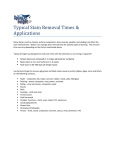
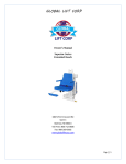
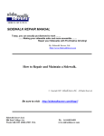
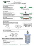
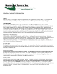
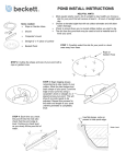
1
SUPERIOR SERIES SXR EXTENDED REACH TABLE OF CONTENTS 1. 2. 3. 4. 5. FEB 2012 New Construction Sleeve Anchor System Retro Fit Sleeve Anchor Method Fixed Anchor Optional Drop in Anchor Seat Installation Superior New Construction/Saw Cut Anchor SUPERIOR SERIES SXR EXTENDED REACH NEW CONSTRUCTION & SAW CUT SLEEVE ANCHORING METHOD INSTALLATION MANUAL FEB 2012 Superior New Construction/Saw Cut Anchor SUPERIOR SERIES SXR EXTENDED REACH SLEEVE ANCHORING SYSTEM INSTALLATION PARTS LIST FEB 2012 1 - Anchor Sleeve w/ Base 1 - Binding Screw 1 - Plastic Cap Superior New Construction/Saw Cut Anchor ANCHORING SLEEVE, BASE PLATE & BINDING SCREW SUPERIOR SXR EXTENDED REACH FEB 2012 Superior New Construction/Saw Cut Anchor ADA GUIDELINES FOR POOL LIFT PLACEMENT •Pool Lift Location. Pool lifts shall be located where the water level does not exceed 48 inches (1220 mm). Seat Location. In the raised position, the centerline of the seat shall be located over the deck and 16 inches (405 mm) minimum from the edge of the pool. The deck surface between the centerline of the seat and the pool edge shall have a slope not steeper than 1:48. •Clear Deck Space. On the side of the seat opposite the water, a clear deck space shall be provided parallel with the seat. The space shall be 36 inches (915 mm) wide minimum and shall extend forward 48 inches (1220 mm) minimum from a line located 12 inches (305 mm) behind the rear edge of the seat. The clear deck space shall have a slope not steeper than 1:48. •Submerged Depth. The lift shall be designed so that the seat will submerge to a water depth of 18 inches (455 mm) minimum below the stationary water level. FEB 2012 Superior New Construction/Saw Cut Anchor SUPERIOR SXR EXTENDED REACH – SLEEVE ANCHORING SYSTEM Water Pool Wall 12” to 24” Distance From Water’s Edge (front edge of anchor sleeve) Actual application Overview 4’ Anchor Sleeve Section Detail 4’ 4’ Cold Pin Concrete Anchor Sleeve 6” Cold Pin Concrete Binding screw COMPACT SAND Front of Anchor Sleeve must be 12” to 24” from the water’s edge Optimal placement is 12” to clear a spa bench Connect copper wire to the binding screw and then to your bonding grid Cold Pin’s should be ½” rebar 6” to 8” long Superior New Construction/Saw Cut NOTE: FEBMake 2012 sure your anchor sleeve is level and square with your pool’s edge. Anchor Step 1: Determine the location for installation (Make sure all ADA requirements are met). ***NOTE: The installation of Global Lift Corp’s anchor system’s are a guideline of minimum requirements. In some states or municipalities they may require additional steps due to their local codes or ordinances.*** Step 2: Make sure that all the parts are present (Refer to the parts list) 1 - Anchor Sleeve w/ Base 1 - Binding Screw 1 - Plastic Cap Step 3: At the determined location for installation, chalk out a 4’ X 4’ area prior to cutting out the concrete. (Refer to overview, the front end of the Anchor Sleeve must be 12” to 24” from the water’s edge and 6” deep). New Construction, the concrete must be 6” deep with a ½” reinforcing rod, minimum of an 18” grid. NOTE: Make sure that all local codes and ordinances are met. Step 4: Once the 4’ X 4’ area is cut out, make sure you drill in the inner wall of all 4 sides of the area (refer to the section detail) for the purpose of cold pinning the new concrete to the old concrete. Use 1/2” rebar, 6” to 8” in length. FEB 2012 Superior New Construction/Saw Cut Anchor Step 5: Place the Anchor Sleeve in the cut out area, make sure that the front of the Anchor Sleeve is 12” to 24” from the water’s edge. (refer to overview) A key element is to make sure that the Anchor Sleeve is level and square with the pool so that your Superior Series Lift sits properly on the deck. Step 6: Bonding the unit – The binding screw is supplied with the Anchor Sleeve locate the binding screw, connect the binding screw to the bonding grid. NOTE: Make sure that all local codes and ordinances are met. Step 7: Pouring your concrete, (make sure you cover the hole on your anchor sleeve with the plastic cap provided, so you don’t get concrete in the sleeve) a minimum of 4,000 psi concrete with reinforcing rod. Also make sure that the top of the anchor sleeve is flush with the deck. Before you install your lift make sure you let the concrete set up for 48 hours. Step 8: After the concrete has set for 48 hours, now it’s time to install your lift. Place your Superior Series Lift over the anchor sleeve, once you have completed the installation, please refer to User’s Manual for a safe operation. FEB 2012 Superior New Construction/Saw Cut Anchor SQUARE SLEEVE ANCHOR – PAVER INSTALLATION OPTION 1 4’ x 4’ Square 6” of Concrete SQUARE ANCHOR PAVERS PAVERS Please follow Square Anchor Instructions for Installation June 2013 SQUARE SLEEVE ANCHOR – PAVER INSTALLATION OPTION 2 4’ x 4’ Square 6” of Concrete SQUARE ANCHOR PAVERS PAVERS Option #2 same as Option 1, just recess the concrete down and reinstall the pavers over the concrete except directly under the pool lift, That section needs to remain concrete! Please follow Square Anchor Instructions for Installation June 2013 OVERVIEW SQUARE SLEEVE ANCHOR – Paver Option OPTION 1 SQUARE ANCHOR 4’ 4’ June 2013 OVERVIEW SQUARE SLEEVE ANCHOR – Paver Option OPTION 2 ANCHOR 4’ 4’ Option #2 same as Option 1, just recess the concrete down and reinstall the pavers over the concrete except directly under the lift, That section needs to be concrete June 2013 SUPERIOR SERIES SXR EXTENDED REACH RETRO-FIT SLEEVE ANCHORING METHOD INSTALLATION MANUAL RETRO-FIT SLEEVE ANCHORING SYSTEM SUPERIOR SERIES SXR EXTENDED REACH PACKING LIST • 1 – Anchor Sleeve w/ Base • 1 – Binding screw • 1 – Plastic Cap ADA GUIDELINES FOR POOL LIFT PLACEMENT •Pool Lift Location. Pool lifts shall be located where the water level does not exceed 48 inches (1220 mm). Seat Location. In the raised position, the centerline of the seat shall be located over the deck and 16 inches (405 mm) minimum from the edge of the pool. The deck surface between the centerline of the seat and the pool edge shall have a slope not steeper than 1:48. •Clear Deck Space. On the side of the seat opposite the water, a clear deck space shall be provided parallel with the seat. The space shall be 36 inches (915 mm) wide minimum and shall extend forward 48 inches (1220 mm) minimum from a line located 12 inches (305 mm) behind the rear edge of the seat. The clear deck space shall have a slope not steeper than 1:48. •Submerged Depth. The lift shall be designed so that the seat will submerge to a water depth of 18 inches (455 mm) minimum below the stationary water level. Water’s edge – Must be 12” to 24” in distance from the front of the anchor sleeve Front Edge of Anchor Sleeve Picture A Picture B STEP 1: Locate the retro-fit anchoring sleeve (as shown above) picture A • Once you determine where your lift is going to be located at your pool, place the anchor sleeve down So you can mark a circle around the base on the concrete where you will need to drill the hole. NOTE: From the water’s edge to the front end of the Anchor sleeve must 12” to 24”. See picture B ***NOTE: The installation of Global Lift Corp’s anchor system’s are a guideline of minimum requirements. In some states or municipalities they may require additional steps due to their local codes or ordinances.*** Front edge of anchor sleeve Measure Distance to make Sure It’s 12” to 24” to the water’s edge Picture A Picture B Step 2: You will need a 5” diameter core drilling bit. • Make sure you have accurately marked your hole location to be drilled. After drilling Your hole (picture A), it must be 6” deep and flat on the bottom of the hole (shown above). Also Double check your measurements, they should be: Place your anchor sleeve in the hole And make sure the front edge of the sleeve is 12” to 24” from the pools edge. Along with connecting the binding screw to the bonding grid and all local codes and ordinances are met. (picture B) STEP 3 : Cementing the anchor sleeve in the concrete. Make sure your anchor is level and Square. • You will need 10 lbs of Quick dry Anchoring Cement (Commercial Grade Quikrete Exterior Use Anchoring Cement) to complete the installation. You can purchase at any hardware store in your area. Read the label and follow manufacturer’s instructions. • Start pouring into the hole evenly until you fill it up, make sure not to overfill the Hole so that it does not create more work to scrap excess concrete off. • Let the concrete set for 24hrs, sand the area with a sand stone to smooth the finish. •Make sure the anchor sleeve is flush with the concrete. • You are now ready to install your Superior Series lift. Fixed Anchor Superior SXR Extended Reach Once you have completed the installation of your lift, locate the 3/8 bolt and secure it in the pre-drilled hole inside the anchor sleeve and tighten. Your lift is now ready to be used. Optional Fixed Drop In Anchor Instructions for Superior SXR Extended Reach Pre-drilled hole on the base of Superior Extended Reach After you have installed your square anchor, You are ready to install the optional fixed drop in anchor. Position the lift into square anchor. Locate the pre-drilled hole on the base of the lift. Now mark the concrete so you will know where to drill. Remove the lift from the anchor. You will need a 7/8” rock carbide drilling bit. • Make sure you have accurately marked the hole location to be drilled. After drilling your hole it must be 2 1/2” deep • Clean hole with pressurized air or vacuum. • Administer Epoxy into the hole prior to inserting the drop in anchor. • Drive the anchor flush with the surface of concrete . • Expand the anchor with the setting tool (provided). Anchor is properly expanded when shoulder of the setting tool is flush with the top of the anchor. • Position the lift back on the square anchor. • Insert drop in anchor bolt and tighten. • Fix your square anchor in place with the 3/8” bolt inside the anchor sleeve. Setting tool shown 3/8” bolt inside anchor sleeve GLOBAL LIFT CORP CUSTOM SEAT INSTALLATION MANUAL C, P & S Series Lifts GLOBAL LIFT CORP CUSTOM SEAT INSTALLATION MANUAL PARTS LIST 1 - Custom Seat 1 - Foot Rest 2 – Arm Rests 1 - Seat Belt & Buckle 1 – ½” x 2 3/4” Securing Bolt 3 – 5/16 x 3” Attaching Pin with lock nut 1 – 5/16 x 2” Foot Rest attaching bolt w/ nut 1 – 2” Round cap 1 – 1” Round cap INSTALLATION STEPS Picture A Step 1: Unpack your custom seat (picture A). Loose Items will consist of: • • • Foot Rest and Tube ½” x 3” Bolt w/ lock nut 5/16” x 2 ¾” Bolt with Lock nut INSTALLATION STEPS Picture A Picture B Step 2: Align your custom seat (Picture A), slide the lower seat tube into the upper Seat tube. Step 3: Once you have the seat in place, take your ½” x 3” bolt and slide it through the pre-drilled Holes (Picture B). Once you have inserted the bolt all the way through, apply the locking nut (supplied) and tighten down. INSTALLATION STEPS Step 4: Locate the 5/16 x 3” securing bolt (supplied), insert the bolt through the pre-drilled Seat and tube holes (As shown Above). Once you have the bolt inserted, secure the installation With the lock nut that is provided and tighten down. INSTALLATION STEPS FOOT REST Picture A Picture B Step 5: In picture A, slide the foot tube through the foot rest sleeve and line the hole to the Slot. In picture B, locate the 5/16” x 2” bolt and insert into the pre-drilled holes to secure the foot rest to the lift. Place the lock nut on the bolt and tighten down. Once that is complete, you are ready to enjoy your Global Lift Corp pool lift.