
1
$2.50 U.S.
$2.95 CANADA
JANUARY
1988
48784
THE MAGAZINE FOR THE ELECTRONICS ACTIVIST.
PROJECT PARADE
UNIVERSAL POWER SUPPLIES
One board, three configurations
TACHOMETER TESTER
Measure the true speed
SMT SPOTSCANNER
Hi -Tech darkroom meter
Listening Tube
MOSFET VOLTMETER
ap Checker
Unload your circuit problems
.5 -in. Disk Mod
and much, much more!
FOX-HOLE
RADIO
WWI crystal set
for today's DX
A
6ERNSBACK
T
0
896 48784
8
PUBLICATION
BUILD YOUR
WORKING
SELECT 5 BOOK S
Ow.
FIBEROPTIC
INFRARED
7111.11111r
BUILDER'S
h
R08DT
SONAN2
ROeDMS RO
for only $3. 95
AND LASER
SPACE -AGE
(values to $123.70)
and get a Free Gift!
PROTECTS
2800
,
$23.95
1529P
514.95
1111NNXrtl.r.
UP4XI.1.
VII
ELECTRONIC
1Y_=NQUPNQff4T
2724
$24.95
1663P
517.95
800P
S19. 95
METERS
SCOPES
IIO,A n1
USE
1'7 EQLIPNI.T
1625P
2758 524.95
514 95
TRANSMITTER
HUNTING
RADIO DIRLO LION
FINDING SIMPUIIID
110i
MASTER
S16.95
1492
514.95
BUILD
A
521.95
Electronics projects ... ideas ... the latest technology
all at up to 50% off publishers' prices
2825
2701P
517.95
Big Savings. In addition to this introductory
offer, you keep saving substantially with members' prices of up to 50% off the
Bonus Books. Starting immediately, you will be eligible for
publishers' prices.
Club
our Bonus Book Plan, with savings of up to 80% off publishers' prices.
News Bulletins. 14 times per year you will receive the Book Club News, describing all the current selections- mains, alternates, extras -plus bonus offers and
Automatic Order. If you
special sales, with hundreds of titles to choose from.
want the Main Selection, do nothing and it will be sent to you automatically. If
you prefer another selection, or no books at all, simply indicate your choice on
the reply form provided. As a member, you agree to purchase at least 3 books
Ironclad
within the next 12 months and may resign at any time thereafter.
No -Risk Guarantee. If not satisfied with your books, return them within 10 days
Exceptional Quality. All books are quality publishers'
without obligation!
editions especially selected by our Editorial Board.
1503P
FREE when you join!
Reference Guide to
Electronics Manufacturers'
PERSONAE
EARTR STATION
FOR WORLDWIDE
Reference Guide
lu Electronic.
Publications
SATELLITE TR
RECEPTION
time- and money- saving list
of product literature from all
A
\lanat'acturcr'
the major electronics suppliers.
l'uhlic:tliun
(a
MAW!
SOUND
RECORDING,
BUDGET
Counts as
516.95
515.95
NE NOR
ggappNC
EOM
LIn
p(OECIS
$6.95 value)
2635
1909P
527 95
Membership Benefits
COOROW
1199P
1999
519.95
2
ELECTRONJCS BOOK CHUE
DIGITAL
ELECTRONICS
,IWauuaLOeTNLc
FUNDAMENTALS
Blue Ridge Summit, PA 17294 -0810
TRANSDUCERS
Please accept my membership in the Electronics Book Club' and send the 5
volumes listed below, plus my FREE copy of Reference Guide to Electronics
Manufacturers' Publications (2683P), billing me $3.95 plus shipping and handling
charges. If not satisfied. may return the books within ten days without obligation
and have my membership canceled. agree to purchase at least 3 books at regular Club prices (plus shipping/handling) during the next 12 months, and may
resign any time thereafter.
I
I
2665
517.95
ewlNriL:l!sGlDr
1250P
1553
$14.95
S15.95
n1
TNF.
CiRRFTF 19E14
1
OSCILLOSCOPES
r"'^r
r
Name
Address
City
State /Zip
1693H
521.95
HC 'TROUBLESHOOT
ELECTRONIC
C RLPtl
CIRCUIT
rF'
I
Phone
Valid for new members only. Foreign applicants will receive special ordering instructions. Canada
must remit in U.S currenr.v This order subject to acceptance by the Electronics Book Club'
All books are hardcover unless numbers are followed by a
1536P
"P"
for paperback
58.95
CIRCLE 11 ON FREE INFORMATION CARD
RESP -188
1532P
514.95
1218P
514.95
KS
Volume 5, No.
1
January 1988
CONSTRUCTION
27
29
33
41
45
49
52
54
58
70
79
Build
a
Foxhole Radio-listen to modern radio on
a legend
One-Transistor VHF Signal Generator-pumps out harmonics up to 240 MHz
Build An SMT Darkroom Spotmeter- super-quality photographic prints
made easy
Night -Light Controller- automate your porch, driveway, or outdoor lights.
without RF interference
Build the MOSFET Voltmeter- measure voltage without skimping on the
readout or interrupting the test circuit's operation
Experimenter's Powered Solderless Bread /Clip Board -put schematic
diagram, notes, power supply, breadboard, and parts on one board.
Tachometer Tester-lets you gauge the accuracy of your tachometer
Universal Power Supply -the power -supply board whose output can be
tailored to fit the need
How Many Microfarads -how to figure out the value of unlabeled or
obscurely labeled capacitors
DX -COM -hear what you've been missing on the shortwave bands
Listen in on the Tube -combine eavesdropping and electronics
FEATURES
31
Scoping Out the Scope Market -how to select an oscilloscope
Hamfests, an Electronics Toyland -the place to get those much -needed
65
E -Z
24
parts or unload some old junk
Math-you can't design without it, but how can you avoid useless
theorems?
HANDS -ON REPORTS
39
43
Digital Voice Recorder -electronic memory stores your voice
Toshiba 3.5 -inch Floppy -Disk Drive Kit
3.5 -inch retrofit and a
screwdriver lets you read and write on 3.5 -inch disks
-a
SPECIAL COLUMNS
72
74
76
78
82
84
Friedman On Computers -you can't go home...it's just not in the program
Ellis On Antique Radio -taking a backward look
Carr On Ham Radio -how radio -wave progagation affects communications
Saxon On Scanners -the closest kept secret in scanner-ware
Jensen On DX'ing -the shortest distance between two points is not
necessarily a straight line
Circuit Circus-an electronics smorgasbord of circuits
DEPARTMENTS
2
4
14
16
37
63
Editorial -wait 'til next issue
New Products Showcase-fill your equipment shopping list
Letter Box -the place for electronics chit -chat
Bookshelf-take a look what's new in easy -to -read electronics books
FactCards -the desktop reference for component data applications
Free Information Card -reach out and touch the manufacturers
t
Volume 5, No. 1
January 1988
The Magazine for the Electronics Activist!
Larry Steckler, EHE, CET
Editor -In -Chief 8 Publisher
Art Kleiman, editorial director
Julian S. Martin, KA2GUN, editor
Robert A. Young, associate editor
Herb Friedman, W2ZLF, associate editor
John J. Yacono, associate editor
Brian C. Fenton, associate editor
Carl Laron, WB2SLR, associate editor
Byron G. Wels, K2AVB, associate editor
M. Harvey Gernsback, contributing editor
Teri Scaduto Wilson, editorial assistant
Ruby M. Yee, production director
Wait 'til next issue!
Who is the winning author of the Hands -on Electronics IBM
Clone Computer Contest?
Karen S. Tucker, production manager
Robert A. W. Lowndes, editorial
associate
Marcella Amoroso, production assistant
Jacqueline R Cheeseboro, circulation director
Arline R. Fishman, advertising director
you recall, back in April, 1987 we offered to present the author
of the best article published in that issue and all issues up to and
including the December 1987 issue of Hands-on Electronics a
computer as a bonus. Now (as write this editorial, the December, 1987 issue is being distributed to newsstands
throughout North America and many other outlets in the western
hemisphere, Asia, Europe, Australia, and Africa) you would
expect me to announce the winner- wrong!
If
I
BUSINESS AND EDITORIAL OFFICES
Gernsback Publications, Inc.
500-B Bi- County Boulevard
Farmingdale, NY 11735.
516/293 -3000
President: Larry Steckler
Vice -president: Cathy Steckler
recorded comments from our readers on the published articles
allowing you to become an active participant to the judging of the
winning article, and thus the winning author. Those comments
were screened for the first 30 days after each issue went on sale,
and the December 1987 issue was judged for the same period
and the contest closed. When you read this editorial, rest assured that the contest is closed (the December issue has been
on the newsstands for 30 days) and the winner is being selected.
I
NATIONAL ADVERTISING SALES
(For Advertising Inquiries Only)
Joe Shere MIDWEST /PACIFIC
1507 Bonnie Doone Terrace
Corona Del Mar. CA 92625
714/760-8697
The announcement of the contest winner will be made in the
February issue. That brings to a close the 1987 IBM -Clone
Computer Contest. So what do we do for 1988?
The Pattis Group
310 Madison Ave. Suite 1804
New York, NY 10017
212- 953-2121
like the contest idea, because the preceding contest brought
out the best in many first -time authors. So, I'm going to do it
again, beginning with this issue and all 1988 issues of Hands -on
Electronics. The February issue will give the details. may
change a rule or two including the prize.
I
Cover photography by
Herb Friedman
Design Color Labs
Composition by
Mates Graphics
.
I
To all my readers:
I
e)
wish for you a very happy, healthy, and
prosperous new year.
Mr
1
Hands-on Electronics. (ISSN 074329681 Published monthly by
Gernsback Publications. Inc 500.8 a-County Boulevard. Farm
ingdale. NV 11735 Second-Class postage paid Farmingdal,, N'
and at additional mailing 011iCes One-year twelve issues sue
bon rate U S and possessions S28 00. Canada $33 00.
untnes S35 50 Subscription orders payable in U S fund,
rnatonal Postal Money Order or check drawn on a U S barn
' single copy price S2 50 c 1987 by Gernsback Publications
All rights reserved Trademark registered m U S and Canada
led in U SA
a1
i
./master Please send address changes to Hands -On Elec.
PO Box 338. Mount Morris. IL
nnica. Subscription Dept
S4.9932
.
fmped self.addressed envelope must accompany all submined
'iuScripts and or artwork or photographs it Mee return is desired
,uld they be rejected We disclaim any responsibility for the losa
,i damage of manuscripts and or artwork or photographs while in
our possession or otherwise
Julian S. Martin, KA2GUN
Editor
As a service to readers. Hands-on Electronics publishes ava. ii
plans or information relating to newsworthy products. tech,
and scientific and technological developments Because of
variances in the quality and condition of materials and w. '.
,ship used by readers. Hands-on Electronics disclaims any
.ponsibility for the sate and proper functioning of reader bui,
,',ileCis based upon Or trOm plans or information published
;
,
ii"'
magazine
2
_
C
O
-
R
-_=_ - -
P
ass
__
R A
O
I
T
N
O
EAC, INC.
E. F.
J. W. MILLER AAVID ENGINE!
JOHNSON ATLANTIC SEMICONDUC'
LW
)
AK. Puerto Rico
'
'+`
INTEGRATED CIRCUITE
un
111
erDS
e000
SOLDER TAIL
01P SOCKETS
,.
.
w....
._...._.
DIAMOND TOOL UNGAR
AMDEK G.E.
«...._
011
«
...
..
"
T
T1
1
~ r,
1610.
.1
-
1
w.
^
...e
..
,
......e.
em
WIRE WRAP
DIP SOCKETS
--
-
o
40
3
4
MOO
.
:.
,---
a1
io
,
a
110
1.1
1a
.
.
ñ:l
22
woo
«
i0016eA011
MI.
m
1
1
.vv.y
14
1
11.1..41
116.
h
lee
..
<..
.. pu
.
A
2
T 00
162 60
110
SO
10
47 10
10
SO
Ó
612.
0710
SO
70210
I
i
11
r.wr.Nw
L*
mX..:..
DM KIT
bM
FBE
PANASONIC IN SI
:
1
ro
b
110
HO S
6r.
POS
sa
i'1C
CAT NO
,a12/
G/AGRg1t
1635
Twrv
+M
T
47
n
r. 4.. W.. ON.. Ow aft
01.rr...wr.nrewmr
.a.1...
i
i
OKAV
1700
1e
1
..
..
w
1
52
4 SO
56
4
21,10
17 SO
0
40 00
P
2000
10 00
!m
wm
á m0
sae
nm
1a
.
arm
..«me
SlnclnT..,1saH.rs
..
3
1...ew
d.
NI
le
1
°'_
.,«.'..r.
.F. .d1iu ..
-
u1
0r
3321 CO
7e1.0
MIMI
433:o
n
su
-
=NJ Senn d dine 1069
414 20
L..
r
mñ
.ySO
m
m1
v.s1.v
Ym
V
W
10
,or*
a*a
.
CO
467
01
r
¡.......e.-y......
r.
KO
0/
w
R,,,,I,I.
i.,,1
1
.61
r.
d
..m
xi
r1,.1
1.31
MO
iI,1 pM1.11
1
NV X
7.0
.
1..I...alac.
.
ss
0
t
OM
111101
A
1
eare.l...
8s1
2
ID
_iií.wu.e,sw
~
m6.
..,re
4
IS 1027
12
lt
.
,...e.
..+m A au
r
i
66
-
usa.+1a
v1
awúmlk
............................
...e
..Ir,rá.w
áw,
.0007. . móú6ú``
o
w.
T11
.
.11
.
.
.
w
..
au
V
íyi
....
.r ee
.
tm M w
w
arc
T
.
'
1
r4INI.w
.r««u. ^oa.w.<
.e
TM
oae
Reaitw
III./1,T
..
RIESLEPLESSEY
3CACH
CHEMICALS
51. Carbon Film
a.o`...
M_..'.,..
/
9103508982 DIGI KEY CORP
TWX
218 881 3380
Factory Firsts
'
'
FAX
82827914
DRAM 150NS $5.70'1; $39.951970DES
ES
CW INDUSTRIES
1)
X
Tle
218 881 8674
.`
256K (262,144
OKMACHINE MEWC INC ONTE SBÌLAD +
WU
/ 1- 800 -344 -4539
_
new
er en
,
XXI
CO
m
UlmlD ran
63+N
....e.r.um
404,
10
em
®
I
20
Aim
51
II
1
.
00 OM
r.
13
mw
..
uia
.
1
0 II IA
MS
If
MI
7
10
17
212
TO
A
IS
21
27
70
47
0
4 Se
LAS]
ISO
I.74
250
t7164
LAN
®
OE
1
into
ISO
100
0
IWO
17
MIS
MSS
11,
r.
.
n..
.a
W.
1
e.
,
1
1
..,
,
..
'
.
MA1wT Chips
u.........,
,.,.
.
,,
ó:.± :w
öó
11
.
.....n.
...
.
Mictlprocessor Chips
ma
i0w
°.......p
m
oon
..
E
.
1
IAA
...
o
--T-
100
ele
60
WA
SO
,. ...
.,,
1
.f:S,
0....... ti.
.
iv.,
......
....
.
..:
'_' E
,
.:._
a
t
a*I.
710
nm
m
1m
,.roareo.I
*..v
MHlunl.lnun,viri,.r.,...
1
..
ruc
.
211 611 46741
8T MAIL
SUM
YOUR
08085 TO
01411-1(11. P.O.
6w 677, WWI Eiwl
F.
...
en.
...
slae
8 ON
647111.
FREE INFORMATION CARD
1r
11
Is
r
1
>
'
wo
11
m.rm
1
MN
0 CO
MM
0
0.00_ 9.18
10.80$25.00
* 25.00-$48.18
i 50.00 *18.18
$
A
mn
Ca No
PCVDKn
aRB
6EE
.
ó
..T1
SERVICE CHARGES
$10008Up
CIRCLE
o
1
70
/111
77
2Q
61
3
1
S
NU
1
OD
w.
"
.ro
r.10
.p.
..1mu,u:oau
et.qi.Can.da.ldMe.ca
PNOBS. CALL 1.111111-344-41.11101K.Toll
.
mm
1*env
... .
rar..
e
1
I
ma
ma
1
1l
A.
óe..,,
n
.n
1ió
.
10
..
.
.1
TteOip-K..aNn.d.Own.m...a.dwO.A`noNm.mN.MO.I1m.a"°` Din 0.1n,..n.c°m".°krawlN.1.°e`e,n1 eons that ara not °.`eunm`°°"."'°°'In.,.N'.
ND blow+, tle P.n nn.w. ANer wre.p your order.101 Y al de decoantaW Heno and ePO 1M wow.. dem,nl To H. *dole
add v.
nema Then edd IM rwc
C1eP W. wo M anePU, a,m.su,.ae m amw.. n He U A. Canada and Meco we.n cr.ü or manes acaw ccarpenw Oc. Dy K. aces non duconlWe
ao,a. acan rllr..M can1.w11 U S. Ala.le
MKS 086168110 IT
0
a
...Ow.w 1.°.1w..,i:
e
SERIF S
w..
wr...lr.r.a..
e.s..re l0. m
m
t
,
New
,..,.
.. .r
1.-....twr:i.,:,.
Z.210
05J
o
,
m...,
KY,
lee
le
_4
6C,E{
m.Y.-...e.l...e.1o
a.te..OKr.
r+...4r0.Ir 100 ..aIr.
1a
1
I
13
.
.
40......
K.a
xu
V
..
M..I L..0 T.s..
0......
.
,
DO 41
4105
,.. ,...
r
SOW
K
PANASONIC
..M
a
.+.m.
34
12 (11
O
CAET
1
seua
s.
a..r*Xs
rum5*
261.0 1.1
*
NEC
a1
..
f
é.Pi ....
.
e
.
na
w o.
1..
,.
..
m.
vm10N
U.XIbt.100-{ rSGE.2RTtITL7S#:
n
"
:=
.
...
o0ö
N.
.. ,
.11140
MAI 500 7
-
::
CO
am
41 13
sp
m
ow
.
.
_
NEC
m
S.
®
1A.
Ñ1rN. *
1w_
.
b:
Add $2.00
Add 10.75
Add *0.50
Add wen
N,Charp.
1
.
1
A
16117
I
IMO
1
0
111111
MO
AM
20
.
D
.
2
a
C
VOLUME DISCOUNT
1
0.00-$ 99.99
8
100.00 $219.98
*
250.00-$N6.18
S
500 00.41069117
$1000 A Up
SIT
LAOS 1012
L0181fAL
Low a%
Lw1E%
D
Signal Processing Engine
a low cost ($9951. uxr- definable.
digital -signal processing board for use in
IBM, PC, XT, AT or a compatible computer? The R320 is a DSP engine utilizing
a 20MHz TMS32010 with 24K bytes of
dual -ported RAM, and direct I/O data
Need
transfer between the R320 and the PC.
located in the back, have been moved directly behind the front panel for easy access.
The P35 IC Model 2 will print at 300
cps in draft mode, and 250 cps in the
condensed printing mode, faster than the
original P35IC, while maintaining the
100-cps speed in letter-quality.
Increased software support now is
provided with 10 top packages, such as
Microsoft Chart, Computer Associates'
Supercalc 3A, Redding Groups' Graftalk,
Enertronics' Energraphics and a color
graphics driver for Lotus -2 -3.
1
CIRCLE 86 ON FREE INFORMATION CARD
It can perform spectrum analysis, digital filtering, signal averaging, speech processing, and telecommunications. Its
features include: extensive software support containing source code; PC /R320 upload/download routihes; executable files
in TURBO PASCAL & TM320I0 source
code; complete turnkey spectrum analysis
software; spectrum analysis via 1024
point FFT; data display for spectrum analyzer or digital scope; window generation
source code, comes with Harming; R320
accepts 8- or 12 -bit external data input;
optional turnkey 4 channel, 8 bit per channel, 500KHz per channel. 4- channel data
acquisition front end.
It's available from Rapid Systems Inc.,
433 N 34th Street, Seattle, WA 98103;
Tel. 206/547 -8311.
24-Pin Color Printer
a business or professional
printer user, who needs the advantages of
color text and graphics, as well as 24 -pin
letter quality and ease of use, Toshiba may
have your printer. They have designed and
augmented the front panel of a previous
model to incorporate user- friendly features.
An easy-to -use LED display has been
added to that the user can select, by sim-
If you're
ply touching a button, print quality, font,
pitch, paper motion, or quiet mode. The
printer is designed to allow users to significantly reduce the noise level, when
required, in an office environment.
The dip switches for the printer, usually
CIRCLE 66 ON FREE INFORMATION CARD
Purchasers of the P35IC Model 2 can
receive the Microsoft Chart free by returning a response card packaged with the
printer. Suggested retail price of the
P35IC Model 2, including the new features and all of the standard functions, is
$1749, the same as the previous model.
In addition to a bottom -feed provision.
especially useful for multipart forms,
other standard features are Qume Sprint
II, IBM Graphics Printer and IBM Color
Printer emulations; three resident type
fonts (prestige elite, courier, and highspeed draft) and the capability to accept a
wide variety of type fonts from optional
disks or cartridges.
Optional paper handling accessories
available include a dual -bin sheetfeeder,
unidirectional tractor and bidirectional
tractor. The P35 IC Model 2 is backed by
Toshiba's one -year warranty.
For further information contact Toshiba
America's Information Systems Division,
2441 Michelle Drive, Tustin, CA 92580,
Tel. 800/457 -7777.
TV Stereo -Signal Generator
To fill the service needs ut stereo television and VCR manufacturers. Leader
Instruments has a low cost/high performance MTS Signal Generator, Model
IN
.,
E
;
Us-
.
e e
°L
CIRCLE 52 ON FREE INFORMATION CARD
LMS -237. The versatile generator
provides the necessary signals for test and
alignment of both stereo and SAP (Secondary Audio Program) decoders.
On -screen character displays (L, L, R,
and L-R) indicate the selected mode of
stereo or mono operation. Composite stereo and SAP outputs at baseband, SIF
(4.5 MHz), VIF (45.75 MHz), Channel 3,
and Channel 4 allow the technician to
pinpoint the area of malfunction. Four
selectable, internal- modulation frequencies (300 Hz, I kHz, 3 kHz, 8 kHz) at 14%
modulation ( -17 dB), as required by the
manufacturers, are provided.
For more information on the LMS -238,
which retails for $600. contact Leader
Instruments Corporation, 380 Oser Ave-
nue. Hauppauge, NY 11788, Tel.
516/231 -6900. or 800/654 -5104.
Self- Feeding Solder Gun
How would you like a self-feeding, solid -state electric solder gun with replaceable snap -in solder cartridges? Extremely
light in weight but rugged in construction,
this line of solder guns uses a patented
self-feeding system whereby the solder is
fed from the solder cartridge to the solder
tip.
SOLDER
FEEDS
ITSELF
TRIGGER
RELEASE
CIRCLE 63 ON FREE INFORMATION CARD
Just squeezing the trigger in the handle
of the gun. advances the solder automat-
0o
YOU
REALLY
BET THE BEBT BUY
FROM
et 's face it: There will always be some outfit
that can undercut a published price. They
do it by having no overhead. and no
responsibility to you, the consumer.
"So, you want that Jerrold 450
combo? The one that POCMCCII O
CO.. INC.. is offering for $199°Ó?
Well, that's a good price, but
here's what I'll do..." What may
happen is that you may save a
couple of bucks at the time. But suppose
there's a problem (and it happens to the best
of them,) and you call that "Dealer "... This could be what you'll hear:
"No, Steve isn't here. He moved out, the bum! And he owes me 543700 on the phone bill, No, don't
know about any guarantees on your Gerald, who's that'? Listen, if you see that creep..." etc.
At hc1nCc IISCO., you've got an established company who will be here for you, time after time We may be tough competitors, but we've
got a soft spot for our clients! Try us, and be treated right -and we'll prove it by giving a one -year warranty on everything we sell.
Check our prices on scientific Atlanta Units!
I
Io on
MORE
ITEM
UNIT
RCA 36 Channel Converter ICh.3 output only)
Panasonic Wireless Converter (our best buy)
400 or 450 Converter (manual hne tune)
Jerrold 400 Combo
Jerrold 400 Hand Remote Control
Jerrold 450 Combo
Jerrold 450 Hand Remote Control
Jerrold SB- Add On
Jerrold SB-Add -On with Tnmode
M -35 B Combo and
M -35 B Combo unit
(Ch 3 output only)
with VanSync
CHECK US OUT -WE'LL
MEET OR BEAT THE OTHER'S
ADVERTISED WHOLESALE
1
ITEM
UNIT
2900
8800
8800
69.00
16900
119.00
2900
1800
Econocode with VanSync
19900
t3900
2900
8900
9900
9900
18.00
MLD- 1200 -3 (Ch 3 output)
MLD 1200- 21Ch.2 output)
8900
9900
t45 00
7900
8900
9910
9900
Zendh
17500
10900
7500
1800
6900
5800
7000
7000
Quantity
Mimcode IN -12)
Muncode IN -12) with Van Sync
Mmicode VanSync with Auto On -Oft
Econocode lmmicode substitute)
-
SSAVI Cable Ready
Interference Filters (Ch .3 only)
Eagle PD -3 Descrambler(Ch 3 output only)
'Scientific Atlanta Add -on Replacement Descrambler
Output
Channel
Item
Price
Each
IO OR
MORE
5800
62 00
10500
5200
5600
58.00
58.00
2400
12500
t4 00
11900
6500
t1900
75.00
TOTAL
PRICE
OR RETAIL PRICES!
VISA
SUBTOTAL
Californ a Penal Code 8593 -D forbids us from
shipping any cable descrambling unit to anyone
residing in the state of California.
Prices subject to change without notice
Pacific Cable Co., Inc.
PLEASE PRINT
73251/2 Reseda Blvd., Dept.
Name
H -1
Reseda, CA 91335
(818) 716 -5914 (818) 716 -5140
NO COLLECT CALLS!
IMPORTANT When ordering, please have
the make and model number of the equipment
used in your area -Thank you!
°Call for availability
Prices subject to change without notice
Jerrold u
a
registered trademark of General Instruments Corp
$3 00 per unit
COD 8 Credo
Cards -Add 5%
TOTAL
Address
State
Shipping Add
City
Zip
D Cashier's Check
Phone Number l
Money Order
Acct.*
)
D C.O.D
D Visa
Mastercard
Exp Date
Signature
-
FOR OUR RECORDS
DECLARATION OF AUTHORIZED USE
I. the undersigned, do hereby declare
under penalty of penury
that all products purchased, now and in the future, will only be used on cable TV systems with proper
authorization from local officials or cable company officials in accordance with all applicable federal and
state laws.
Dated
Signed
5
e
ically onto the hot tip, thereby allowing
the user to flow the solder exactly where
needed! That method makes soldering so
easy that you can do it with one hand tied
behind your back.
The one -handed Soldereaze Solder
Gun comes in eight different models from
25 to 150 watt, and features models with
an adjustable tip -temperature control, as
well as two models with the added feature
of a digital temperature read -out. Retail
prices range from $21.00 to $66.00. Further details and full -color literature are
available from: Soldermatic Corp., 3607
Howard Street, Skokie, IL. 60076; Tel.
312/673 -1111
IDC- Assembly Press
The IDC Bench Assembly Press is per-
fect for short -run production, R &D
Centers, MRO's, and service technicians.
The IDC Bench Assembly Press is capable of low- volume mass termination of
various IDC connectors on flat (ribbon)
back that cause our rigs to quit working on
certain bands; excessive RF coupling to
AC lines that causes everything to quit
working; our neighbors screaming about
TVI and RFI; our computers computing
gibberish; or we simply can't talk across
town because of extreme ground losses or
radiation pattern distortion.
Let the new MFJ -931 create an artificial
RF ground with a random length of wire
thrown along the floor. It's very effective
at placing your rig at or near actual -earth
ground potential even if your rig is on a
second or higher floor.
That's not all -the MFJ -931 can also
electrically place a far-away ground directly at your rig, no matter how far away
it is. It tunes out the reactance of the wire
that connects your existing ground to your
rig.
CIRCLE 84 ON FREE INFORMATION CARD
Convenient, quick, and easy to use, the
manual press has interchangeable
base plates (no tools required) and accommodates a broad range of IDC's including
female socket transition connectors, card edge connectors, standard DIP plugs, and
D -subs. The interchangeable base plate
terminates up to 64 -pin IDCs. Cartridge
style allows for quick change with virtually no set up.
The IDC Bench Assembly Press has a
suggested retail price of $139.95 (base
plates and cutters are sold separately) and
is available at electronic equipment suppliers nationwide.
For more information on the IDC
Bench Assembly Press contact PanaVise
Products, Inc., 2850 E. 29th St., Long
Beach, CA 90806; Tel. 213/595 -7621.
1/4-ton
Artificial RF Ground
Don't we all sometimes have problems
with not having a good RF ground? Problems like RF "hot spots" that "bite" our
lips or fingers when we transmit; RF feed-
configured
as
either input or output.
What's more, port C may also be divided
into two 4 -bit ports that may be set as
inputs or outputs independently.
CIRCLE 60 ON FREE INFORMATION CARD
cable.
CIRCLE 93 ON FREE INFORMATION CARD
Digital I/O Board
MetraByte's P10 -24 is a high -current,
parallel I/O card which allows 24 TTL/
DTL compatible digital I/O lines to be
monitored or controlled by a Personal
Computer. The 24 I/O lines are divided
into three 8- Bit ports. Each port may be
The MFJ -931 connects between the
ground connection of your transmitter or
antenna tunner and a random length of
wire thrown along the floor. Two knobs on
the MFJ-93I are adjusted for maximum
RF-ground current using its built -in RF
ammeter. That resonates the random wire,
converts it into a tuned counterpoise, and
presents an effective low impedance near
ground potential to your rig, thus creating
an artificial RF ground.
To electrically place a far-away ground
directly at your radio equipment, simply
connect the MFJ -931 between your rig
and connecting ground wire and adjust its
two knobs for maximum RF current using
its RF ammeter. That tunes out the reactance of the connecting wire, reduces the
electrical ground lead length to virtually
zero, and electrically places your far-away
ground directly at your rig.
The MFJ-931 covers 1.8 to 30 MHz and
has a built -in RF ammeter for indicating
RF- ground current. It's ruggedly built in
an all aluminum cabinet with a brushed aluminum front panel.
The MFJ -931 retails for $79.95 it
comes with a one -year unconditional
guarantee and if ordered directly from
MFJ Enterprises, Inc. it can be returned
within 30 days for a full refund (less shipping and handling) if not satisfied.
For additional information contact MFJ
Enterprises, Inc. at P.O. Box 494, Mis-
sissippi State, MS 39762; Tel.
800/647 -1800 or 601/323 -5869.
Typical applications for the P10 -24 include contact -closure monitoring, digital
I/O control, interface to PB -16A, and similar Solid -State I/O module racks, plotter
interfaces, and a wide variety of other
digital- interface tasks.
Programming the P10 -24 is extremely
simple. The board uses four addresses in
the PC's I/O address space. Those addresses represent one control word which
simply tells the board which ports are to
be inputs, and which will be outputs. The
remaining three ports directly write to or
read from the three 8 -bit I/O ports.
Power from the PC -bus is brought out
through the P10 -24 connector, allowing
external circuitry to be developed without
the need for external power supplies. The
P10 -24 allows full access to the PC's interrupt- control lines, which allows the
board to be used in a wide variety of highspeed I/O interface applications.
The P10 -24 sells for $165.00. For further information contact MetraByte, 440
Myles Standish Blvd., Taunton, MA
02780.
,..
"Junior spoke his first words today!
"Woofer' and Tweeter'!"
9
BUILD -IT BOOKS
FOR EXPERIMENTERS
80386 Personal Computer
Designated as the MP 386 Series, these
industry- standard personal computers are
multifaceted enough to be used as high performance personal workstations, as
the hub of a departmental local area network, or as the main component in a
multi -user Xenix or Unix installation.
The MP 386 is based on Intel's 80386
u
CIRCLE 57 ON FREE INFORMATION CARD
The MP 386 is available in multiple system configurations including one flop-
drive, one floppy disk
drive /4OMB, one floppy disk
py disk
drive /70MB, and one floppy disk
drive /120MB. Each configuration is available separately or bundled with one of the
following display monitors: EGA, auto tracking Diamond Scan, or monochrome.
Extensive software and hardware enhancements also available with the MP
386, such as 5 -1/4" I.2MB or 360KB, and
3 -1/2" 720KB floppy disk drives; 40MB,
70MB, and 120MB fixed disk drives;
4MB expansion memory board; Intelligent Multi -Port Board (8- channels); and
floor stand.
The MP 386 comes with a one -year
warranty backed by a national network of
service centers and regional Mitsubishi
repair depots. Established pricing for the
40MB configuration is $5,995.00.
For additional information on any of
the Mitsubishi brand -name personal computers, contact Mitsubishi Electronics
America, Inc., 991 Knox Street, Torrance. CA 90502; Tel. 213/515 -3993.
Emergency Radio Systems
Midland Model 77 -91IC includes
an
ultra -compact 40-channel Ready Rescue
AMP
OP-
PROJECTS....
55.00. Wide range of build
-
projects that use op-
it
amps. Easy to build board
layouts provided for most A
variety of projects of all
kinds are included
kve
microprocessor that operates at
I6MHz/Owait. Standard features include
32KB of cache memory. expandable to
64KB, sockets for 80287 or 80387 numeric coprocessor, 10 slots for expansion and
custom configuring, and 5 half-height,
mass -storage devices, providing user flexibility. Also, the MP 386 runs virtually
every MS -DOS compatible program, as
well as supporting most Xenix -based software programs.
BP106- MODERN
Modern Op Amp
Protect.
eOPl.ota
11.11.e1C
#223- PROJECTS
H
w130
USING THE CA3130....
$5.00. 50 different ways to
put this op -amp to work in-
cluding audio.
RF.
test
llr
equipment. household and
miscellaneous projects.
CIRCLE 70 ON FREE INFORMATION CARD
transceiver with '/x" high LED channel
readout. emergency button for instant
channel 9, electronic channel tuning with
up /down switches. LED bar lights for
"S" and "RF" readings, computer circuitry, and volume and squelch controls.
The package also includes a unique
slide -on battery pack for emergency backup power or portable use, a cigarette lighter adapter for mobile use, a telescoping magnetic antenna. and a vinyl carrying case. Suggest retail price is $129.95.
Model 77 -915C offers a 4 -watt mobile
transceiver with instant access to emergency channel 9 or highway assistance
channel 19, ANL, TX. and RX indicators, and modern slide control knobs for
volume and squelch. A pre-tuned telescopic antenna with magnetic mount, cigarette lighter power cord, and vinyl
carrying case complete the package. Suggested retail price is $79.95.
For more information about Midland's
new emergency radio systems, contact
Midland International, Consumer Products Division, 1690 N. Topping, Kansas
City, MO 64120.
11
VGA Upgrade Chip
This unit is an inexpensive ROM BIOS
replacement that gives users a convenient
upgrade to the new IBM 640 x 480, land I6 -color VGA video standard with
the EGA Multi Res adapter.
When installed on the EGA Multi Res
video adapter, the BIOS chip provides
support for VGA 640 -by -480, 2 and 16
color modes on multifrequency monitors.
Because VGA compatibility is maintained through hardware support at the
BIOS level, no preboot software or unique
drivers are required.
By adding VGA capabilities to existing
features, the BIOS upgrade protects the
investment of EGA Multi Res users. Current EGA Multi Res adapters can be enhanced with the upgrade, and new
shipments will include the new ROM
BIOS as a standard feature.
In addition to VGA support, the EGA
Multi RES provides a variety of high -resolution 16 color modes on a large selection
IC
NIA P.a«.+a
4
BP44 -IC 555 PROJECTS
$5.95. Included
are basic and general timer
....
circuits. automobile and
model railroad circuits
.
alarms and noise makers.
as well as a section on 556.
558. and 559 timers
SOCMOe M
Pro)rot.
I
#224 -50 CMOS IC".
PROJECTS
....
$5.25.
These ICs are suitable for
an extraordinary range of
applications This book
shows you just how much
you can do with them.
Suomi Deak of
BP59-2ND BOOK OF
CMOS IC
PROJECTS....
55.00. Still more ways to
use these versatile devices
None of these projects overlap those in book #224
The pair make a wonderful
circuit reference set.
131284-DIGITAL IC 61.
PROJECTS
NOW IC
P.ol.ct.
.... $5.25.
Both simple and more advanced projects to help the
reader develop a knowledge of the workings of dig
tal circuits. A number of
board layouts are included
MAIL TO.
PO. Box
Technology Today Inc.
240
Massapequa Park. NY 11762 -0240
SHIPPING CHARGES
$0.01 to $5.00....$1.00
$5.01 to $10.00 ..$1.75
$10.01 to 20.00...$2.75
$20.01 to
IN USA & CANADA
$30.01 to 40.00...$4.75
$40.01 to 50.00...$5.75
$50.01 and above $7.00
30.00...$3.75
OUTSIDE USA & CANADA
Multiply Shipping by 2 for sea mall
Multiply Shipping by 4 for air mail
Total price of merchandise
$
Shipping (see chart)
S
Subtotal
S
Sales Tax (NYS only)
S
Total Enclosed
S
Name
Address
City
L
State
Zip
7
CABLE-TV
f-
Or /Pr r
.
fflii./..,-
.....
..
J, ,
%CAI
signal
-
A
....._..
IA
remover
SOde NOTCH FILTER
Any* signal coming in on your cable can be completely
"removed" with this powerful filter. Particularly useful
on "pay" chaenets. Also can be used to eliminate any
over- the -air sigaal which precepts normal reception. The
filter's catiraal adiustmeets allow precise tuning to ley
frequency required.
'AVAILABLE FOR THE FOLLOWING CHANNELS:
MODEL 26
-
For any channel between 2 and 6
(Tuning range 54 - 108 Mhz)
MODEL 713 - For any channel between 7 and 13
(Tuning range 174 - 216 Mhz)
MODEL 1422 -For any channel between 14(A) and 22(1)
(Tuning range 120 - 174 Mhz)
**
**
**
30 DAY FREE TRIAL
ONLY $30 EACH
To order, send $30 check or money order. Specify
Model. If not compietely satisfied,simply return within
30 days tor a full and speedy refund.
One year warranty
All models in stock
*Quantity discounts to 50%
Fast, free delivery
*
*
*
STAR CIRCUITS /DEPT.
H
P.O. BOX 8332, PEMBROKE PINES, FL 33084
CIRCLE 72 ON FREE INFORMATION CARD
audio levels directly in either dB or Watts.
Sencore's SR68 allows technicians to
automatically measure audio separation
of stereo circuits to as low as -40dB, without having to refer to calculations, by simply turning one knob. The unit gives the
user the convenience of a portable by operating 50 hours on one charge, and utilizes an auto -off feature to help conserve
batteries for long life.
The SR68 sells for $595. and is supplied with a PA235 power adapter. Optional accessories include a BY234 lead -
of monitors. The adapter displays EGA
acid battery for portable operation
software in 640 -by-350 on multifrequency, EGA and 25Khz monitors.
The board also produces a superior
832 -by -350 resolution on EGA monitors.
On multifrequency monitors, the adapter
($59.95), and
generates higher resolutions of 640 by-480 and 752 -by -410. in addition to the
new VGA modes. The EGA Multi Res is
fully compatible with the IBM PC, XT,
AT and equivalent systems.
The BIOS upgrade for the EGA Multi
Res is available for only $25.00 from
STB. Customers wanting to order the chip
should write to STB Systems, Inc., ATT:
Customer Support, 1651 North Glenville,
Suite 210, Richardson, Texas 75081. Or
customers can call STB's Customer Support at 214/234 -8750.
The EGA Multi Res adapter, which
now includes the new BIOS, sells competitively for $399.00 (US suggested resale). The adapter is available through
STB dealers and distributors.
For more information about the EGA
Multi Res contact STB at 1651 North
Glenville. Suite 210, Richardson, Texas
a PC253 protective cover/
lead storage ($49.95). Contact Sencore
Inc.. 3200 Sencore Dr., Sioux Falls, SD
57107; Tel. 800/843 -3338.
Multisync Color- Graphics Board
The MultiSync Color- Graphics Board
Model GB -I. is an ultra high resolution
(640x480), 16 -color display card (from a
palette of 64 colors) for use with an NEC
MultiSync Color Monitor or its functional
equivalent.
The MultiSync Color-Graphics Board
resolution sets a new graphics standard
beyond EGA (Enhanced Graphics Adapter) when displayed on an NEC MultiSync
Monitor. That resolution matches the
IBM Professional Graphics Controller
(PGC or PGA -Professional Graphics
Adapter) in resolution but at an EGA
price. The suggested retail price for the
model GB -1 is $549.00.
75081; Tel. 214/234-8750.
Stereo -TV Readout
The SR68 Stereo -TV Readout allows
the service technician to measure the output of audio amplifiers, either at the line
or speaker outputs. The SR68 incorporates dummy loads that provide up to 100watts -per channel of power dissipation to
catch even elusive problems that may
show only when components are stressed
at their full potential. The SR68 Stereo TV Readout provides dual meters to visually monitor the outputs, and measure the
CIRCLE 78 ON FREE INFORMATION CARD
8
CIRCLE
6 ON
FREE INFORMATION CARD
CIRCLE 89 ON FREE INFORMATION CARD
Compatibility for running software in
CGA (Color Graphics Adapter), EGA.
MDA (Monochrome Display Adapter)
and Hercules modes is made possible
through the MultiSync Color- Graphics
Board's hardware trapping which is faster
than software trapping and supports all
functions of true EGA. Users with extensive software libraries won't have to update their software in order to benefit from
GB -l's many features.
The Extended text modes enable users
to display a full page of text (80 characters
by 60 lines) or spreadsheets with up to 132
columns by 44 lines providing a wide
range of terminal emulation capabilities.
The MultiSync Color-Graphics Board
also provides screen drivers to allow users
(Continued on page 12)
Train for the Fastest Growing Job Skill in America
Only 1VRI teaches you to service all corn uters
as you build your own fully IBMcornpatible micro computer
With computers firmly established in
offices -and more and more new
applications being developed for every
facet of business -the demand for
trained computer service technicians
surges forward. The Department of
Labor estimates that computer
service jobs will actually double in the
next ten years
faster growth rate
than for any other occupation.
-a
Total systems training
No computer stands alone..
it's part of a total system. And
if you want to learn to service and
repair computers, you have to understand computer systems. Only NRI
includes a powerful computer system
as part of your training, centered
around the new, fully IBM -compatible
Sanyo 880 Series computer.
As part of your training, you'll
build this highly rated, 16-bit IBM compatible computer system. You'll
assemble Sanyo's "intelligent" keyboard, install the power supply and
disk drive and interface the high resolution monitor. The 880 Computer
has two operating speeds: Standard
IBM speed of 4.77 MHz and a
remarkable turbo speed of 8 MHz.
It's confidence-building, real -world
experience that includes training in
programming, circuit design and
peripheral maintenance.
No experience necessary
NRI builds it in
-
Even if you've never had any previous
training in electronics, you can succeed
with NRI training. You'll start with
the basics, then rapidly build on them
to master such concepts as digital
logic, microprocessor design, and
computer memory. You'll build and
test advanced electronic circuits using
the exclusive NRI Discovery Lab ®,
professional digital multimeter, and
logic probe. Like your computer,
they're all yours to keep as part of
your training. You even get some
Your NRI total
systems training includes all of this'
NRI Discovery Lab to design and modify circuits
Fourf unction digital multimeter with walk-you-through instruction on
audio taps Digital logic probe for visual examination of computer circuits
Sanyo 830 Series Computer with "intelligent" keyboard and 360K
double- density, double-sided disk drive High resolution monochrome
monitor 8K ROM. 256K RAM Bundled software including GW
BASIC. MS DOS. WordStar, CalcStar Reference manuals, schematic
and bite-sized lessons.
of the most popular
software, including
WordStar, CalcStar,
GW Basic and MS
DOS.
NRI is the only technical
school that trains you as
you ass amble a top -brand
microcomputer. After
building your own logic
probe, you'll assemble the
"intelligent" keyboard..
Send for 100-page
free catalog
Send the post -paid
reply card today for
NRI's 100 -page, full-color catalog,
with all the facts about at -home
computer training. Read detailed
descriptions of each lesson, each
experiment you perform. See each
piece of hands -on equipment you'll
work with and keep. And check
out NRI training in other high -tech
fields such as Robotics, Data Communications, TV /Audio/Video
Servicing, and more.
If the card has been used, write to
NRI Schools, 3939 Wisconsin Ave.,
N.W, Washington, D.C. 20016.
then install
the computer
power supply,
checking all
the circuits
and connections with
NRI's Digital
Multimeter.
From there,
you'll move on
to install the
disk drive and
monitor.
ArAP,SCHOOL S
McGraw-Hill Continuing Education Center
3939 Wisconsin Avenue, NW
Washington, DC 20016
e-1 ir"
We'll Give You Tomorrow.
I' rIli
IBM is a Registered Trademark of Irnemational Business
Machine Corporation.
11
(Continued from page 8/
patible computers. Turnkey software allows you to install it and get it running in 2
minutes.
of Lotus -2 -3, Media Cybernetics' Dr.
Halo. and AutoDesk's AUTOCAD to take
full advantage of 640 x 480 resolution
medical, Speech Analysis, Chemical,
NEW PRODUCTS SHOWCASE
Applications: Electronics, Bio-
1
mode and Miscrosoft Windows. In addition, NEC has a growing list of software
developers who are committed to supporting the GB -l's extended modes.
Incorporated into the MultiSync ColorGraphics Board are several other special
features, including: Parallel Printer Port,
which supports the 1/O port of the LPTI or
LPT2 to open up a slot on the user's PC; a
free Printer Spooler utility for higher user
productivity, and Hardware Zoom and
Viewport, to allow users to zoom in up to
eight times closer to magnify screens for
detailed viewing or pixel editing. There is
a potential 300% speed improvement by
using an ET2000 chip set with a microengine to assume certain CPU functions.
such as memory write /read tasks associated with bit -mapped graphics displays.
For further information contact NEC
Home Electronics Inc.. 1255 Michael
Drive, Wood Dale, IL 60191: Tel.
312/860-9500 ext. 4244.
Portable PC
The T1000 features an 80088 microprocessor running at 4.77 megahertz,
with a single 720- kilobyte 3.5 -inch diskette drive.
Measuring 12.2 inches wide by 2.05
inches high by II inches deep, the fully
portable PC has a built-in handle and rechargeable NiCad battery for up to five
hours of cordless computer use.
The unit's 110 VAC power adapter can
be used for recharging or line operation.
An optional automobile power adapter
gives additional power on- the -road.
Equipped with 5I2KB of random -access memory, the system can be enhanced
with an optional 768KB memory card for
an additional I28KB user -RAM and
640KB Lotus /Intel /Microsoft expanded
memory specification.
Operating with MS -DOS 2.11 in read only memory, the T1000 is designed for
efficient use of a single drive system. Automatic "hooting up" from ROM leaves
CIRCLE
81 ON
FREE INFORMATION CARD
the diskette drive free for loading application programs.
Full system capabilities are provided by
the TI000's six standard ports: parallel
printer. RS -232C serial. RGB color video, composite video, external 5.25 -inch
diskette drive and external numeric keypad.
A real -time clock/calendar and space
for Toshiba's optional 300/1200 bits -persecond Hayes- compatible modem are also
built in.
Documentation includes a user manual
and MS -DOS quick -reference card. A
complete MS -DOS 2.11 manual is available, as well as MS -DOS 3.2 on 3.5 -inch
diskette and manual.
Toshiba's optional 5.25 -inch external
diskette drive or Floppy Link, a device
that connects a desktop PC's drive to the
T1000, provides a mode of transferring
data to and from 5.25 -inch diskettes.
Toshiba's one -year parts and labor warranty, including free enrollment in the
"Exceptional Care" replacement program. supports the new T1000. The unit is
priced at $1199. For more information
contact Toshiba America, Inc., Informa-
Automotive, Power, and Data Acquisition. Features include: 2-channel simultaneous acquisition, 20-MHz sampling rate
per channel, deep 64K byte buffers per
channel, 8 bits of accuracy, switch selectable I- Megohm or 50 -ohm BNC input
with warning light, programmable gain
from 10 mV /division to 50 V /division,
programmable sample rate from I Hz to
20 MHz in 1/2/5 sequence, pre- and posttriggering capabilities, digital or analog,
internal or external trigger, AC or DC
coupling, automatic channel calibration,
menu -driven operation, cursor with time/
voltage readout, screen dumps to printer,
save /retrieve to /from disk, options include: real -time spectrum analysis using
FFT 128K-byte buffers per channel
The price of the R2000 is $3495, and it
is available from Rapid Systems Inc., 433
N 34th Street. Seattle, WA 98103: Tel.
206/547-8311.
Liquid Electrical Tape
The product is a liquid vinyl, which is
applied to wire or terminal junctions to
seal out moisture and prevent corrosion.
The coating also helps hold wires and
terminals together so that vibration does
not result in a loose connection.
Starbrite Liquid Electrical Tape is extremely easy to use -apply with the applicator brush/cap and let dry. Unlike
conventional electrical tape. the protected
connection is neat, clean, and totally waterproof.
tion Systems Division, 9740 Irvine
Blvd., Irvine, CA. 92718; Tel.
800/457 -7777.
PC -Based Storage Oscilloscope
Here's a 2- channel 20 MHz digital storage oscilloscope that uses the PC for
display and storage -the first technically
advanced, full featured PC -based scope
for less than $3500. A unique combination of high speed, large memory, programmable gain and 2 simultaneous
channels utilizing the power of the PC.
Works with IBM PC, XT, AT and com-
Star brae
ELECTRICAL
With
TAPE
AppBCata
Brush Call
FLAkt u
DANGERI
CIRCLE 55 ON FREE INFORMATION CARD
"
;
(.0
'
Ft. Lauderdale, FL. 33314: Tel.
"I just found out...
we are
12
industrial workaholics!"
Starbrite Liquid Electrical Tape is
available in 4 fl. oz. for $4.95 and 32 fl.
oz. for $24.95, and it comes in black, red,
green, and white. Larger size containers
are available for large-scale industrial use.
For further information contact Starbrite, 3650 Hacienda Blvd., Building F.,
CIRCLE 68 ON FREE INFORMATION CARD
800/327 -8583 (in Florida 305/587- 6280).
Satellite Locator
A slide rule that gives azimuth /elevation angles to geosynchronous satellites
from almost anywhere on Earth is available from WTS Products.
On that one slide rule is included: a
visual representation of the full satellite
arc, horizon -to- horizon, around the
world, even from the southern hemisphere, with local azimuth and elevation
angles, U.S. satellite longitude positions,
a magnetic declination map of the U.S., a
true -to- magnetic azimuth conversion
slide rule, and handy formulas for greater
precision.
...
..
t-t
;''i
..
-
-
r};
a
7/.24",`,.;
y
fzrc^ti:t1
ifltt't3Fi
,
111«X1
=
CIRCLE 88 ON FREE INFORMATION CARD
The device allows the quick determination of az/el angles from anywhere on
Earth that the satellite arc is visible. A
magnetic declination map and a true /magnetic slide rule on the back allows the true
azimuth to be converted to local magnetic
azimuth. The az/el formulas are also
printed on the back to allow more precise
angle computation with a portable calculator.
The price is $10 each (shipping included). For more information write to
WTS Products, 4308 South Peoria, Suite
681, Tulsa, OK 74105.
Logic Analyzer
The 16 -bit Logic Analyzer kit can be
used to troubleshoot or verify the proper
operation of circuits that contain sequen-
tial and/or combination logic. Included
with the Analyzer is special software
making it fully keyboard -configurable
and menu -driven.
The Logic Analyzer has 16 data lines.
There is also a clock input and two clock qualifier inputs. The analyzer is compatible with TTL and 5 -volt CMOS logic.
With the accompanying software, the
Logic Analyzer enables a computer to
show state and timing displays including
hex/octal and ASCII equivalents, an address relative to triggering, and other information. That data can then be saved on
disk for later examination or comparison.
Other operations include a checksum capability with bit selection for easy com-
serial connector for linking up to a computer or terminal and features automatic
baud -rate selection between 300 and
I9.2K baud. There are also oscilloscope
trigger outputs for use with a scope. The
IC -1001 has high -impedance inputs for
minimum circuit loading while all inputs
attach to circuits by convenient spring loaded clips. The retail price of the Heath kit IC -1001 is $269.00. For further information about the Heathkit IC -1001 Logic
Analyzer contact Heath Company. Department 150 -935, St. Joseph. MI 49022.
'44.11111MNIONIRIMM
CIRCLE
91
ON FREE INFORMATION CARD
parison of acquired data, and the ability to
search the data for a specific bit pattern.
On-screen help, prompting, status, and
error -reporting are available in both the
PC- and terminal -modes of operation. A
number of positioning commands determine how data captured in the 2K x I6 -bit
acquisition memory are displayed.
The Logic Analyzer can be configured
to capture a specific sequence of pulses,
unlike an oscilloscope or logic probe. A
single or repeating trigger with selectable
time delay can be used to capture a window of pulses. Use the delay mode to
acquire data up to 50.000 clocks after
trigger, or use the non -delay mode to view
events 2,000 pulses before trigger.
The Heathkit IC -1001 Logic Analyzer
can be used in circuits with clock speeds
of up to 10 MHz. It has a standard RS -232
"Herbie traded with me a lot of baseball player cards jiff your FuctCards!
His dad says. Thanks.'!"
*
sox) FOp
>
FREE
gi
FAST SHIPPING'
<RLL ELECTROAICS CORP.
pAGES,
B48
UALITT PARTS *DISCOUNT PRICES
Cad
BLACKLIGHT
ASSEMBLY
1mA METER
Modutec
J
Complete, functioning
assembly includes ballast, on -off switch,
power cord, sockets and F4T5 -131.. blacklight.
Mounted on a 7 /8" X 3 /8" metal plate. Use
for special effects lighting or erasing EPROMS.
1
GiJ3 CORP.
0
-1
r
mA signal
strength meter with KLM logo.
1/4" X
3/4" X 7/8" deep.
CATI MET -2 82.00 each
1
VIC 20 MOTHERBOARD
1
CATI BLTA $10.00 EACH
SWITCHING POWER SUPPLY
Compact, well regulated switching power
supply designed to power Texas Instruments
computer equipment.
INPUT: 14 -25 vac D
amp
OUTPUT:
vdc D 350 ma.
IC's including 6502A and 6560. Not
guaranteed but great for replacement
parts or experimentation.
CAT I VIC -20 $15.00 each
26
1
FF
+S
SIZE:
CATI
4
vdc
vdcD
1.2 amp
200 ma.
-5 vdc r3
3/4" square.
PS -30 $3.50 each
nOxt4r
LED'S
TAIL LIGHT
Jumbo T -3/4
(5 mm)
RED
1
CATI LED -1
1
Sleek
high -tech
limp
for $1.50
10
assembly.
Could be
XEON FLASH TUBE
X
/8" dia.
yazfriex.
CATI PLT -1 2 for $1.00
3/4"
third auto
tail light, emegency
warning light, or
special- effects lamp.
Red reflective lens
is 2 3/4" X 5 1/2"
is mounted on a 4"
high pedestal with
up -down swivel adjustment. Includes
12 V replaceable bulb
CATI LED -2
YELLOW
CATI LED -3
10
for $2.00
TWO
PIECE
HOLDERS
FOR ABOVE
L.E.D.S
CATI HLED
10
$3.95 exch
for $2.00
10
100
TOLL FREE ORDERS
800- 526.5432
INFO (818) 904-0524
FAX -(818)781 -2653
CIRCLE
for 65c
for $5.00
1
MINI
B
H
S.P.S.T.
momentary.
Push to make.
CATI
10
GREEN
used as a
CATI TLB
t
MPB -1
for 53.25
Stancor
/ TTCP -8
C.T. to
600 ohms
C.T. P.C.
TESTER
Will charge most
every size Ni -Cady
ohms
6011
NI-CAD CH RGER/
board mount.
m1ea¡i
3/4" X 5/8"
X 3/4"
battery available.
CATI UNCC -N $15.00
CATI TCTXS
$2.50
RECHARGEABLE NI-CAÓ BATTEREES
AAA SIZE 1.25V
180taAH
AA SIZE 1.251/ SOOmAh
AA WITH SOLDER TABS
C SIZE 1.2V 1200mAH
54.1S-c SIZE SOLDER TABS
D SIZE 1.2V
1200mAH
OUR NEW ADDRESS IS:
P.O. BOX 567
VAN NUYS, CA 91408
5 ON
TELEPHONE
COUPLING
TRANSFORMER
e-
$2.25
$2.00
$2.20
$4.25
$4.25
$1.25
,,".
MINIMUM
=)/
FREE INFORMATION CARD
C
Ea
ED
ó
,.,
äá:,S
DO v.u,
1,1 W ...er,1.
140000,
x.
13
1-SINCLAIR COMPUTER-1
BOOK SOURCE
20 Programs
for the
r-D
I-1
BP128 -20 PRO-
ZX Spectrum
8 18K 2031
GRAMS FOR THE ZX
SPECTRUM AND 16K
....
ZX81
$5.75. Written
and tested on Sinclair computer but will run on most
D
machines under most
BASIC interpreters.
An Introduction
BP150 -INTRO TO
PROGRAMMING THE
SINCLAIR OL
Ilk
to Programming
the Sinclair OL
Crossover Crossing
.... $5.00.
Helps the reader to make
the best use of the (XS almost unlimited range of features
4
BPI09 -ART OF PROGRAMMING THE 1K ZX81
$5.00. Shows you how
to use the features of the
ZX81 in programs that fit
into the 1K machine and are
....
still fun to use.
figure out because both low inputs are
summed for a common sub- woofer.
Please inform your readers that we usually ship orders within one week.
-Phil Marchand, Pres.,
Marchand Electronics, Inc.
Webster, NY
BP114 -ART OF PRO - P.
GRAMMING THE 16K
2X81.... $5.95.
This book
introduces the possibilities
that are opened up by
adding the 16K RAM pack
to the ZX81
Into the
OL Archive
BP161 -INTO THE OL
ARCHIVE
....
$5.95.
Gives the reader a better
understanding in the use
and application of this
powerful database program. Uses an easy step by -step approach.
1
ETT- ELECTRONIC
TECHNOLOGY
....
$2.00. Complete 40 -page
catalog of all of our books.
Electronic
Technolog
a
Includes coupon for $2 00
credit with first order.
+Oe0
Counting on
OL Abacus
40
ume.
BP162- COUNTING
4
Thanks for the article on the XMI
Crossover Network in the November,
1987 issue of Hands -on Electronics. I
detected a few glitches. In the circuit diagram, resistor R6 is not connected to pin
I of U2, but to pin 7 of U3.
In the Parts List, resistor R3 was
grouped with the IOOK resistors when it is
210K.
In Fig. 8, the Hi and Lo outputs of the
right channel are reversed. This is easy to
....
ON OL ABACUS
$5.95. How to get the maximum use from this enor-
mously powerful spreadsheet -type program.
The Board Was Flipped
The PC board layout for the Economy
NiCd Battery Charger in the March, 1987
issue was wrong. I did get the unit to work
fine by making a change in the parts layout
and another on the solder side of the
board. The problem was caused by inversion of the PC negative when the copy was
made. The negative should have been flipped over so that Q5 is shown at the top left
side of the copy.
Because the negative wasn't flipped,
the standby LED (LED2) and low-input
LED (LED3) are receiving outputs from
opposite opamps. That will cause LED2
to light up at low -input voltages and LED3
tò light up when it is in a standby position.
By reversing the red and amber LEDs they
will operate properly.
MAIL
P.O.
TO
Electronic Technology Today Inc.
SHIPPING CHARGES IN USA & CANADA
$0.01 to $5.00.... $1.00 $30.01 to 40.00...$4.75
$5.01 to $10.00 ... $1.75 $40.01 to 50.00...$5.75
$10.01 to 20.00... $2.75 $50.01 and above $7.00
30.00...$3.75
OUTSIDE USA & CANADA
Multiply Shipping by 2 for sea mail
Multiply Shipping by 4 for air mail
Total price of merchandise
S
Shipping (see chart)
Subtotal
Sales Tax (NYS only)
$
$
5
Total Enclosed
$
Wants a DCNAP
Address
14
State
Zip
-C
What you ask is a whole new programming project. We'll ask the author to look
into il.
Give Me a K! Give Me a C!
ant referring to Louis E. Frenzel Jr.'s
remark in the caption for Fig. 16 on page
81 in the November 1987 issue which
I
reads, "Why anyone would abbreviate
cathode with a K is beyond me."
K has been used as cathode designator
for many years and is an industry shorthand. Suffice it to say, C could not be used
as it is used as the designator for transistor
collectors in the industry.
It's remarks such as this that are uncalled for and greatly reduces my opinion
of both the author and the magazine. Such
a comment should have either been deleted, or, to better service the reader, the
author could have offered an explanation
for "K" being used.
-J. D., Roseville, CA
Not all of us, authors and readers, are
old enough to have been around when the
first cathode -ray tube was made and the
designations (possibly in German or
French) identified the elements of the
tube. The English didn't rant to use a C
because it would be confused with capacitance, but the Americans used C for collectors and K for relays. So, if you are
looking for logic in the use of K or C.
don't.
NY
There are detailed directions for using
the flipped board, and those are too long
to give here. Best bet is to follow the
schematic diagram very carefully when
using a board made on the "unflipped '
side; or reverse the negative and make the
board the correct way.
article in the October,
ACNAP (the PC Computer AC Network -Analysis Program)
very much. Why not follow it up with a
few details about using it to analyze DC
networks, and how to use the Independent
current source, voltage -controlled current
I enjoyed the
1987 issue about
Name
City
Far Rockaway,
Box 240
Massapequa Park, NY 11762 -0240
$20.01 to
-M.C.,
sources and Independent voltage source
options to represent other components?
H . , Sikeston, MO
Better Late than Never
Over a year ago, I purchased the May/
June 1986 issue of Hands -on Electronics. However, the magazine got lost
amongst my many hobby magazines, and
it was not found until several weeks ago.
Last week I built the Super ESP Tester
which is a project in that issue.
After I built the project I found that the
two middle segments in the letter C were
not lighting up properly; the H and L
segments lit up properly. My troubleshooting revealed that the voltage for
the two middle segments of C have to go
through two diodes instead of one. Going
through two diodes decreases the voltage
substantially. After looking at the sche-
matit diagram I found that changing one
diode connection and adding another diode, D4, as shown in the schematic diagram below, will make the middle
segments of the C light up properly and
the H and L will work as before.
-D.C., Savannah, GA
and when you consider such articles, you
have the responsibility to make a moral
decision as to whether the printing of a
particular article is in the best interest of
the general public.
-W.C.,
Mechanicsburg, PA
If l open my mouth,
out. (Editor)
I may let
env
foot
He Cast His Ballot
just got finished browsing through the
October 1987 issue, and the editorial
prompted me to jot down a few things.
I
04
14
01
of your subscribers.
I'm a 34 -year old electronics technician. I service X -ray film processors for
my dinner, and I spend 2 -3 evenings
"playing" at my electronics bench per
week. I've been faithful since Vol. 2 No.
2. I rejoiced from the start, because it
meant there were enough of us out there to
merit the bucks needed to put it together.
Yes, I'm one of those guys who dumped
Popular Electronics when they abandoned
(Continued on page 9/)
R3
Your Career in ELECTRONICS or COMPUTERS
02
R7
Put Professional Knowledge and a
E
COLLEGE DEGREE
03Z
You make a good point, if we don't write
it's like not voting! Here's a profile of one
in your Technical Career through
6
HOME
STUDY
C
i#-I
L
Thanks for the revised circuit which we
are happy to pass on to our readers.
More of Police Radar Detection
just read the letter printed in the Letter
Box (November 1987 issue) from D.T.H.,
Columbia, MO, on the subject of your
Trooper- Proof, Hide -Away, Radar- Detector System. I am in 100% agreement with
the writer of the letter. think the article
encourages disregard of our motor vehicle
laws. Mr. Pearson's perception that driving within the posted speed limits results
in conditions less safe than exceeding the
I
1
speed limit is a falsehood. The safety hazard is caused by those ignoring the speed
limits. Let's put the blame where it belongs. Far too many people already share
Mr. Pearson's twisted view.
The promotion of any device that is
used primarily to hamper our police
forces from effectively maintaining our
highway safety standards is an action that
places the safety of my family, myself, and
the motoring public in jeopardy. Contrary
to Mr. Pearson's perspective, speed limits
are established to provide an acceptable
level of safety on our highways. To ensure
highway safety, we should be citing more
speeders, not encouraging them to continue breaking the law.
I think your response to the letter on the
article is inadequate. The reasons that you
give supporting your position for printing
the article are poor excuses for having
done so.
The real issue here is not legal vs. illegal, which as you have stated, varies
from state to state. The real issue is safety,
Advancement in your career is made
easier and more certain by (I) superior
knowledge and (2) documentation of
that knowledge
both of which are
obtainable through Grantham distance
education, fully accredited by NHSC.
-
r
,
Grantham College of Engineering is
specialized institution catering to
mature individuals who are employed
in electronics and allied fields such as
computers. These fields are so enormous that advancement opportunity
is always present. Promotions and
natural turn -over make desirable positions available to those who are prepared to move up!
a
No commuting to class. Study at your
own pace, while you continue on
your present job. Learn from easy-tounderstand lessons, with help from
your instructors when you need it.
Grantham offers two B.S. degree programs
one with major emphasis in
ELECTRONICS and the other with
major emphasis in COMPUTERS.
Either program can be completed by
correspondence (also known as "distance education"), NHSC accredited.
-
The sooner you get started, the sooner
you can be ready to benefit from greater
knowledge and your B.S. degree.
Our free catalog gives full details of
both degree programs. For your copy
of the free catalog write to the address
shown below, or phone (213) 493 -4422
(no collect calls); ask for Catalog 1 -88
Grantham's home study (distance education) programs leading to the
B. S. DEGREE
may fill an important need for you.
These are comprehensive correspondence programs in which you first review
some things you already know, in
preparation for the studies that come
later. Some previous knowledge in
electronics is presumed, but is thoroughly reviewed in depth, so as to give
you a thorough foundation for the
level of studies you have not previously
undertaken. Even though some students hold associate degrees before enrolling, an A. S. Degree is awarded
along the way toward the B. S. Degree.
For full information, write for Catalog
1
-88
Grantham College of Engineering
Los
10570 Humbolt Street
P. 0. Box 539
Alamitos, California 90720
15
FREE!
New Catalog of
Hard -To -Find
Precision Tools
iöï
Sailing With Ham Radio
By Ian Keith and Derek Van Loan
This handbook is intended as a practical guide for the yachtsman who is
interested in installing an amateur radio
station aboard his boat. The installation
process is covered in detail as are the
subjects of antennas and on-the -air procedure. The presentation of theory is more
general. In the licensing section the text
Jensen's new catalog is jam -packed
with more than 2,000 quality items.
Your single source for hard -to -find
precision tools used by electronic
technicians, scientists, engineers,
schools, instrument mechanics,
laboratories and government agencies. This popular catalog also contains Jensen's world-famous line of
more than 40 tool kits. Call or write
for your free copy today)
JENSEN
refers to other publications that deal thoroughly with this subject.
OAP-
7815 S. 46th Street
Phoenix, AZ 85044
(602) 968 -6241
TOOLS INC.
CIRCLE 9 ON FREE INFORMATION CARD
AMAZING
SCIENTIFIC & ELECTRONIC
PRODUCTS
PLANS-Budd Yourself -AN
LC7- BURNING
TCC1
-3
Parts Available In Stock
s 20 00
CUTTING CO2 LASER
RUB4- PORTABLE
2000
LASER RAY PISTOL
SEPARATE TESLA COIL
20 00
PLANS TO 15 MEV
I0G1 -ION RAY GUN
GRA1- GRAVITY GENERATOR
EML1- ELECTRO
MAGNET COIL GUN/LAUNCHER
1000
1000
6 00
KITS
1K-EM VOICE TRANSMITTER 3 MI RANGE
VWPM5K- TELEPHONE TRANSMITTER 3 MI RANGE
BTC3K- 250.00 VOLT 1414 SPARK TESLA COIL
LHC2K- SIMULATED MULTICOLOR LASER
BLS1K- 104000 WATT BLASTER DEFENSE DEVICE
ITM1K- 100000 VOLT 20' AFFECTIVE
MET
RANGE INTIMIDATOR
PSPUK -TIME VARIANT SHOCK WAVE PISTOL
K- SPECTACULAR PLASMA
TORNADO GENERATOR
MVPIK SEE IN DARK KIT.
PTG1
49 50
39 50
199 50
39 50
69 50
59 50
199 50
ASSEMBLED
PG70H- MULTICOLORED VARIABLE
LGU40 -1MW HeNe VISIBLE RED LASER GUN
TAT20 ALTO TELEPHONE RECORDING DEVICE
GPV10 -SEE IN TOTAL DARKNESS IR VIEWER
LISTIO- SNOOPER PHONE INFINITY TRANSMITTER
IPG70- INVISIBLE PAIN FIELD GENERATOR
-
MULTI MODE
199 50
4150
TESLA COIL
199 50
24.50
349 50
169 50
74.50
CATALOG CONTAINING DESCRIPTIONS OF ABOVE PLUS
HUNDREDS MORE AVAILABLE FOR S1.000R INCLUDED FREE
WITH ALL ABOVE ORDERS
PLEASE INCLUDE $3 00 PH ON ALL KITS AND PRODUCTS
PLANS ARE POSTAGE PAID SEND CHECK. MO. VISA. MC IN
US FUNDS
INFORMATION UNLIMITED
P.O. BOX
16
CIRCLE 90 ON FREE INFORMATION CARD
Sailing with Ham Radio covers numerous topics including: deciding between AM and single sideband, license
procedure, antenna installation, and on
air procedure.
The authors, Ian Keith and Derek Van
Loan, are green -water sailors who developed their ideas while operating sailboat -based rigs. The 152 -page text sells
for $9.95 plus $1.00 for postage and
handling.lt is available in bookstores
or can be ordered direct from Paradise
Cay Publications, 1001 Bridgeway
#405, Sausalito, CA 94965.
69 50
149 50
MODE PLASMA GLOBE '-7`
BTC10- 50.000 VOLT -WORLD'S SMALLEST
111
4111WWwwwir_
716 DEPT. HO AMHERST, NH 03031
Using WordStar
By Steve Ditlea
Written specifically for MicroPro's
new WordStar Professional Release 4,
Using WordStar5 will help both new
and experienced users learn and master
this version of the program.
WordStar is perhaps the most popular word- processing program of all time.
With more than 2- million copies sold,
MicroPro claims a base of 4 million
"WordStar- literate" users. The latest version of WordStar, Release 4, adds more
than 125 new features to the classic program. Incorporating a unique tearout
CIRCLE 94 ON FREE INFORMATION CARD
Command Reference Chart, this easy-tofollow book has something to offer all
WordStar users. Using WordStar will
help new users learn WordStar basics
with step -by-step tutorials, install and
format WordStar for their own needs,
master WordStar's powerful dot commands, use handy shortcuts to simplify
their word-processing tasks.
Users of previous versions of WordStar will find that Using WordStar helps
them quickly identify Release 4's new
commands, learn and master all the new
features of Release 4, customize WordStar to their own specifications, develop
timesaving shorthand macros, perform
sophisticated merge -printing tasks, integrate WordStar with other programs.
The 560 -page text is available at better book stores. To order directly from
the publisher, write to Que Corporation, 7999 Knue Road, Suite 202; or
telephone -800- 428 -5331 and ask for
a sales representative. The text sells for
1
$18.95.
Systems Design with
Advanced Microprocessors
By John Freer
This important reference provides comprehensive, practical, design specifications for many popular 32 -bit microprocessors now being used by design
engineers. The Motorola MC8020 and
the Inmos T414 Transputer are covered
extensively and their differences are emphasized.
Topics covered include new architectures and design features, survey of
CIRCLE 95 ON FREE INFORMATION CARD
advanced microprocessors (including Intel 80386 chip), Motorola MC68020, Inmos T414 Transputer, 32 -bit backplane
buses, memory and storage devices, communications interfaces, software options and development systems, design
factors, and alternative system architectures.
The author, John Freer, is a principal consultant and technical group manager for networks with Software Sciences
Limited, one of the United Kingdom's leading computer
systems companies and a part of Thorn -EMI.
Systems Design with Advanced Microprocessors, is 288 pages long and retails for $26.95. Available at major bookstores, college bookstores, or direct from the publisher: Howard W. Sams and Company, 4300 West 62nd Street, Indianapolis, IN 46268.
Using Dollars and Sense on the IBM
By Steve Adams
Unlike previous books, Using Dollars and Sense on the
IBM is written exclusively for the versions of Dollars and
Sense that are designed to run on IBM PCs and compatibles.
.
N
rrl
G.
`
061
. .
Q
riffrrl-,ç6-'
The
road to success
starts with one
step in the right
direction.
-
And that first step is an important one
finding one
company with the parts, service and delivery you
need to run your business efficiently!
We know we have the answer... MCM Electronics.
CIRCLE 94 ON FREE INFORMATION CARD
Dollars and Sense is a personal finance software program
that computerizes basic accounting functions for individuals
and small businesses. Using Dollars and Sense on the IBM
-
Our latest catalog contains the wide selection of
parts and equipment you're looking for
at very
competitive prices.
We're also people who care about your success. At
MCM you'll find courteous sales reps who know our
product line, trained technicians to answer your
questions and warehouse experts who will pull your
order and ship on time.
-
Take your first step to success
call TOLL -FREE
for the new MCM catalog today.
1- 800 -543 -4330
In Ohio, 1 -800- 762 -4315
In Alaska and Hawaii, 1- 800 -858 -1849
0_.
-JraR
MCM ELECTRONICS
858 E. CONGRESS PARK DR.
CENTERVILLE, OH 45459
A PREMIER Company
HO-10
CIRCLE 10 ON FREE INFORMATION CARD
17
REFERENCE BOOKS
FOR HOBBYISTS
4
,
BP62 -THE SIMPLE
ELECTRONIC CIRCUIT
....
56.50. All the fundamental theory necessary to
get a full understanding of
the simple electronic circuit
and its main components.
BP63-ALTERNATING
CURRENT THEORY....
56.25. Continues with alternating current theory. without which there can be no
Ea*
transmission of speech.
E-314
music. radio. TV or even
electric power.
$,emiconduc tar
Technology
New Novice Voice Class
Amateur Radio
There is new interest and excitement
in Amateur Radio. Recent FCC rules
changes have expanded entry -level ham
radio privileges. This has sparked the
public's interest in becoming Amateur
Radio operators. No longer are entry
Novice Class operators restricted to just
Morse code operation. Now they can
communicate with voice transmissions,
use FM repeaters, patch ham radios into
the telephone system, and link and transmit data using personal computers.
The New Novice Voice Class instructional package from Master Publishing
contains everything needed to learn
about, prepare for, and pass the new
Novice Voice Class examination and
obtain a Novice Class Amateur Radio
operator's license. With the use of two
4 BP64- SEMICONDUC-
TOR TECHNOLOGY....
57.50. Follows the basics of
all elements of semicon-
V
E.3
111
ductor technology, leading
up to transistors and integrated circuits.
.
BP77- MICROPROCESSING SYSTEMS
....
AND CIRCUITS
$5.95. Comprehensive
guide to the elements of mi-
croprocessing systems.
that really starts at the be-
ginning. Shows essential
fundamentals you must
know
4
BP89-COMMUNICA-
....
7IONS
$7.50. A look
at the fundamentals over
the entire communications
scene. Includes discussions of modern transmis-
sion system techniques
including line, microwave.
submarine. satellite, digital
multiplex and more
Audio
....
BP111 -AUDIO
$8.75. Sound waves. mechanics of hearing, room
11
acoustics. microphones.
loudspeakers. audio systems and electronic music
are all thoroughly covered
,oto
by this text.
MAIL TO Electronic Technology Today Inc.
P.O. Box 240
Massapequa Park. NY 11762 -0240
SHIPPING CHARGES IN USA 8 CANADA
$0.01 to S5.00
S1.00 $30.01 to 40.00...$4.75
$5.01 to $10.00... $1.75 $40.01 to 50.00... $5.75
$10.01 to 20.00...$2.75 $50.01 and above $7.00
....
$20.01 to
30.00...$3.75
OUTSIDE USA & CANADA
Multiply Shipping by 2 for sea mail
Multiply Shipping by 4 for air mail
Total price of merchandise
$
$
Shipping (see chart)
Subtotal
$
Sales Tax (NYS only)
$
Total Enclosed
$
Name
Address
City
18
State
Zip
will help readers get the most out of the
program, teaching them how to design
personal accounting systems, consolidate files for unified reports, design
graphs to analyze finances, streamline
transaction entries, evaluate "What if?"
scenarios, and effectively manage business finances.
The 464 -page text is available at better book stores. To order directly from
the publisher, write to Que Corporation, 7999 Knue Road, Suite 202; or
telephone 1 -800- 428 -5331 and ask for
a sales representative. The text sells for
a mere $17.95.
J
1\k1vKKeViCe (.lay5
l'( i txitnc PR`pclt7lMtl
CIRCLE 87 ON FREE INFORMATION CARD
audio cassette tapes and a 112 -page
book, the instructional package provides
all the material to learn and pass both
the code and theory elements of the Novice Class examination.
The two sided, 44- minute cassette
tapes use a fun method to teach the student how to receive and send five-wadsper-minute CW (Morse code). The book
contains a 302 question pool from which
the examiners select 30 questions for
the theory examination. Each question
contains multiple choice answers, the
correct answer and an explanation as
to why the selected answer is correct.
Charts, diagrams, and equations, illustrate the subject matter to make the learning process easy. The 112 -page book,
two audio cassette tapes, and the FCC
license application Form 610 are all assembled in a durable vinyl binder. Also
included are directions for the examiners under the new volunteer examination system.
(Continued on page 22)
can even earn your Associate in
Applied Science Degree in Electronics Engineering Technology. Of
course, you set your own pace, and,
if you ever have questions or
problems, our instructors are only
a toll-free phone call away.
first step
yours.
eis
To find out more, mail in the
coupon below. Or, if you prefer,
call toll -free 1-800-321-2155
(in Ohio, 1-800-523-9109).
We'll send you a copy of CIE's
school catalog and a complete
package of enrollment information.
For your convenience, we'll try to
have a representative contact you
CIE MAKES THE WORLD
OF ELECTRONICS YOURS.
Today's world is the world of electronics. But to be a part of it, you
4K RAM Microprocessor Training
Laboratory, for example, trains you to
work with a broad range of computers in a way that working with a
single, stock computer simply can't.
need the right kind of training, the
kind you get from CIE, the kind that
can take you to a fast growing career
in business, medicine, science,
government, aerospace,
communications, and more.
rsonalized
training.
ecialized
training.
You learn best with flexible
training, so we let you choose from
a broad range of courses. You start
with what you know, a little or a
lot, and you go wherever you want,
as far as you want. With CIE, you
0,
You learn best from a specialist,
and that's CIE. We're the leader
in teaching electronics through
independent study, we teach only
electronics and we've been doing
it for over 50 years. You can put
that experience to work for you
just like more than 25,000 CIE
students are currently doing
all around the world.
CIE
AHO-73
Cleveland Institute of Electronics
1776 East 17th St.,
Cleveland, Ohio 44114
YES! I want to get started. Send me my CIE school catalog including details about
the Associate Degree Program. I am most interested in:
computer repair
television/high fidelity service
telecommunications
O medical electronics
robotics /automation
broadcast engineering
actical
training.
other
Print Name
You learn best with practical training,
Address
so CIE's Auto-Programmed® lessons
are designed to take you step-by -step,
principle-by-principle. You also get
valuable hands -on experience at every
stage with sophisticated electronics
tools CIE -designed for teaching. Our
to answer your questions.
Apt.
City
Age
I
State
Zip
Area Code/Phone No.
Check box for G.I. Bulletin on Educational Benefits
LI Veteran
O Active Duty
MAIL TODAY!
I
CIRCLE 13 ON FREE INFORMATION CARD
21
BOOKSHELF
(Continued from page 18)
Technicians,
Get Serious
About Your
Valuable exam clues and
Profession
Being a certified electronics technician lets people know that you are
a professional in your field. It tells
them that you are serious about your
work and can perform up to CET
standards.
Now you can order the "Study
Guide for the Associate -Level CET
Test" from the International Society
of Certified Electronics Technicians.
It includes material covering the
most often missed questions on the
Associate CET exam. 814" x 11 ",
paperback, 60 pages.
For More Information Contact:
ISCET. 2708 W. Berry, Fort Worth, TX
76109: 18171 921 9101
NAME
ADDRESS
CITY
ence to help prospective hams learn how
to qualify and communicate as a licensed
Novice Amateur Radio operator.
In easy -to- understand language and
easy -to- follow instructions, the selfteaching package assists prospective applicants to pass the examinations. Now
they may enjoy the FCC changes that
provide the new Novice enhancement
privileges.
Published by Master Publishing, the
New Novice Voice Class is available
in Radio Shack stores across North America for $19.95.
1
The Technology Dictionary
Almost everyone is touched by electronics these days in some phase of their
life. As a result, they must understand
or speak the language of the constantly
changing high -technology electronic
age. A shortcut and real aid to bridge
the gap and keep up with technology
is a new book from Master Publishing,
The Technology Dictionary.
n
TECMNOLOOY
DICTIONARY
STATE
ZIP
copies
"insider"
study tips are provided by the coauthors, two well -known ham radio operators with over 55 years of amateur
radio experience. Fred Maia, W5YI,
and Gordon West, WB6NOA, both respected Extra Class Amateurs in their
own right, use their insight and experi-
reporting techniques, new auditing features, and easy -to- create macros).
This 500-page Que book, Using Lotus HAL, is available for $19.95 in most
college bookstores and computer stores.
To order directly from Que, call -800428 -5331 and ask for a sales representative.
@)
55
1
51
postage.)
send material about ISCET
and becoming certified.
Using Lotus HAL
By David Gobel
-2 -3 users have finally found relief
from cumbersome command sequences.
Working within -2 -3, Lotus HAL allows simple English -language requests
to replace the normal multistep -2 -3
commands.
1
1
ATTENTION!
EL1CTROÂ
T
EARN YOUR
1
\
B.S.E.E.
DEGREE
THROUGH HOME STUDY
Our New and Highly Effective Advanced- Placement Program for experienced Electronic Technicians grants credit for previous Schooling and
Professional Experience. and can greatly reduce the time required to complete Program and
reach graduation. No residence schooling required for qualified Electronic Technicians.
Through this Special Program you can pull all of
the loose ends of your electronics background
together and earn your B.S.E.E. Degree. Upgrade your status and pay to the Engineering
Level. Advance Rapidly! Many finish in 12
months or less. Students and graduates in all 50
States and throughout the World. Established
Over 40 Years! Write for free Descriptive Literature
COOK'S INSTITUTE
OF ELECTRONICS ENGINEERING
347 RAYMOND ROAD
P.O. BOX 20345
JACKSON. MISSISSIPPI 39209
CIRCLE
22
7 ON
FREE INFORMATION CARD
CIRCLE 94 ON FREE INFORMATION CARD
Using 1 -2 -3, which has sold more
than one million copies, is Que's most
popular book. Many of Using 1 -2 -3's
readers will want Using Lotus HAL to
help them master -2 -3's new companion program. With three different sections corresponding to varying user skill
levels, Using Lotus HAL teaches 1 -2 -3
users how to streamline their spreadsheet tasks with Lotus HAL.
Readers will learn easier methods of
spreadsheet and graph creation, ways
to tailor Lotus HAL vocabularies, undocumented and underdocumented features of Lotus HAL, and additional features (such as -2 -3 shortcuts, expanded
1
1
CIRCLE 87 ON FREE INFORMATION CARD
The 176 -page book provides a handy
reference for layman, technician, professional, hobbyists, engineer and those
needing clear, concise definitions of the
latest technology jargon, acronyms, and
the high -tech terms used in the design,
manufacturing, marketing, and maintenance of all types of electronic equipment. Over 2500 current electronic terms
and abbreviations are listed with over
150 of them with illustrations.
A handy reference section, located
at the front of the book, lists industry
abbreviations, acronyms, and special
symbols. Definitions in an easily accessible format provide the reader with
an up -to -date guide to keep abreast of
the leading -edge technologies.
Designed for anyone in business, education, or at home who needs to keep
in touch with the language used to communicate in the high -tech industries of
electronics, computers, telecommunications, instrumentation, video and consumer electronics.
Published by Master Publishing, The
Technology Dictionary is available in
Radio Shack store across North America for $5.95.
TV, RADIO
Electronic Games
By R.A. Penfold
One of the most recent and popular
applications of micro-chip technology
has been the advent of the numerous
electronic toys and games now available in many consumer outlets. Some
of these games are simple, others are
much more complex, most however are
rather expensive.
In Electronic Games the author has
designed and developed a number of
interesting electronic game projects using modern integrated circuits which can
easily and inexpensively be constructed
by the enthusiast.
CIRCLE 97 ON FREE INFORMATION CARD
The text is divided into two sections,
the first deals with simple games and
also gives complete stripboard layouts
to facilitate construction. The second
section deals with more -complex circuits, so making the book ideal for both
beginner and the more experienced constructor alike.
Selling for $5.00, the book contains
90 -pages and is available from Electronics Technology Today, P.O. Box
240, Massapequa, NY 11752. Include
$1.00 for postage and handling.
C Standard Library
By Jack Purdum
C programmers will be able to enhance their knowledge, skill, and use
of the library functions in the proposed
ANSI standard and SYSV with Que's C
Standard Library.
This text helps programmers understand each of the library functions in
the proposed American National Standards Institute (ANSI) X3J 11 standard
for the C programming language. It also
covers additional functions from
AT &T's UNIX System V (SYSV) standard library.
Using the C Standard Library, programmers will learn what each function
does and how to use the function in
their programs, see how each function
COMMUNICATIONS
BP91 -INTRO TO RADIO DXING
S5.00. Everything you need to know
about radio DXing and how
you can get into this fascinating hobby area.
An lntroeuctbn
b
Radon
CIRCLE 94 ON FREE INFORMATION CARD
is used in a sample program, avoid er-
rors that are often made when using C
standard library functions, and understand the ANSI enhancements to the C
language that effect the new library (e.g.
prototyping).
Arranged by function use, Chapters
4 through 9 cover converter, string processing, math, input/output, utility, and
time functions. To help programmers
find a function easily, each chapter presents functions in alphabetical order.
A special function index lists all the
functions according to name and task.
A companion disk, sold separately, is
available for $39.95.
To order directly from Que, telephone
1- 800/428 -5331 and ask for a sales representative. C Standard Library retails
for $21.95. Better book stores and computer outlets.
BP1S5 -INTL RADIO O.
STATIONS GUIDE
....
$6.95. New edition lists station site, country. frequency.
ERP provides for thousands of short wave radio
stations. Nine sections
cover a variety of broadcast
services.
1
complicated technical theory, which
sometimes seems to have little relevance
to practical work and cut -and -try methods which may bring success in design,
but leave the experimenter unfulfilled.
BP105- ANTENNA
....
PROJECTS
$5.00.
Practical antenna designs
including active. loop, and
ferrite types that are simple
and inexpensive to build
yet perform well Also
cluded are antenna
cesso,
25 Seneplr
Amato.. Band
BP125- SIMPLE AMA-
Annale.
TEUR BAND ANTENNAS
55.00. Shows how to
build 25 antennas starting
with a simple dipole and
working on up to beam. tri-
....
(V#
angle and even a mini
rhombic
aólaaW, rMnww
BP132 -25 SHORT-
w,.r,..t Om(
&W
WAVE BROADCAST ANTENNAS.... 55.00. Good
antennas can be inexpensive. Here's 25 different
ones ranging from a simple
dipole. through helical designs to a multi -band umbrella.
Practical Electronics
Calculations and Formulas
By F.A. Wilson
This book has been written not for
the family bookshelf but as a workshop
manual for the electronics enthusiast.
Its aim is to bridge the gap between
....
DXap
25 555,1015 croo.
,nil warn*
BP136 -25 INDOOR
AND WINDOW ANTENNAS
S5.00. It you
nonan
....
can't put up a conventional
antenna because of where
you live. one of these 25 designs is likely to solve your
problem and deliver great
reception
Practical
Electronics
Calculations and
Formulae
MAIL TO Electronic Technology Today Inc
PG Box 240
Massapequa Park. NY 11762 -0240
SHIPPING CHARGES
$0.01 to $5.00 ...$1.00
$5.01 to $10.00 ...$1.75
$10.01 to 20.00...$2.75
$20.01 to 30.00...$3.75
IN USA & CANADA
$30.01 to 40.00.. $4.75
$40.01 to 50.00.
$5.75
$50.01 and above $7.00
OUTSIDE USA & CANADA
CIRCLE 97 ON FREE INFORMATION CARD
There is, therefore, a strong practical bias, tedious and higher mathematics have been avoided where possible
and many tables have been included,
(Continued on page 88)
Multiply Shipping by
Multiply Shipping by
Total price of merchandise
Shipping (see chart)
Subtotal
Sales Tax (NYS only)
2
4
for sea mail
for air mail
S
5
5
Total Enclosed
Name
Address
Cfty
State
Zip
SLOPING OUT
THE SCOPE MARKET:
NOW TO SELECT AN OSCILLOSCOPE
Osciloscopes today have so many features
it's hard to decide what's right for you.
Here's a little help for the money minded.
By Dave Herrington
DTHE
BOOMING ELECTRONICS INDUSTRY HAS INUNDATED SOCIETY
with new and enhanced products over the last decade. Most
of those products are based on sophisticated, complex circuitry, of both digital and analog type. When something
goes wrong, equally sophisticated equipment is required to
test and troubleshoot the device in question.
Fortunately for those in the electronics service industry,
one of the basic tools of the trade has kept up with market
demand. Recent advances in oscilloscope technology and
design make available higher performance at lower retail
cost. For example, a 50 -MHz scope that ten years ago would
have cost over $1,$00 is now available for under $1,000.
During that same period, many other operating costs have
doubled. To keep costs down, denser IC's with more functions are used, reducing the circuit -board components count,
while simplifying manufacturing. Fewer extended connections also mean increased instrument reliability.
24
But, do you really need a 50 -MHz scope? In today's world,
the answer is probably yes. Along with a higher bandwidth,
additional features may be required as well. A scope with
the right features for the job decreases the amount of time
spent on service calls by improving detection and accuracy,
while reducing errors. To achieve increased productivity, a
number of factors should be considered when purchasing
an oscilloscope.
Bandwidth, FUsetime, and Sensitivity
Bandwidth, risetime, and sensitivity are the fundamental
specifications for an oscilloscope, because they determine
what can and cannot be displayed on the screen. If those
measurement factors are inadequate, certain glitches may
escape detection, and aberrations may appear that are generated by the scope rather than by the equipment being tested.
As a general rule, time -measurement accuracy is related to
scope rise-time through a rise -time ratio (see Fig. 1).
Bandwidth, defined as the frequency a scope can handle
with less than a 3-dB amplitude loss, is perhaps the prime
measurement of oscilloscope performance. Oscilloscope amplifiers properly designed to minimize overshoot and ring
have a simple relationship between step -response rise time
amount of signal amplitude (volts/divisions) the scope can
display. Detecting low -level signals, power- supply ripple,
and noise on both digital and analog waveforms can be
problematic when vertical deflection falls below 5mV to 5
volts per division. High sensitivity can be used to look at
low -level transducer signals such as magnetic pickups, or
to look at voltage drops in ground runs or sense resistors.
MEASUREMENT
ERROR
40%
30°/u
Triggering Considerations
The triggering capabilities of an oscilloscope determine
the stability of the signal display. While the normal trigger
20%
setting is adequate for many measurements, there are times,
such as with television applications, when other methods
are necessary. It is important to select a scope that provides
alternatives such as peak -to -peak automatic, single shot (or
sweep), and television line- and field-triggering modes.
Normal mode is applicable for selectively triggering on
a specific wave -form feature, such as the examination of a
pulse's falling transition. Peak -to -peak auto is helpful in
initial scope setup and for probing unknown signals. That
feature enables the scope to interrogate the wave form, establishing the highest and lowest voltage levels of an incoming signal. The trigger level is then automatically set between those two points. That eliminates manual trigger setting, saving a considerable amount of time.
15%
10%
9%
8%
7%
6%
5%
4%
3%
2%
1.5%
1.5:1
21
31
51
71
RATIO OF RISE TIMES
1- Time- measurement accuracy is related to scope rise
time through a risetime ratio. That can be described by
the line graph shown here. It sets the golden limit.
Fig.
and bandwidth. The rise time is 350 nanoseconds divided
by the bandwidth in MHz. Therefore, a 50 -MHz scope will
have a risetime of approximately seven nanoseconds.
When a signal is applied to an oscilloscope, the displayed
risetime is approximately the square root of the sum of the
square of the scope risetime, and the source risetime. If the
scope risetime is the same as the source, the display will be
40 percent in error. An oscilloscope risetime of one third
of the source risetime will show a five percent risetime measurement error.
Higher bandwidth is almost a necessity in the current service market, where even the simplest digital circuits require
a minimal bandwidth of 20 MHz. Television and communications applications also require high bandwidth.
Considerations for determining bandwidth include edge
speed and maximum clock speed. If edge speed is critical,
as is the case when testing for timing violations, the scope
should be at least twice as fast as the fastest edge that the
logic can generate. If not, the service technician will be
measuring his scope rather than the device under test. In
terms of maximum clock speed, a bandwidth approximately
10 -times greater than the maximum clock frequency is required to preserve fidelity.
The final measurement consideration is sensitivity, or the
Denser IC's add more functions. while reducing circuit -board
count. The decrease in the number of connRctors simplifies
manufacturing and increases instrument reliability.
When signals occur randomly or at a low repetition rate,
single shot is the best choice of triggering mode. That mode
triggers a single display sweep when the signal occurs. It is
particularly helpful in CRT screen photographics.
While they may cost a little more, TV field- and linetriggering modes are often necessary for triggering complex
video signals. However, as more and more products incorporate raster scan displays (e.g, video terminals, video games
and personal computers), those modes become increasingly
necessary for general use. Service technicians whose scopes
lack that feature will be at an increasing disadvantage.
Selective- trigger coupling enables the service technician
to filter out both high- and low- frequency noise it order to
home in on complex waveforms. With selective- trigger coupling, noise either above or below 30 KHz can be minimized, enabling the technician to clearly view the waveform
in question.
25
Basic Oscilloscope Terms
Bandwidth-The highest frequency signal a scope can display with no more than
3 -dB amplitude loss compared to mid band amplitude. For example, a 50-MHz,
scope displays sinewaves from low frequency to nearly 50 -MHz without changing their actual amplitude. Signals near
50 -MHz are displayed at sligntly less than
actual amplitude due to the onset of frequency bandwidth limits. The maximum
voltage) at the
decrease is 3 dB (0.707
50 -MHz bandwidth.
Risetime--A scope's response time for
an instantaneous signal change. A scope
with a 7- nanosecond rise time, for example, shows an instantaneous voltage step
as lasting about 7 nanoseconds. For a
scope to closely follow a signal change,
such as a pulse edge, the change must
take three or more times longer than the
scope's risetime. Scope risetime is related
to bandwidth by Tr,se = 0.35 bandwidth.
Vertical Sensitivity-Amplitude scaling
a scope gives to an input signal for a calibrated screen display. For example, a
vertical sensitivity setting
1 -volt division
causes a 1 -volt signal change to span one
vertical division on the screen's grid lines.
A 5 -mV division setting causes a 5 -mV
(5100o volts) to span one screen division
or 20 mV to span four divisions.
Channel and Dual Channel -The signal input of a scope is a channel. A single-
DISPLA\
GRID
TRIGGER
POINT
NEXT
TRIGGER
iT.._.....
M
111011M11/4
IAWI11
ti
E\AIKIIM
0
VOLTS DIV
h
SECONDS DIV
channel scope or display mode uses one
signal probe on one channel to display
one signal on- screen. A dual -channel
scope has two signal inputs (two probes)
for displaying two different signals at the
same time. For example, a circuit's input
and output signals can be viewed simultaneously with a dual -channel scope.
Triggering Mode -Scope triggering determines where the signal display starts
relative to the signal. For example, in Normal mode, the trigger level can be set for
zero volts. That causes the signal display
to start at the screen's left edge when the
input signal crosses zero volts. In peak -topeak automatic mode (r- eAuTo), the scope
automatically generates triggers based on
Additional Features
While measurement and triggering considerations are critical in scope selection, a number of other features can make
life easier for the service technician.
Alternate horizontal magnification, for example, enables
the user to scroll the waveform in search of anomalies. That
feature can also be used to alternate between two display
speeds, first viewing the magnified wave, and then the entire
wave form to establish the location of an anomaly.
Dual input channels make comparisons and level adjustments easier by displaying signal input and output stages
simultaneously. Those channels also can be used together
in add mode for differential measurements.
Finally, intensity modulation uses an external signal to
The ability to synchronously trigger on a TV frame or a
scan line is an important scope feature in a world that is
becoming increasingly video (and video repair) oriented.
26
.
%s
the input signal's peak -to -peak amplitude.
HF, LF Reject -Filters that can be selected to reduce noise on the signal going
to the scope's triggering circuit. Noise, such
as low- frequency (LF) hum from a light
fixture or high-frequency (HF) interference
from a motor, can cause triggering jitter,
making waveforms jump around on the
scope display. HF of LF reject filters reduce the triggering noise to produce stable displays.
Time Base and Dual Time Base -Atiming circuit that determines the length of
signal displayed across the screen and
it's time scaling. A 2- millisecond /division
setting displays 20 milliseconds (0.02 seconds) of signal (e.g. one cycle of a 50 -Hz
sine wave) on a display grid of 10 horizontal divisions. All scopes have at least one
time base. Some dual channel scopes
have two time bases, allowing different
time scaling on each channel.
Horizontal Alternate Magnification
time scale multiplier that expands alternate traces of the input signal. One trace
of the input signal is displayed at the time
base setting and the alternate trace is horizontally expanded by 5, 10, or 50 times,
allowing detailed displays of signal rise
times for example. That is similar to a dual
time -base capability, but without the expense or complications of actually having
two time bases.
-A
control brightness of the display, which can be useful when
displaying time markers for synchronization. The entire wave
form, or a portion of it, can be highlighted with that feature.
A front -panel control for intensity modulation guarantees
easy implementation of the feature.
Ruggedness, Reliability, and Safety
Even with the improved price, performance figures, a new
oscilloscope can represent a substantial investment. Therefore, be sure that the instrument is reliable and, particularly
if it is portable, rugged.
Environmental factors affecting scopes include shock, vibrations, temperature extremes, and humidity extremes. Any
one of those factors can damage an oscilloscope, making it
nonfunctional or even unsafe.
Ruggedness and reliability can be determined by looking
at several factors. A key consideration is the manufacturer's
reputation. Has the company been around for a number of
years? Does it have a good reputation for quality products?
Does it provide good support and service? Positive answers
to those questions speak well for the life of the oscilloscope.
Next, look at the warranty for the scope under consideration. The length of that warranty is a good indication of
what you can expect in terms of performance. The longer
the warranty, the more likely it is that the scope will perform
well and withstand the rigors of the work environment.
You might also check to see if the scope has been designed
to military specifications, which impose stringent standards
on equipment. If its rugged enough to gain military approval,
chances are the scope will stand up well to daily wear and
tear in an industrial or shop environment.
Finally, check to see if the scope meets UL safety stan-
(Continued on page 94)
Reconstruct an historic artifact
and listen to modern radio
on a legend from the past!
TUNING
COIL
HIGH-IMPEDANCE
EARPHONE
BUILD A
FOXHOLE
RADIO
AC TOR
DETECTOR
By TJ Byers
SPENDING THE NIGHT ENTRENCHED CLOSE TO ENEMY LINES
during World War II with only a rifle for companionship is not anyone's idea of having a good time. To
help pass the long hours in that God -forsaken environment,
many soldiers would listen to armed forces and local radio
stations on a crude device that came to be known as the
foxhole radio. Although humble, the legendary foxhole radio is one of the most fascinating anecdotes in radio history.
About the Foxhole Radio
The foxhole radio is a shining example of Yankee ingenuity at its finest. The foxhole radio was built exclusively from
parts readily available to the foot soldier at the time. The
unlikely bill of materials included a toilet-paper roll, razor
blade, safety pin, nails, tuning capacitor, and a pair of
headphones. Despite its unlikely medley of junk, it did
work-and work well enough tc help keep the sanity of
many a GI intact.
Procuring the parts during war time, however, was another matter. Two of the seven components necessary for
construction, the tuning capacitor and headphones, were not
readily available to all servicemen. Only personnel working
in a communications function, such as tank operators and
navigators, had access to these precious items, and lore has
it that it was not uncommon for a GI to barter a week's worth
of cigarette rations to an obliging tank driver for a single set
of headphones.
Building
a
Foxhole Radio
Duplicating the foxhole radio is as much a journey in
history as it is a construction project. Its legendary origin
notwithstanding, the foxhole radio features a list of parts
as nostalgic as the era it came from. In fact, many of the
parts have fallen into obscurity, and may be unfamiliar to
some readers.
The entire radio is assembled on a simple wood base; an
8 -inch length of I x 6 soft pine will do nicely. Soft pine is
recommended because it is readily available as shelving ma-
FOXHOLE RADIO
1 -The construction for this rustic looking (if not
rusty looking) device is straightforward. if the tacks shown
here don't work well, you can use large-headed nails.
Fig.
terial in any lumber store, and easy to work with. Pound
four nails into the base as indicated in Fig. 1.
Construction begins with the assembly of the tuned circuit. The tuned circuit consists of a coil of wire and a variable capacitor. Those two components form a resonant circuit that allows the listener to select different radio stations
by adjusting the variable capacitor.
The coil is made by winding a length of copper wire on
the cardboard tube of a toilet paper roll (after the roll is
exhausted). Because suitable wire was scarce at the front,
the original coils were made from wire salvaged from one
of the headphone's earpieces.
Our replica of the foxhole radio coil uses 26 -gauge enameled copper wire available from Radio Shack and similar
retail outlets. If you are into the foxhole spirit of building
the radio from what can be begged, borrowed, or stolen,
you will be happy to know the copper wire may be scrounged
from an old bell transformer.
Begin the coil by punching two holes in each end of the
cardboard tube about an inch from the ends. Now carefully
wrap 120 turns of the wire around the tube beginning at one
end and progressing to the other, keeping the windings in
an orderly, spiral pattern. Use the end holes to prevent the
wire from unraveling.
Mount the coil to the wooden base with thumb tacks, as
illustrated in Fig. 1. Remove the insulation from the ends
of the copper wire (about 2 inches back), and wrap the bared
wire around its respective nail post. Fasten the tuning capacitor to the wooden base and run two wires from the capacitor to the coil nails so that the capacitor is wired in
parallel with the coil. (Scavenger's note: The tuning capacitor may be found in old six -transistor radios.)
27
Talking Blades
The detector is made from a discarded razor blade and
of pencil lead. The original design called for a
length
a
single -edged razor blade for the detector. The last time I saw
a single -edged razor, however, our president's last name
read Kennedy.
Fortunately, suitable single -edged blades are still available from a friendly grocery clerk. The disposable blades
are found in commercial box cutters used for opening cardboard cases. When asking for a blade, tell the clerk you
prefer a used one; it will make him happier and the blade
wear will give your radio an edge on performance to boot.
Gilette Blue Blades were also very popular with foxhole
radios advocates, and are still sold by many stores. As I
recall, there was always a debate between single -edge and
Blue -Blade users as to which blade made the better detector.
I preferred the single edge.
The razor blade fastens to the wooden base using thumb
tacks. Before securing the blade in place, attach a short wire
to the blade and connect the wire to the antenna side
of the coil.
The detecting element is a piece of graphite extracted from
an ordinary wooden pencil. A length of pencil lead about
inch long is sufficient. The pencil lead attaches to the
1
pointed end of an open safety pin. Here is where things
get interesting.
The pencil lead must make electrical contact with the
safety pin while remaining mechanically rigid. In the old
days, they would take a piece of bare wire and wrap
several turns of it around the safety pin/graphite assembly
as tightly as possible. That is both a time consuming and
frustrating task that generally requires more than one attempt before success. Small notches in the pencil lead
make the job somewhat easier, but at the risk of snapping
the rod. A modern -day trick is to use a cyanoacrylate
glue like Krazy Glue to secure the graphite to the pin
before using the bare wire to make the electrical contact.
Bend the head of the safety pin and attach it to the
wooden base with a thumb tack as indicated.
4-12V
EARPHONE
INPUT
220
-If
no high- impedance headset can be found, you can
Fig. 2
use this op -amp to act as a high- impedance buffer. It will
drive low impedance speakers (8 ohms typically.)
Walkman it's Not
The last step is to connect a pair of high -impedance headphones between the safety pin and coil ground lines. It is
imperative that the headphones have an impedance of 2000
ohms or higher. Walkman headsets-with their low 8 -ohm
not work.
impedance
-will
But coming across a pair of high -impedance headphones
may not be easy. Like the single -edge razor, they have
gone the way of all good things. If your Grandmother's
attic still has the remnants of a crystal set or other vintage radio receiver, it is a good bet the headphones that
came with the receiver will work. Another good source
of high -impedance headphones are ham fests and flea markets. Some old timers still have a pair of those beauties
stashed away in some long- forgotten box, and are willing
to part with them.
For those of us not fortunate enough to procure this
scarce item, we have included a single IC amplifier (Fig.
2) that allows you to listen to your foxhole radio through
a speaker or 8 -ohm headset. Placing the amplifier inside
a plastic box apart from the foxhole radio itself maintains
the authenticity of the original foxhole design.
Using the Radio
Now comes the fun part: A journey back into time
we listen to the world through a vintage receiver.
Because the foxhole radio has no power of its own to
boost the signal, the output volume is at the mercy of
the received signal strength -which is dependent on the
antenna signal. Simply put, the longer the antenna wire,
the more signal you are going to receive, and the louder
the station will be. Fifty feet or so of annealed copper
wire makes an ideal outdoor antenna for foxhole recepas
tion.
Another requirement is a good ground. The best source
of ground in modern houses are the plate screws found
on all electrical outlets and switches. Avoid the traditional practice of using cold water pipes as a ground;
plastic pipe has all but eliminated that once -potential
ground source. And never-BUT NEVER -use a gas pipe
for ground.
Once the antenna and ground are connected to their
respective nail posts, you are set to tune in the world-or
at least a local station. Begin by moving the graphite
point across the face of the razor blade until a faint
sound is heard, then tune the capacitor for maximum
volume.
You will find that certain spots on the blade are more
sensitive than others. The most sensitive areas are generally near rusty areas or flaws on the metal's surface.
The increase in sensitivity at these locations is believed
to be caused by imperfections in the metal crystal which
enhance rectification. Reception is also better at night
when ionospheric skip allows powerful clear-channel stations to come through from around the world.
Well, that's the story behind the foxhole radio. I hope you
get as much pleasure from it as did our boys overseas.
PARTS LIST FOR THE FOXHOLE RADIO
#26 AWG magnetic copper wire, Safety pin, Pencil
lead, Razor blade, 2000 -ohm headphones, a toilet paper roll, 6 x 8 x in. clear -pine board, thumb tacks,
4 4 -penny nails 365 -pF variable capacitor; available from
Custom Components, Box 153, Malverne, NY 11565.
Include $5.00 for each capacitor plus $2.00 shipping
and handling per order.
Pump out harmonics
up to 240 MHz with one
teeny -weeny transistor
9
ONE TRANSISTOR
VHF SIGNAL GENERATOR
By Dan Becker
MANY
EXPERIMENTERS HAVE AT LEAST ONE TTL- COMPATIBLE
signal generator on their test bench. However, many such
generators are limited to squarewaves, and often those are
limited to IO MHz (megaHertz) or less. Thus, the following
cerebral logic came about! Sometimes a high- frequency sine wave source is needed. It would therefore be convenient to
use a solid -state logic signal source and convert its output
into a sinewave at an RF frequency of our choosing.
A simple circuit design is desirable, especially if we are
interested in VHF -band frequencies, which are beyond the
reach of inexpensive signal generators. One method of producing sinewave signals at VHF frequencies is to add a frequency- multiplier circuit to the output of a TTL logic gate
or signal source.
The frequency multiplier described here uses only one
transistor. By using a high-Q, tuned circuit in the collector
lead, it converts a squarewave input into a sinewave output.
What's more, the output is isolated from the direct current
of the logic source. The input of the multiplier circuit can
be driven by a signal generator or any of the popular TTL
logic gates, buffers, or Schmitt triggers. Input frequencies
between a few megaHertz and 50 megaHertz may be used.
By adjusting the value of a trimmer capacitor, you can tune
the output to a frequency of your choice. The output frequency can be anywhere in the VHF band, as long as the
input frequency (a squarewave) is a sub -harmonic of the
desired output.
Is the logic (cerebral or TTL) magic? No! It's common
sense that has been used since the first vacuum tube was
born. Here, the logic is applied to a simple solid -state circuit
that we call the I -Q VHF Signa! Generator.
Getting Nitty with the Gritty TTL
The schematic diagram of the frequency- multiplier circuit
is shown in Fig. I. The circuit is powered by a 5 -volt DC
regulated supply. However, a supply voltage as high as 18
volts may be used. A higher supply voltage will increase the
voltage of the output signal.
Transistor QI operates as a high -speed switch: it can be
almost any small-signal transistor having a gain bandwidth
RFC1
14
1- Schematic diagram of the -0 VHF Signal Generator circuit looks too simple to work. Actually. its too simple to fail.
Fig.
1
product (f1) of 650 MHz. With a logic low (less than 0.8
volt) on the input end of resistor RI , transistor Q I draws
little or no current. With a logic high on the input (about 3.5
volts or more) transistor Q is biased on. Because the collector current of QI flows in sharp pulses, it contains a large
number of harmonically- related, radio- frequency currents.
The primary winding of transformer T I in parallel with trimmer capacitor C3 make up a parallel, resonant tank circuit.
The tank is tuned to a high frequency
harmonic of the
input frequency. By inserting this high -Q, tuned circuit in
series with the collector current, all of the harmonics except
the desired one are attenuated (filtered out, if you wish).
The output signal voltage is available from the secondary
winding of transformer T1. The secondary may be connected
to a 50 -ohm, or higher, load impedance.
Resistors R I , R3, and potentiometer R2 determine the
magnitude (strength) of the collector current pulses that result from the squarewave input signal. In addition. resistor
R I limits the base current; the signal source cannot be overloaded. That characteristic allows you to drive the input
1
-a
29
from a low -power Schottky IC, or its equivalent. Capacitor
CI operates as a short circuit to RF currents, giving Q1
maximum gain for AC signals. RFCI prevents RF signals
from reaching the power supply bus. Capacitor C2 also provides a short -circuit to ground for RF signals so that the total
load for the amplified currents through Q1 consists of the
tank, C3 and T1 , and the internal resistance of QI . Since
the resistance within Q l is a fraction of an ohm and the
impedances at the RF frequency for Cl and C2 are almost
zero, the only load seen by the transistor is the tank circuit.
Understand that and you are on your way to becoming an
RF- circuit maven.
Table I gives the output voltage verses the input and output frequency obtained with the test circuit shown in Fig.
2. Two input frequencies are specified in Table to indicate
that the maximum effective output frequency depends on
the input frequency. The columns marked "Frequency (MHz)"
show the frequency to which the output tank, TI -C3, is
tuned. It is evident from the columns marked "Output (millivolts)" that the output signal voltage decreases as the tank
is tuned to higher and higher frequencies. Two different
input frequencies were used in the test, 10 MHz and 30
MHz. Higher input frequencies give higher output voltages.
However, any frequency within the range of TTL IC's can
be applied to the input of the -Q VHF Signal Generator.
1
1
-
1 -Q VHF SIGNAL GENERATOR'S
TABLE 1
FREQUENCY PERFORMANCE CHARACTERISTICS
10 -MHz Input Signal
30 -MHz Input Signal
Frequency
Output
Frequency
Output
(MHz)
(mV)
(MHz)
(mV)
60
90
120
150
180
210
240
190
130
60
50
35
30
45
40
45
45
35
30
20
40
50
60
70
80
90
100
110
120
15
15
8
PARTS LIST FOR 1 -Q VHF
SIGNAL GENERATOR
C1, C2 -.111F, ceramic disc capacitor
C3-6-30 -pF, miniature, PC- mount, trimmer
capacitor
Q1- MPSH-11, NPN transistor (or equivalent with
f1
>650 MHz)
-680-ohm,
1/4-watt, 5% resistor
R2 -1000 -ohm, miniature, PC-mount potentiometer
R3-27 -ohm, 1/4 -watt, 5% resistor
RFC1 -Make from FT -23 -43 ferrite toroid core; 14 -turn
R1
winding evenly spaced (see text)
T1 -Make from T-25 -0 iron -powder toroid core; 10-turn
#24 magnet wire; 5 -turn secondary
winding #28 magnet wire (see text for complete
primary winding
instructions)
Perfboard (see photo), hook -up wire, solder, etc.
Toroids available from Amidon Associates, Inc., 12033
Otsego St., North Hollywood, CA 91607.
30
RFC1
+5V
5052
BALUN
Ula
I3
U1 b
1/4 741S00
31.
2
10
141/4
AND 30 MHr
5
6
5012
74LS00
COAX
CABLE
01
MPSH -11
R1
68052
R2
1K
R3
2712
Cl
01
50 OHM
INPUT
SIGNAL
GENERATOR
2 -Test setup for the 1 -Q VHF Signal Generator. Not
everyone is expected to own a spectrum analyzer; however,
a shortwave receiver with an S -meter and a digital scanner
can be used to detect the unit's output signals.
Fig.
Construction
The first step in building the -Q VHF Signal Generator
is to wind RF transformer TI. This procedure requires the
1
following components: one T-25 -0 iron powder toroid core,
one 8 -inch length of #24 magnet wire for the primary winding, and one 5 -inch length of #28 magnet wire for the
secondary winding.
Hold the toroid core between the thumb and index finger
of your left hand (for right -handed persons). Hold the wire
for the primary winding in your right hand. Push about two
inches of wire up through the hole in the core and bend this
lead over and down, then hold it under your left thumb.
Next, take the other end of the wire and thread it through
the core from top to bottom. Repeat that process, making
each turn snug. Complete a total of ten turns on the toroid
form that are evenly spaced. Cut the leads of the primary
winding so both are about 3/4 -inch long. Figure 3 illustrates
how a toroid looks with ten turns of wire.
TOROID
example of
several turns of wire installed
on a toroid core. The two
windings of transformer T1
and one winding of choke
RFC1 are evenly spaced as
seen in the diagram.
Fig.
3
-An
CORE
START
END
Next, take the wire for the secondary winding and install
five turns onto the core. As you wind the turns, distribute
them evenly over the primary layer. Leave 2-inch leads on
the finished winding to identify them as the secondary. Next,
dip the two leads, from the primary winding, into a jar of
magnet wire stripper to remove the enamel insulation. After
about 30 seconds remove and wipe clean the primary leads.
Repeat that process for the secondary. Finally, tin the ends
of all four leads with solder. If you do not have chemical
wire stripper, scrape 1/4 -inch of enamel from each end of the
four leads with a knife, then tin with solder.
In a manner similar to that above, make an RF choke
(RFC') by winding 14 turns of #28 magnet wire into an
FT-23 -43 toroid core. Strip and trim the two resulting leads.
This circuit is easily assembled onto a small piece of
perfboard. Before mounting the components, drill one or
(Continued on page 87)
HAMFESTS
ELECTRONIC TOYLAND
Where can you get those much -needed parts
or unload some old junk? A sojourn to a
hamfest may fill both your needs
By Larry Lisle
CIF YOUR HOBBY IS PUSHING ELECTRONS, YOU'LL BE LIKE A KID IN
a candy store the first time you see a hamfest. Originally
hamfests were flea markets and get- togethers for ham-radio
operators-hence the name. In recent years though they've
expanded to include something for everyone to whom the
smell of melting solder is sweet.
Whether your interest is computers, antique radio, audio,
construction, or of course amateur radio, you'll find bargains in used equipment and parts galore on somebody's
tailgate or card table at a hamfest.
What Are They Like
Hamfests come in a variety of sizes, from the giant three day bash at Dayton, Ohio. every April, to the Saturday and
Sunday forty -acre jobs near the big cities. And also to the
small community hamfests held on Sunday mornings in many
cities and towns throughout the country. Most hamfests still
take place in the warm - weather months, but indoor winter
fests are growing in popularity. Knowing when and where
a hamfest will be in your area is the first step. Check the
amateur radio magazines or ask your friendly neighborhood
ham-maybe you can go together.
Much of the fun at a hamfest is just wandering the aisles
and seeing what there is to see. At the larger fests you'll find
dealers displaying the latest in ham radio gear, and you'll
be amazed at what they're packing into tiny packages these
days. You'll also see "hamfest dealers" who sell at a different hamfest each weekend. They probably don't make much
money, but they have fun. Most of the sellers though will
be people just like you who are selling one piece of equipment to buy something newer or better or are just cleaning
out the basement or garage. You'll find gizmos and gadgets
that you never knew existed! If it's electronic, sooner or later
you'll find it at a hamfest.
No,
.: L4.
If you're looking for something in particular such as an
old radio for the den. a piece of test gear or a computer you
might want to get there early. The best deals go fast' Haggling over prices is part of the fun. Try offering ten or twenty
percent less than the asking price and see what happens.
You'll probably wind up splitting the difference and paying
what the seller really wanted in the first piace. It's always
buyer beware with used things of course but most people at
a hamfest will tell you if something's wrong with what riey're
selling
you ask.
If you're interested in electronic parts, you'll find them
by the bushel basket at a hamfest, usually at super -low prices.
Obsolete radio tubes which might be impossible to find anywhere else often range in price from "free" to a dollar or so.
You'll find wire in all types and sizes, variable capacitors,
transformers, speakers-you name it. Stock up for all those
winter projects.
Books on electronics and back issues of magazines are
usually found in plentiful supply too. You can learn a lot
of theory from the books and find hundreds of ways to apply
the information from the magazines.
It's elasy to become hooked on hamfests. You'll meet a
lot of nice people and have a great time. Don't be afraid to
strike up a conversation. You'll find many people with the
same interests you have.
Before you leave, why not pick up some literature on ham
radio if you're not a ham already. It's a great hobby and there
have been some exciting changes recently, making it more
attractive to the newcomer than ever. You can even take
your test at a hamfest.
If you're into electronics already, hamfests are a great
way to meet other people with the same interest and get those
parts you so desperately need, and if your not a ham yet you
may very well become one at the next fest! Complete photo
coverage on next page. ,
-if
HAMFEST
The electronic :cyland. This is a typical booth at a Sunday
mornirg hamees:. There were ten long aisles of bocths chock
full cf electronic goodies 3t bargain prices.
Of course ham radio abounds at these c atherings. You can
pick up anything from SWR meters to :arnplete r gs.
4.4r,r
IN"
r-
Hardware hackers can find more than enough to keep
themselves busy for a long time. Where else could you buy a
data termital 'or S30? The video assembly a Dne is worth it.
You never know what will turn up. Amid a display of audio
gear, the author spotted a fifty year old iallicrafters Sky
Challenger receiver in the back row. GA a find!
Nop
StE
L,kr
sY.;TEH1
.
T.T
T
p
Flrt w.if yauñr.0
to, i,9d,T
gEr
#
r--
/
YJ
Antique ratios are readily available at hamfests even at
more high tech oriented booths. And usually at low prices.
LAL1
No hard sell at this display. We all know how much a thing
is worth without having to haggle. sc why bother? Just
think, this guy got to see more of the stiiw than his fellow
dealers hassle -free (perhaps he sport more than he earned).
32
Neec some small parts? You'll never find them cheaper than
at a hamfest. This is a scavenger's paradise. and having fun
is what its all aaout; profits are secondary.
BUILD AN SMT
DARKROOM
SPOTMETER
This lightmeter makes super -quality
photographic prints, and introduces
the builder to surface -mounting
assembly construction!
Make a Test Print
Here's how a typical printing session would go. First you
take your "standard" negative from its fireproof vault, or
By Herb Friedman
II
YOU'RE INTO DOING YOUR OWN DARKROOM WORK, AND YOU'RE
tired of spending a whole evening just to make one or two
top- quality prints, then it's time you started using a darkroom lightmeter. But just any old lightmeter won't do. What
you want is a lightmeter specifically designed for darkroom
use -actually a spotmeter that can read the negative density
from an area not much larger than the eye of a newt. You
know what a newt is. It's the chief ingredient in a witch's
brew that includes a bat's wing, the force of a thunderstorm,
and the rage of an ocean. When used in place of conventional
developer, it creates the greatest photographic prints ever
seen in this world, or any other.
If you can't get the witch's brew at your favorite photo
shop, then substitute the SMT Spotmeter. It is shown schematically in Fig. 1. Simply decide what area of white light
projected by the enlarger on the easel represents pure black
in the print. Place the meter's sensor (light-dependent resistor), LDR I , under the light, adjust the enlarger's lens diaphragm until both LED's glow, and then hit the enlarger's
timer control. When the enlarger turns off, develop the print
by straight time and temperature. If the print doesn't turn
out to be great on the first try, at the very least it will be
good. In fact, by using the SMT Spotmeter, in less than a
single evening you can print a whole 36- exposure role from
Aunt Minnie's camera-and that includes cropping every
negative to size. How's that for precision? Do it often enough
and Aunt Minnie will probably include you in her will -she
might even leave you enough bucks to buy a Hasselblad.
The SMT Spotmeter works on the principle that, except
for esoteric prints, most prints look good, even great, if there
is, at the very least, a tiny spot of jet black (d -max) somewhere in the print. What the SMT Spotmeter does is to
determine the correct exposure for d-max (the black spot).
wherever you keep it for safety, and using a predetermined
knowledge of how it should print, you make a truly great
print using a fixed exposure time. The time can be 10, 15,
or 20 seconds; it doesn't make any difference as long as that
time becomes your standard exposure time for the rest of the
evening. Let's assume that you elect 10 seconds.
Leaving all enlarger settings as they are, you slide the
SMT Spotmeter magic eve, LDR1. under the area of light
that represents maximum black density (d-max) in the print
and adjust SET CONTROL R until both LED's turn on. It's a
very precise adjustment thrat's accurate to about Ifs of an
-stop: if RI is even just a touch aff, the mark only one LED
will light. That's it! The meter is calibrated for the evening.
Simply insert any negative in the enlarger and rack the enlarger for any size print or cropping, focus on the easel, and
then stick the SMT Spotmeter magic eye under the area that
you want to be jet black in the print (do not change the
focus). Adjust the lens' diaphragm until both LED's light
and the system is calibrated. Use your predetermined standard exposure time and you'll get a great print.
1
f
Color Too
Although the meter is intended for B &W (black and white)
printing, it can be used for color. After you have determined
the correct filter pack for a particular color negative, slide
LDR
1
LL9
RI
100K
R2
1K
Fig. 1 -Other than LDR1, no part is really critical and substitutions can be made. The spectral characteristics of the specified
LDR1 specifically matches enlarger lamps, and also compensates for the cabinet's height. Make no substitution for LDR1.
33
a diffuser under the lens and position the spotmeter's sensor
in the approximate center of the easel. Adjust R I until both
LEDs light. Now you can rack and refocus the enlarger to
make small, medium, or large color prints. To determine
the correct exposure, simply slide the diffuser into position,
position the Spotmeter on the easel, and adjust the len's
diaphragm until the two LEDs light. Remember, the exposure time must be the same as when you "calibrated" the
meter to the first color print. Your color exposure should
be on- the -mark regardless how you change the enlargers's
magnification.
SMT Assembly
To make it simple to build, the project uses SMT assembly. SMT means Surface -Mount Technolgy, presently being
touted in many magazines as the greatest invention since hot
fudge. All SMT means is that the components are mounted
directly on the surface of printed- circuit foils. Since the components are on the same side of the board as the foils, no
holes are needed in the board for component leads to pass
through. Also, many SMT components are no larger the
head of a pin; others could be lined up a dozen at a time on
your thumbnail and still leave room for a splash of tomato
sauce.
So what's so great about SMT? It's cheap and compact
at least on the manufacturing level. It allows very fast and
inexpensive assembly using pick- and -place machines and
wave soldering. It allows gigantic circuits to be shoehorned
-
The small black speck at the tip of the tweezers is a
surface -mounting resistor. As shown, you can convert a
conventional ' 3 -watt resistor into a surface -mounting type
like the SMT by shaping the axial leads downward.
Although the SMT Spotmeter uses conventional parts, the
lightmeter is built using surface- mounting assembly. Except
for R1 all components are installed directly on the foils.
Reflow soldering is one of those fancy technical terms
that sounds like more than it is. All it means is that both the
printed -circuit foils and the components will have the solder
pre -applied. Their joint will be heated just enough by a soldering iron so the solder on both reflow and merge. The
connection is secure when the iron is withdrawn and the
solder cools -and no "extra" solder has to be applied to the
joint. The connection is made only by reflowed solder. (Yes,
you've been doing that for years, but you didn't know it was
such a big deal.)
While you could spend a few dollars and also wait a few
weeks for delivery of printed- circuit foil- tinning solution,
there is a faster way to tin the foils, shown in Fig. 2. Simply
apply a small amount of solder to those parts of the foils to
which a component will eventually be soldered.
How
into itty -bitty spaces, such as inside the lens of a 35 -mm
camera, and it allows circuits to be assembled on flexible
printed- circuit material. Unfortunately, none of those advantages are needed for the SMT Spotmeter, nor is it likely
that you could physically handle SMT components with conventional shop tools -regardless what anyone says.
Look at the photo which compares a standard 1/4 -watt
carbon resistor with an SMT resistor. Where is the SMT
device? It's that tiny black dot at the tip of the tweezers.
Got any idea how difficult it would be to hold the SMT
resistor in position while you're hand -soldering it to the a
foil? Got any idea what the odds are that the two closely spaced foils to be spanned by the SMT resistor will be shorted
if you make the PC board by hand?
But just because it doesn't pay to use SMT devices, doesn't
mean you shouldn't use the technique, because it's great
particularly for small projects like the SMT Spotmeter. Except for LDR I , and R I -which must be on top of the PC
board so it can be adjusted-every component is surface
mounted. To make surface- mounting components from conventional parts, all you have to do is form the components'
leads so that they can be applied directly to the foil. But
first, keep in mind that the foils must be pre -tinned, because
you're going to use reflow soldering.
It
Works
Transistors QI and Q2 tOrm a voltage comparator (see
Fig. I ). LED2 lights when the voltage applied to Q1 's base
is less than the voltage at Q2's base. LEDI lights when the
voltage at QI's base is higher than the voltage at Q2's base.
-
34
Before mounting anything. use a drop of solder and a very
small soldering iron to tin the foils wherever you think a
component will be soldered. Don't bother to completely tin
the foils: that wastes time and may damage the foil.
2- Copper foil pattern for the SMT Spotmeter
specialized lightmeter) project is shown here
same size. Layout is not critical, so you may want to
make your own rather than photo copy authors' version.
Fig.
(a
--/-TT ,
-H1 -0"1"
+
.--
*-
5---R6-0
LEDI
01
H
rr
LDR1
ED:'
U1
.
el 02
H1
FOIL SIDE SHOWN UP
3- Parts -location diagram for the SMT Spotmeter
takes some of the dog work out of determining where
each part is placed. Use the diagram as a guide and
reference to check out the completely wired unit.
Fig
Operational- amplifier U I is connected as a unity -gain amplifier; it serves only to provide a very high -input impedance
so that the junction of LDR I and R I doesn't get loaded by
a low impedance, which would make LDR I's indication
invalid.
When LDR I is placed under the brightest area of a "standard" negative, R1 is adjusted so that the voltage at the
LDR I/R junction, which is exactly the same at U l's output
(after R3), is equal to the voltage on Q2's base. Since UI's
output is applied to QI's base, and since the voltage on the
1
PARTS LIST FOR SMT SPOTMETER
SEMICONDUCTORS
LDR1- Light- dependent resistor, type LL9
LED1, LED2- Miniature red LED
01, Q2- 2N2222, or equivalent, see text
U1
-741
op -amp
RESISTORS
(All resistors ' 4 -watt, 5
unless otherwise
specified.)
R 1- 100,000 -ohm, trimmer potentiometer (Radio Shack
271 220, or equivalent)
R4- 1000 -ohm
R3- 10.000 -ohm
R2,
R5 -3900 -ohm
R6-6200 -ohm
ADDITIONAL PARTS AND MATERIALS
B1
-volt transistor -radio battery
S1 -N.O., miniature, momentary- contact switch
-9
Printed circuit materials, Experimenter Box (Radio Shack
270 -231 or equivalent), battery terminals, battery clip,
wire, solder, PC -board materials, etc.
Note: The LL9 light- dependent resistor is available
from Custom Components, Box 153, Malverne, NY
11565. Price is $5 each, plus $2 for shipping, handling, and insurance per total order. NY residents
must add appropriate sales tax.
of QI and Q2 are equal, both LED's light. If the light
falling on LDR I changes -even insignificantly -the LDR's
bases
resistance
will also change, thereby changing
the voltage at
LDR I/R junction, and only one of the two LED's will
Iight.
the
1
Construction
Except for LDR I and the cabinet, nothing is critical. LDR I
specifically selected for response to the color temperature
of an enlarger's lamp, and also for its resistance when exposed to typical enlarging -light levels. All bets are off if you
substitute any other LDR.
Normally, a cabinet has nothing to do with anything. However, in this project, the LDR is compensated for the distance
that it is raised off the easel by the cabinet. Hence, build the
project in the Radio Shack cabinet specified in the Parts
List. Again, if you substitute for the cabinet don't expect the
SMT Spotmeter to work properly, if at all.
The cabinet is normally supplied with a metal cover. Discard the cover because the printed-circuit board becomes the
cabinet's cover. Make the printed-circuit board, using the
supplied template as a guide. Then drill the holes for the
LED's, S I , LDR I 's leads, and the four corner -mounting
screws. Do not drill any other holes. Using a file, round the
corners of the PC board so that it fits into the cabinet.
Next, convert conventional transistors (Q I and Q2), opamp U 1, and the two LED's into surface- mounting components. The photos show how it's done. First, the transistor's
leads have been fanned out at right angles to the body. The
is
E and C leads are on one side, the B lead on the other. The
PC -board is specifically designed for the EBC lead arrangement, which is standard for the 2N2222. If your transistor
has an ECB lead arrangement, look for other transistors
because the lead "crossover" when installing the transistor
-
will probably result in
a short circuit.
Another photo shows how to n e a standard halfmini DIP op -amp into the SMT type. Bend the IC's leads
35
The conventional 2N2222 transistor on the left is made into
a surface -mounting device by bending the leads out at right
angle to the body, like the one shown on the right.
out at right angles, away from the body, with needle -nose
pliers.
The LED's are a little trickier. Their leads can't take much
stress. Use needle -nose pliers to form the leads into strain relief loops. That way, you can center the LED's in their
holes by simply bending a loop (or two) with the needle -nose
pliers.
To wire S I , carefully bend its contacts out at right angles
so they are parallel to the PC board. Then tack -solder #22
or #24 solid wire to the appropriate foils and run the wires
up to SI 's terminals, wrap the wires once, and then solder.
Potentiometer RI must be mounted on top of the board,
because it is calibrated each time that you use the meter.
Similarly, LDR I is mounted on top of the board. Do it that
way because the LDR is fragile until soldered. (Bend its
Making the conventional IC on the left into the surface mounting type shown in the right is only a bit more difficult,
because you must fold all eight terminals outward, so the IC
can sit flat on the printed- circuit foils. Make certain you
make the folds just below the bottom of the IC so the leads
can drop right on to the pre -soldered foils.
The LDR (light- dependent resistor) is only 4 -mm wide and is
very fragile until soldered in place, so handle it very
gently and don't force its leads apart. Use two pair of pliers
to form the leads so they slip into their holes. The LDR's
active area is only 2 -mm square, so you should have no trouble
positioning it under an area of maximum illumination.
36
40
The miniature LED's are very fragile; so, using needle -nose
pliers, pre -form their leads into small loops before you
insert the LED's into the board. The loops will "give" a
little if you have to press the ends of the leads against
the pre -soldered foils when affixing to the PC board.
leads too far and the LDR will snap in half.) Drill the holes
for the LDR's wires with a #50, #59, or #60 bit. Then
install a "viewing easel," a strip of white adhesive label,
across the top of the meter. From the underside of the board,
push a pin or a thin solid wire through the LDR wire's holes
and through the paper. Now flip the board over and insert
the LDR from the top until it is about Ille -inch off the board.
The distance isn't critical as long as the LDR is off the
board -but don't go over 1/8 inch. Solder the LDR's leads
to their foils and trim the excess lead length.
Finally, tack -solder (SMT style) the battery clip's wires
to their respective foils. Position the wires so that they face
toward the center of the board. The wires are very fine and
if they come off the end of the board, the sharp bend in the
wires that is formed when the cabinet is installed can cause
the wires to break at the solder connection.
Checkout
In a lighted room, connect the battery and install the PC
board on the cabinet, but don't install the mounting screws
until you're certain that the project works. Set RI to its
mid -position. Press S I. One LED should light. Cover the
LDR with your finger; the other LED should turn on and the
first one should go out. If the SMT Spotmeter doesn't work
that way, you have made a wiring error or used an incorrect
part.
Use your left thumb to operate S I and lightly cover the
LDR with the index finger of the same hand. Using your
right hand, rotate R I through its range. At some point both
LED's will light, thereby indicating that the project is working A -OK. The meter is ready to work for you.
The active part of the LDR is less than 2 -mm square, so
it can be positioned over what would otherwise be an impossibly small area to measure. Just make certain that the entire
sensitive area of the LDR is under the bright light that represents jet black in the print. If any part of the LDR is "shadowed" by less than maximum illumination, its reading will
be in error as far as making the correct lens adjustment is
concerned.
116
114
15
1
13
112
4520
110
111
9
FEATURES
Wide supply voltage range
High noise immunity
Low power TTL
compatibility
6 MHz counting rate (typ.) at V
LLI
Here are
ó
LU
4518/4520
3.0V to 15V
0.45 Voo (typ)
fan out of 2 driving 74L
or driving 74LS
1
10V
111111'w
W
m
FactCards!
01
f
LOCK
I4
ENABLE
0
Z
f
-0.5V to + 18V
0.5V to Vo 0.5V
Ts Storage Temperature Range
-65 °C to +150 °C
Po Package Dissipation
500 mw
T, Lead Temperature (Soldering, 10 seconds)
260 °C
VIN Input Voltage
17
18
0
INCREMENT COUNT
"
0
INCREMENT COUN
X
0
NO CHANGE
0
NO CHANGE
0
NO CHANGE
0
NO CHANGE
0
V
ACTION
RESET
1
1
16
1
1
X
15
ABSOLUTE MAXIMUM RATINGS
Supply Voltage
Vss
Q4 cc
Q2 Q3
13
2
1
Introducing Hands -OnElectronics FactCards.
Each issue, Hands -OnElectronics® will present 3
new FactCards, each dealing with one of a variety of
electronics topics. Some
will deal with electronics
basics, some will deal with
discrete components, some
will deal with IC's, and
some will deal with circuits
and applications.
All will contain the type of
information electronics hobbyists need, but sometimes
must search to find. With
FactCards, you can find that
information in a hurry.
U
CO
your free
Dual Synchronous
Up Counter
45181
58 da;K°^ FactCard
1,
+
RECOMMENDED OPERATING CONDITIONS
Supply Voltage
3V to 15V
V,N Input Voltage
OV to Voo
TA Operating Temperature Range
CD4518BM. CD4520BM
- 55 °C to +125°C
CD4518BC, CD4520BC
- 40°C to + 85°C
V
,.
LL
X
DON'T CARE
Iflecúóñe
INPUT
FactCard
TYPICAL ACTIVE BANDPASS FILTER
C1
Circuits
Op -Amp
STATE VARIABLE FILTER WITH
MULTIPLE FILTERING OUTPUTS
OUTPUT
R8
OIµF
LOW -PASS OUT
R5
120K
100K
NPUT
+15V
BANDPASS OUT
R3
2
R1
C1
10K
4
.001
1
100K
U1b
R4
3
U1a
1/4 LF347
1/4 LF347
20K
7
6
U1c
R7
1/4 LF347
20K
8
5
R6
Clip your
cards,
save them,
and start
building
your
FactCards
library
today!
-15V
R10
10K
R2
10K
EaggK°^
0
o
T
REc
REF,.
+C
ICL7106 (LCD)
ICL7107 (LEO)
39
38
37
36
35
34
33
-C
COMM
I
fV
IN
(TENS)
8
31
30
28
27
Y5
(100'S)
(1000)
(MINUS)
G21TE
23
22
ßP/G ND 17.106)
UlE
1/4 1F347
100K
BAND REJECT OUT
ICL7106. 31/2-Digit A; D
ICL7107° Converter
FactCard
(UNITS)
10K
14
HIGH-PASS OUT
26
Elióñic°s°
R8
100K
60
10
11
21
FEATURES
Guaranteed zero reading for 0 volts input on all scales.
True polarity at zero for precise null detection.
pA typical input current.
True differential input and reference.
Direct display drive
external components required.
Low noise -less than 151.i.V p -p.
On -chip clock and reference.
Low power dissipation -typically less than 10mW.
No additional active circuits required.
Evaluation Kit available.
1
-no
ABSOLUTE MAXIMUM RATINGS
Supply Voltage
ICL7106, V '0V
15V
ICL7107, V to GND
+ 6V
ICL7107, V to GND
- 9V
Analog Input Voltage (either input) (Note 1)
.. V to V
Reference Input Voltage (either input)
V to V
Clock Input
ICL7106
TEST to V
ICL7107
GND to V
Power Dissipation (Note 2)
Ceramic Packaging
1000mW
Plastic Package
800mW
Operating Temperature
0 °C to + 70 °C
Storage Temperature
-65 °C to + 160 °C
Lead Temperature (Soldering. 60 sec)
300 °C
Dual Synchronous
4520 ' Up Counter
45181
58 Eret'°^ FactCa rd
For new
ideas in
STATIC ELECTRICAL CHARACTERISTICS
ISTIC
escent Device
Current,
ho Max.
Output Low
(Sink) Current
lo,. Min
put High
Source)
Current,
loH Mn.
ut
V
V,
V
(V)
(V)
(V)
ARTS:
(Typ.)
-
0,5
5
0.04
0,10
10
0 04
0,15
15
0.04
0,20
20
0 08
0.4
0.5
5
1
0.5
0.10
10
2.6
1.5
0,15
15
6.8
4.6
0.5
5
-
(V)
0,5
0.10
0,15
1V
0,5
5
5
0.10
10
10
0.15
15
15
Output Voltage'
High- Level,
Vo,., Min
mA
1
0,5
5
- 3.2
9.5
0,10
10
13.5
0,15
15
-2.6
- 68
18
=105
-
0.5,4.5
1,9
Voltage,
Vn_
1.5,13.5
Max
High
(Typ.)
(V)
---
Input Low
.:
V
V,
Low- Level,
Vo, Max.
µA
"..
VVo
'Output Voltage:
2.5
Current
..
IgliCTER-
ISTIC
0.5.4.5
19
5
0
10
0
15
0
U
electronics
read
RadioElectronics
-
5
10
15
5
10
During
the next
12
I
2.WAY INTERCOM
I
V1h
Cl
220uF
5.6K
rSy
C5
R4
1K
R1
+
C7
220uF
C6
S3
I
(CALL)
100nF
K
t
B1
9V
10m
R3
1.2MEG
SLAVE
SPKR1
K
BSZ
C4
-
ló
IZ
m
Iz
I
C3
R2
SPKR2
8S2
470nF
Im
100nF
8.252
months
Circuits
Op -Amp
59 &alm^ FactCard
ICL7106. 31/2 -Digit A'D
ICL7107° Converter
60 &alt°^ FactCard
Radio -Electronics'
will carry up-to -the
minute articles on:
hobby computers
solid -state technology
TV games Video
color TV stereo
test equipment
radio
radar detectors
industrial electronics
servicing
TV- radio -stereo
experimenter
circuits
exceptional
construction
projects
Don't take a
chance on missing
even one issue.
Subscribe now
and save!
Radio
MMf
/älllflMOÿM
Electronics
ELECTRICAL CHARACTERISTICS
TR
NP"
Reading
.0V
Full Scale
200.0mV
Rebometnc
Reading
VIN = VREF
VREF = 100mV
Rollover Error
-
Lmeanty (Max.
Full Scale=
VIN =
+ VIN
= 200.0mV
- 000.0
Characteristics
$cale Factor
Digital Read
Tern
999/1000
Digital Re.
.
upply
-
CoLnts
Noise (Pk -Pk
Voltage
VIN =0V
Full Scale =
15
(pP)
.
0
0.8
VIN = O
New......
0.6
25k11 between
Common &
2.8
'Temp. Coeli of
'
Analog Corn
ONLY
Segment
Voltage
between
Common &
Poe. Supply
25k1
V'
1
to
=9V
-V
NEW IDEAS AND
INNOVATIONS IN
ELECTRONICS
Pos. Supply
µVN
200.0mV
Leakage Cunene VIN = OV
Input
199.OmV
<Tx<70°C
only)
Analog Com
50
-
upply
..2
1V,
VcM=
VIN =OV
Full Scale =
200 OmV
OTC
Col.nts '
.2
200mV
devlaLon horn
best straight line or 2.000V
fit)
CMRR
rature
Icient
Conditions
VIN
80
5
The newest ideas and
innovations in
electronics appear in
Radio -Electronics',
Keep up -to -date!
1
_
Subscribe Today!
R
COMPUTER AGE
MEMO -ME
VOICE RECORDER
Electronic memory stores
your voice at the touch of
a button -and in hi -fi no less!
IT
WAS A STARLESS, MOONLESS NIGHT.
The only light came from the faint glow
of
streetlight. Slowly, an intruder tiptoed
through the backyards to an obviously
empty home. A quick flip of the wrist and
a crowbar cracked open a rear window
waking the Hound of Hell. The largest.
meanest, most ferocious junkyard dog
this side of Hades let out a growl that
made even the Devil's Disciples tremble,
and the intruder took the fastest way out:
headfirst through the windowpane.
The only thing reported incorrectly
about the story is that there was no dog,
a
-
only a digital voice recorder called a
Memo-me. Although originally intended
as a messaging device, this digital voice
recorder can double as an effective intruder alarm.
Electronic Memory
The Memo -me, which is housed in a
5.6 x 3.2 x 2.3 -inch plastic cabinet and
powered a 9 -volt battery, is a digital voice
recorder that is triggered into the playback
mode by changes in ambient light conditions. Essentially, it is a shadowing of the
light that causes the device to play back its
recorded message.
The recording media is similar to the
voice messaging system used in telephones, personal computers. and even
digital recordings. Speech spoken into a
built -in microphone is digitally sampled
at an internal -clock rate. and the volume
and frequency variations of the microphone's signal are converted to digital bits
a 512- Kilobit RAM. For
high -fidelity reproduction, the sampling
is done at a relatively-high frequency. producing so many bits of information that
the 512K RAM can provide only 16 -seconds of recording time. For those willing
to sacrifice some sound quality, the sampling can be done at half the hi -fi rate.
thereby providing 32 seconds (long ply)
of memory. For playback, the Memo-me
simply reverses the process, recreating the
original signal from the stored data. The
sound of your voice will amaze you!
CIRCLE 73 ON FREE INFORMATION CARD
S
mplicity of it!
Unlike most digital storage devices,
that almost require a degree in engineering just to turn it on. the Memo-me is
simple enough to be used by the smallest
of children, because it is always set for
automatic playback. If you want to leave a
message for the family you simply record
the message and place the device on a
table. Anyone entering the room will au-
that are stored in
The operating switches are concealed
behind the access panel to the battery
compartment. The black rectangle on the
bottom of the cabinet is a jack for an
optional wall -plug AC adapter.
est press the button on the tap yf the
caoinet to record. The large circle on
the upper left front of the cabinet is
the sensitive area for the light- switch.
The small dark spot at the lower right
of the cabinet is an LED that lights
only when the device is record :ng or
playing a message. Circle Number 73 on
the Free Information Card for more info.
39
seconds) quality. The small black rectangle on the bottom -right of the cabinet
is the jack for an optional AC adapter.
To record a message you press the
switch on top of the cabinet and speak into
the slot in the cabinet labeled Mtc. Regardless how long you speak -even for
just a few seconds -the Memo -me plays
back your message the instant the switch
is released, because the built -in microprocessor doesn't play to the end of the
unused memory. Instead, it instantly
jumps to the start of the message.
Learn a Language
o' herdware goes into recording 32 seconds of digitized speech. Because
experimenters copy an electronic device, identification has been removed from
some ICs. while other components are sealed in an unmarked "black box."
A lot
Because the playback is essentially instantaneous, and because its fi is hi, the
memo -me is an almost ideal device for
learning how to speak a foreign language,
because you can record a word, sentence,
or phrase and instantly hear the playback.
There's no rewinding of a tape or cassette,
no waiting for the tape to cue; nothing.
The instant you release the recording
switch the memo -me play backs your last
comment.
The circuit for the photoresistor functions as an off-on switch rather than as a
variable resistance device of some kind.
In other words, any change to the light
falling on the photoresistor will cause the
Memo -me to switch on; the device
doesn't wait for a particular light value
before replaying the message.
To be sure that the photoresistor responds only to light that falls directly on
the cabinet's target area, the light is literally piped to the photoresistor by a black
cylinder. Light or shadowing that leaks
into the cabinet cannot enter the cylinder
and get to the photoresistor.
The pointer identifies the miniature photoresistor embeddad withñ the unit;
the on`y playback control for the device. A change in ambient light falling on
the photoresistor-not the intensity of the light- starts the playback.
One Problem
As a digital voice recorder the Memo me is really spectacular. It's only problem
is the lack of a panel- mounted, on -off
switch so that messages can be replayed
wr.
The poimer locates the n3n- reflecting, cylindrical shield that keeps stray light
that mIgl-t leak into the cabinet from falling on the photores;stor. The
cylinder fits over the photoresistor when the cabinet is assembled
tomatically cause the memo-me to play
the message- unless the table is in a coal
bin, it is midnight, and the person entering is really a black cat.
Except for the record button, the control switches are located behind the bat-
40
tery panel. The on -off vowEtt switch does
what its name implies. Immediately adjacent to it, is the VOL level switch having
two settings: loud and louder-and the
fidelity SEC switch, which provides hi -fì
sound (16 seconds) or long -play sound (32
--
when desired. It can become a bit of a
pain to have the thing go off every time
someone passes by; and getting at the
concealed power switch isn't all that convenient if it's to be done several times a
day. An interesting project for the user
would be to install his or her own front
panel operating switch. (You don't want
to make it a power switch, because that
would cause the message to be lost whenever the device was powered down.)
The Memo -me Digital Voice Recorder
is priced at $69.00 US dollars. An optional plug -in adapter is $9.00 US. The
device is available directly from Computer Age Ltd., PO Box 730, Ontario, Canada LOG INO.
NO RFI
NIGHT -LITE
CONTROLLER
If you want to automate your porch,
driveway, or outdoor lights, without RF
interference, this project is your best bet!
By Albert
F.
Gordon
['THAT BUZZING NOISE COMING FROM YOUR AM RADIO,
ham transceiver, or CB speaker could be an unwanted product of solid state on -at -dusk, off-at -dawn light controllers.
Though cheap and popular, those 4 -layer semiconductor devices trigger an assortment of RFI /EMI problems covering a
broad frequency spectrum. This project helps reduce the din
so that your radio or TV reception doesn't resemble nightly
reruns of "The Texas Chainsaw Massacre." Furthermore,
this noiseless, $25 power-controller project has some special
features.
Unlike the commercial variety, this "homebrew" design
allows for trimming the triggering light intensity to suit your
taste (via R3, see Ag. I) along with the option for powering
multiple devices, up to about 175 watts. All you have to do is
build it and wire it to your lights or other AC line- powered
device. Both are almost no sooner said than done. The parts
are available from your local Radio Shack outlet or Jameco
emporium, the wiring is non -critical (read "rat's nest is
OK "), and the hookup is as simple as A-B -C. Plus, the circuit
theory is even more simple.
GND
5005'
BLACK
GND
(Y od)T1
J1J2J3J4J5J6
Enlightening Design
The resistances of R3, R4, and LDRI (a cadmium sulphide
photocell that changes resistance in any inversely proportional manner to light intensity), form a light- sensitive voltage divider, which fires a Schmitt trigger, comprised of QI
and Q2, which trigger relay driver Q3.
Within the Schmitt trigger, R7 provides uniformity of
operation over wide temperature swings. A lot of negative
feedback is provided through that resistor because, electrically, the silicon temperature in Palm Springs bears little
resemblance to that in Watertown, New York. Something to
unify those extremes must be done, and negative feedback is
R2
Fig. 1 -This is the schematic diagram for the power
controller. All parts are readily available.
the "something."
In addition, negative feedback keeps the Schmitt -trigger
input impedance large relative to the resistance of LDRI so
that the voltage at the input of the trigger doesn't drastically
change when it switches states.
voltage of Q2 is sufficiently low to cause it to cut off. Thus,
the collector of Q2 is high enough to break down the Zener
potential of D2, and Q3 conducts, activating the relay.
The other operational state is realized with QI cut off.
When that happens, the voltage at the base of Q2 is determined by a voltage divider formed from R6, R8, and R9.
Since there is no collector current in QI (it's cutoff), the
voltage drop across R6 is very low. Thus, the voltage at the
base of Q2 is relatively large, designed to turn Q2 on. With
Q2 on, the collector voltage of Q2 is too low for Zener D2 to
conduct, and Q3 is off. That means relay KI is not activated.
So, in the Schmitt trigger, there are two normally stable
states: With QI on (and saturated), and Q2 off; with QI off
and Q2 on (and saturated).
Schmitt Operation
Hysterics
There are two states to the Schmitt trigger. At any time,
either QI or Q2 is conducting. When QI conducts, the base
Why use a Schmitt trigger instead of a simple transistor
switch? By way of explanation, a Schmitt trigger has "hys41
teresis." What would happen in this project, using a simple
transistor switch instead of a Schmitt trigger. if it were getting
close to the nightfall switching threshold on an overcast day,
and the sun went behind a small cloud? If it weren't for
hysteresis (an operational characteristic of the Schmitt trigger), the relay might activate when the sun went behind the
cloud. and deactivate when the sun came out from behind the
cloud again, only to activate again when the sun went down.
Now, imagine many very tiny clouds with very many clear sky areas next to them that alternately hide the sun from and
then expose the sun to LDRI As the wind blows, those small
cloudy and non- cloudy regions by the sun, the resistance of
LDRI swings high and low and high and low. A transistor
switch, without hysteresis, would repeatedly switch on and
off rapidly.
In order to keep K1 from activating. deactivating, and
reactivating, a special circuit that allows for small LDRI
resistance variances (and hence, small trigger-input voltage
changes) must be used so that, as dusk approaches, Ql will
not conduct until a certain very-large resistance of LDRI is
reached when resistance is going up, and Q2 won't conduct
until a somewhat lower resistance of LDRI is approached
from the opposite way -LDRI resistance going down. The
amount of voltage between those high and low trigger points
of LDRI is called the amount of hysteresis which, for this
project, results from the voltage divider (R6, R8, and R9) and
.
is designed to be about 2.5 volts. That means that a false -
triggering avoidance band of 2.5 volts smooths the operation
of KI so that on- off-on -off "chatter" is avoided (see Figure
2).
TRIGGER POINT
VOH
r
VOL
~
4VIL
TRIGGER POINT
2
HYSTERESIS
VIH
2 -This is called a "hysteresis loop.' Note that the
voltage across the CdS (the trigger point) is different
depending on whether the controller is switching on or
switching off (represented by the arrows).
Fig.
Construction -almost nothing to it. In fact, perfboard
construction was used in the author's units. Two subassemblies were built (one for the power supply and one for the
trigger/controller) on Dick Smith H5310 boards and placed
into a Radio Shack 270 -224 enclosure, although the Radio
Shack perfboards are acceptable. LDRI was epoxied into
place such that the back of the photocell was flush with the
inside of the enclosure, and the front was protruding to the
42
SEMICONDJCTORS
BR1 -1.4 -amp bridge rectifier assembly
D1- 1N4005 -A. 60C -PI4 Silicon Rectifier diode
1N473.. 9.1 -volt Zene- diode
LCR1- Cadmium sulphide photocell
01 -03 2N3904 Silicon transistor
U1 -7805 5 -volt voltage -regulator integrated circuit
D-
1
RESISTORS
(Al fixed resistors are 1/2-watt units, unless otherwise
toted.)
R1- 220 -ohm
R2- 500 -ohm, potentiometer
R3- 1000 -o1m, potentioneter
R4- 1000 -o lm
R5-4703-ohm
R6-680 -ohm
R7- 1500 -olm
R8-330D-ohm
M
22,(100-ohm
R10- 270 -oim
R11-82-ohm
ADDITICNAL PARTS AND MATERIALS
C'-470 -muF,
J1
35 -WVDC electrolytic capacitor
-J6-1 isLlated binding posts
K1- 5 -vclt. 2 -amp re ay
T1- 12.6 -vat power tranEformer
Lne cord, tie strip, enclosure, grommets. Silicone sealant, spacers screws, loocwashers. nuts, etc.
1
VOLTAGE ACROSS CdS (SCHMITT TRIGGER INPUT)
Construction
PARTS LIST
FOR THE LIGHT CONTROLLER
The boards are separated into the power -supply unit and the
trigger circu t itself. You needn't separate the project
that Nay. but it may make for clearer troubleshooting.
outside on the side of the box. which will be facing North so
that only ambient sunlight will reach it.
Wire the #I2 safety ground wire between the green wire
from the input power cord and the binding posts that are
designated "safety ground" at the power output of the unit
(you may wish to use AC sockets instead of binding posts for
appliance control). Run the black wire from the power cord to
the relay contacts of KI. With Silicone sealant, insulate and
waterproof the binding posts that will be exposed to the
outside.
Calibration
To calibrate the unit, set the trigger-threshold trimmer
potentiometer (R3) to about midposition and adjust R2, using
an accurate voltmeter. so that the voltage at terminal 3 of U I is
10.0 volts. Close the box and weatherproof it using Silicone
(Continued on page 87)
TOSHIBA 3.5 -INCH
FLOPPY-DISK DRIVE
UNIVERSAL KIT
you need is a 3.5 -inch disk retrofit kit and a screwdriver
to upgrade your PC /XT computer to handle 3.5 -inch disks.
All
WHEN IT COMES TO PERSONAL COMPUT-
ing, the future is always now, particularly
when it comes to disk -storage systems. It
seems like only yesterday-and it was
that personal computers switched from
the 8 -inch to the 51/4-inch disk. Now that
almost everyone is using the 51/4-inch disk
(here we go again), we find that much of
the new gear being introduced uses the
3.5 -inch disk, and suddenly. your IBM type personal computer might no longer
be compatible with all others.
Actually there are at least two good
reasons why manufacturers are switching
to the 3.5 -inch disk:
-
Just how much space does a 3.5 -inch drive
save? The one that comes in the Toshiba
upgrade kit is shown on the right, while
the one on the left is a full -size IBM compatible model.
It can store twice the data of a conventional 51/4-inch disk;
The mechanism is smaller and lighter.
so it lends itself very well to the new breed
of battery- powered portable computers.
If your company, school, or whatever is
leaning toward the new portables. there's
no way that you'll be able to conveniently
use the office disks at home. and vice
versa. Either you'll be spending a lot of
time and money transferring data by
modem, or someone will have to tie up
two very expensive computers so that data
can be copied between the two disk sizes.
A better way to exchange data between
51/4 and 3.5 -inch disks is to simply upgrade or retrofit your present IBM PC /XT/
AT-type computer with a 3.5 -inch disk
drive. Even if you're a novice at the technical nitty-gritty of personal computing. it
shouldn't be much of a chore. All you
really need to do the job is a Toshiba 3.5inch upgrade kit, a screwdriver, and some
common sense (because the supplied instructions leave much to be desired).
The photographs show how the upgrade is done: but betòre we get into it. a
few words about what you can expect.
First, a 3.5 -inch upgrade will provide
360K or 720K of storage depending on
the particular computer and the version of
DOS being used. If your PC /XT is what is
called an original model, meaning that it
can handle a maximum of 5I2K RAM, a
3.5 -inch drive can handle 360K with DOS
3.1 and lower, 720K with DOS 3.2 or
higher if special software known as a device driver is used (more on the driver
later).
If your computer is the current PC /XT,
meaning that it can address 640K of memory. the 3.5 -inch drive will store 360K if
the DOS is 3.1 or lower: 720K if the DOS
is 3.2 or higher-and no special driver is
required. The PC/AT provides the same
The first step is to substitute the required disk-drive front panel for the one
that's supplied with the drive. The supplied panel, shown held in the hand,
simply snaps off the drive. The black
(PC XT) or gray (AT) panel is simply
snapped on the drive. The only difference
between them is that the replacement
panel is wider, so it fills the computer's
entire half- height opening.
43
Install the disk drive in the U- bracket.
If you place the filler- bushings on the
left -as you look at the front
thereby forcing the drive against the
right side of the bracket, you'll find
that drive ends up almost centered in
its opening when the assembly is
installed in the computer.
-
After the replacement front panel is
installed, check the programming jumpers
indicated by the pointer. The drive should
come with the jumpers in the PC XT
location: at RDY and DS2. Ours were wrong
and had to be reset-use long nose pliers
for the job. If you have an AT-compatible
computer the jumpers should be at the
DC and DS2 locations.
storage as the current PC /XT, and if the
DOS is 3.2 or higher the 3.5 -inch disk can
be lòrmatted for either 360K or 720K, but
the computer must be set up through the
advanced diagnostic procedures.
If your DOS is 3.1 or lower and you
don't want to purchase a newer version in
order to get the 720K storage, you can
obtain a special 3.5 -inch configuration
program that will give you 720K storage.
It's priced at $30 postpaid (from Micro sense, 5580 La Jolla Blvd., Suite 313. La
Jolla, CA 92037). Normall. we would
recommend that you change to the latest
version of DOS: however, we do know that
that can cause some problems with a hard
disk (which might result in destruction of
the hard disk's data). and it can also entangle you in improper MODE. FOR-
MAT, and COMMAND.COM commands on your present program disks. So
if you want the greater storage capacity
and don't want the hassle of converting to
a new operating system, we suggest the
3.5 -inch device- driver software.
A Complete Kit
The Toshiba 3.5 -inch Floppy -Disk
Drive Universal Kit, which sells in the
range of $135 $150, actually consists of
two boxes of hardware that are taped toSimply slide the 3.5 -inch assembly in by
hand. It should drop right into place.
If any pressure whatsoever is needed to
get it into position, you're doing something wrong: something that could
damage the hard -disk. Secure the
assembly in place with two screws, and
pull the assembly upwards as far as
possible before tightening the mounting
screws. If the assembly seems to bend
toward the left, cut a 1 -inch shim from
one of the leftover disk -drive mounting
rails and mount it under the rear left
corner of the U- bracket. It's easier to do!
44
gether. One box contains only the 3.5inch disk drive, which you may be able to
purchase "barefoot " -meaning no hardware, no instructions, no nothing. The
second box contains an assortment of
mounting hardware and electrical adapters for which very little in the way of
instructions are provided. For example.
just the main mounting components are a
lot of hardware, yet there is virtually no
information on what adapters were meant
for which computers.
The adapter kit contains half-height
(black and gray) disk-drive replacement
panels for PC /XT and AT-type computers;
a half-height cover plate, mounting rails.
and spacers: two sets of power- supply
adapters (for IBM -clone and compatible
computers); a main mounting frame that
includes a special adapter that converts a
3.5 -inch drive's header-type connections
to the (more-or-less) standard edge -type
connector used by IBM, and oodles of
screws and washers.
Disk Drive Limits
One important point that you must keep
in mind is that the total number of floppy
drives that your computer can handle is
determined by the kind of drives already
installed, the physical space they occupy,
and the type of disk -controller card already installed in the computer. For example. original IBM PC's had two full -size
disk drives. If you want to upgrade to a
3.5 -inch drive, it must physically replace
the B: drive.
Alternately, you could replace the existing B: drive with a half-height B: drive,
leaving room for the half-height 3.5 -inch
drive -which can be connected to the
rear connector of an IBM disk controller,
so that it functions as drive C: or D:. (The
giant connector on the back of an IBM type disk- controller card provides for two
extra floppy drives. That's why the motherboard's DIP switches can be programmed for 0, I, 2, 3, or 4 floppies.)
Many IBM- compatible computers
have a multi -function, disk -controller
card that can accommodate only two floppies; it doesn't have the rear connector for
two additional drives. Hence. the 3.5-
inch drive must physically substitute for
drive B:. You must disconnect the power
and signal cables from the existing B:
drive and use them for the 3.5 -inch drive.
Even if your computer uses half-height
drives and there is physical space for two
more half-heights, you still must use the
drive B: disk -controller cables for the 3.5inch drive. The only exception when you
have the physical space for extra halfheights is if you have an IBM disk controller-which would allow you to route the
3.5 -inch drive's signal cable out the back
if you're using
to the giant connector
a CompatiCard disk controller, which has
internal connections for four floppy-disk
drives.
To give you a better idea of how far you
can go in upgrading your computer, the
photographs show a 3.5 -inch, disk -drive
installed in a PC /XT clone that was pre(Continued on page 93)
-or
BUILD THE
MOSFET
VOLTMETER
Here's a sure -fire circuit that will
measure volts without scrimping
on the readout or interrupting
the test circuit's operation!
By
w
,141
,
watts
>At:-.
John Thornton Lawrence
Gwi
R.&
-. , t yOt,M
tt
ONE OF THE MAJOR CAUSES OF ERROR WHEN MAKING ELEC-
trical measurements on communications, audio, and
other electronic equipment is the loading effect on
the circuit caused by the measuring instrument. Voltage measurements suffer from the loading effects of the voltmeter's
internal resistance, current measurements from the voltage
drop across the ammeter, and oscilloscope measurements
from capacitive effects introduced by the scope leads and/or
probe. Those are the major causes of inaccurate measurements aside from the simple goof of mis- reading the instrument's indication.
For instance, when you measure the voltage in a DC circuit, the internal resistance of the voltmeter will load the
circuit and cause the voltage to fall to some extent. The error
between the actual voltage and the measured voltage increases as the loading effect of the instrument increases.
To give a practical example, take a simple potential divider circuit consisting of two 100,000 -ohm resistors connected in series across a 12 -volt supply as shown in Fig. 1.
We know instinctively that the voltage at the center point
will be 6 volts. The mathematics are ultrasimple. When RI
equals R2:
V2 = VI x R2/(R1 +R2)
=
12
x 100K/200K = 6 volts
20,000-ohms of resistance per volt to the external circuit,
so that on the l0 -VDC scale, the instrument places 200,000
ohms across the circuit. Refer to the table below for values
and comparisons.
It seems as if that since the beginning of time the Simpson
260 multimeter with its 20,000- ohms -per -volt meter movement has been the only professional meter to carry. In fact,
it still is a workhorse along with similar models offered by
Fluke and others. The entire radio, television, and consumer electronics servicing industries would grind to a halt without
those portable, multipurpose instruments. As a result, most
service manuals offered by original-equipment manufacturers quote the voltage in various parts of the circuit when
measured using such a meter; that has worked well.
However, for experimental purposes (even on the home
workbench) there is much to be said for knowing the voltage
that is actually present. In fact, some circuits cannot operate
and provide a voltage to measure under an external load of,
a 20,000- ohm -per-volt meter; and that is where the MOSFET
Voltmeter comes into its own.
The instrument to be described has an input resistance of
11 Megohms on all voltage ranges and will cause negligible
loading when making measurements on virtually all elec+4.5
Now, see what happens when you make an actual measurement using different voltmeters set to their 10 -volt DC
scale. A 20K voltmeter means that the instrument shows
(IN PROBE)
R1
1MEG
o
INPUT
100mV
-A voltage divider network works fine until you
attempt to measure the center -tap voltage with an ordinary voltmeter with a low internal resistance.
Fig.
1
Our thanks to Practical Wireless for permission to reprint this article from
their December 1986 issue.
S1
, R2¡R14
90. mV
10MEG
2 -A simplified circuit of the MOSFET Voltmeter
which is fixed at the 100 -millivolt range. Although the
op-amp, W. sees only 90.9 millivolts at the
input,
100 IAA is required to flow though the meter to obtain
the 90.9 millivolts to balance the op-amp inputs.
Fig.
45
+4.5V
Fig. 3 -Here is the complete circuit diagram of the
MOSFET Voltmeter except for the DC and AC probes
R20
33OK
3
_7
100K 30
CA3140E
0.
6
R17
1MEG
-O
R15
6.8K
R23
10K
ZERO
M1
100µA
F.S.D.
R14
1K
R13
v
J1
1K
/-12
BATT
O
R2
100
EG
R3
1.2K
mV
50
100
31
12MEG
RANGE.50
1
R4
^5
610
R6
680K
120K
/
R11
S2b
B1
'14
+9V
:R18
10K
R19
1K
6.8K
OV
VOLTS
CA3140E\
R10
10K
/
1MEG
R5
O
Cl
lOnF
O
ON
S3
R7
R8
100K
68K
R9
12K
R21
100K
-4.5V
tronic circuits in common use both in consumer electronics
and on the job. The voltmeter covers from 100 millivolts to
500 volts (full scale) in eight ranges arranged in a 5:1 sequence. Positive and negative voltages are catered to by
means of a reversal switch. The voltmeter draws 5.5 mA
and is powered by a 9 -volt transistor-radio battery. An ACvoltage probe is provided for measurements in the radio
frequency range.
Circuit Description
The heart of the voltmeter is the CA3140 integrated circuit chip, U 1. It is an op -amp which has a gate -protected
MOSFET device in the input stage, giving it an input impedance of 1.5T ohms (1,500,000 Megohms). The output of
the device has a bipolar transistor to provide adequate current sourcing capability. One might think of it as a super highimpedance version of the well known 741 op -amp.
In the simplified circuit shown in Fig. 2, the 100 -1LA
meter is connected in a feedback circuit where the incoming
voltage to pin 3 causes U I to drive current through the meter
and R18 and R19 until the voltage drop across those resistors
equals the incoming voltage.
Because the DC probe has a series, 1,000,000 -ohm resistor, RI , built into it, the actual voltage across R2R14 is
less than the input voltage. For example, on the 100 millivolt range, an input voltage of 100 millivolts causes a
voltage of 90.9 millivolts to appear at pin 3 of U due to the
voltage- divider action of R and the range -switch resistors
R2R14. The value of R18 and R19 are chosen so that with
100 ILA flowing through the meter, the voltage appearing
is also 90.9 millivolts, thus the meter is
indicating full-scale deflection of "100" for a 100- millivolt
input.
In the full circuit, as shown in Fig. 3, the input voltage
is always applied across R1R14. Range switch SI selects
the appropriate tapping point for the range in use. A ZERO
check position and Emu voltage check are included. Resistor
R17 and CI form a low -pass filter to prevent AC voltages
and hum pick -up from overloading U 1. Switch S2 is the
meter -reversing switch which allows the measurement of
negative voltage without the inconvenience of having to cross
over the test leads. Resistor R23 is the zero adjustment control which corrects any current off -set existing in U 1. Integrated circuit U2, also a CA3140, has the mundane job of
center -tapping the single 9 -volt power supply and providing
equal positive and negative supply voltages to U1.
at pin 2 of U
1
FRONT
PANEL
1
1
TABLE
1- VOLTAGE LOADING COMPARISONS
PC
BOARD
BATTERY CLIP
46
Ideal instrument
6.00
(Infinite Resistance)
1KV voltmeter (10,000 -ohms)
20K,V voltmeter (200,000 -ohms)
MO ET Voltmeter
1.00
4.80
5.97
The author constructed his MOSFET Voltmeter in a fancy
plastic case with aluminum front and rear panels. You
could do the same thing and give the project a pro look.
An idea: Bolt an old transformer in the unused volume
of the case to give the unit a feeling of heftability.
PARTS LIST FOR MOSFET VOLTMETER
SEMICONDUCTORS
R22- 4.7- Megohm, 2 -watt, 5%
D1 -BAT85 silicon Schottky barrier diode or equivalent
R23- 10,000-ohm, miniature, trimmer potentiometer
U1, U2- CA3140 op -amp
1
RESISTORS
(All resistors are
otherwise noted)
R1, R4,
ADDITIONAL PARTS AND MATERIALS
B1-Transistor -radio battery, 9 -volt
1% units except where
1/2 -watt,
Cl-1 0 -p F,
R2-6.8- Megohm,
R3- 1.2- Megohm,
160 -WVDC, polyester, 20 °ro capacitor
-1 -nF, lead- through capacitor
J1- Miniature jack, phone, phono, or any suitable type
R17- 1- Megohm
C2
1;2 -watt, 5%
1;2 -watt, 5%
M1- 100 -11A DC meter, 2 -3 inches
Pl, P2- Miniature plug to mate with J1
680,000 -ohm
R6- 120,000 -ohm
R7, R20, R21- 100,000 -ohm
R8- 68,000 -ohm
R9- 12,000-ohm
R10, R18- 10,000 -ohm
R11, R15, -6,800 -ohm
R5
-10PST rotary, non -shorting with knob
(12- position will do)
S2 -DPDT, center -off miniature toggle switch
S3 -SPST switch, either toggle or slide type
Miniature insulated alligator clips (2), miniature (thin and
flexible) coaxial cable (cut to desired length), surplus
pen cases, transistor -radio battery clip, printed- circuit
board materials, hardware, solder, wire, etc.
S1
R12-1200-ohm
R13, R14, R19-1000 -ohm
DC- Voltage Probe
The DC- voltage probe must always be used when measuring DC as it is part of the input resistive network, the input
resistance is then 11 Megohms on all ranges. As the 1Megohm resistor, RI , is built into the tip of the probe. that
allows DC voltage measurements to be made in the presence
of AC signals with very little capacitive loading
a few
picofarads, on the circuit under test.
+5
3 dB
30B
just
W
o
AC Voltage Probe
-15
The AC voltage probe is intended for measuring voltages
up to 10 -volts rms (28 -volts peak -to -peak) in the frequency
range 50 Hz to about 200 MHz, covering the audio, video,
and radio frequencies, and part of the VHF spectrum. Voltages greater than 10 -volts rms cannot be accommodated because of the reverse voltage rating of DI , the BAT85 silicon
Schottky barrier diode. The frequency response of the prototype probe is shown in Fig. 4. The diode has a reasonably
level response
IdB (± 10 %) up to about 100 MHz, a
t
l.o
-20
10
2
20
50
100
200
300
MHi
Fig. 4 -The frequency response graph for the AC diode
probe. The useful frequency range is from 50 Hz to 200 MHz.
rising response to 150 MHz, and falling away at 200 MHz.
As with all simple diode rectifier circuits there is some non linearity at very low- signal levels due to the curvature of the
diode characteristic and this non-linearity is shown in Fig.
5. For AC voltages above I -volt rms it can, for all practical
purposes, be ignored.
METER
NON LINEARITY
05
INPUT VOLTS IR
M S
SINEWAVEI
Fig. 5 -For voltages below 1 -volt rms there is a
slight voltage non -linearity that is indicated by the
graph. If exact voltages below 1 volt must be known accurately, interpolate the meter reading to the true
reading by using a vertical straight edge on the graph.
The front panel for the MOSFET Voltmeter is simple and
self -explanatory so that most users do not need a manual
or instructions. Keep in mind that the Poi switch S2
must be in the
position when measuring AC voltages.
.
47
TIN TIP
COAXIAL CABLE
R1
\0%
INSULATED CROCODILE CLIP
P1
M1
DC PROBE
R22
PEN BODY
PC
C2 CERAMIC
FEED THROUGH
BOARD
P1
01 BATB5
JI
AC PROBE
CAPACITOR
7 -The probes assembly diagrams indicate the
course of action an experimenter should take to made his
very own. Cable lengths should be between 3 and 4 feet.
Fig.
Construction
the MOSFET Voltmeter is housed
MTG. HOLE
10
DIA
in a classy plastic case
with aluminium front and rear panels. The meter and controls are mounted on the front panel (see Fig. 6) with small
right -angle brackets secured under the meter -fixing nuts.
The DC probe houses RI , and the AC probe DI , C2 and
R22. The resistors R2 to R16 are mounted directly on the
range switch, S I, and all the remaining components including U and U2 are mounted on the PC board, as shown in
Fig. 7. The panel may be lettered using press -on lettering.
Of course, the plastic case you use is optional. In fact, the
case can be aluminum throughout. That is up to you. There
are many stylish cabinets available from several suppliers.
Pick the one that suits you best and rearrange the layout to
fit the internal volume. Nevertheless, you will find that the
internal placement of parts will conform somewhat better
to the author's original.
Both probes are made using discarded pen cases; almost
any type will suit the DC probe where the resistor is mounted
right at the end with the axial lead -out wire forming the tip.
The AC probe requires a case with an internal diameter of
just under 3/s-inch. Artist -type and brush -type pens often
will fill the purpose. Just don't get the ink all over your
hands. The top is removed and drilled to suit the center pin
of the lead- through capacitor C2.
The printed- circuit template is given in Fig. 8 and the parts location information for the board is given in Fig. 9. Consider making the board from the template, because it would
1
S2
12
Fig.
o
o
o
o
0
t
6-This illustra-
tion serves to suggest a layout similar to that used by
the author. Size of
the case or cabinet
that holds the
MOSFET Voltmeter
is not critical.
S3
1
1
1
FRONT PANEL
be easy enough to make several at the same time. Your
friends may want to build the MOSFET Voltmeter.
Initially, the MOSFET Voltmeter will require zero adjusting. That is done by rotating the range switch to the zero
position and, with the supply on, adjusting R23 for zero
reading on the meter.
With the DC probe connected, the MOSFET Voltmeter
can be used in the same way as a conventional multirange,
DC voltmeter.
With the AC probe connected and the POL switch set to
positive ( + ), voltages up to 10 -volts rms can be measured
in audio, video equipment, and in low -power transmitters.
However, do not attempt to measure AC signals greater than
10-volts rms and avoid transients greater than 30 -volts peak to -peak or damage to D l may result. In the BAIT check position the meter reads 10 -volts full scale.
---R17
n o
"
z
o
R9
r
¡o
U
U2
uuuY
-
RIB
R21
i
1
R20
CC
Ú
w
Jw
o
=
48
o
o
J
Fig. 8 -The full -size, printed- circuit board can be copied
or used as a pattern for placing the parts on a perfboard.
9-The parts -location diagram for the printed- circuit
board. Should you go your own way, remember that the positioning of parts is not critical to the operation of the voltmeter.
Fig.
THE EXPERIMENTER'S
POWERED
SOLDERLESS
BREAD/CLIP BOARD
Put the schematic diagram, circuit notes, power supply, solderless breadboard, and parts on one clip board. That's practicality at its best!
By: Homer L. Davidson
['EXPERIMENTING OR BUILDING SIMPLE ELECTRONIC CIRcuits may take up to several hours of your valuable time and
you still may not get it just right. The project may not work; at
best, its performance may be poor and the finished device
may look terrible. Sometimes the so- called solder-and-try
method is for the birds, so to speak. Weak or dead batteries do
not help the situation. What is the solution? We offer a
solderless- breadboard project that is powered with three different voltage -regulating sources with a clip to hold that roll your-own schematic diagram.
The solderless breadboard and power supply are fastened
to a regular-size clipboard found at most school -supply outlets. The Masonite clip board is ideal to hold a schematic or
wiring diagram from Hands -on Electronics in place. Three
different voltages sources 5, 9 and 12 VDC will power most
projects. There is no need to connect batteries because the
various voltage sources are connected directly to the solderless breadboard.
The Power -Supply Circuit
Thee are power supplies -then there are power supplies.
Of course, the power supply for this project is very simple and
uses fullwave rectification
with a step -down line transformer.
For convenience, a push on /off AC power switch
SI was used to turn the unit on. with a 120 -volt AC neon pilot light indicator assembly, NEI, which includes a built -in
current- limiting resistor. The step -down transformer may be a
12 or 12.6 -volt type with current capacity from 450 mA to I A.
Since most projects draw considerably less current than .5 A.
the 450 mA rated transformer TI was considered suitable for
the project.
The output from 12.6 -volt secondary winding of TI is
rectified by a bridge fullwave rectifier module. BRI. Although, the module was wired in the project, tour silicon
diodes may be used, provided that they are rated at A or
better. Observe the diodes' polarity when connecting them
into the circuit: they will pop if they're installed backwards.
The positive terminal of the bridge rectifier is the longest
terminal and usually is marked at the top of the plastic casing.
The 12- and 9 -volt DC sources are taken from the positive
terminal of the bridge rectifier. Input filter capacitor CI
provides ample DC filtering for the 12 -volt regulator IC L I
The 9 -volt DC source is taken from pin 2 of l' I . through
voltage-dropping resistor RI. and dropped across Zeiler diode
TI (Fig.
1).
1
.
49
SI
ó i;
NEI
117
they are wired in the circuit. Remember, the longest
terminal of the bridge rectifier is the positive terminal. Mark
that terminal ( + ) upon the bottom side of the pertboard with
a felt -tip pen. Diagonally opposite the positive terminal is the
The other two rectifier terminals (the
negative terminal (
AC terminals) connect to the secondary leads (yellow) of the
transformer (TI). Coil the long yellow leads in a circle,
around a pen or pencil, to take up the slack. Wrap the
transformer bare wire leads around the rectifier AC terminals
before cutting off the excess rectifier leads.
Use the full - length lead of CI to connect to the input
terminal of U I. Place a ground lug to one transformer bolt for
the common -ground connection. From that lug, run a piece
of bare #22 wire down the opposite side (away from UI and
U2) fir a common ground for the other components.
After all components are wired into the circuit, run a tie
wire to each voltage source. Leave the leads about 4 inches
long to connect to their respective output jacks, JI -J4. Solder
a bare piece of #22 hookup wire from common- ground lug
for the black banana jack. You should have three voltage
wires and a common bare ground wire coming from the
perfboard. Mark each voltage upon the top side of the per fboard where the voltage wires are connected. Double check
all wiring before proceeding to the metal chassis.
Check the resistance output of each DC power source
before mounting the perfboard. Measure the resistance from
voltage source to common ground wire with the ohmmeter. If
a DMM is used, the numbers will increase until the electrolytic capacitor is charged. When the number stops, you
should have resistance -to -ground readings that agree with
those in Table I. Double check the measurement by reversing
as
vEL.
J1
VAC
).
L_1_J
Fig.
1
-The
power -supply circuitry supplies
12, 9,
and 5 -volt
DC regulated -that is ideal for almost all IC and solid -state
experiments. U1 and U2 regulate the 12- and 5 -volt DC sources
with a 9.1 -volt Zener diode regulating the 9-volt DC source.
D3, which is a standard -A, 9.1 -volt device with C7 provides
regulation for the 9 -volt source.
The 5 -volt DC source is taken from the center tap of powertransformer TI. Again, input filtering of C2 provides adequate filter action to U2, the 5 -volt IC regulator (Fig. 2). The
5 -volt output is taken from pin 2 of U2 with decoupling
capacitor C6 connected across the output. Both IC regulators
have marked input, output and ground terminals. They feature thermal- overload protection, and stable, fixed output voltage protection. The metal lug on the IC body bolts directly to the metal chassis, providing an excellent heat sink.
1
Preparing the Subchassis
Cut a piece of pertboard 4 -1/2 x
21/4 inches from a larger
piece. The transformer is mounted at one end. Drill two Vsinch mounting holes for the power transformer. All other
parts will fit right into the perfboard holes as they are
mounted. The small 1/2-inch transformer bolts will keep the
wiring off the bottom metal chassis. The mounting bolts of
UI and U2 provide adequate support at the opposite end. The
regulator chips and banana -jack holes are drilled into the
metal chassis after the sub- chassis is wired up.
the test leads. If the resistance measurements are above those
shown it indicates that there's no leakage or shorts in the
power-supply output circuits.
TABLE
1- PRE -POWER RESISTANCE CHECK
5 VDC
9 VDC
12 VDC
Resistance to ground (ohms)
Wiring the Perfboard
First, mount the power transformer with the secondary
leads (12.6 VDC) inside and the black AC wires outside upon
the perfboard. Use 1/2-inch, 4 -40 roundhead machine screws
and nuts. That length will protrude through the chassis to
keep the perfboard up from the metal case to prevent shorting out of the underside wiring. Next, mount the two IC voltage
regulators in their respective holes. Mark each terminal underneath where the terminals go through the perfboard for
correct hookup. The IC's should be 1/4-inch above the perfboard when mounted. Of course, the regulators are not
bolted into position until the perfboard is completely wired
and soldered.
The bridge rectifier, BRI, is the first component to be
soldered into the circuit. All other components are mounted
Above 6K
I
Above 5K
Above 6.5K
I
i
photo taken from an oscilloscope of the ripple on
the 9 -volt power source indicating good voltage regulation
with variation less than a small fraction of a percent.
Here is
50
a
First, mount the power transformer, T1, and the IC voltage
regulator components, U1 and U2. Then mount all other parts
following the schematic diagram very carefully.
PARTS LIST
FOR EXPERIMENTER'S POWERED
SOLDERLESS BREAD/CLIP BOARD
BR1- Bridge rectifier
or 4, 1 -A, 50 -PIV diode rectifiers
(Radio Shack 276 -1151 or equivalent)
Cl, C2- 2200 -1.1.F, 35 -WVDC, electrolytic capacitor
C3, C4- .01 -11F, 100 -WVDC, ceramic -disk capacitor
C5, C6- 100 -µF, 16 -WVDC, electrolytic capacitor
C7-47 -µF, 16 -WVDC, electrolytic capacitor
D1 -9.1 -Volt, 1 -A Zener diode
NE1 -Neon pilot -light assembly with built -in current limiting resistor, 117-VAC
J1
Insulated banana jack, red
EXPERIMENTER POWERED
R9FADRGARD
ill
1111=1
J3J4- Insulated banana jack,
black
resistor
S1 -SPST, pushbutton switch
T1-Step -down power transformer; 117 -VAC primary;
12.6 -VAC, 450 -mA, center -tapped secondary (Radio
Shack 273 -1365)
U1 -7812 12 -Volt regulator IC
U2 -7805 5 -Volt regulator IC
R1- 270 -ohm,
1/2-watt,
Solderless breadboard (see photo); 6 -ft., 3 -wire, AC
power cord with molded AC plug; 4 banana plugs (3 red,
1 black) to mate with J1 J4; aluminum chassis box 5'/a x 3 x 21/e (Radio Shack 270 -238), perfboard, 4 -40
hardware, #22 solid hookup wire, solder, clipboard, decals or press type, etc.
l'
This view shows the voltage sources tied to their respective
jacks. Take resistance measurement to ground to find shorts.
The voltage sources are connected to the solderless breadboardlabeled voltage connections. Notice two shorting bars at the
two bottom rows connect to make both rows the common ground.
Notice the common -ground terminal lug under the transformer
mounting nut. Run a bare, solid, #22 wire down one side of the
perfboard. It will provide a ground for the other components.
Preparing the Metal Chassis
Prepare the bottom part of the metal box by drilling four 5/11
-inch holes in the side panel for mounting the voltage jacks
JI -J4. Temporarily place the perfboard chassis inside the
metal chassis and level with the two transti>rmer bolts. Mark
the holes inside the case to mount the IC regulators. Remove
the perfboard chassis and drill the two %K -inch holes for the
regulator ICs. Drill two %K -inch mounting holes in the bottom
of the chassis to fasten it to the Masonite clipboard.
Before mounting the perfboard chassis, bolt the bottons
metal case to the clip board. Place the metal chassis upon the
Masonite and mark the mounting holes. Countersink the holt
heads into the bottom side of the Masonite clipboard. Use
two short flathead or bindinghead bolts so that they will he
mounted flush with the Masonite. Cut off any excess of the
bolts inside the cabinet so that they will not short against the
soldered connections.
Place a dab of silicone grease behind each regulator bet re
mounting. Now, bolt the two voltage regulators (UI and U2)
to the metal case. The metal chassis serves as heatsink tier U I
and U2. Mount the tour banana jacks in their respective
holes. Make sure that the jacks are in the center of each hole.
Check each jack for possible shorting to the metal chassis
with the ohmmeter. Those jacks must he insulated from the
metal chassis. Solder the respective voltage sources from the
perfboard to the lugs upon the banana jacks. Make sure that
the + 5 -VDC jack is to the far left, and the ground jack to the
right. Use #22 solid hookup wire for all wiring connections.
(Continued on page 92)
TEST
By Michael A. Covington
36(X) times per minute. which corresponds to a speed
7200/N RPM. where N is the number of cylinders.
of
The circuit can also test dwell meters. The dwell angle is
the fraction of time that the points are closed. ranging from ()degrees (open all the time) to 360° /N (closed all the time).
The effective dwell angles (corresponding to points that are
closed 49% of the time) for the Tester are shown in Table I.
which vary slightly with supply voltage. Now, dwell meters
may be old hat to the new computerized cars, but enough of
the oldies are still on the road and serviceable. If you work on
a computerized ignition, exact rpm measurements mean the
difference between 26 miles per gallon and 17, or less.
TABLE
1- TACHOMETER CALIBRATOR
Cylinders
4
IIIE TACHOMETER THAT YOU'VE
been using to tune your car? Chances are, you have no idea.
Tune -ups performed wit's an inaccurate tachometer can cost
you money in wasted gasoline and poor pertbrnlance.
A tachometer gauges engine speed by measuring the frequency of the square wave that appears across the breaker
points. To test it. we need a precise frequency source. The
Tachometer Tester circuit shown in Fig. I generates a 12 -volt
square -wave signal from the 60 -Hz line, whose frequency is
very- accurately regulates:. At that frequency, the Tachometer
Tester mimics the signal from an engine -firing at a rate of
LAUST Flow A(Y'URATE
6
8
IS
Ti
READINGS
RPM
Dwell
1800
1200
44.0° ± 0.5°
29.0° -±0.5°
21.7 - 0.5°
900
How It Works
.fis shrnun in Fig. I, the incoming AC voltage is stepped
down by the transformer and converted to DC (rectified) by
DI, filtered by CI. and regulated by UI (a 7812. 12 -volt
regulator) and LED!. Meanwhile, the unrectified AC signal
is applied to the base of transistor QI, causing it to conduct on
the positive half-cycle. (Diode D2 conducts on the negative
half-cycle to avoid applying too large a reverse voltage to the
transistor. ) The duty cycle is 49 %, not 50 %. since QI doesn't
conduct until the positive voltage reaches 0.6V.
QI acts as a switch in series with R2, so that the base of Q2
is shorted to ground half the time, and receives the full supply
voltage the rest of the time. Q2, in turn, switches on and off
PARTS LIST
FOR THE TACHOMETER TESTER
BP1 BP3- Binding posts
C1-470 -11F, 25D1, D2-1N4001
to 35-WVDC electrolytic capacitor
(or equivalent) 50 -Ply, 1 -A silicon
rectifier diode
LED1 -Jumbo red light- emitting diode
Q1,
Q2- 2N2222
(or similar) general -purpose NPN
silicon transistor
R1,
R2- 2700-ohm,
Y
-watt resistor
R3 -1000 -ohm, 1/2-watt
resistor
Sl-SPST switch (see text)
T1-117 -volt primary,
12.6 -volt secondary, 100 to
300 -mA step -down transformer (Radio Shack
273 -1385 or equivalent)
U1 -7812 12 -volt, 1 -A regulator, integrated circuit
The Tachometer Tester is designed to be built from junkbox
parts, so component values are not critical. Any general -purpose silicon transistors can be used, provided that they can
handle the current requirement (which may be 50 mA or more).
52
Printed -circuit or perfboard materials, enclosure,
two-wire AC line cord, IC socket, solder, hardware, etc.
YOUR TACHOMETER
Test your tachometer before using it to calibrate your car!
Fig. 1- Schematic diagram of the Tachometer Tester. Tachometer connects to BP2 and BP3 terminals; the 12v
terminal (BP1) provides a separate power connection for
those tachometers that require it.
BPI
SI
OFF/ON
the voltage applied to the tachometer across BP2 and BP3
(TACH and crvo
117VAC
terminals). A + I2V terminal (BPI) is
provided for tachometers that require a separate power connection, and is capable of delivering about 13.6 volts, which
is similar to the voltage level provided by the electrical system
of a car with the alternator running.
LEDI (a red, light- emitting diode) plays a special role. In
series with the ground lead of UI, a 12 -volt regulator. the
LED provides a constant voltage drop, which raise the regulated output voltage by 1.6 volts. (A green LED would give a
2.1 -volt rise.)
iì
e
BP2
P1
TACH
117VAC
R3
1K
BP3
GND
the Tachometer Tester is designed to be built from "junk box" parts; component values are non -critical. Any general -
can mount the LED on the front panel as a power-on indicator.
but it will glow rather dimly.
An alternative is to build the tester temporarily on a breadboard. If you do that, you can leave out DI. CI. U I. and LEDI
provided a source of 12- to 15 -volts DC is available. Just apply
power to the + 12V line and apply 10- to 20 -volts AC to the
purpose silicon transistors can be used as long as they can
handle the current that the tachometer draws (which may be
50 mA or more). Switch SI is optional; you may choose, as I
did, to turn the tester off by unplugging it. If you wish, you
top of resistor RI.
A word of caution when working an engine in motion:
moving parts like fan belts and the fan itself plus the high voltage ignition system can hurt you. So. he cautious!
Construction
A
dwell'tachometer is shown here connected across BP2 and BP3
(TACH
and
GND
terminals) of the Tachometer Tester.
12V terminal (shown as BP1 in Fig. 1) is provided for tachometers that require a separate power connection. BP1 can
deliver about 13.6 volts (mimicking the voltage level provided by the electrical system of a car with the alternator running).
A
1
12V
TACH
TACHOMETER
CALIBRATOR
Y15
vM
1800
6
P
1200
800
Vv/Fll
44 0
29 ]
22 0
53
By Jack Cunkelman
UffES
L
POWER SUPPLY
Ever wished for a power supply, printed- circuit layout whose output could be
tailored by plugging in the right components? -Well, here it is!
Lill= YOUR PROJECTS FOLLOW THE SAME ROUTE AS MINE, -till
power supply is the last item to be considered. After all, if
I've built one supply I've built a dozen; its hardly a challenge
any more. Sol set out to build up a module that would take all
the drudgery out of the process- -the Universal Pout r- Supply
module.
Three criteria were applied to the module's design; for one,
it had to use state-of-the-art components; two, it had to be
simple. (That meant that linear three -terminal regulators
would he used. ) They are so easy to understand and apply that
it makes no sense to build power- supply regulators from
discrete components these days.
The third criteria was that parts from my junkbox could he
used in the project. (Those priceless bargains that have been
procured over the years could now he used). So let's run
through some of the considerations in building up a power
supply using the Universal Power-Supply Module.
those with lower output ratings. In addition, the size of the
wire used to make the transformer has a lot to do with loading
effects. And the current supplied by the transformer depends
on the type of rectifier circuit used.
For a full -wave bridge rectifier (Fig. IC), the transformer's
output RMS- current rating should be divided by 1.8: it
should be divided by 1.2 when a full -wave, center-tapped
rectifier (Fig. IB) is used. For example, a full -wave rectifier
and a center -tapped transformer rated at IA RMS, can deliver
1/1.2 or 830 milliamperes.
D1 -D4- INDIVIDUAL DIODES
OR BRIDGE ASSEMBLY
(SEE TEXT)
BRIDGE
RECTIFIER
CENTER TAPPED
TRANSFORMER
TO
REGULATORS
A
D1
Choosing the Transformer
There arc three types of transformer/rectifier combinations
possible (as shown in Fig. I) with the module: A full -wave
bridge rectifier coupled with a center-tapped transformer: a
full -wave rectifier in conjunction with a center- tapped trans former. and finally a bridge rectifier with non -center- tapped
transformer.
With the aid of "liable I, you should he able to tell what
voltage that transformer in your junkbox will supply with
different rectifier combinations. Table I can also assist you in
making the correct transformer purchase. All the values in
the Table are based on capacitor -input filtering. Be aware that
transformer secondary voltage ratings vary widely, depending on how the voltage measurements are taken.
Transformer output - voltage is higher with no load than
under full -load conditions. Typically. transfilrmers with a
higher output -current ratings sags less under load than do
54
Ti
(SEE TEXT)
+ TO
REGULATOR
FULL WAVE
RECTIFIER
CENTER TAPPED
TRANSFORMER
11
(SEE TEXT)
B
D1
-D4- INDIVIDUAL DIODES
OR BRIDGE ASSEMBLY
BRIDGE
RECTIFIER
TRANSFORMER
NOT CENTER TAPPED
+ TO REGULATOR
oCl,
C
C2 (SEE
TEXT)
are three transformer rectifier combinations
possible with the module: full -wave bridge rectifier, or full wave rectifier in conjunction with a center-tapped transformer.
and a bridge rectifier with non -center-tapped transformer.
Fig.
1
-There
BR1
Cl
(BRIDGE RECTIFIER)
C2
D1-D4
(FOUR -DIODE
BRIDGE RECTIFIER)
The Universal Power-Supply
printed- circuit board is small
enough so that it can be
mounted in an unused corner of
the chassis on your next
project or a completed project
U1
U2
C4
C3
The circuit board is designed
to use either individual diodes
(in a straight row) or an epoxy packaged bridge rectifier. The
C2
Cl
U4
U3
diode -voltage rating should he
at least three to four times
that of the transformer's rated
secondary -voltage, and the
C4
current rating should be twice
the maximum load current drawn.
The Rectifiers
The circuit board is designed to use either individual
diodes or an epoxy -packaged bridge rectifier. The bridge
assembly should have all the input and output leads in a
straight row with the AC input on the middle two leads. The
diode voltage rating should be at least three to four times that
of the transformer's rated secondary- voltage. And the current
rating of the diodes should be twice the maximum load
current that is to be drawn.
It is always safest to round up (go for the higher rating)
when choosing diode or bridge current and voltage ratings.
For example, if the power supply is to provide 15 volts at .800
A, the diodes should at least have a 2 -ampere rating.
C3
UNREGULATED
INPUT
VOLTAGE
CONTROL
ELEMENT
REGULATED
OUTPUT
REF.
VOLTAGE
Filter Capacitors
The job of the filter capacitor
is to smooth out any ripple in
the rectified AC voltage. The amount of residual AC ripple is
determined by the value of filter capacitance. The larger the
filter-capacitance value, the lower the ripple. Assuming a I0percent ripple value (pretty normal) calculate the value of the
filter capacitor needed by:
The other consideration in choosing the correct capacitor
C = I /VF
where C is the filter capacitance in microfarads (µF), I is the
output current in amperes (A), V is the ripple voltage in volts
(V), and F equals 120.
For an 18 -volt supply delivering 500 milliamperes of current, the value of the filter capacitor is:
C =
x
.s/I.x
120
=
2315 (µF).
That value being non -standard, the next greater standard
value should be used.
TABLE 1 -VouT FOR SELECTED
TRANSFORMER RATINGS
Transformer
Voltage (RMS)
Rating
8
10
12
15
18
20
24
28
30
36
40
Bridge
CT Xformer
Input Filter
Capacitor
-/
+/+/+-/-
+/+/+/+/-
+/+/-
+/+/-
2 -Shown here is a block diagram of a typical linear
regulator (also called a three -terminal. integrated voltage
regulator) -the device that gives us a nice steady DC source.
Fig.
Full -Wave
Bridge
CT Xformer
No CT
Input Filter
Capacitor
Input Filter
Capacitor
4
4
8
5
5
6
8
6
8
10
12
13
16
18
10
12
13
16
18
20
24
26
20
24
26
10
13
16
20
24
26
32
37
40
48
53
is its voltage rating. The working voltage of the capacitor has
to be greater than that of the peak output -voltage of the
rectifier. In the case of our 18 -volt supply, the peak output
voltage is 1.414 x 18 or 25.5 volts, so a capacitor rated at 26-
or 30 -volts should prove adequate.
The Regulators
We've finally arrived at the output regulators-the devices
that give us a nice, steady, DC source. Figure 2 is the block
diagram of a typical linear regulator, also referred to as a
three -terminal integrated, voltage regulator (which come
with various output levels). The unregulated input voltage is
fed to the control element and a voltage reference circuit.
The reference voltage developed is consistent for all input voltage conditions. The output voltage is sampled and fed
into one input of the error amplifier. The other input to the
error amplifier is fed the reference voltage. If the error amplifier senses a difference between the reference voltage and
sample voltage. it acts upon the control element to correct the
error. (By dropping a greater portion of the input ). The control
element can be thought of as a variable re'i.tor whose resistance or loss is controlled by the error amplifier.
The unregulated input voltage must always be higher than
the regulator's output voltage. That voltage is called the input;
output differential. The minimum for the more commonly
available regulators is about 3 volts and the maximum is about
35 volts. It's important to remember that the difference between the regulator's input and output voltages must be
55
U1
UNREGULATED
INPUT
IN
pREGU LATE
OUT
COMMON
I
I
----
D
T
317
+V INPUT
C3
ADJUST
R2
C3
+
1.0
OUTPUT
O
TANTALUM
R2
TO 220 CASE
(SEE TEXT)
lA RATING
GND
INPUT
7800 SERIES
-
n
IN
-4
U2
UNREGULATED
INPUT
IN
INPUT
OUT
ADJUST
317T
A
O REGULATED
OUTPUT
OUT
COMMON
..
C4
TO 220 CASE
lA RATING
U4
UNREGULATED
-V INPUT
7900 SERIES
1
IN
TANTALUM
O
OUT
337
ADJUST
-Both positive
and negative fixed -voltage regulator
circuits -based on the 7800 340 (pos.) and 7900 320 (neg.)
series of voltage regulators. all of which have fixed output
voltages -are shown here. Those three -terminal regulators,
housed in TO -220 cases. are popular and readily available.
3
R1
22012
220 (V-1.25)
1.25
tl
GND
Fig.
REGULATED
+V OUTPUT
OUT
1
TANTALUM
1
U3
UNREGULATED
OUTPUT
R4
REGULATED
-V OUTPUT
R3
12012
- 120 (V-1.251
C4
1.25
1.0
TANTALUM
+
R4
(SEE TEXT)
OU T
-
IN'
IN
-
ADJUST
B
--A adjustable- output supply
can be built using the
voltage regulators. The 317T (A) is used
for positive voltages, while the 337T regulator (B) is used
for negative voltages. Either way, the unregulated input must
be 3 volts (minimum) higher than the output of the regulator
Fig.
4
317 337 series of
Ti
Fig. 6- Shown here is a parts -placement diagram
for the circuit board in Fig. 5. The components
and jumpers needed depend on the configuration
chosen, so that not all of the parts are used in all
cases. For instance. you could use a variable
regulator (U3) for the positive voltage regulator
and a fixed regulator (U2) for the negative voltage.
117VAC
+
V OUTPUT
COMMON
V OUTPUT
dissipated by the regulator. The input voltage to the regulator
is 18 volts, and its power dissipation (in this instance) is:
Pd
Without
a
_
(18
heatsink,
- 12)
a
x .100 = 0.6 (W).
three -terminal regulator in a TO-220
built -in protection devices. For one, there's a thermal or excessive -heating
protection circuit, so that if internal temperature exceeds
150 °C, the regulator turns off.
Another protection device is a current limiter. If the output
of the regulator is accidentally shorted, the amount of current
the regulator can output is limited to about 200 milliamperes.
In addition, the regulators have a feature called safe -area
protection, which limits the output of the regulator when the
input voltage is excessively high, ensuring that the built -in
pass transistor (control element) operates within the allowable voltage and current ranges.
Figure 3 shows both positive and negative fixed voltage
regulators and their pin configurations. They are a very
popular series of regulator and should be readily available.
The small capacitor placed across the regulator output to
ground improves the regulator's ability to react to quick
changes in load current and to prevent oscillations. The value
of the capacitor should be between I and 5 µF, preferablly a
Tantalum unit.
The printed- circuit board layout was designed to accomcase dissipates about 2 watts, and has several
Fig. 5
-A template
of the Universal Power -Supply's printed -
circuit board, which can accommodate all of the various power
supplies that we've discussed. is shown here full -scale. Its
small enough that, upon completion. it can be mounted in an
unused corner of the chassis on your next project.
56
F1
D1
Ti
117VAC
o
o
04
U3
01
LM317
CT
IN
03
(SEE
TABLE
-D4 (SEE TEXT)
D2
--S-O
OUT
+-
1)
+V
R1
ADJUST
22052
+ C3
7Ik 1.0
C1
R2
(SEE TEXT)
(SEE
TEXT)
T1
OGND
U4
LM337
IN
R2
O -V
R3
120E2
117VAC
+V OUT
C4
1.0
R4
+ C2
COMMON
(SEE
(SEE TEXT)
-A
1.25
OUT
ADJUST
+÷+
-
220 (V -1.25)
TEXT)
R4
-
R4
120 V-1.25)
25
1
-VOUT
C2
Fig. 7
typical bipolar power supply using a bridge rectifier, center- tapped transformer, and variable regulators is
shown in A and its parts -placement diagram is shown in B.
u
4
VADJ
1IN
OUT
modate three -terminal regulators in TO 220 cases. The pin outs are for the 7800/340 series of positive- voltage regulators
and 7900/320 series of negative- voltage regulators, all of
which have fixed output voltages.
Variable Voltage Regulators
If the output voltage needed falls between one of the fixed
Once completed, check the output of the power supply for the
proper voltage and current outputs. Measure the voltage across
the output filter, referenced to ground. And make sure that it can
deliver the required current by loading the supply with a
resistor about equal to the load impedance. Drop-off in the
output voltage should be small (if at all).
values available, the 317 or 337 (positive and negative, respectively) series of variable-output voltage regulators can be
used, allowing you to customize the output level. Shown in
Fig. 4A is a schematic diagram using the 3I7T positive adjustable regulator, along with the formula for calculating
its output voltage. Resistor RI is fixed at 220 -ohms and
resistor R2 is varied to achieve the desired output voltage.
The schematic diagram in Fig. 4B is a regulator circuit
built around the 337T negative regulator. The operation is the
same except resistor RI is fixed at 120 ohms. For both
circuits, the unregulated input voltage must be 3 volts (minimum) higher than the output voltage for the regulators.
Universal Power-Supply Circuit Board
The full -size template of a printed- circuit board that can
accommodate all of the various power supplies that we've
discussed is shown in Fig. 5. It's small enough so that it can
be mounted in an unused corner of the chassis on your next
project, or a previous one.
(Continued on page 95)
8-A single -polarity, fixed output -voltage supply, which
uses a full -wave circuit arid a center -tapped transformer is
shown in A, with its parts -placement diagram shown in B.
Fig.
117VAC
U1
F1
IA
1-
117VAC
GNU
02
ISEE TEXT)
57
MICROFARADS?
HOW MANY
tell
capacitance value.
at capacitor and it
may
you is
a
If not, build our Capacitor Checker and measure it yourself!
Look
By Jan Axelson
T
WAS SOME BARGAIN YOU PICKED UP AT THE FLEA MARKET
-A
bag of new, assorted capacitors for only $3.95. That's
about 6 cents per capacitor, but good buys occasionally come with problems. Some of the capacitors are unmarked, and others have a mysterious code that gives you
no indication of the part's capacitive rating. Figuring out the
value of an unlabeled or obscurely labeled capacitor can be
a challenge. A typical capacitor pulled from the junk drawer
might be stamped with any of a number of "standard" codes.
Those codes can tell you the component's capacitance, tolerance, working voltage, operating temperatures, and more
but only if you can decipher them. Don't despair! Here are
two ways to make identification and sorting easier. The first
is a guide to understanding capacitor labeling codes; the
second, a simple project to help you measure the values of
mysterious capacitors. We call it the Capacitor Checker.
-
Capacitor Values
Electronics hobbyists know that capacitors are circuit components that store electrical charge. That ability to store a
charge is called capacitance, and it's measured in units called
Farads. But since one Farad is a lot of capacitance, the values of most capacitors are given in microfarads (one millionth of a Farad, abbreviated 1LF) or picofarads (one millionth of a microfarad, or pF).
Capacitors can be made of any of a number of different
58
materials. Some of the most popular capacitor types are named
after the materials that are used to manufacture them; such
as aluminum and tantalum electrolytic, plastic film, ceramic
disc, and mica. Each of those types is suitable in specific
applications and follows its own set or sets of conventions
for labeling. That is why the labels on capacitors can be so
difficult to understand -you have to ascertain which marking system is being used before you can decode what the
label says.
Electrolytic Capacitors
Can -type electrolytic capacitors are one type that are usually clearly marked. Their large size and cylindrical shape
leaves plenty of room for labeling, so the capacitance and
working voltage (WVDC) can be legibly stamped along the
side of the device. (Working voltage is the highest voltage
recommended for continuous operation.) Most electrolytic
+ or
next to one of the axial
capacitors are polarized
leads tells you which end is which. If the tolerance isn't
given, you can assume it's quite large -many aluminum
10% to + 50% of the
electrolytic capacitors vary from
labeled value. Electrolytic capacitors that are packed in aluminum cans with tabs for mounting directly to the chassis
have the can as the common negative terminal. One or more
terminal in the base of the unit are for the capacitor elements
packed within the can.
-a
-
-
Tantalum -electrolytic capacitors are labeled much the same
way, with one number indicating the value, another giving
the working voltage, and a + or other mark near the positive
lead to indicate polarity. The units of capacitance may be
left off to save space, but tantalum capacitor values are almost always given in microfarads. Figure
shows some
examples of labeling on electrolytic capacitors commonly
used by experimenters.
Once in a while you'll see capacitors that are color -coded.
Capacitor color codes are similar to the familiar code used
for resistors: black is 0; brown, 1; red, 2; etc. In one system
used on tantalum capacitors, the top two bands give the first
and second significant figures of the capacitance value, and
the bottom band gives the number of zeros to add. A dot
on top gives the tolerance and a dot on the + (positive) side
tells the working voltage.
You may find other conventions used
numerous and
complex to describe here. With color codes you're not sure
of, your best bet is to verify the values by measuring. We'll
say more on how to do that later.
MULTIPLIER
FIRST TWO FIGURES
OF
VALUE
TOLERANCE
1
THE VALUE OF THE CAPACITOR IS 10
PICOFARADS, OR
THIS CAPACITOR
OR .047
-to
v.
'^/-'
V
_____
25V DC
10
PICOFARADS,
TOLERANCE CODE
M
.204,
K
10%
.
J
±5%
C
'-.25pF
2 -In this code, two digits and a multiplier give the
value of the part in pF, and a letter tells the tolerance.
temperature characteristics. Figure 3 shows the EIA (Electronic Industries Association) three -figure code for temperature characteristics. That code tells you how much the capacitance will change over a specified temperature range.
For instance, according to that code, a capacitor labeled Z5P
may vary ± 10% over a temperature range from + IO to
10V
(34;__
IS 47 x 103
MICROFARAD, =10%
Fig.
dlIWIEM
100 -25
245:101000m-F250)____
MF0
10MFD
x 105
MICROFARAO, '20%
1
0 1°
10MF
1
351.
+ 85° C.
1- Aluminum and tantalum electrolytics are labeled for
capacitance, DC working voltage, and polarity. In most cases
the part is large enough for straight- forward identification.
Fig.
Ceramic capacitors with very close tolerances and predictable responses use a different code. In that code the letter
N or P tell how many parts per million the capacitance changes
for each 1° C change in temperature.
Plastic -Film Capacitors
MINIMUM
TEMPERA
TURE
Mylar, polystyrene, polyester, and polypropylene materials are used to make plastic -film capacitors. Often those
capacitors are labeled with a four -figure code that compactly
tells both capacitance and tolerance. Figure 2 shows that
code. Here's how it works: The first two numbers give the
significant figures of the capacitance value, the third number
is the multiplier (the number of zeros at the end) and a letter
tells the tolerance. So a capacitor labeled 105M is 1,000,000
picofarads (IO with five 0's), or I microfarad, ± 20 %. Just
remember that the value in the code is always expressed in
picofarads.
Sometimes you'll see just a number stamped on a capacitor, perhaps .0047 or 470. The number indicates the capacitor's value, but the value may be in microfarads or in picofarads. Here you have to guess from the physical size and
type of the capacitor in which the units of the value is given.
A good rule of thumb is that values greater than I are probably in picofarads and values less than or equal to are in
microfarads. Of course, a capacitor in a computer power
supply stamped 20.000 is 20,000 microfarads -they do come
that big!
1
Ceramic Disc Capacitors
Probably the capacitor type most used by experiments is
the ceramic disc capacitor. Those capacitors may use the
four -figure code explained above, or they may give the value
directly; and because they're often used in sensitive tuning
circuits, those capacitors may also be rated and labeled for
MAXIMUM
TEMPERA
TURE
MAXIMUM CHANGE
IN CAPACITANCE
OVER TEMPERATURE
RANGE
-55"C
-30 C
2
+45'C
A
-1.0%
Y
4
B
Z
+10
5
+65°C
+85°C
+105`C
+125"C
R
11.5%
12.2%
±3.3%
14.7%
±7.5%
±10%
±15%
S
-22%
X
C
6
7
C
D
E
F
P
33%, +22%
T
-
U
-56%,+22%
V
-82a,+22%
Fig. 3 -The EIA temperature coefficient code for Class
ceramic disc capacitors is given above.
2
What does this mean in practical terms? A capacitor labeled N750 will drop in value by .075% for each 1° C rise
in temperature. For a 500 -picofarad capacitor that means a
change of just .4 -pF per degree. For rock -solid performance,
a capacitor rated NPO (negative -positive -zero) is virtually
unaffected by changes in temperature.
Unless your application is critical, you don't need to
worry about those temperature characteristics at all. But it
is nice to know what they mean for those times when it is
important.
Mica Capacitors
Capacitors of molded mica may use the EIA or MIL (military standard) color codes. In those codes a series of colored S
59
odes
FactCard
21
CAPACITOR CHARACTERISTIC CODE
COLOR CODE FOR
MOLDED MICA CAPACITORS
IDENTIFIER
Temperature
Capacitance
Drift
Coefficient
WHITE (EIA)
(ppm- C)
Color
BLACK (MIL)
SIGNIFICANT FIGURE
r2ND SIGNIFICANT FIGURE
INDICATOR
(STYLE
OPTIONAL)
MULTIPLIER
1ST
/
5 °°
1000
500
- 200
Black
Brown
Red
Orange
Yellow
Green
.
-100
-20 to
O
to
+
+
pF
1
-3 °° +1 pF
0.5%
-0.3%
+
0.1% +0.1 pF
100
+0.05% +0.1 pF
70
EIA TEMPERATURE CHARACTERISTIC CODE
FOR DISC CERAMIC CAPACITORS
CAPACITANCE TOLERANCE
CHARACTERISTIC
FRONT
DC WORKING VOLTAGE
OPERATING
TEMPERATURE
RANGE
Minimum
Temperature
55 C
30 C
10 C
X
Y
Z
Max. Cap. Change
Over Temp. Range
A
0 °°
1.5 °°
B
22
°°
C
Maximum
Temperature
2
4
5
6
7
45"C
+ 65°C
+ 85°C
+ 105 °C
+ 125 °C
1
-
+
3 3 °°
D
INDICATOR (OPTIONAL)
E
4.7°
F
-7.5 °°
-10%
P
WHITE
(EIA IDENTIFIER)
VIBRATION GRADE
(MIL)
REAR
R
-
S
T
U
-56 %,
15%
- 22%
- 33 %,
- 82%.
+ 22%
+
+
22%
22%
Color Code for Molded Mica Capacitors
--_
------_----Vibration
Operating
11
0
Brown
1
Red
Oran .e
2
Yellow
4
3
1
10
100
-:
55° to + 70 °C
20%
EIA
-t-
1%
EIIA
t 2%
1000
10.000
10 -55 Hz
h11L
-55°
to + 85 °C
300
10-2000 Hz
55° to + 125°
I
Green
5
Blue
6
Pur le (violet
Gra
White
7
G
Gold
Silver
8
9
-
5%
500
-55'
0.1
0.01
EIA
"h%
EIA
to +150
MIL
°
Fig. 4-This Illustration is a replica
of a December 1986
FactCard. K provides
the decoding informa
tion on the EIA and
Military capacitor
codes commonly used.
1000
EIA
-10°ío
dots divulge the capacitor's value, tolerance, temperature
characteristics, and voltage ratings. Those codes as well as
the EIA's temperature and tolerance code for ceramic-disc
capacitors are nicely summed up on the FactCard in the
December 1986 issue of Hands -on Electronics. Just in case
you didn't save that FactCard, it is duplicated in Fig. 4.
Si
+
9V
3
OC
5
OSCILLOSCOPE
OR
Measuring Capacitance
If you still find yourself with a capacitor that is not marked;
marked with a code you cannot decipher; or the marking is
unreadable, all is not lost -you can measure the capacitor's
value. Capacitance meters are readily available that give
quick and reliable readings. If you don't have a capacitance
meter, you can use either an oscilloscope or frequency counter
to measure capacitance with the simple circuit shown in
Fig. 5.
Here's how the circuit works. Integrated circuit U i is a
555 timer connected in astable, or free -running, mode. The
J1
TO
FREQUENCY
COUNTER
R2
720K
BP1S
BP2
Cl
CAPACITOR
UNDER TEST
C2
01
J2
Fig.
5- Measure the period of the output frequency of the
555 timer and you can easily calculate the capacitance of
Cl.
3 is a rectangular wave whose frequency
is set by R1, R2 or R3, and Cl . So, if you know the output
timer's output at pin
frequency and the values of the resistors, you can calculate
the value of Cl.
The equation for the circuit (with R2 selected) is:
R2
!SERIES
RESISTORS)
Cl = 1.44T /(R1 +R2)
where Cl is in µF (microfarads) and T is in p.S (microseconds).
That the timer's output period (1 /frequency), or the time
it takes for one complete cycle. Plugging in the values for
R1 and R2 (with a little mathematical rounding off) gives:
CI
=T/1,000,000= Tx 10-
6
or
--
INTERCONNECTING
EADS
Cl = T'
where T' is in seconds.
The resistor values are chosen to make the math as simple
as possible-the period of the output in seconds equals the
capacitance of CI in microfarads. And, by doing a little
algebra (dividing each side by 1,000,000), you learn that
the output period expressed in microseconds equals the capacitance of CI in picofarads. Just remember the equation:
1
µF =
1
pF x
106
So a 200 -1.S period means that CI is 200 pF, a 1-second
period means that CI is µF, and so on. Fig. 6 shows the
output waveform caused by a 200-pF capacitor.
1
-
RI
R3
Most of the small parts are mounted on the perfboard
chassis. Switches and interconnecting hardware are
mounted on an experimenter -type plastic case.
conversion constants for the circuit using both R2 and R3.
How accurate is the measurement method? Variation in
the resistor values is one source of error, but if your resistors
are within 10 percent of the recommended values, the total
error they cause will be II percent or less. Resistors with
5% precision are within a reasonable price range -you can
cut the error down to below 6 percent. Precision resistors
are not called for, because of the rounding -off of values in
the mathematics will negate the cost effectiveness of those
more expensive resistors. If you enjoy working for perfection, go ahead.
Leakage current in the capacitor under test and stray capacitance will also affect the accuracy of your readings. But
all in all, the circuit does a good job of "ballpark" measurements (± 20% or so), and that's close enough for many
purposes. Should you own a few precision capacitors, you
could test the accuracy of the circuit at different ranges of
capacitance.
Circuit Construction
You can breadboard the circuit for the Capacitor Checker
in a few minutes to make a quick measurement, but you'll
probably find the circuit so handy you'll want to make a
permanent test fixture.
To do that you can easily wire the circuit on a piece of
200 MICROSECONDS
Si
Fig. &-The period of the waveform on the 'scope face is 200
microseconds, so the value of the capacitor is 200 picofarads.
PERFBOARD
Limits
With R2 selected by setting S2 to A, the circuit works
well for values from about 100 pF on up, but a 100 -µF
capacitor causes an output with a tediously long 100- second
period, not to mention that large leakage currents in the
capacitor under test can frequently keep the timer from oscillating at all!
You can speed things up by selecting R3 with switch S I .
That makes the timer oscillate 100 times faster. A 100 -muF
capacitor now causes an output with a 1- second, rather than
100 -second, period. Also, leakage currents in the capacitor
under test have less effect when used with the smaller resistor in the circuit.
The tradeoff is that the faster circuit doesn't do as good
of a job measuring smaller values-it's best rese:ved for
measurements of .001 microfarads or larger. (That keeps
the output of the timer below 100 kHz.) Table sums up the
1
S2
Here is a view of the finished assembly of the Capacitor
Checker just before it is buttoned up. A small, compact case
requires some extra effort in the unit's construction.
61
perfboard using wire-wrap or point-to -point soldering; or
you could use a printed-circuit board of your own design.
For U you can use either the bipolar 555 timer or the
CMOS low -power version (TLC555 or ICM7555). A socket
for the chip is optional, but recommended.
Notice that the values of R2 and R3 aren't standard resistor
values. When you put the circuit together, aim for resistances that are within 10% of the recommended values by
using either a single resistor or a series combination. For
instance, two 360,000 -ohm resistors in series will give you
the 720,000 ohms for R2, and a single 6,800 -ohm resistor
is fine for R3.
Capacitor C2 is a bypass capacitor; its exact value isn't
at all critical.
Spring- action pushbutton terminals, BPI and BP2 (see
photograph and Parts List) make a good test jig for the capacitor under test. The test leads to the oscilloscope, J1 and
J2, or frequency counter plug into banana jacks or other
connectors of your choice.
To build the Capacitor Tester, cut a small piece of perfboard to fit the plastic enclosure you will be using. Insert
the IC socket, capacitor C2 and the resistors on the board.
Layout isn't critical. An accompanying photograph shows
one possible arrangement of parts. Using the schematic diagram in Fig. 5 as a guide, wire the on -board connections
between the components and the IC.
Next, cut eight 4 -inch pieces of insulated hookup wire.
Strip /4-in. of insulation from the ends of each wire. Then
solder a wire to each lug on switch S2, to each of the pushbutton terminals and banana jacks, and to one of the lugs
on switch S I Solder the positive battery wire to the remain-
TABLE
1- CAPACITOR TESTER SETTING AND UNITS
1
Timing Resistor
Multiplier
Cl
seconds
x
1
µF
mS
x
1000
pF
MS
x
1
pF
seconds
x100
µF
mS
x
.1
µF
MS
x 100
pF
Units
(T)
R2 (A on S2)
(720,000 ohms)
R3 (B on S2)
To measure capacitance with the Capacitor Checker and
an oscilloscope, set the volts/division switch to 2 volts, adjust the trigger for a stable display, and select a time base
so that the screen shows one or two complete cycles of the
waveform. Fig. 6 shows an example.
To find the period, multiply the time base by the number
of screen divisions in one cycle. For instance, in Fig. 6:
50
p.S /division X
4 divisions = 200 p.S.
From Table 1, with the value of R2 selected, the capacitance
is 200 picofarads.
1
.
ing lug on SI .
Now prepare the enclosure. Drill holes for the switches,
pushbutton terminals, and banana jacks. Be sure to plan
ahead when positioning the holes-leave enough room for
the battery and circuit board when the switches are inserted
and the top is fastened down. Insert and fasten the switches,
terminals, and jacks on the case and cover of the enclosure.
Refer to the schematic diagram in Fig. 5, solder the free
ends of the 8 wires to the appropriate points on the circuit
board. If your pushbutton terminals are color -coded, connect the black terminal to ground. Otherwise, you'll need
to label the terminals + and as a guide for inserting polarized capacitors. Solder the negative battery wire to ground
on the circuit board.
Double check your wiring. Then, observing proper orientation, insert the IC in its socket. Snap the battery into its
connector and insert the battery and circuit board into the
case. Scraps of foam will hold the battery in place and keep
it from touching the circuit board.
Clamp a test capacitor into the pushbutton terminals, plug
your oscilloscope or frequency counter probes into the jacks,
and turn on the circuit.
Checkout and Use
To measure capacitance with the Capacitor Checker and
a frequency counter, see if your counter gives a direct readout
of the period. If not, you'll have to calculate the period from
the frequency. (Refer to the equations discussed previously.)
Take note of the units (seconds, mS or 1LS) of the period as
well as its value, and calculate the capacitance from the
chart in Table I.
62
Final Tips
When testing polarized capacitors be sure to observe proper
polarity when inserting them into the pushbutton terminals
(BPI and BP2) of the Capacitor Checker. Keep in mind that
the capacitor under test will charge to 6 volts (2/3 of the
supply voltage). That is no problem for most, but not all,
in doubt, check the working voltage.
capacitors
As finishing touches on the Capacitor Checker, use rub-on
transfers to label the switches and glue an abbreviated "key"
(gleaned from Table 1) on the case for interpreting the readings. That is seen clearly in the photograph of the completted
-if
unit with the cover ton. You may want to copy Table and
paste it on the bottom of the case. The two positions of
switch S2 are marked A (selects 720,000 ohms) and B (selects 6,700 ohms).
Now get back to the test bench with the Capacitor Checker
and attack those unknown capacitors. You have only bucks
1
to save.
The Capacitor Checker is easy
to operate. It connects
directly to an oscilloscope or frequency counter
through two banana jacks
on its case. Follow the
directions in the text.
By Louis E. Frenzel, Jr.
You can't design an
interesting circuit
without math, but how can you avoid useless
theorems? Read only what you need to know
in this new electronics math series!
AI.Mosr EVIìRYHOI)Y IIA'l'IS IT. EVEN
people who have a knack for it avoid it. And those
who struggled with math in school really dread it.
But regardless of which category you are in. if you're an
electronics enthusiast. you are probably running into math
problems all of the time. Electronics is a highly technical
subject that lends itself to mathematical analysis. You've got
to know a little math to understand electronics. You've got to
know a lot of math to do electronic design. You can get by in
electronics without a lot of math, but it greatly limits you.
You will understand more and he able to do more if you have
basic -math competency.
Actually, math isn't all that hard. Most of what you need to
know you learned in high school. You have probably forgotMNHL YLIK!
ten it. but with a little refresher, you should he able to recall
the most important facts. That's the main problem most
people have. They learn a subject but never apply it. It's either
use it. or lose it. Most people lose it, but it's also pretty easy
to get it back.
The purpose of this and future articles in this series is to get
back to basics and review the math that can he helpful to you
in electronics. We will review all the basic procedures. give
you some practice, and teach you some new tricks that will
make it all faster and easier.
If you've had trouble with some particular aspect of electronic math, drop me a line, and I will try to work it into a
future article. In the meantime, let's start our review with how
to transpose formulas.
Formulas and Equations
CIRCUIT
LOAD
RESISTANCE
(RI
A formula is a mathematical expression showing the relationship between two or more different variables. A variable
is just some physical characteristic that changes under certain
conditions. Variables are usually represented by letters of the
alphabet.
An example of a simple formula is:
1-;-++
BATTERY
VOLTAGE
(V)
/
D=RxT
where D is the distance travelled in miles, R is the rate of
speed in miles per hour (mph). and T is time in hours. All of
those are variables because if one changes, at least one of the
others changes too.
If a car is going 45 mph and it does so for 1.5 hours, the
distance travelled is:
D =
RxT
= 45x1.5 = 67.5 miles
You'll also hear formulas called equations. An equation is
mathematical expression that sets one variable equal to
some combination of other variables.
A really great example of an electronics formula is Ohm's
law which forms the whole basis for electrical and electronic
action. Ohm's law is simply an expression of the relationship
between the current. voltage, and resistance in a circuit. A
simple example is given in Fig. I. Current, of course, is
electron flow which is measured in amperes. It is usually
a
L,-LIGHT
A
CURRENT
(ELECTRON)
FLOW (I)
)
I
iii\
BULB
1 -Ohm's law for the above circuit can be stated as
follows: The current I supplied by a battery with voltage
V, through a bulb with resistance R, is equal to V R.
Fig.
represented by the letter I. Voltage is the electrical pressure
that makes current flow. Voltage is expressed or measured in
volts and is usually represented by the letters V or E. Then.
there's resistance which is the opposition to current flow in
ohms represented by the letter R.
Simply stated, Ohm's law says: Current is directly proportional to the voltage and inversely proportional to the resistance.
What does that really mean? Well, all it says is if you
increase the voltage, the current will increase by a proportional amount. If you double the voltage. the current will go
up by two. Decreasing the voltage, of course. decreases the
current. If you cut the voltage to one- fourth. then the current
is quartered also.
65
Changing the resistance also affects the current. But here it
or opposite relationship. Increasing the resistance gives more opposition to electron flow so current decreases. Also, dropping the resistance lowers the opposition
so the current goes up.
A formula lets us state the whole phenomena very succinctly:
is an inverse
1
= V/R
All we're really doing here is dividing one number by another. Any division problem can be expressed as a fraction,
that is, one number divided by another.
fraction = numerator/denominator
You
will also
see it
fraction = numerator _ denominator
= V/R = 6/3 =
I
Now let's double the voltage to
= V/R =
I
12/3
12
I
V/R =
of
2 amperes
volts. The new current is:
= 4 amperes
It doubled since we doubled the voltage. Looking at the basic
formula, you can see that.
Any division problem has three elements: a dividend, a
divisor, and a quotient shown like this:
In the Ohm's -law formula, we divide the dividend (the voltage), by the divisor (the resistance), to get the quotient (the
current). The dividend over the divisor forms a fraction. The
voltage (dividend) is above the line so it is the numerator. The
resistance (divisor) is below the line so it is the denominator.
Obviously, by making the dividend greater, the quotient will
be greater. The number being divided (the dividend) is larger
so the outcome has to be larger.
Now, what if we return the voltage to 6 volts, but increase
the resistance to 6 ohms? The new current is:
= V/R = 6/6 =
I
ampere
Doubling the resistance halved the current. That's because we
increased the divisor or denominator. Doesn't it make sense
that if we divide the dividend by a large value, the result will
be smaller? It's sort of like cutting a pie into larger pieces. We
get fewer of them.
Keep these basic relationships in mind when you deal with
electronic formulas because they will help you determine how
different variables change with variations in some of the other
variables.
Formula Transposition
There are many times when you know the actual numerical
values of two or more variables and you wish to calculate the
remaining variable. But unfortunately, the formula is set up to
calculate a variable we already know. Let's use Ohm's law
again as an example. Suppose we know that the current is 3
amperes and the resistance is 10 ohms. What we don't know
is the voltage. If we plug those values into our basic Ohm's
law formula, we get:
66
I
= V/R
3
= V/l0
1
You haven't really changed anything as the two are still equal.
You just swapped sides.
Next, try to get rid of any fractions. We usually do this by
eliminating the denominator to get rid of the R. We do this by
multiplying both sides of the formula or equation by R like
this:
R(V /R) = I(R)
The two R's on the left cancel one another leaving V. We
would rewrite that as:
quotient = dividend _ divisor or dividend/divisor
I
= V/R
into a revised formula with V on the left and I and R on the
right. The easiest way to do this is to first just rewrite the
formula as:
written like this:
Suppose we apply 6 volts to a light bulb with a resistance
3 ohms. The current is super easy to compute:
What do you do with something like this? The answer is, you
transpose the formula to solve for V, then plug your values in
to make the final calculation. The trick is in the actual
transposition.
Transposition means changing the variables around and
regrouping them so that the one you are trying to solve for is
isolated on the left -hand side of the equals sign and all the
remaining variables are on the right-hand side of the equals
sign. The way you do that is to use some of those basic
techniques you learned in algebra.
Our job is to change:
V(R /R) = I x
R
Remember, R/R = I. Anything divided by itself is I. So
one times V is just V. So our new formula is:
V =
IxR
That formula says that the voltage equals the current multiplied by the resistance. Just as a reminder, we don't usually
use the multiplication sign (x ). Instead, we write the variables directly next to one another to show multiplication like
this:
V = IR
But you can also use parenthesis to show multiplication like
this:
V = I(R)
Don't forget, it also doesn't matter what order you write the
factors in.
V = IR = RI
The question you are probably asking is: how did you know
to multiply both sides of the equation by R? After all, that's
the basic transformational trick that solved our problem. The
key to deciding what to do is to look for operations that will
cause one number to cancel another. Using an opposite or
reverse operation does that. For example, the opposite of
division is multiplication and vice versa. And the opposite of
addition is subtraction and vice versa.
In our formula, V is divided by R. So to get rid of R we
multiply V by R. The two R's cancel because R divided by R
is just 1. And one times V is just V.
Of course, you can't arbitrarily just multiply one side of
the equation by R. You have to multiply both sides to keep the
two sides equal. That goes for any operation you decide to
use.
Now, let's try it one more time. Assume we know
but not R. Starting with our equation:
I
number is taking its square root. Taking the square root of a
number squared is just the number:
and V
\/X2 =X
= V/R
1
we need to convert it so that R is on the left and V and I are on
the right. The easiest way to do this is to
Conversely, squaring the square root of
number.
V = IR
So taking the square root
of both sides produces:
VP/R =
IR = V
Then, since we want to get rid of R in order to isolate I. we
can divide both sides by R:
I
number is just the
(ß/X)2 = X
Then, we rearrange it:
1R /R
a
That reduces the
12
to I.
\P/R
= V/R
x/12
=1
Then, reversing sides, we get:
= V/R
1=
Easy, huh?
We could have also started with our original equation:
I
= V/R
Practice Problem
First, we try to get rid of any fraction so we multiply both
sides by R:
IR = V/R x R
P
IR = V
Then, to isolate R, you divide both sides by
1
It's time for you to try some of these yourself. Here is
another power tbrmula:
= V2 /R
Solve this equation for V and R using the techniques described earlier. Check your answers on page 69.
L:
IR /I = V/I
R
Additon and Subtraction
= V/I
Actually, you could just memorize those three versions of
Ohm's law and eliminate all this work. But, knowing transposition techniques you can derive anything yourself from
one basic formula. Then you only have to remember one
formula.
More Transposition Tricks
Another transposition technique can be illustrated using
the well -known formula for two resistors in parallel. See
Figure 2.
RT = R,R, /(R,
The total resistance RT is the product
by their sum.
=
of the resistors divided
R,
Now let's take some more complex formulas. A good one
is the power formula:
P
+R,)
12R
R2
AAA
Here l is squared, that is, multiplied by itself, as the exponent
of 2 indicates. Now, how do we solve for R? Like with Ohm's
law, the simplest approach is just to divide both sides by 12:
P/l'-
R.
= PR/I2
The I2's cancel leaving:
P/I2 = R
As an example, if a 20 ohm and a 30 ohm resistor are
connected in parallel, what is the total resistance?
Then swapping sides we get:
R
= P/I2
But what it vc want to solve for I? We start with:
P
Then we isolate
12
=1-'R
by dividing both sides by R:
P/R = I2R/R
The R's on the right cancel leaving:
P/R =
12
We are close, but we have 12 instead of I. Again we look for a
reverse or opposite operation. The reverse of squaring a
2- Although the equation for
resistors in parallel
looks troublesome, it is easy to transform into equations
that will give you value of RI, R2 or HT.
Fig.
RT
= 20(30)/20 +30
R.,
= 600/50 =
12
ohms
But let's suppose you had a 20 ohm resistor (R1) and you
wanted a total resistance (RT) of 12 ohms. What value of
resistance (R,) would you put in parallel with R, to get 12
ohms? Of course, you already know the answer because we
just solved the problem. But what if you don't know? That
calls for a transposition to solve the basic formula for R,.
The first thing is to get rid of fractions. In this case, it
means getting rid of (R, + R,). The way to do that is to treat
R1+ R,) as one term (a single variable). Then, multiply both
sides of the equation by it to cancel it from the right -hand
I
67
V
is the desired output
where V, is the input voltage.
voltage, and I is the load current. Transpose this formula to
solve for V Check your answer on page 69.
side.
R,.(R,
The (R,
+R,)
+R,)
= R,R,(R,
+R,) /(R, +R,)
terms on the right cancel out leaving:
R.,(R,
+R,) = R,R,
Rl
Next. expand the left -hand side by multiplying each term
inside the parenthesis by RT.
RIDAI
R.,R, +RTR, =
Next. we need to get all the terms with R, in them on one
side. One way to do that is to subtract R.,-R, from both sides of
the equation.
R., R,
+ RTR,-RTR, = R,R,- R-,R,
The +121R, term cancels the -RTR, term on the left leaving:
R.,-R,
= R,R_ RTR,
Here we are performing a reverse operation. RTR, is added to
R.rR, so if we subtract it. we eliminate it. Adding and
subtracting the same thing causes them to cancel. Of course,
we have to subtract the same from both sides of the equation
to keep it equal.
We still have the job of isolating R,. The next step is to
factor R, out of both terms on the right -hand side of the
equation. Factoring means dividing all terms by a common
factor. then multiplying the by that same factor. Doing that to
the left side gives us:
R,(R,R, /R;RTR, /R,)
The R,'s cancel. That leaves:
R,(R, -RT)
Note that we both divided all terms and multiplied them by
R,. So we really didn't change the numerical value, only the
physical arrangement of terms. Since we didn't change the
value of the right -hand side of the equation, we didn't have to
do anything to the left -hand side of the equation.
Now we have:
-If
you know the voltages Vo and V and the
3
current through the lamp (and thus the resistor) you can
determine the resistance R, without knowing R,o,i
Fig.
I
Advanced Applications
The examples given earlier shoti all the techniques you
need to understand and transpose almost any electronic formula. But let's look at some additional, more complex formulas. Consider the formula for inductive reactance XL.
X,. = 2nfL
First. n or pi is a constant. Its value is 3.1415927. We usually
round it off to 3.14 for simplicity. Multiplying it by 2 gives
6.28. So the formula becomes:
X,. = 6.28(1..
where Xi is the reactance in ohms, f is the frequency in
cycles per second also called Hertz (Hz). and L is the inductance in henries (H).
So what does this formula tell you? The inductive reactance is the opposition to alternating current flow offered by a
coil or inductor. Since f and L are multiplied, it says that X, is
directly proportional to f or L, increasing either or both
increases XL.
Inverse Relations
Transposition is pretty easy using the multiply and divide
techniques we used earlier. It is easy to solve for f or L.
f = XL /(6.28L)
RTR, = R,(R, -RT)
We're almost there now. To get R, by itself, all we need to do
is divide both sides by (R, -R,).
RTR, /(R, -RT) =
R,(R,-RT) /(R, -RT)
L = XL/(6.28f)
Check it for yourself just to be sure.
Another example is the formula for capacitive reactance,
the opposition to AC offered by a capacitor.
The (R, -RT) terms on the right cancel leaving:
Xc = /(2nfC), or
1
RTR, /(R, -RT) = R,
Xc = I/(6.28fC)
Then, swapping sides:
Xc
R, = RTR, /(R, -RT)
We said we had R,
ohms. So, R, is:
= 20 ohms and we wanted RT to be
12
R, = 12(20)1(20 -12) = 240/8 = 30 ohms
is in ohms,
f is
in Hz and C is in farads (F).
Since I is divided by f and C, then X,. has an inverse
relationship to f and C. Increasing f, C, or both causes X,_ to
decrease and vice versa.
Again, transposition is easy using the multiply and divide
techniques presented earlier.
That jibes with our previous calculation.
f
= I /(6.28XcC)
C =
Practice Problem 2
Here's one for you to try out these techniques on. Refer to
Figure 3. The formula for computing the value of a series
dropping resistor R, is:
R, =
68
(V; V ) /1
I
/(6.28fXc)
You can easily verify the transpositions yourself for extra
practice.
Combining Equations
There is
a
special case when
a
coil and a capacitor are used
together. Their reactances will be equal at some specific
frequency. This condition is called resonance. A common
problem is to determine the frequency f where XL = Xc. We
can do this using the procedures you've already learned here.
First we assume:
XL
=Xc
Practice Problem
3
A common problem is to know the desired frequency and
have a given value of inductance. Given the resonant frequency formula, transpose it to solve for C. Check your answer at
bottom of page.
Then, we substitute the formula for each giving:
Summary
6.28fL = I/(6.28fC)
Our job is to find
f.
To start, multiply both sides by 6.28fC to get rid of the
fraction.
6.28fL(6.28fC) =
I
All those terms are just multiplied together, but
we can collect
them and simplify the expression somewhat. For example,
6.28 x 6.28 is 39.4384. Also, f x f is f squared or f2. Rewriting we get:
39.4384f2LC =
To isolate
f we
1
divide both sides by 39.4384LC:
39.4384f2LC/(39.4384LC) = l/39.4384LC
The terms on the left cancel leaving:
f2
Next, to get
f we
Transposing formulas is basically pretty easy. as you can
With a little practice, you can handle almost anything.
The procedure is summarized in these simple steps:
1. Reverse the two sides of the equation if necessary to get
the variables where you want them.
2. Get rid of any fractions by multiplying or dividing both
sides of the equation by an appropriate factor. Eliminate
squares or square roots by performing the opposite operation.
3. Add, subtract, multiply, divide, square, square root
factor or expand both sides of the equation, or whatever is
needed to isolate the desired variable to one side of the
equation.
4. Perform any squares or square roots as necessary to
reduce the eqúation so that the desired variable stands alone
on one side of the equation.
5. Look for ways to simplify the remaining expression by
performing any other operations possible.
6. Plug in the values and calculate the final value.
see.
= I/(39.4384LC)
take the square root
of both sides or:
VF2 = Vl/(39.4384LC)
Practice Problem 4
f = VI/39.4384LC
As a final test of your skill, transpose the equation:
So we now have a working formula for f. But wait, we can
simplify a little more. Taking the square root of a fraction is
the same as taking the square root of the numerator and
denominator separately.
VÌ /V39.4384LC
f =
The square root of
1
Z =
VR2+(X¿X02
to find Xc.
That is the formula for computing the impedance (Z) of a
series LCR circuit as shown in Figure 4. The impedance is the
total opposition to current flow offered by the resistor, coil
is just I, so:
f=
1/V39.4384LC
The rules of square roots say we can take the square root of
factors multiplied together separately. A simple example of
this is:
VxY
= Vx1/17
Applying that to our formula, we can take the square root of
39.4384 to get 6.28. We also have to take the square root of
LC. The result is:
f
= /(6.28VLC)
Fig. 4-In a series tank circuit, the frequency of
resonance can be found by setting the equations for the
impedance of an inductor and a capacitor equal two one
another. Two equations can be solved for one variable.
1
And that's our final formula. You probably recognize it as the
often-used resonant frequency formula. It's an easy one to
remember, but now you can also derive it from the basic
reactance formulas if you need to.
and capacitor. R, XL and Xc are the resistance, inductive
reactance, and capacitive reactance respectively. Solve for
Xe.. Check your answer.
Answers to Practice Problems
= V2 /R
a) Solving for V we first swap sides:
1. P
V2 /R
Multiply both sides by
=
R to get
The R's cancel.
V2 = PR
P
rid of the fraction.
V2R /R = PR
Take the square root
of both sides:
VV2 = VPR
(Continued on page 94)
69
DX-COM
Hear what you've been missing on the shortwave bands
By Larry Lisle. K9KZT
IF YOU HAVEN'T LISTENED TO THE SHORTWAVE -BROADCAST'
bands, you've missed something! News, documentaries,
plays and music from around the world await you at the
flick of the on/off switch. With shortwave radio, the world
truly is at your fingertips, and your fingers are on the pulse of
the world.
So, why not reach out and grab hold of the world, through
this simple receiving system -called DX -Corn-which you
can put together in an evening for less than $15. It has good
sensitivity, stability, and bandspread. It's so cheap and easy to
build and use that you might want to make one even if you
have a shortwave radio already.
The system consists of a car radio, backed up by a crystal controlled converter. That combination allows you to tune
three shortwave -broadcast bands with just one crystal. With
DX -Com, the stronger shortwave stations, such as the BBC
or Radio Canada, came booming through (in my area) like
local medium -wave AM stations -using nothing more than a
piece of wire strung across the ceiling of the basement for an
ceivers. The question might be raised whether such a simple
circuit can be effective. The answer is a resounding yes!
Below about 10 MHz, atmospheric and man -made noise are
the main determiners of receiver sensitivity. As long as the
internal noise generated by the converter is less than this (as is
the case here) a more sophisticated front-end design isn't
warranted.
Image rejection could be improved by adding tuned circuits at the input, but because of the high power used by
shortwave-broadcast stations, such a modification is usually
unnecessary.
XTAL1
5200kHz
10
antenna!
The Main Ingredient
1-he heart of the system is the car radio. Auto radios have a
lot to recommend them for use with converters. That's because the designers never know whether they'll be used in the
middle of nowhere, and so they pack in plenty of gain.
On the other hand, they might be used in a large city with
dozens of AM stations crowding the dial, so they usually use
an intermediate frequency (of around 262 kHz) for lots of
selectivity. The receivers are well shielded, have pushbuttons
for instant station selection and best of all, they're cheap if
you look in the right places. Second -hand stores often stock
dozens of old car radios, ranging in price from one to five
dollars for the deluxe AM -FM models. Usually the car wears
out long before the radio! You can also find auto radios at
garage sales, flea markets and, by the ton, at junk yards.
The Converter
Figure l shows a schematic diagram of the autodyne converter, which is like the ones found in most broadcast re-
70
2v
Fig.
1
-The main ingredient
in the DX -Com circuit is this
autodyned. crystal -controlled converter. Transistor Q1
generetes a signal at 5200 kHz and mixes it with the
shortwave signal tuned. The d fference is tuned by
the car radio. Its a simple and effective circuit.
In Fig. 1, transistor QI performs two functions: First, it
generates a signal at the frequency of the crystal; and second,
it amplifies the shortwave signal picked up by the antenna,
The DX -Com is about as simple
as an electronic project can
get; yet the finished product it
will give many hours of
shortwave listening pleasure.
Note that all of the components
that go into the makeup of the
DX-Corn (except a hand -wound
coil. L1, and the tuning
capacitor. C1) are mounted on
an octal tube socket, which
also serves as a grommet for
the power lead. antenna wire,
and shielded output cable.
mixing that signal with the crystal frequency. The output of
Ql- -the sum and difference of the two signals- appear
across RFC! (a 100 -RH RF choke). The one we want (the
difference) is tuned on the car radio dial. If a crystal with a
frequency of 5300 kHz is used, the DX -COM would be able
to pick up the 49 -, 3I -. and 25 -meter bands, as shown in
Table I. Table I also gives the shortwave frequency band spread, and the radio dial-setting.
Note that the 31- and 25 -meter bands are tuned with the
second harmonic of the crystal on 10,600 kHz. Since the
oscillator frequency is above the signal on the 31 -meter band,
it tunes backwards on the receiver dial, but that presents no
problem once you get the hang of it.
TABLE
1- CONVERSION
CHART
Shortwave Band
(Meters)
Shortwave Band
(kHz)
Car radio
(kHz)
49
5950 -6200
9500 -9775
11.700- 11,975
650 -900
1100-825
1100 -1375
31
25
Many other crystal frequencies can be used. For instance,
3580-kHz, color-burst crystal from an old TV set, puts the
three bands between 960 and 1240 kHz on the broadcast dial.
That can lead to image problems, but for casual listening and
exploring, it might be useful.
is prepared, mount the tuning capacitor (which can be salvaged from an old broadcast receiver) and the coil to the
enclosure. The coil is simply nine turns of enameled wire
wound on a I -inch dowel rod (see photos). tapped three turns
from the ground end. Hook -up wire can be used if you don't
have enameled wire on hand and a toroid or slug -tuned form
could be substituted if you want.
Bias for the transistor is provided by RI. If the converter is
to be used where extreme temperatures may be encountered.
a better bias scheme should be used. As is. the bias is
adequate for room -temperature operation. The 15.000 -ohm
resistor (R2) reduces the current for a better noise figure. If
you're using a 6 -volt or less power source for the converter,
R2 can be omitted.
RFC' provides an impedance for the signal going to the car
radio. A larger choke, say 2.5 -11H would be better, but the
one shown is readily available and works fairly well. The
output cable and Motorola style plug were cut from a Radio
Shack extension cable.
Any shielded container can be used for the converter
even an old coffee can! You can make the converter much
smaller than shown here, but I've found that many otherwise
(Continued on page 92)
-
a
The Joining
Looking at the nuts and tolls of the converter, there isn't
much to say that isn't shown in the illustrations. The author
mounted the entire circuit, except for the coil LI and tuning
capacitor CI, on an octal tube socket (see photos).AII parts
except the crystal are housed in a metallic enclosure, which
helps to shield the circuit from interference. The crystal is
then mounted in the octal socket, which protrudes through
the enclosure (see photos).
Begin building the DX -Ccm by mounting the octal socket
in a convenient position (see photos) on the enclosure. With
socket in position, begin building DX -Com, using Fig. I as a
guide, by mounting the components to the solder-eyelets of
the socket, making the appropriate connection as each com-
ponent is installed.
Next feed the power lead, antenna wire and shielded output
cable through the center (guide) hole in the socket, saving a
grommet or connectors. Once the main portion of the circuit
PARTS LIST
FOR THE DX -COM
C1-365 -pF variable
C2,
capacitor
C3-100 pF ceramic disc capacitor
-See text
Q1-2N2222 (or equivalent) general -purpose
L1
NPN sil-
icon transistor
R1- 1- Megohm, 1/2-watt, 5% resistor
R2- 15,000 ohm, 1/2-watt, 5% resistor
RFC1- 100 -p.H, RF choke
XTAL1- 5200 -kHz crystal
Printed -circuit or perfboard materials, enclosure,
FT-243 crystal holder (see supplier below), octal socket
(Amphenol 78RS8 or equivalent), chassis box (RS
270 -238 or equivalent), Motorola -style antenna plug,
shielded wire, hook -up wire, solder, hardware, etc.
Note: The 5200 kHz crystal and FT -243 crystal
holder are available from CW Crystals, 570 N. Buffalo
St, Marshfield, MO 65706, $2.80.
By Herb Friedman
ETVYou
can't go home...Even if IBM says that you can.
AMI:KI('AN NOVI.LISF.
Thomas Wolfe. wrote that "You can't go
home again." Untimunately, it appears
that the toIks at IBM who write the DOS
manuals never read Thomas Wolfe. because they don't mention or imply that
you can't go home: and that singular
omission has been the cause of more
tears. troubles. and frustration than anything else when the non- hacker computerist upgrades his IBM -type computer
with a hard disk.
In recent columns and articles we have
covered various upgradings of an IBM type computer. For many users, the primary upgrade is the hard disk because it
stores many. many files. Untimunately,
there is not only a finite limit to how many
disk tiles can he listed by the directory,
hut. in addition. the MS /PC -DOS command DIR is non -sorting: Files get listed
in just about the order that they were
stored. Imagine trying to locate the files
you need from a random listing of more
than I(X) files. Of course. you could probably use one of the public domain programs. such as D.COM, to provide an
alphabetic listing: but the problem with
D.COM is that it does not display the
subdirectories, which is what MS /PCDOS provides for lile management.
To get around screen clutter. MS /PCDOS allows the user to create disk subdirectories, and subdirectories of subdirectories of still more subdirectories.
Untimunately, a subdirectory or a subt_JTH1: OKLA.!.
F
subdirectory does not appear on a DIR
command unless the prior subdirectory
has been made the default directory.
For example: Assume that you want to
have your word -processing disk files represent similar letters and memos. You
might. for example, create a worm PRO cESSING subdirectory. which would hold
only your word -processor and its spelling
checker. One level down into a Nns-ry
subdirectory would be your nasty letters,
while another subdirectory in the word processing chain, labeled NICE, would
contain your nice letters: and yet another
subdirectory, COMMEND, might contain
the letters in which you commend salespersons, mechanics, etc.
Alternately, you might create other sub -
LEVEL2
First things first. Since you should actu-
spreadsheet software and templates. an-
any farther, enter the command:
other subdirectory chain with utility programs, etc.. etc.. ad museum.
How to create, clear, and delete subdirectories is well -covered in any of the
PC /MS -DOS manuals, so we won't cover
any of it here. What the manuals usually
don't tell you is that you can't move hack wards. For example. assume that you have
a u rn.rr\ subdirectory. which has its own
subdirectory of DISK CHECK software,
which in turn, has its own subdirectory for
DISK REPAIR utilities. If you go to DISK
REPAIR, and then determine that the program you want is in the previous subdirectory for DISK ('HECK, you can't back up.
Unless you know some cute tricks. you'll
which will result in the prompt always
showing the default directory. and the
complete path from the root -the main
directory
a default subdirectory.
Next. from some BBS (bulletin board),
download the program VTREE.COM.
Unlike the MS /PC -DOS command TREE
(which scrolls an incomprehensible list of
subdirectories off the screen). VTREE
(see photos) produces what is literally a
road map of the subdirectories. (If you
can't get VTREE, we have arranged for
Hands -on readers to get it until March
30. 1988. at the dubbing cost. $5 postpaid
LEVEL3
FLOOR1
Tracking Subdirectories
directory chains containing your
F
-
get some form of screen display indicating
that the directory doesn't exist. That is
because MS /PC -DOS makes no provision
for "going home" easily. You can only go
home the hard way.
ally be trying the things we will be talking
about on your computer, you've got to get
rid of IBM's "curse" -the uninformative
default screen display. If your default is
the root directory (root meaning the main
directory) of drive A:, your screen will
display A. If you go even to the seventh
level of a subdirectory chain. the screen
will still normally display A, and you will
have absolutely no idea as to which sub directory is the default. So before going
\'vtree
LFL'ELI
ON COMPUTERS
--
\>vteee
LEVEL!
PROMPT $P$G,
-
-to
;FUEL,'
FLO'vk!
1
LEVEL;
L
FLOOR!
FLOOR,
FLOORS
FLOOR?
F
t
V
c1\f loor3
Invalid directory
F
F:\>cd \leve12
lwvalid directory
F:
Vcd \lwelt
F:
\LINELI)cd 1ew12
\LLUELI \LEUELI)cd \level3
Invalid directory
F:
F
\LEVELI\LWEL2>cd level3
F'\LLVELI\LEVEL2\LEVEL3)
With the command PROMPT SPSG. your screen prompt always
indicates the default directory or subdirectory. VTREE will
display the complete subdirectory chain(s) at one time.
Be careful of the backslash in your CD commands. To the
computer, it means "move to the root directory," which can
prevent an otherwise legitimate subdirectory change.
LEVELI subdirectory. (That's why you
F:\>dir.
Volume in drive P has no label
F:\
Directory of
COMMAND
3-17-87 12:88p
25387
<II1)
9-87-87
4:31p
File(s)
645128 (.ytes free
C811
LWEL1
2
F:\)
directory will
show only the first subdirectory in a
chain of subdirectories. Here it's LEVEL1.
A DIR look -see at the root
gets you a copy with insured delivery. If
you want to supply your own disk (pre-
formatted for MS /PC -DOS 2.0. 2.1, 3.0,
3.1, 3.2, or 3.3), send it along with a
reinforced disk mailer, a pcepared return
label, first -class postage plus insurance,
and a check for $1 to Custom Components, Box 153, Malverne. NY 11565.
(NY State residents must add the appropriate sales tax.)
As shown in the photos, the default
prompt now shows the default directory,
in that instance the root, which is indicated by a backslash; hence. the prompt is
F: \. (On my computer, the 3.5 -inch
drive -the one I used for the illustrations-is drive F:.) Entering the command VTREE shows the complete
subdirectory path in a manner that anyone
can understand. (Level!, Lc"e12, etc., are
the subdirectory names drat I have selected to make things easier for you to
follow.)
Normally. if you take a straight DIR, as
shown in the photos, all you will see is the
single subdirectory of LEVELI. That's
because LEVEL2, LEVEL3, FLOOR',
and FLOOR2 are subdirectories of the
F:
\LWELI>dir
Volume in drive F has no
Directory of F: \LWEL1
LEVEL2
3
(I11)
<Ill)
<D11>
File(s)
F:\LEVEL1)cd
F:
Isle)
9-87 -87
4:31p
9-87-87
4:31p
9-87 -87
645128
4:3Ip
bytes free
level2
\LEVELI \LWgL2)dir
Volume in drive F has so IJs1
Directory of P: \LEVR,1 \LIRL2
LR)EL3
FL0011
f:
<111>
9 -8'-87
4:31p
<D11>
9 -87-87
4:31p
(DID
9 -87 -87
4:32p
<D11>
4 Pile(s)
9-87 -87
4:33p
\LEVEL I\L
645128
hytes free
W EL2)
If you make LEVEL1 the default directory.
you'll then see the LEVEL2 subdirectory.
But you must CD to LEVEL2 in order to see
the LEVEL3 and FLOOR1 suDdirectories.
Compare this miserable me$lod with the
VTREE display in the other photos.
need VTREE. )
If you issue a CD command to change
the default to the LEVELI subdirectory
you will get the screen display shown in
the photos. The single dot (.) at the top
represents the subdirectory that you're in;
what is now the default subdirectory. The
double dot (..) represents the parent directory, which in non -IBMese means the
directory in front of the one you're in. The
double dot (..) is extremely important hecause it can be used to "go home"
something that normally can't be done in
DOS. (I will show you how to use the
double -dot shortly.) Notice that now the
root directory shows only the LEVEL2
subdirectory. If, as shown in the photos.
you change to the LEVEL2 subdirectory,
you see that both LEVEL3 and FLOORI
subdirectories are available.
-
F
vcd\levell
F
vLEVELI>cd level2
F:\LWEL1\LWEL2>cd floor!
F:\LWEL1\LWEL2\FL0011>cd floor2
F:\LWEL1\LEVEL2\F10011\PLO012>cd floor3
Invalid directory
F:
W EL I\LWEL2\L0011vL0012>
\L
As shown by the fifth command down. you
can't move back or sidewise from a sub -
directory with
a
simple CD command.
Now, assume that you thirik the disk file
you want is in the FLOOR2 directory. so
you move to FLOOR2, and Whoops! It's
not there. It must be in the FLOOR3 directory; so you issue the command CD
FLOOR3 to move into FLOOR3. But as
shown in the photos, you get an "Invalid
directory" screen prompt. Wha' Hoppen'?- You know from VTREE that
there's a FLOOR3 subdirectory. The answer to "Wha' Hoppen'!" is that MS /PCDOS normally makes no provision to do
anything except move to the next sub directory, or return to the root and move
step by step through the entire subdirectory chain until you get to the needed sub directory. If you refer to the VTREE
display in the photos, you'll see that both
FLOOR2 and FLOOR3 are subdirectories
of LEVEL2. You cannot change directories sidewise from FLOOR2 to FLOOR3.
If you are in either one, DOS (as shown in
the photos) doesn't know that the other
exists; so DOS returns you to the last
"legal" subdirectory, which (as the photos show) is FLOOR2. (Isn't it lovely how
the command PROMPT $P$G produces
the entire default path ?)
In moving along a subdirectory chain,
the backslash ( \), which is often used to
move from the root (main) directory to a
subdirectory, can cause no end of problems, particularly if you haven't set up
F:
Vcd \levell
F:
\LWEL1>cd level2
F:
\LEVEL1 \LWEL2>cd floort
F:\LWEL1\LWEL2\FL00E1>cd floor2
F:\ LEVELI\LA)EL2\F10011 \PL00I12>cJ floor>
Iwvalld directory
F:\LWEL1V.EVEL2\FL00E1VL0012>ca floor!
Invalid directory
F :\LWEL1\LWEL2 \PL0011 \P'L00112>ca
level2
Invalid directory
\LEVELI \LWEL2\FL0011 \FLO012 >c1 \levee
Invalid directory
F:
F:
\LEVELI \LEVEL2 \P10011 \110012>cd \leve
I1
\level2
F:\LWELI\LWEL2>_
Here we show some of the wrong ways to
step to a desired subdirectory: and
finally, how to do it the long way
'round" with a full path that first
moves back to the root directory.
your computer with the command PROMPT $P$G. The VTREE display that we're
working with and a series of directory
changes are shown in the photos. Look at
the fifth CD command down: the one to
move into LEVEL3. It was not accepted
by the computer because there is a hack slash in front of the "LEVELS." The
command reads "cd\level3," and it I(x)ks
as if it should work.
No! Not on your life. Once you are in a
subdirectory: the backslash means "go
hack to the root-the main directory." So
the command really means: "Go back to
the root directory and then to LEVELS,"
and. as you know. that cannot be done
because DOS must move through each
subdirectory in sequence. The sixth CD
command shows the proper way to move
down one subdirectory. Notice that the
difference between the two commands is
that the backslash has been eliminated.
Two Ways To Back Up
"there are two ways to move backward
through subdirectories. The first is to use
the command CD .. (that's correct. CD
plus a space followed by two dots). That
will back you up to the previous subdirectory or the root directory (if the root is the
previous directory). Try it.
The second method to hack up is the
usual way, and that's to go all the way
home to the root directory and then step
through each subdirectory (as shown in
the photos). You can do it
one
subdirectory at a time, or use a single path
command. Count down to the seventh illustration in the photos. Notice that we are
attempting to move from subdirectory
FLOOR2 to subdirectory LEVEL2.
which (as you know from consulting the
VTREE display in the photos) can't be
(Continued on page 97)
By Marc Ellis
ON ANTIQUE RADIO
Taking A Backward Look
THIS
the readers. So don't be shy! Write and let
me know what you think.
But for now, we'll return to the 1920's
and discuss a favorite radio of mine from
that era.
COLUMN BEGAN WITH THE FIRST
monthly issue of Hands -on Electronics
Magazine in November 1986. When I
first discussed the project with the Editor
of H.O.E., he told me that I was free to
take Ellis On Antique Radio in whatever
direction I wanted-as long as I kept it
interesting to the readers. Having written
the column for a little over a year now, the
January 1988 issue seems to be a good
place to take stock of where we've been
and where the future might lead.
The first six issues of Ellis On Antique
Radio were fairly carefully structured. In
November and December, we offered a
quick run -down on the types of collectibles available to the antique -radio enthusiast. The January issue featured some
advice on how to decide what to collect
and how to go about finding it. Coverage
of specific antique-radio topics began in
the February issue with a review of early
battery/tube types. The tubes used in the
first AC- operated radios were covered in
March, 1987. And in April, we wrapped
up the tube discussion with a chronological outline of key physical characteristics of the early battery and AC -tubes.
By the time I was ready to put together
the May column, quite a bit of reader mail
had come in, and I could see that there
was a lot of interest in the diagnosis and
o,l<I
N'n1!a4..ndl
C R OSLE-V
Ifeurr -Casts
Less
-
--_-g
Radio
cr
Mid -1925 Crosley ad shows Model 50 as
bottom -of- the -line in a 3 -set series.
Middle-size model 51 had two tubes:
larger model 52 was a 3- tuber.
nology where I left off and discuss developments of the 1930's and 1940's.
However, I'll always be ready to change
the direction of the column to answer
questions or follow up suggestions from
A
Bit of Personal Nostalgia
One u( the earlier radius in my colleca neatly made one -tuber, the
Crosley Model 50. It was a bottom- of-theline radio offered by a company that specialized in inexpensive sets. But its price
tag of $14.50 (not including tube or headset) was still fairly hefty for the time (mid
1920's).
The set is a favorite of mine because it's
the one that really got me started in the
antique -radio hobby. As an electronicallyminded kid in the mid 1940's, I'd acquired
many early radios. Some were given to
me by friends and relatives, and a goodly
number were rescued from the trash col-
tion is
lector.
Hopelessly outclassed by the technology of the day, radios of the 1920's or
early 1930's could be had for the asking.
Few of those sets remained with me past
my teen years. But the Crosley 50 was an
exception. It was small and easy to store,
and didn't require an impossible -to -
solving of filter capacitor problems. Accordingly, the May and June issues were
devoted to the theory, care, and replacement of filter electrolytics.
July saw the first of our series of restoration articles, featuring the Echophone
EC -I
popular shortwave radio of the
early 1940's. And in August, we presented some ideas for putting together a
control unit for starting up long -disused
radios. The September, October and
November issues were devoted to completing the EC -1 restoration, and I used
December to catch up on answering the
backlog of reader queries.
-a
I'd certainly welcome comments from
any reader who'd like to contact me about
what we've done so far, and where we
might go in the future. I'd like to start
another set restoration project and perhaps do some test equipment construction
projects. In future columns this year, I
plan to again pick up vacuum -tube chro-
Pictorial diagram of the model 50 (for some reason called 'Type
in the caption) from an early Rider's manual.
V'
ELLIS ON ANTIQUE RADIO
achieve array of voltages to make it Operate, as did most early battery sets. Just a
single dry-cell and a 22.5 -volt battery.
felt that some day I might make the set
play again -that is if I could ever find a
replacement for the burned -out WD-I2
tube!
Many years later (the Crosley all but
forgotten). I was working as an Associate
Editor on the old Popular Electronics
magazine. (My boss, at that time, was the
very same Editor who signed me up to
write this column.) One of my jobs was to
answer the reader mail, and one reader
Front view of the set. Scale is not
apparent from photo, but cabinet is
only about 8'h inches wide.
had asked for some help locating a replacement tube fix for an antique radio. I
was able to find a dealer who had a large
stock of tubes and, remembering the old
Crosley, I also purchased a WD -12 fix
smaller coil sometimes called the tickler)
is pan of the tube's plate circuit.
When the coils are placed in proximity
to each other, part of the energy in the
plate circuit is fed hack into the grid. reamplilied and appears at the plate again.
Part of the re- amplified energy is fed hack
to the grid once more. re- amplified again.
Weak signals can he amplified greatly
by that regenerative circuit. but if the coils
are placed too close together, the set
breaks into oscillation -becoming. in
effect. a miniature radio transmitter. Maximum amplification is achieved with the
two coils just far enough apart so that
oscillation does not take place.
The capacitor and 3- megohm resistor
wired in series with the grid of the tube
form a circuit called a grid -leak detector.
The circuit rectifies the radio -frequency
signal entering from the antenna. separating the audio- frequency component from
the RF so that it can he heard h the
operator. Another capacitor (connected
between two binding posts) acts as a bypass. removing any radio -frequency energy from the output circuit.
1
This close -up shows some of the components that make up the set: Honeycomb wound coils (top left); hinged -plate
variable capacitor (top right) with a
spring that holds the plates apart and
rod -mounted cam that forces them together. Capacitor with clip- mounted
grid -leak resistor is at bottom.
formed of heavy -gauge rod -like stuck run
in straight lines wherever possible. with
all corners turned at 90- degree angles.
A heavy -duty wire -wound rheostat
(also controlled from the front panel) adjusts the voltage on the WD -I2 filament.
Finally, inserted in the tube's grid lead, is
a flat, square capacitor made up of
bakelite fbil and mica plates. Clipped to
the top of that capacitor is a 3- megohm
resistance mounted in a glass tube much
like a fuse.
How It Works
The circuit of the "50" is easiI\ esplained. The larger, taped coil. series tuned by the variable capacitor (which is
inserted in series with the antenna). is part
of the WD-I2 tube's grid circuit. The
Calling it Quits
That about wraps it up for the month.
fellow collectors. Next month we'll rig a
set of batteries to the old Crosley. fire it up
and see what we can hear. In the meantime, be sure to tell me about your ideas
for future columns. Write to Marc Ellis.
C/O Hands -on Electronics. 5(X) -B BiCounty Blvd., Farmingdale.NY 11735.
myself.
On my next visit home. I dug out and
dusted off the set. Eventually, I cleaned
and restored it, purchased the necessary
batteries, and made it play again. The
experience was so much fun that I began
to look fix other old sets and soon formed
the nucleus of the collection I have today.
Looking Inside the Crosley
From the outside. the Crosley 50 looks
almost modern in its simplicity and functional design. The parts inside. though.
are charmingly archaic. For example, the
two RF coils are wound "honeycomb"
style on flat forms -each made up of a
central disc surrounded by radial struts.
The smaller of the two coils is movable.
mounted on a sliding shaft controllable
from the front panel. In that way, the distance between it and the larger coil can be
varied. The larger coil is tapped at several
locations, and these taps can be selected
by a panel- mounted switch.
The variable capacitor consists of a
couple of foil -lined bakelite plates hinged
at one end. The plates can be moved closer
together or farther apart by a cam -andspring arrangement controlled by a knob
on the front panel. As was the custom of
the day. most of the wiring was done bus bar style. In other words, the wire was
Rear view of radio removed from cabinet. Note the sturdy construction,
and the neat arrangement of its component parts.
By Joseph J. Carr. K4IPV
ON HAM RADIO
Understanding how radio -wave propagation affects amateur-radio activity.
ROVER THE PAST SEVERAL MONTHS,
we've dealt with various aspects of radio
propagation. In our final installment.
we'll cover the measures of the radio
SIGNAL
REFRACTS
propagation phenomenon in order to allow you to understand propagation forecasts as they affect amateur -radio activity.
The Critical Frequency and Maximum
Usable Frequency (MUF) are indices that
tell us something of the state of ionization
and communications ability. Those frequencies increase rapidly after sunrise
and international communications usually begin within 30 minutes.
T
/
=TIME FOR ROUND TRIP
VERTUAL
HEIGHT
(H)
H- 3x10⁸M/SxT
z
Critical Frequency
The critical frequency, designated
Fe, is
the highest frequency that can be reflected
when a signal strikes the ionosphere as a
vertical (90-degrees with respect to the
Earth's surface) incident wave. Critical
TRANSMITTER
frequency is determined from an
ionogram, which is a cathode -ray tube
(CRT) oscilloscope display of the height
of the ionosphere as a function of frequency.
The ionogram is made by firing a pulse
vertically at the ionosphere from the transmitting station. Fe is that frequency that is
just sufficient to be reflected back to the
transmitter site. Values of F, can be as low
as 3 MHz during the nighttime hours, and
as high as 10-15 MHz during the daylight.
1 -The height of that mirror is called the virtual height of the
ionosphere. and is determined by measuring the time interval required for an
ionosonde pulse. By observing the time between the transmission of a signal and
reception of its echo, we can calculate the virtual height of the ionosphere.
Fig.
sonde pulse (used to measure critical
frequency) to return to the transmitting
station. A radio signal travels at a velocity
of 300,000,000 meters- per-second
(which is the speed of light).
Virtual Height
Although the ionosphere is described as
a layer, it is really a region of the atmosphere. The boundaries for each layer
are frequently quoted as definite figures,
even though such figures are only approximations, determined somewhat arbitrarily.
Radio waves are refracted in the
ionosphere; and those above a certain critical frequency are refracted so much that
they return to Earth. Such waves appear to
have been reflected from an invisible radio
mirror. An observer on the Earth's surface
could easily assume the existence of such
a mirror by noting the return of the reflected signal.
The height of that mirror is called the
virtual height
(see Fig. 1) of the
ionosphere, and is determined by measuring the time interval required for an iono-
76
By observing the time between transmitting the pulse and receiving its echo,
we can calculate the virtual height of the
ionosphere. The distance, thus. calculated must be halved to account for the
round trip, as in radar applications.
Maximum Usable Frequency
The Maximum Usable Frequency
(MUF) is the highest frequency at which
communications can take place via the
ionosphere over a given path. The MUF
between a fixed transmitter site and two
different, widely separated, receivers
need not be the same. Generally speaking, the MUF is about three times higher
than the critical frequency. Both the MUF
and the critical frequency vary geographically, but become higher at latitudes
close to the equator.
It is a general rule that communications
occur at frequencies just below the MUF.
In fact, there is a so-called Frequency of
Optimum Traffic (FOT) that encompasses
about 85- percent of the MUF. Both noise
levels and signal strengths are improved at
frequencies near the FOT.
Lowest Usable Frequency
At certain lu'\ trequencies, ionospheric
absorption, atmospheric noise, miscellaneous static and receiver signal -tonoise ratio requirements conspire to reduce radio communications. The lowest
frequency that can be used for communications, despite those factors, is the
lowest usable frequency (LUF).
Unlike the MUF, the LUF is not totally
dependent on atmospheric physics. We
can vary the LUF of a system by controlling the signal -to -noise ratio. Although
certain factors that contribute to SNR are
beyond our control, we can change the
effective radiated power (ERP) of the
transmitter; a 2 -MHz decrease in LUF is
available for every 10 -dB increase in the
ERP of the transmitter.
distance of the transmitter site (T). That is
the reason why two stations 40 -miles
apart hear each other only weakly, or not
at all, while both stations can communicate with a third station 2000-miles away.
In amateur-radio circles it is common
for South American stations to relay between two US stations only a few miles
apart. For an example of that problem,
listen to the Inter- American and Halo
Missionary Nets on 21.290-MHz (15 -M)
daily from about 1700Z to 2100Z (ending
time dependent upon traffic).
Multi -hop skip is responsible for the
reception of the signal from transmitter T
at site R3. The signal reflects (not refracts)
from the surface at RI, and is retransmitted into the ionosphere where it is again
refracted back to Earth.
Figure 3 shows a situation where skip
signals are received at different distances
Using the Ionoshpere
The refraction of high -frequency and
some medium-wave radio signals back to
Earth via the ionosphere gives rise to in-
tercontinental HF-radio communications.
That phenomena becomes possible during daylight hours and, for awhile at least,
after sunset when the ionosphere is
ionized. Figure 2 shows the mechanism of
"skip" communications.
The transmitter is located at point T,
while receiving stations are located at
sites RI and R2. Signals and 2 are not
refracted sufficiently to be refracted back
to Earth, and so are lost in space. Signal 3,
however, is refracted enough to return to
Earth, so that it is heard at station RI. The
skip distance for signal 3 is the distance
from T to RI.
At points between T and RI, signal 3 is
inaudible-except within ground-wave
1
depending upon the angle of radiation of
the transmitting antenna. A high angle of
radiation causes a shorter skip zone, while
a lower angle of radiation results in a Ion ger skip zone. Communication between
any particular locations, on any given frequency, requires adjustment of the antenna- radiation angle. Some shortwave
stations have multiple antennas with different radiation angles to ensure that the
correct skip distances are available.
Fading
Skip communications is not without
problems. One phenomena is fading; a
variation in signal strength as perceived at
the receiver site. That problem can sometimes be overcome by using one of several
diversity- reception systems. Three forms
of diversity techniques are used: frequency diversity, spacial diversity, and polarization diversity.
In the frequency- diversity system (see
Fig. 4), the transmitter sends out two or
more frequencies simultaneously with the
same modulating information. Because
s\
XMTR 21
F2
IONOSPHERE
ANT
1
4
SVNP
F2
F1&F2
sF
F2= F1!AF
SINGLE HOP
TRANSMISSION
TWO HOP
R1
TRANSMISSION
ANT
\17
R2 ,,
TRANSMITTER
2
RECEIVER
2 -The refraction of high- frequency and some medium -wave radio signals
back to Earth via the ionosphere allows intercontinental radio communications.
Fig.
COMPOSITE
AUDIO
OUT
ANGLE al -ANGLE a2
SIGNAL ANO SIGNAL 2
ON SAME FREQUENCY, BUT
HAVE DIFFERENT RADIATION
1
SKIP ZONE
2
-
-
--
3 -Shown here is a situation where skip signals are received at
different distances depending upon the angle of radiation of
the transmitting antenna. A high angle of radiation causes a shorter skip
zone, while a lower angle of radiation results in a longer skip zone.
Fig.
4- Fading,
a variation in signal
strength as perceived at the receiver
site, can sometimes be overcome via the
use of frequency diversity. spacial
diversity, and polarization diversity.
In the frequency- diversity system, the
transmitter sends out two or more
frequencies simultaneously with the
same modulating information.
Fig.
the two frequencies fade differentially,
one will always be strong. The spacial
diversity system (Fig. 5) assumes that a
single transmitter frequency is used. At
the receiver site, two or more receive antennas are used, spaced one -half wave-
length apart.
The theory is that the signal will fade at
(Continued on page 98)
77
By Marc Saxon
ON SCANNERS
Fox-probably the closest -kept secret in scanner-ware.
YOU MAY
KNOW THE PRODUC
S
OF
given a two -week vacation in Tahiti as a
bonus for clinching a deal like that one.
(Just wait until the over-burdened taxpayers of Le Mars find out what they're
paying for that gear!) Nevertheless, the
Police Chief vows to use it to secure all of
his agency's communications -that includes everything from messages about
people locked out of their cars to reports
of chickens on the highway.
For scanner owners trying to monitor
those important communications, it
means hearing only a hissing sound.
Some might interpret that sound as the
opinion of the Police Chief when he's
asked about scanner owners!
Fox
Marketing as being mainly concerned
with detecting highway-radar speed traps.
The company, however, also produces an
interesting little scanner, which has never
been given the publicity it deserves. Why
Fox has kept their BMP 10/60 scanner
such a well -kept secret remains a mystery.
Perhaps. with new owners having taken
the helm at Fox within the past few
months, the BMP 10/60 will take its rightful place with the other excellent Fox
products.
The BMP 10/60 is a small seventy-
channel, keyboard-programmable unit,
primarily intended for portable and
mobile use. Looking more like an overgrown, eight -track tape cartridge (remember those ?) than anything else, most
of its controls as well as the set's frequency readout and loudspeaker are located on
the top of the case.
The channel indicators, squelch, and
volume controls are located on the front of
the unit. It covers all standard scanner
bands between 32 and 512 MHz, including the 144- to I48 -MHz ham band.
Lightweight and compact (measuring
61/2- inches wide, I%- inches high, and 9inches deep), it can be powered from 12VDC or 117 VAC sources, and comes with
a telescoping antenna and cigarette lighter
plug. Its features include a priority channel. channel lockouts, channel step through, and LED readout.
Optional accessories include a mobile
mounting bracket and a self-contained
Porta-Pac, a carrying -case equipped with
a shoulder sling, room for ten "C" batteries, and its own antenna. The batteries
may be nickel- cadmium types that may be
recharged using the AC converter supplied with the unit.
For more information on the the Fox
BMP 10/60, contact Fox Marketing, 4518
Taylorsville Road. Dayton, OH 45424: or
circle 75 on the Free Information Card.
Suddenly, Last Summer
From the community of Le Mars, IA
comes a plea from reader W.S. Billingsgate who wonders if we can tell him why
all he hears is a hissing sound now when
to either 153.935 or 154.025
MHz on his scanner.
he tunes
How Low Can You Get?
A question that has been asked of us
more than once seeks information on
whether (as it is rumored) federal agenThe Fox BMP 10 60 features an LED
readout. channel indicators, squelch and
volume controls, a priority channel, and
channel lockouts: both 12 -VDC or 117 VAC operation. and comes with a
telescoping antenna and cigarette lighter
plug. For more information, contact Fox
Marketing, 4518 Taylorsville Road,
Dayton. OH 45424; or circle 75 on the
Free Information Card.
He used to hear his local police communications there, and although his scannerdoes fine on other channels, those two
suddenly copped out last summer.
Most readers will probably wonder
why that small community (population
less than 8,300) is more in need of message security than, say, New York City or
Los Angeles. Nevertheless, last summer
the Chief of Police installed voice
scramblers on the town's equipment.
The system used wasn't the usual type
of voice scrambling gear that's normally
used by those few major city departments
that decide to scramble one or two of their
tactical or surveillance channels. Instead,
it was very expensive state -of- the -art digital equipment like the military forces use
for high -level command communications! Looks like the Chief hates scanners
and is out to get them!
The salesman that unloaded that fancy
junk on the good Chief was probably
cies have certain frequencies that lie outside the most -popular scanner bands.
Well, 406 to 420 MHz is a band in
heavy federal use, although those frequencies aren't always included in scanners. Federal agencies also use the 27MHz CB channels, plus special frequencies just past the high -frequency end of
the CB band. For instance 27.575 and
27.585 MHz, which are used by many
federal agencies.
US Coast Guard Reserve stations have
also been reported using 27.890 MHz,
which lies in the same frequency range.
Actually, the frequency range from
27.540 to 27.995 MHz is reserved for
federal agency use, although that range is
also popularly used by hobbyists who like
to bootleg there.
Since some of the newer scanners cover
those frequencies, it might be worth your
while to search through that rather
obscure federal band to find out what's
doing there. What, with DX conditions
improving, those frequencies could offer
many opportunities for federal catches,
especially on 27.575 and 27.585 MHz.
We suggest monitoring in AM mode here.
Business Band Business
We've noticed that several companies
offering hand -held two -watt
transceivers for business communications
(Continued on page 98)
are now
It may look like a bazooka, but instead
of spewi
for your fun and listening pleasure.
[NAVE YOU EVER WANTED TO
your ears, with either
EAVESDROP ON THAT SHY AND
elusive Yellow- Throated Warbler, or catch what Ms. What'sher-name, from down the street, is saying to Mr. Know-it -all?
If the answer is yes, then read on and see how to build your
own version of the Tube.
The sensitive mike is no more than a 8 -ohm, 3 -inch round,
replacement speaker connected to a mini output transformer,
to better match the input impedance of the first amplifier
stage. The high -impedance winding of TI is coupled to the
input of one section of a low- noise, low- power, dual operational amplifier UI, see fig. I. Resistors R3 and R5 set the
gain of the first amp to 21. Output from that amplifier is fed to
the input of amplifier "B" which magnifies the signal 15
times. The total gain of stages "A" and "B" is 315.
A .4-watt, audio, IC amplifier, U2, performs double duty
by supplying ample drive for today's popular low- impedance
headphones, and boosting the gain an additional 50 times.
Total AC- voltage gain for the three amps is over 15,000. With
the gain set for a comfortable listening level, the circuit's
The Tube is a super-sensitive, long -range listening device
that's easy to build and a ball to use. Just aim the Tube at the
object you want to place under surveillance and sleuth away.
This particular tubular microphone differs in design, from
the shotgun and the parabolic mikes that are ofteh seen at
various sporting events, by using a single large- diameter tube
as the sound -directing and gathering instrument. A special 3inch microphone is used to take advantage of the enormous
sound -gathering capabilities of the large tube, and the detected sound is fed to a three -stage IC amplifier to wiggle
C4
R1
R5
10K
47K
or mono pair of headphones.
The Amplifier Circuit
What is it
220
a stereo
Wti
ortpo
R7
Si
4702
81
R6
C1
4.7
+
R3
9V
C6
33K
C8
1
2.2K
W1,
U1-a
1/2 TLC272
3
*If
C2
4.7
#R2
10K
`
'
Wh
Ulh
R4
7
1/2 TLC272
2.2K
5
I
6
8
6
i
220
C3
+
=
C7
4.7'"k
R8
R9
1052
4.7
10K
C5
220
J1
SPKR1
Fig.
1- Notice that the
opamps are all AC coupled. That will allow you to skip the use of input -offset resistors.
79
This interior view should give you some idea of how
you can easily place the components in the end of the
tube. The circuit board is held to the back panel with
right angle brackets and machine screws.
PARTS LIST FOR THE TUBE
average current drain is slightly over IO mA.
The output jack. J I , is wired to place the two earphones of a
stereo headset in series, and will allow most mono phones to
work as well. By increasing the impedance of the load (headphones) connected to the output of the driving amplifier, U2,
the overall current drain from the battery will be reduced.
C1,C2,C3,C7- 4.7 -µF, 25 -WVDC electrolytic capacitor
Building Your Own Tubes
(All fixed resistors are '/4-watt, 5% units)
R1, R2- 10,000 -ohm
R3, R4- 2200 -ohm
Start out by gathering up the PVC tubing and cut a 42 -inch
length of 4 -inch pipe, and a 8 -inch length of 2 -inch pipe.
Cut a 3 -1/2-inch circle from a piece of circuit board, or
similar material, and in the center of the circle cut another
hole to allow the magnet on the 3 -inch speaker to snugly pass
through, see Fig. 2. Use contact cement and attach the PCboard circle to the speaker frame.
2-I
4" FOAM
HOLE CUT
TO ALLOW
RUBBER
CIRCLE
Ll
GLUE PC CIRCLE TO
SPEAKER, ANO GLUE
PC CIRCLE TO FOAM
RUBBER
SPEAKER MAGNET
TO PASS THROUGH
CIRCLE CUT
FROM FOAM
RUBBER WITH
A THICKNESS
OF
C4,C5,C6-220 -µF, 16-WVDC electrolytic capacitor
C8,C9- .1mfd, 100 -WVDC electrolytic capacitor
RESISTORS
R5- 47,000 -ohm
R6- 33,000 -ohm
R7-470 -ohm
R8-10 -ohm
R9- 10,000 -ohm
potentiometer
ADDITIONAL PARTS AND MATERIALS
B1
-Volt transistor -radio battery
U1-TLC272 dual operational amplifier integrated circuit, Radio Shack #276 -1749
U2 -386 .4 -watt audio amplifier
J1 -1/4 -inch stereo headphone jack
SPKR1
-inch round 8 -ohm speaker
T1 -1K to 8 -ohms, mini, output transformer
Misc. -42 -inch length of 4 -inch (dia.) PVC sewer pipe,
end cap, 8 -inch length of 2 -inch (dia.) PVC pipe, 2 'pinch spacers, PC board or perfboard, foam rubber, sol-
-9
Complete kit of parts for building your own Tube, less
only the handle, and including tubing, hardware, circuit
board, component parts, pot, switch, jack, speaker,
foam rubber, and end cap, all for $39.95 plus $2.50
(UPS) shipping and handling. Circuit board only $7.95
pp. Order from Krystal Kits, P.O. Box 445, Bentonville,
FROM CIRCUIT
BOARD MATERIAL
IOR SIMILAR)
PINCH OR
CUT OUT
AN AREA
IN THE
CENTER TO
der, etc.
2-1/2".
3.1/2" DIA CUT
2-
CAPACITORS
-3
4" DIA
- -
ALLOW
MAGNET
TO FIT IN.
Fig.
Proper mounting of the speaker is not critical,
but you should try to center it as best as possible. Using
PC -board material may be a little expensive for your taste.
If so, use a piece of plywood or plexiglas.
80
With labels, the project can look well finished. You needn't
create your own. Just cut the labels from the faceplate of
an old junk stereo out of your collection of parts
AR 72712.
Cut a circle 4- inches in diameter out of a piece of foam
rubber that's at least 2 -V2- inches thick. Pinch or cut out a
small area in the center of the foam rubber to allow the
speaker's magnet to fit in place. Center the speaker, with an
attached collar, in the center of the foam -rubber circle, and
make a permanent joint with contact cement.
Connect a 10 -inch length of twisted or shielded twin -wire
cable to the speaker terminals, and cut a shallow slit down the
side of the foam rubber, below, and in line with, the terminals, to let the cable slip in and hide in place.
Both the handle and sight tube are located in the center of
the 42 -inch tube (see Fig.3), with the handle centered at the
bottom and the sight tube centered lengthwise, but off from
top center about 20 degrees in either direction. By mounting
those two items in the center, lengthwise, the assembly will
work equally well for a left- handed or a right-handed person.
SPEAKER
ASSEMBLY
The circuit board is mounted in the lid with two small
metal angle brackets, with the battery and on/off switch on
one side, and the pot and phone jack on the other. Since the
layout for the lid is certainly noncritical, you can rearrange
the components to suit any scheme you desire, but try to keep
the interconnecting wiring as short as possible.
SIGHT
TUBE
ÌF4' "I
ENO
CAP
WITH
CIRCUIT
ATTACHED
HANDLE
CENTER, INLINE, AT
"MIDDLE OF TUBE ".
21
",
Fig. 3 -The completed unit should have a handle and sight
for easy aiming. be sure to use sufficient leads on the
Fig. 4 -The circuit board can be constructed using this
foil pattern as a guide. Be sure to trim the solder pads as
shown so that they do not interfere with other traces.
speaker to allow easy connection with the circuit board.
R9
B1
i
J1
SIDE
C9
SIDE1K
SPKR1
The electronics in the unit is small in comparison to the
overall project size. The electronic unit can be used in a
variety of applications, especially if you switch the leads
to the speaker and jack. Then speaker will be the output and
the jack can be used to amplify any desired input.
S1
5-
Fig.
Please note that the negative battery terminal must
be connected to the ground circuit trace and to J1. Be sure
that the windings of T1 are connected to they proper pads.
Take the speaker assembly and slide it into one end of the
4 -inch tube, leaving a 4 -inch space behind the back of the
foam rubber, see Fig. 3. When positioning the speaker in
place be sure that the speaker's cone is perpendicular to, and
in line with the tube opening.
Fire it Up
Mounting the handle and sight is, of course, optional. The
handle is a good idea as it keep sound of the movements
of your hand upon the tube at a minimum
The Circuit Board
The electronics can be built on a PC board or perfboard,
whichever you choose will work okay. Just keep all leads
short, and follow the general layout as shown in Fig. 4.
Give the Tube a workout. Connect a battery to the circuit
and slide it in the metal battery clip and slip the end cap
assemble on the tube. Turn the gain to its minimum setting
and with headphones in place flip the power on. Set the gain
to about mid- positiod and rest the back of the tube on your
shoulder, and aim toward whatever you want to listen in on.
The Tube is an ideal instrument to use in locating the noisy
little critters that occupy our back yards, parks, and forests.
Birds, in particular, are easy to locate and listen to at distances of several hundred feet; and kids at play can be checked on at even greater distances. Like any other new gadget the
Tube will need some playing with to obtain the best possible
results, and it's possible to get cauliflower ear before you tire
from just listening in on the outside world.
81
By Don Jensen
ON DX'ING
When is the
shortest distance between two points not a straight line
['YOUR HIGH SCHOOL GEOMETRY TEACH er told you that the shortest distance
between Point A and Point B is a straight
line. But if Point A is Argentina and Point
B is Brazil. the quickest way to get from
here to there is shortwave radio.
We tend to think of our Latin American
neighbors as being not so far away. Not so.
The distances that shortwave signals must
travel from the South American nations to
our radio receivers are surprisingly long.
We're really talking about some rather
long -haul DX reception.
An SWL (shortwave listener) in New
York City, for instance. is closer to Cairo
than he is to Buenos Aires; nearer to Athens than to Rio de Janeiro. But because
there are international broadcasters in
both countries using reasonably powerful
shortwave transmitters to beam programs
in English to North American audiences,
SWL's -should be able to add -Argentina
and Brazil to their "countries heard" totals with little difficulty.
The overseas services of the Argentine
National Radio is called, in Spanish, Radio Argentina al Exterior, usually abbreviated. simply, RAE. RAE has an hourlong daily English language program.
It also airs 45- minute programs each
day in five other foreign languages;
French, German, Italian, Japanese and
Arabic. In addition, there are four hours
of Spanish programming. The broadcasts
consist of news, short program segments
focusing on some aspect of Argentina today. and popular Argentine music.
RAE shares its studios and offices with
LRAI, the domestic Radio Nacional, in a
building at Ayacucho 1556 in metropolitan Buenos Aires. Transmitters are located at General Pacheco, outside the
capital city but within Buenos Aires
province. Two of the transmitters are decades old and, by today's standards, their
50 kilowatts of power are modest indeed.
A newer US -made Harris transmitter of
100 kilowatts puts out a better signal
abroad.
Antennas are directed to the eastern
half of North America, to Europe, and to
the rest of South America. with RAE's
English program to North America heard
at 0100 and 0400 UTC on 9,690 and
11.710 kHz. English to Europe and Africa
82
R.A E.
RADIODIFUSION ARGENTINA AL EXTERIOR
C C
555 Correo Central
-
1000 Buenos Aires
Repirbhca Argentina
NY,00
e.c.0
..e,ee,.,,.b.
QSL ESPECIAL
27 DE AGOSTO:
DIA DEL DIEXISTA ARGENTINO
ACtuahded DX, se complace en
conlirmer su correcto Inlorme
de recepción de acuerdo a los
siguientes dams de escucha:
Frecuencia
KHZ
Fecha
Hora
UTC
A special QSL card issued by RAE to make an Argentine DX'er's day.
is broadcast on 15,345
again at 2100 UTC.
kHz at 1745 and
SWL's may send their reception reports
to RAE; Casilla de Correo 555; 1000
Buenos Aires, Argentina.
Brazil has many more shortwave stations than Argentina. There are scores of
stations broadcasting on the higher frequencies in Portuguese to Brazilian au-
diences. But one, Radio Nacional in
Brasilia-Radiobras -has an external
service broadcasting to listeners from
North America to the Middle East. And
its 250- kilowatt shortwave transmitter
also is used for Portuguese broadcasts to
the vast Amazon region within Brazil.
The external service has daily programs
in English, German, French, Spanish
and, of course, Portuguese. An hour-long
program to North American listeners is
heard at 0200 UTC on 11,745 kHz; English to Europe is transmitted on 15,155
kHz at 1800 UTC.
Listener reports go to Radiobras, Caixa
Postal 04/0340; 70323 Brasilia, Brazil.
More Letters
We're always pleased to hear from you
with your SW- logging information, com-
ments, and questions. Drop a note to me
in care of Jensen on DX'ing, Hands -on
Electronics, 500 -B Bi- County Blvd.,
Farmingdale, NY 11735.
This month, we heard from Ramon Fernandez of Caguas, Puerto Rico, who has a
long list of questions. For space reasons,
though, some will have to wait for a future
column. But let's take a look at one of
them right now.
"What about QSL cards ?" Ramon
asks, "How can I get them ?"
As we all know, shortwave listening,
unlike amateur radio or CB, is one -way
communications. So early in the history
of radio, broadcasting stations sought a
way to get some sort of feedback from
listeners about their programming.
Since listeners listen, not transmit, the
only practical way to hear from the radio
audience was for the stations to ask, over
the air, that reception reports be mailed in.
Shortwave listeners were encouraged to
write with their comments on programs
and the quality of reception.
In return, the stations promised to reply
by mail with a QSL card or letter, acknowledging that the listener's report was
correct and useful. SWL's began collect-
ing those QSL's from the stations they
heard. It became, very often, a competitive thing. How many stations? How
many countries could one QSL or verify?
Today, many shortwave listeners still
send reception reports to stations and treasure the QSL cards and letters that they
usually receive in return.
But because of increased costs, both to
the stations (some of which receive in the
tens of thousands of listeners' letters each
year) and to SWL's -who have to put at
least 44 cents worth of postage on every
airmail letter they post to an overseas station-QSL'ing has probably declined
somewhat over the years.
Still, many find it a fascinating aspect
of the SWL'ing hobby. They are willing to
pay the increasing postage costs of sending reports. And, thank goodness (I say)
for those many shortwave stations that remain willing, for goodwill reasons and
despite the increased expense, to continue
to respond by mail to listeners' letters.
Being a dyed-in- the -wool QSL collector myself, I still get a thrill to find a QSL
reply from an overseas SW station in my
mailbox, weeks or months after I've mailed out my reception report.
A QSL is, by definition, a statement
from a station which says, in effect, yes,
your report was correct. So that brings us
to the report itself. You should include in
your letter to the station, such details that
would allow the broadcaster to make that
determination. Minimally that includes
the frequency on which you heard the
station, the date, and the time; plus some
details of the programming you heard.
You should also give the station some
information about how you liked the programs you heard, or if you didn't care
much for them, give your reasons. Listeners' letters, after all, are the only feedback those broadcasters get from their far flung audiences. Particularly with the international broadcasters' external serABBREVIATIONS
Citizens Band
DX
long distance (over 1000
miles)
DX'er
listener to shortwave
broadcasts
DX'ing
listening to shortwave
broadcasts
kHz
kiloHertz (1000 Hertz or
cycles)
QSL
verification reply from
broadcaster
QSL'ing
sending of reception report
to station
SW
shortwave
SWB'ers shortwave broadcasters
SWL('s)
shortwave listener('s)
US
United States
UTC GMT Universal Time Code/
Greenwich Mean Time
WCSN
Christian Science Monitor
CB
vices, they want you to tune in and tune in
again to programming that you enjoy.
Where should you mail your reports?
Often the mailing address will be mentioned in the program itself. For the ones
who don't announce their addresses,
there are two helpful books on the market
Interest in New
U.S.SavingsBonds
is growing daily
at Singer
in Stamford.
today.
One of those publications, the World
Radio TV Handbook (from Billboard Publications Inc., 1515 Broadway, New York,
NY 10036) is available through various
electronic supply dealers and larger bookstores. The other, the QSL Address Book is
published by Gilfer Shortwave, PO Box
239, Park Ridge, NJ 07656.
Winnifred Russell
They Pe great My payroll
deduct ons are :ondenient and
buy ME long -term nvestments
withou' risk.
Down the Dial
Here are some of the shortwave broadcasters of the world being heard by North
American listeners. All frequencies are
given in kiloHertz (kHz) and times are
referenced to Universal Time Code/
Greenwich Mean Time (UTC /GMT)
Bangladesh -15,525 kHz, Radio
Bangladesh is a nice bit of South Asian
DX for most SWL's. It may be a bit difficult to hear but try for its half hour English
program at 1230 UTC.
Costa Rica-5,055 kHz, TIFC, the
Central American religious broadcaster
has gone to 24 hours a day, according to
listener reports. Most programs are in
Spanish, but you can catch this one in
English from 0300 to 0400 UTC.
Cuba -4,765 kHz, Radio Mayak is a
Russian -language radio service relayed
by Radio Havana Cuba transmitters, presumably for Soviets in Cuba. You can find
this one on the air at about 1000 UTC.
Iraq-9,515 kHz, Radio Baghdad
takes no "open sesame" magic to hear.
Tune for this one around 0130 to 0230
UTC for its Arabic -language programming. Chimes on the hour and half hour
will help to identify it.
New Caledonia -7,170 kHz, Radio
Noumea is a nice, exotic catch from this
little bit of France in the Pacific. It has
been noted in North America with fair
signals at times, in French, of course.
USA-15,300 kHz, WCSN, the Christian Science Monitor SW station in Maine
has been noted on this frequency at 2345
UTC with a "Letterbox" program, reading listener mail.
Yemen -9,780 kHz, Radio Sanaa is
another Middle East station to look for
when tuning on the 31 -meter band. Its
programming also is in Arabic, and airs
during the 0300 to 0330 UTC time slot.
Credits: Richard D'Angelo, PA ; Michael
Bryant, GA; Arthur Bonnet, IN; Peter Dillon, MD; Cesar Obijo, Dominican Republic; John Cook, PA; David Snyder,
NY; Daniel Sampson, WI; North American Shortwave Association, 45 Wildflower Road, Levittown, PA 19057)
sobv
APO
L
s
ad&
A"
00,
Alai
Terence J. Sanders
buy U S Say ngs Bonds
because wish to i-vest in
I
I
Americas futL r?.
NEW
VARIAELE RATE BONDS
MAKE IT
SMART TO
Take
r
stock\ i
inerica.
/
A
Pubic $an.ce
CO
TM, PudAcataW
Director of Sales
Department of the Treasury
U.S. Savings Bonds Division
Washington. D.C. 20226
Yes. please send me Free intone-anon about the Payroll
Savings Plan.
Name
Position
Company
Address
City
State
Zip
CT
By Charles D. Rakes
CIRCUS
Checkout the smorgasbord of circuits offered this month
THIS
MONTH'S 0I-FLRING HAS
I
URNLI)
out to be a dab of this and a dash of that; a
real potpourri of parts mixed together to
produce several circuits that, hopefully,
will solve one or more of your electronic
problems, or perhaps become a viable
ingredient in a future project. In any case,
bring out that old soldering iron and slap
one of these circuits together; and who
knows, it just may be the solution needed
to put you in a high state of electronic
Utopia.
The first circuit is a real electronic
snitch, which I've dubbed the Electronic
Tattletale.
.-
----.--R1
100K
PARTS LIST FOR THE
ELECTRONIC TATTLETALE
(All resistors are 1/4-watt, 5% units,
LORi
unless otherwise noted.)
BZ1 -Piezo buzzer
C1- 10011F.
tR2
2.2K
9
-12v
01
2N2222
R3
10K
A.A.
R8
5K
I
.-40
CCw
100
R4
2.2K
The Electronic Tattletale
The Electronic Tattletale (a monitoring
circuit) shown in Fig. I, can help keep
Murphy's crew from getting away with his
sneaky underhanded trick of turning off a
piece of electronic equipment that's in the
middle of performing some crucial task.
A cadmium -sulfide photocell or light -dependent resistor (LDR) keeps a constant
vigil on any pilot or indicator lamp, and
Q3
2N3906
Q2
R7
33K
A
q
\
o
s1
R6
R5
10K
2.2K
BZ1
sings out when the device's normal operation changes. The circuit can be set to
"scream" out when a indicator lamp turns
on or off.
Refer to Fig. I . LDRI in is placed in one
end of an opaque tube with the sensitive
area of the cell facing outward. The other
end of the tube is sealed. The LDR, in it
housing, is then placed over the equipment's indicator lamp. With the indicator
lamp illuminated, the LDRI's resistance
is very low, allowing much of the 9-12
voltage supply (between 2 and 8- volts,
depending on the intensity of the light
source) to be fed to the base of QI, turning
it on. Resistor R8 determines the circuit's
switching point.
As long as LDRI is blanketed with
light, Ql and Q2 are biased on, and Q3 is
turned off. If SI is placed in the "A"
position, a continuous tone is heard from
the Piezo sounder (BZI). But with SI in
the "B" position, the circuit remains tranquil until an input change occurs. The
circuit works best as a silent sentry with
84
16 -WVDC electrolytic
capacitor
LDR1- Light- dependent resistor
Q1- 2N2222 (or 2N3904) general purpose silicon NPN transistor
102, Q3- 2N3906 (or 2N3638)
general -purpose silicon NPN
transistor
R1- 100,000 -ohm resistor
R2, R4, R5-2200 -ohm resistor
R3, R6- 10.000 -ohm resistor
R7- 33,000 -ohm resistor
R8- 5000 -ohm potentiometer
S1-Single -pole, double -throw
(SPDT) toggle or slide switch
Printed -circuit or perfboard
materials, opaque light shield, knob,
9 -volt battery, battery snap.
enclosure, IC sockets, wire, solder,
hardware, etc.
1 -The Electronic Tattletale circuit uses a photocell, LDR1, to keep a
constant vigil on any pilot or indicator
lamp, so that when the lamp goes out,
the circuit sings out, indicating a
deviation from normal operation.
Fig.
"A" position to monitor an indicator that's normally dark and only
comes on to give out an alarm, and in the
"B" position to indicate a failure of the
light source.
Any DC power source of 9 to 12 -volts
will do just fine in pushing the electrons
through the circuit, but a plug -in AC -derived power source would be the economical choice. A two-inch length of metal,
SI in the
fiber, or plastic tubing can be used to
house the LDR. A small rubber grommet
can be placed at the open end of the tubing
to make a snug fit over the monitored
lamp. Black electrical tape can then be
wrapped around the opposite end of the
tubing to make a light -tight seal.
Select the desired indicator and slip the
light eye over it, and turn the equipment
on to light the indicator. Place SI in the
"B" position, and turn R8 fully counter
clockwise (CCW, the direction that produces maximum voltage at wiper) and the
sounder should he doing its thing. Turn
R8 in a CW direction until the sounder
ceases, and go a quarter turn more in the
same direction to add a buffer to the setup.
The same setup works for a normal unlit
indicator with SI in the "A" position.
The Electronic Cricket
Our next circuit is one that will thrill the
kiddies, frustrate the wife, and make you
either hero of the day or an occupant of
Pluto's house. This unusual and simple
circuit, shown in Fig. 2, is known around
our house as the Electronic Cricket.
The Cricket does nothing more than
blurt out a brief sharp chirp ever so often.
So what's the big deal you might ask?
B1
S1
-0-4f0
it
9V
R1
10K
BZ1
R2
1K
9V
1M
cl
ci
of
(SEE
TEXT
5I
R
6O
ZENER
SCRI
2N5062
Fig. 2 -The Electronic Cricket consists
of few parts, and has a power -drain
that's so low that it can go on for
weeks without a battery change. The time
between chirps is set by R1 and C1, and
can be adjusted from a chirp every 9 or
10 seconds to one every 45 seconds,
by varying the value of Cl.
Build
a Cricket or two and hide them
around the house, then sit back and watch
the fun as the little ones and mom try to
pinpoint the source of the chirping. Or let
junior and his friends play electronic hide
and seek with the Cricket. How many
times will the bug man be called back to
get the job done with a few Crickets working overtime? No, I'm not advocating that
you should do such a dastardly deed, but?
The components that make up the
Cricket are few indeed, and its hunger for
power is very small. So the chirping can
go on and on for weeks without a battery
change.
Resistor RI and capacitor CI set the
time interval between chirps, which can
be adjusted from a chirp every 9 or IO
seconds to one every 45 seconds. A
500 -µF capacitor provides a delay of up to
45 seconds; a 220 -11F capacitor gives
about 20 seconds, and a 100 -muF
provides 9 to IO seconds between chirps.
When power is applied to the circuit,
CI initially acts as a short circuit, and then
begins to charge through R1. When the
charge across CI reaches about 5 to 6
volts, the Zener (DI) begins to conduct,
supplying a forward -bias current (ICT) to
the gate of SCRI. That causes the SCR to
fire, placing the energy stored in CI across
the Piezo sounder, BZI. The current
drawn by the sounder and the 1000-ohm
resistor discharges CI and the cycle starts
all over again.
The value of RI can be varied some,
and may need to be adjusted for the individual SCR used, but if it is made to
large in value the SCR will fail to operate
due to insufficient gate current. And if the
value of RI is made too small the circuit
will lock up with the SCR remaining on
after the first discharge of Cl. Experiment
and have a good time with the Electronic
Cricket circuit.
PC Trace Checker
The third and final homebrew this
month is a handy test circuit, that's designed to make the job of searching for
open traces on printed-circuit boards a
snap. How many times have you traced a
micro-copper strip for a mile on a 2 x 2inch circuit board and as you looked up at
the ohm meter one of the meter's leads
slip off track? Enough said, read on.
PARTS LIST FOR THE PC
TRACE CHECKER
(All resistors are 1/2-watt, 5% units,
unless otherwise noted.)
B1
-volt transistor -radio battery
B2 -1.5 -volt AA -cell battery
BZ1
-volt Piezo buzzer
C1 -0.27 -muF 100 -WVDC ceramic
disc capacitor
U1 -LM324 quad op -amp,
integrated circuit
R1 -See text
R2, R3 -1000 -ohm resistor
R4- 100 -ohm resistor
R5, R6 -2200 -ohm resistor
S1- Double -pole, double -throw
(DPDT) switch
Printed -circuit or perfboard
materials, enclosure, IC sockets,
test probes, 9 -volt transistor -radio
battery, battery holder, battery
snaps, wire, solder, hardware, etc.
-9
-9
does not acknowledge a resistive path
that's over the value of 5 -ohms, and with a
5 -ohm value for RI, the circuit will only
respond to a resistance path of I -ohm or
less. Less than .14 volts is present across
the test leads, so no semiconductor devices are damaged while using the Tester.
Not having to look at a meter to know
that you are still on track and the fact that
circuit won't let you get off on another
path, due to a low value coupling resistor
(above the 5 or ohm value), that might be
hard to notice on a standard VOM, the
simple Tester just might be the circuit you
have been looking for. As long as the two
leads are on a trace, with a resistance
value of less than 5 or I ohms, the Piezo
sounder sings out, but let either lead slip
off and the sounder shuts down. It is as
simple as that. Build and have fun until
next month.
1
PARTS LIST FOR THE
ELECTRONIC CRICKET
(All resistors are 1/2-watt, 5% units,
unless otherwise noted.)
-volt transistor-radio battery
C1- 100 -muF, 16 -WVDC electrolytic
(see text)
BZ1
-volt Piezo buzzer
R1- 100,000 -ohm resistor
R2- 1000 -ohm resistor
S1 -See text
SCR1- 2N5062 (or similar) 0.8 -A
100 -PIV silicon -controlled rectifier
D1
or 6 -volt Zener diode
Printed -circuit or perfboard
materials, enclosure, IC sockets,
battery snap, wire, solder, hardware,
B1
-9
-9
-5
etc.
TEST
PROBES
Fig. 3-PC Trace Checker is designed
to make the job of searching out open
printed- circuit board traces a snap.
The circuit is built around a resistance
bridge, whose output is amplified many
times by an LM324 integrated op -amp (U1),
and used to drive the Piezo sounder (BZ1).
The circuit, shown in Fig. 3, is designed around a resistance bridge, with its
output amplified many times by an
LM324 integrated op -amp, which also
drives the Piezo sounder (BZI). When a
10 -ohm resistor is used for RI, the circuit
..You're linked up Washington. Chicago.
and L.A.? Good! Pur then on hold
sill I get hack.-
EIA/CEG AUGMENTS DIGITAL
AND MICROPROCESSOR COURSE
HIGH TECH PARTS KITS NOW AVAILABLE
The members of the Electronic
Industries Association Consumer Electronics Group (EIA/
CEG) through the Product Services
Committee, has marketed the
illustrated parts kit for vocational
schools, educators and technicians.
This is the same material used in
the Digital and Microprocessor
Course during ETA's summer workshop programs. These workshops
are organized by the Consumer
Electronics Group and co -sponsored by national service organizations and state departments of
vocational education.
Parts and components are contained in a lightweight tool box
with individual compartments. It
includes a breadboard, power supply, pre- dressed jumpers, resistors,
Digital/
Microprocessor
Course
8
(10
capacitors, and integrated circuits
to perform all digital exercises 1
through 25 of the Digital /Microprocessor course book listed in the
table of contents. Some parts have
been included for the microprocessor section but other components
will have to be acquired (as listed
in the Introduction to Exercises
26 -31).
Individual and classroom size
quantities are available at the following cost: quantities 1 -9, $69.95
each, quantities 10 -19, $67.95
each, and for quantities 20 or more,
$64.95 each (cost includes shipping
and handling). The kits will also
include the Digital and Microprocessor Course book. Additional
books are available at the cost of
$2.00 per copy.
PLEASE COMPLETE ORDER FORM FOR PARTS KITS
AND BOOKS
Send to: EIA /CEG, Department PS, P.O. Box 19100, Washington, D.C. 20036
Kit
-9
10 -19
Parts
Quantity
1
20 or more
ó
Additional Digital /Microprocessor
Course Books
Amount
Total
$69.95 each
$67.95 each
$64.95 each
$2.00 per copy
Total Amount Enclosed
Name
Lu
Title
Firm
0
Address
City
State
Zip
WHAT'S TV COMING TO?
NO RFI NIGHT-LIGHT CONTROLLER
(Continued from page 42)
sealant. Connect the AC devices to be powered (up to a
maximum of about 175 watts) to the binding posts. Be certain
to use sufficient care in handling, insulation, and installation
Remember the day-s (il viewing one station at a time.
without TV freeze frame, and you couldn't watch a video
tape while keeping tabs on live TV? What's that: you're still
putting up with primitive TV without state-of-the-art advances? There's no reason to, even for the budget minded.
The VC -D8000 VCR is a couch potatoes dream. It can
display nine channels at once by splitting the screen up into
tic -tac -toe like sections containing the picture and channel
number of each selected station.
Further, if you want to view two channels at once. or watch
a video tape and one channel at the same time. you can. Just
think, watching the news and not missing that all important
scrimmage, or catching up on the soaps you've taped without
missing the local weather report.
This baby even has freeze frame to stop the picture while
the audio continues. But for how much? Sony's suggested
retail hricc is $549.95: not had. huh?
Exposed binding posts should be covered in silicone sealant
after wires are connected to them. AC sockets can be used in
place of the posts for quick plug -in connections.
since those connectors carry AC -line voltage. which can be
lethal! Also, if it is used as a light controller, be certain that
the assembled unit is placed far enough away from the controlled bulbs so that enough light to cause the CdS voltage to
pass through the hysteresis band doesn't feed back to the
CdS. That could result in oscillating relay chatter when the
unit is switched on at nightfall.
As a replacement for solid state light controllers, this
project should go a long way in reducing electromagnetic
interference around your household, and the buzzsaw barnacles emanating from your receiving equipment can be
sheared. But, if quiet storms still continue. to invade your
listening or viewing, what are your neighbors using for their
light controllers?
wonder of digital technology, the VC -D8000 provides you
with 9- channel scan, freeze -frame, picture strobe and more.
A
-Q SIGNAL GENERATOR
(Continued from page 30)
I
STATEMENT Of
nu.,
Mand-on
O»NyEN,.;.AlNyE..NT.NO AMBULATION
Electronics
0
1
o
:19
13
hi
10/e/81
+-
,...o,._.,. ._..,..:,,..._ ...-.,,ue.ao
Bl... r r»ed1,
IIISs
e1-COUetn Blvd.
. .,.rM,.....
.;.
hty,Nl,-"h..l,-y,m-,ro.....:
500.1
NY
»...,W,NN
I
500-1 .1-County Blvd.
Leery
B<hl.r
Arthur
0166n
Julian
S.
r.
500
500-e
Martin
Farmingdale
500
.
rn
I1115
-County Blvd.
iranrdle,
NY
II- County Blvd.
rr»tnrdl..
NY
-11 BI
rar.17,01..
-1 Bi-County Blvd,
11715
11115
NT
11715
aT.r :ï;ü.
-
,-.M<,.,,r,
.
-.,
>.,...
D
'. m..a asw,-..rr,
_-.__--.__
'2,:=...:"..°....:.,..
'
»..,w«,.--,w
.
a
tar
.=^-.
ANAL
,
conmeamor=me
,.w.,...-.....
rw^,-.r........
my lem
»,
....MN
I
11,601
50,094
1.511
1,196
55.:95
51.101
10,565
,e...`a.,..-.
-
19.631
51.16e
w,.,»n- ANA/ we,
M._.rE..
119,R0
n.m
11.916
r,.1-av..,-
,
1.1.9)5
9.259
52,015
55,221
111.915
119,120
V/O/1. tri..1
M..,.,aM..,.
.-,...
more mounting holes into the hoard to accommodate 2 -56
hardware.
When you install transformer TI onto the circuit board,
keep all four leads as short as possible -especially for circuits that are to operate above 60 MHz. Align the planes
passing through the toroids perpendicular to each other to
reduce the mutual conductance between them. Following the
schematic diagram in Fig. I, mount the resistors and capacitors flush against the board and minimize the lengths of all
leads. Keep the leads of the transistor to about 3/1b-inch long.
Solder four 3 -inch lengths of hookup wire to the circuit, one
pair to the input, and one pair to the output terminals. Solder
a longer pair of leads to the power supply terminals of the
circuit. You might want to put the circuit inside the enclosure
of another piece of gear. However, if you intend to use a
separate enclsure, decide on the type of input and output
cable or cnnectors you want to use. Short lengths of #26
gauge twisted pair, or coaxial cable can be used for input and
output leads. Solder them to the input and output terminals of
the circuit.
87
HI
Cl
DI
C7
HFCI
Use an electric drill to prepare the enclosure in the following way: Drill two holes, one in each end, for the input and
output leads or connectors. Drill one or more holes in the
bottom of the enclosure for mounting the perfboard. Drill a
hole for a pair of wires from the 5 -volt DC regulated supply.
Next, drill a hole in the lid of the enclosure directly above
the location of capacitor C3. Make it large enough to pass
the shank of a small screw driver used to adjust capacitor
C3. Finally, using self-adhesive labels, mark the INPUT, OUTPUT, and C3 ADJUST locations.
Adjustment and Application
POWER
LEADS
Initially, the quiescent emitter current of Q1 should be
set to 25 mA. To do this requires a voltmeter. Attach the
negative probe of the meter to power supply ground. Attach
the positive probe of the meter to the emitter of transistor
Q1 and then turn on the power supply. With the input terminal open, the meter should read zero volts. Next, apply a
logic high --about 3.5 volts --to the input terminal (resistor
R1). If a logic high signal is not available, simply connect
the input terminal to the positive 5 -volt DC supply. The
voltmeter should now indicate a voltage. Adjust potentiometer R2 until the voltmeter reads 0.675 volts DC.
The impedance of the load effects the tuning of capacitor
C3. Therefore, adjust capacitor C3 for maximum RF output
BOOKSHELF
(Continued from page 23)
The -O Signal Generator is shown here in the perfboard
1
stage prior to insertion into existing test gear or into
a plastic probe for testing purposes.
voltage whenever a new or different load is connected. This
requires either an RF probe or the S -meter of a receiver
connected to the output (secondary) terminals.
Once you become familiar with the simple operation of
the 1 -Q VHF Signal Generator, you might want to build
several of them and set each to a different frequency. In
addition, by reducing the number of primary windings on
transformer T1, you can experiment with output frequencies
higher than those given in Table 1.
As a reference book, sections have
been written to be as self-contained as
possible. The book is divided into six
basic sections-Units and Constants, Direct Current Circuits, Passive Components, Altering Current Circuits, Pas-
partly to save calculations and partly
because actual figures bring a greater
intimacy with the design process.
It can happen to the weatherman!
ó
®®
I
ooo.
U
PICNIC
ARA
11711
i
I
44...
,
/ ,'1
uII l'l
'
¡1
1;
I
III I )il
l
,,,,U,,,
(; `!
IIj
,
UUel 'I
)
J
I
88
o
1)
I
r
i
I
¡' 'I
111yb
I I°`V
IV/
11
I
1
.
il
li
I
't
I1'
11
1
li
::
)11
/I
I1
11,
41'
I
i
,11
1
11
l
1,1
oo .®
g
;c
O
a
,(
o0
),:::t
\
1
*
mar-
)
. ,
1
11762.
0,/
¡¡¡
1
(
vL
cuits, Networks and Theorems, and
Measurements.
Practical Electronics Calculations
and Formulas is an essential addition
to the library of all those interested in
electronics, be they amateur or professional. The text contains 249 pages and
costs $6.95 plus $1.00 for postage and
handling from Electronics Technology
Today, P.O. Box 240, Massapequa, NY
Smart Tips, Tricks, and Traps
00
I
Ln,
sive Components, Altering Current Cir-
I
iGW¡Sl Ny
I
By Andrew N. Schwartz
The book teaches users tips and tricks
for getting the most out of Smart. It
also describes strategies for avoiding
or working around the "traps" that can
interfere with efficient, effective use of
the program. The book, written in Que's
clear and logical style that makes learning easy, focuses on the Data Base Manager, but gives ample coverage to the
other modules.
With Smart Tips. Tricks, and Traps,
users will be taught the SmartSystem
as a whole, including installation and
networking; the powerful Data Base Manager and its unmatched reporting capabilities; the Spreadsheet with features
not found in any other available spreadsheet; the Word Processor with its sophisticated capabilities for formatting,
printing and merging text with graphics; and the unique Project Processing
(Continued on page 91)
LETTER BOX
(Continued from page 15)
opamps and transistors, and tried to convince me that without a computer I would
shrivel up and blow away. Well, I own an
IBM PC I've pieced together myself, and
I spend as much time on it as on my bench,
but I still salvage all the goodies from every
dead TV I can find. And I still get excited
over a new little timer circuit, or one of
those jewels in Circuit CircusorWet sThink
Tank that comes up every month. Keep that
stuff coming!
I even go so far as to use dBase III on
my PC to keep a running library of all those
basics. Almost all of us don't use much of
what we learned ten years ago in school,
and we need to relearn that stuff over and
over. Also, I don't need to tell you people
how fast this industry changes. I count on
magazines like this one and Radio -Electronics to keep me informed. Keep up the
good work.
-D.K., Waldorf, MD
projects. I also enjoy Jensen's DX'ING.
If I could talk the budget, wife, and kids
into a good SW receiver, I would enjoy it
more. The wife says I have enough doodads to build 100 receivers so why buy one!
She has a point...so I'm officially voting
for a good SW receiver project. Not the
4- transistor, medium -priced Kenwood.
Then follow it up with a good antenna article, not one that leaves you hanging as to
what type of wire, or just exactly where
and how to ground the thing to the receiver
or waterpipe or whatever!
Keep the FactCards coming (it would be
nice if they had some sort of order to keep
though), and keep up your tutorials on the
Boy, do we love letters like yours. To
help you remember the basics of electronics math we' ve started a new series on
that subject by Louis E. Frenzel, Jr. It'll
help dust off those brain cells and maybe
even show you a few new tricks
REPRINT
BOOKSTORE
BOOKSHELF
(Continued from page 88)
and Communications modules, Smart's
complete facilities for applications development and data transfer.
Written for users who are already fasmiliar, or are becoming familiar, with
one or more modules of the Smart Sys-
CIRCLE 94 ON FREE INFORMATION CARD
tem, thifs book, when used as a comlpanion to Using Smart, also helps novices get up to speed.
To order your 480 -page copy of Smart
Tips, Tricks, and Traps directly from
Que, call -800- 428 -5331 and ask for
a sales representative. It sells for $23.95
and can be obtained at better book stores.
.... $6.00
SRI Special Projects #1 (Winter 1980)
SP4 Special Projects #4 (Summer 1982)
.. $6.00
LI SP5 Special Projects #5 (Winter 1983).... $6.00
SP6 Special Projects #6 (Spring 1983)....
SP7 Special Projects #7 (Summer 1983) ..
SP8 Special Projects #8 (Fall 1983)
SP9 Special Projects #9 (Winter 1984)
SP10 Special Projects #10 (Spring 1984)
111 Hands -On Electronics #1
112 Hands -On Electronics #2
113 Hands -On Electronics #3
114 Hands -On Electronics #4
115 Hands -On Electronics #5
1158 Hands -On Electronics #6
116A Hands -On Electronics (Jan -Feb '86)
1168 Hands -On Electronics (Mar /Apr '86)
116C Hands -On Electronics (May /Jun '86)
1160 Hands -On Electronics (Jul /Aug '86)
116E Hands -On Electronics (Sep /Oct' 86)
11 116K Hands -On Electronics (Nov '86)
116L Hands -On Electronics (Dec '86)
117 Hands -On Electronics back issues
(1987)
Write in issues desired
17 150 TV Descrambler
Li EH87 Experimenters Handbook
152 8 -Ball Satellite TV Antenna
107 Radio-Electronics back issues (1987)
106 Radio-Electronics back issues (1986)
Write in issues desired
Ii
$6.00
$6.00
$6.00
$6.00
$6.00
$5.00
$5.00
$5.00
$5.00
$5.00
$4.50
$4.50
$4.50
$4.50
$4.50
$4.50
$4.00
$4.00
105 Radio- Electronics back issues (1985)..$4.25
(Jan. 85 not available)
Write in issues desired
104 Radio- Electronics back issues (1984)..$5.25
(December 1984 issue is not available)
Write in issues desired
103 Radio- Electronics back issues (1983)....$5.50
(Jan., Aug., Dec. are not available)
71 102
C! 153
154
155
125
126
156
157
158
159
$3.75
160
$3.00
$3.95
$5.00
$3.25
$3.75
Cl 162
161
163
164
165
166
CI 167
Write in issues desired
Radio -Electronics back issues (1982)
$5.75
(Jan. is not available)
Write in issues desired
Etch your own PC boards
$3.00
How to Repair VCR's
$3.50
IBM Typewriter to Computer
$3.00
Radio -Electronics Annual 1985
$5.95
Radio -Electronics Annual 1986
$4.95
How to Make PC Boards
$2.00
All About Kits
$2.00
Electro Importing Co. Catalog (1918)
$5.95
Low Frequency Receiving Techniques
Building and using VLF Antennas
$6.00
New Ideas - 42 Circuits
$3.50
Descrambling (Feb., 1984)
$3.00
Build Your Own Satellite TV Receiver $7.00
Receiving Satellite TV
$7.00
Modern Electrics (April, 1908)
$3.00
How to Repair CD Disc Players
$5.00
Collected Works of Mohammed Ullyses Fips
$7.50
(62 pages, April Fools Collection)
Designing With ICt
$4.00
.
1
order any of the items indicated above, check off the
ones you want. Complete the order form below, include
your payment, check or money order (DO NOT SEND
CASH), and mail to Hands -on- Electronics, Reprint Department, P.O. Box 4079, Farmingdale, NY 11735.
Please allow 4 -6 weeks for delivery.
To
If you need a copy of an article that is in an issue we
indicate is unavailable you can order it directly from us.
We charge 500 per page. Indicate the issue (month 8
year), pages and article desired. Include payment in
full, plus shipping and handling charge. Make checks
payable to Gernsback Publications, Inc.
ARTICLE
MONTH
PAGES
TOTAL PAGES
NEI-S(41
"Evidently, A fly was in the transmitter
during your last teleconference
with the New York Office!"
YEAR
TOTAL PRICE
(a 50C each
MAIL TO: Hands -on- Electronics
Reprint Bookstore, P.O. Box 4079, Farmingdale NY
SHIPPING CHARGES IN USA 8 CANADA
$0.01 to $5.00
$1.00
$30.01
$5.01 to $10.00
$1.75
$40.01
to
$10.01
20.00
$2.75
$50.01
to
$20.01
30.00
$3.75
Total price of merchandise
Sales Tax (New York State Residents only)
Shipping Charge (see chart)
Name
All payments must be in U.S. funds
11735
to 40.00
to 50.00
and above
.
S4.75
55 75
SORRY -WE ONLY
SHIP TO USA 8 CANADA
5700
$
S
S
Total Enclosed
$
Address
City
State
Zip
H-188
DX -COM
(Continued from page 7/)
simple projects can be made difficult by trying to make the
project more compact.
When the converter is finished and the wiring double
checked, it's time to fire up the system. Always be sure an
eight- to ten -ohm speaker is connected to the car radio betbre
applying power or you might damage the output transistors(s).
You can use the jacks provided on the rear of the radio for
speaker and power connections since there's usually plenty of
room. Any power supply delivering between 12 and 13.8 volts
can be used. The power source needn't he closely regulated,
but he sure it's attached to the radio before plugging it in.
Fire
It
Up
During the early evening hours many stations can be found
on all three shortwave bands so this is a good time for an
initial tune -up. Set the dial on the car radio to the correct
range and rotate the converter tuning capacitor until stations
Old car radios are one of the best electronic bargains around.
They're sensitive, selective, shielded and cheap! Pushbutton
tuning makes them especially attractive for backing up a
shortwave convert, like that n DX -Com.
are heard. The 49 meter band will appear with the capacitor
about a third open, the 31 meter band at the half-way point and
the 25 meter band about three -fourths open. The system will
go dead when the input circuit is tuned to the exact crystal
frequency or a harmonic so this can be used as an indicator to
find the bands.
It takes a little two -handed tuning to adjust the converter
and car radio at first but once you find the hands on the
converter you can mark their location on the chassis box with
a pencil or drop of paint for future reference. The pushbuttons
on the car radio can be set to your favorite stations by pulling
them all the way out, then pushing them all the way in.
I think you'll be pleased with the performance of your new
receiver
know I am with mine. They are so inexpensive I
built one for my workshop and another for the basement recroom, and they're so convenient to use with the pushbutton
tuning that I often use them in preference to my more elaborate receivers.
-I
The DX-Com converter is shown here buttoned up and ready
to go. The tuning knob peaks the circuit to the 49, 31,
or 25 meter shortwave broadcast bands.
SOLDERLESS BREAD /CLIP BOARD
(Continued from page 51)
Finishing Up
"flic push on/off power
switch (SI) and pilot light NEI are
mounted on the top cover. Stagger the two parts so they do not
touch any wired components on the pertboard. Switch SI was
placed to the outside for easy operation. Drill a Yx -inch hole
for SI and a 1/2-inch hole for NEI. Center both holes in the top
aluminum cover.
After installing a vinyl grommet for the power cord, tie a
knot in the AC cord so that it will not pull out. Leave 6 inches
of AC -line cord inside the case for easy hookup. Solder one
power lead to one black terminal wire of TI. Tie the other
black transformer lead to one side of SI. From that same
connection, run a piece of hookup wire to one side of the
neon pilot light (NEI). Solder a 4 -inch hookup wire to the
other side of NEI to the AC cord and black power transformer
wire. Tape up the connection.
The solderless breadboard is cemented to the Masonite
clipboard with epoxy. Place epoxy upon the rubber felt and
mount the breadboard in the far righthand bottom corner of
the clipboard. Leave the cement set up for at least four hours.
Place two dabs of silicon rubber cement upon pertboard and
The payoff comes when the project is completed and you get to
the serious part of your hobby-creating and testing circuits.
92
metal case opposite the IC's to keep chassis level.
Connect the banana plugs of the test leads to the voltage
jacks on the breadboard. The top righthand row of breadboard
connections should be connected to the 12 -volt source jack.
Connect the 9 -volt jack to the second row at the top. Both
lefthand top rows were connected to the 5 -volt jack. The
bottom solderless connections are used as common ground,
and connect to the black jack. Each voltage source should be
labeled for easy and unmistakable reference. Remember, the
rows at the top and bottom are broken in half at the center of
the solderless breadboard.
You can fuse each voltage -output source with a %a -A pigtail
fuse for added protection. Solder one end of the pigtail fuse
into the male banana jack and plug the other bare end into the
respective voltage post. A short or leak within the wired -up
project will open the fuse and protect the power supply and
project circuits.
You can check the operating voltage right at the various
voltage posts. If the voltage measurement is low at the voltage
source, you may assume that the project has a leaky component or a misplaced connection. Just remove the male banana
3.5 -INCH RETROFIT
(Continued from page 44)
viously equipped with two floppies and a
half-height hard disk. The 3.5 -inch drive
is installed in the remaining space above
the hard -disk unit. and it connects as drive
D: to the extra internal connections on a
CompatiCard controller.
Getting Power
II you're upgrading a PC, you'll find
that the power supply has only two disk drive power connectors. Since you'll be
substituting the 3.5 -inch drive for the existing B: drive, you simply use drive B:'s
power connector. If your PC has already
been upgraded with half-height floppies,
so that a full -size disk drive location is
free for use by a hard-disk or a 3.5 -inch
drive, you can add a Y- adapter to either
power cable to provide the extra power
connection. Since half-height drives use
half the power of
a
full -size drive, you
on't have to worry about overloading the
plug and insert the test probes in the banana jack and test post
of the solderless breadboard to check the current to the wired
project upon the breadboard.
The clip /breadboard is now ready to wire up your favorite
project. Remember, the row of two top -hole connections at
the top and bottom of the breadboard go horizontally, while
the solderless connections inside go up and down. Simply
plug in the various components to your project and select the
correct voltage source. Take a resistance measurement of the
selected power source to common ground at the post terminals, before firing up the power supply. Just hang the clip breadboard upon a nail or hook after designing that new
project. It will be there when you need it most.
power supply,`even though it might he the
early 60 -watt type.
If you're upgrading an XT-compatible,
it's quite likely that the two floppies are
half-heights, leaving front -panel room for
the 3.5- incher. If you look under the nest
of disk -drive wires, you'll find that there
are four disk -drive power connectors, of
which two are unused. If your computer
also has a hard -disk, it will use one of the
remaining power connectors, so at the
very least one power connector will be
free for the 3.5 -inch drive.
Follow Along
The photographs show how the 3.5inch disk -drive retrofit /upgrade is done.
Bear in mind that all that's needed in the
way of tools is a philips screwdriver: and
just possibly, a flat -blade screwdriver if
you have to remove some old equipment.
If any situation develops that looks as if a
soldering iron or wire cutters will be
needed, you're doing something wrong.
For more information on the Toshiba 3.5-
NEW IDEAS is packed with 42 practical circuits for the Electronics Experimenter and Project Builder. In addition to the headlight alarm,
the voltage freezer, and the remote telephone
ringer, you get complete plans for a simple Tesla
coil project that can generate 25,000 -volts AC
and draw one -inch sparks. Other interesting
projects are: a sound -effects generator, a crystal tester, a stereo remote control, and much,
much more! Each project was selected for its
low cost of parts!
Install the device driver (if needed) as
part of your computer's CONFIG.SYS
file, then insert a blank (unformatted)
3.5- inch disk into the drive and try to
for mat the disk. If all has gone well.
the computer should recognize the
3.5 -inch disk drive as drive B:. Get the
hang of formatting and using the drive
at both 360K and 720K storage if that
is possible with your particular computer
and disk- operating system (DOS).
inch Floppy -Disk Drive Universal hit Circle no. 77 on the Free Information Card or
write to Microsense, 5880 La Jolla Blvd.,
Suite 313, La Jolla, CA 92037.
WANT TO EXPAND your knowledge of electronics? Build gadgets that only you can have on
your block? Acquire a library of projects? NEW
IDEAS is the gold mine of circuits you should
own and read. You could start the first night
building a project that will have others praising
what it can do and admiring you for building it.
THERE ARE PROJECTS for everyone -automotive, household, test equipment, audio and
hi -fi, and projects just for fun.
NEW IDEAS-Circuits for Experimenters and Project
Builders!
Please send one copy of NEW IDEAS at $3 50 First Class postage and handling $1.00 (U.S. and
Canada only) All other countries: $2 00 for sea mail, $3 00 for air mail.
42 PROJECTS
COMPLETE PARTS LISTS
ONE -EVENING PROJECTS
EASY TO BUILD
Please send
copies of New Ideas. Total costs sum of copy price and First Class postage
and handling cost multiplied by number of issues ordered.
Please print
Allow 6 -8 weeks for the material to arrive.
Detach and mail today
HANDS -ON ELECTRONICS
Reprint Department
(Name)
500 -B Bi- County Boulevard
Farmingdale, NY 11735
(Street Address)
All Payment must be in U.S.
Funds,
(City)
(State)
(Zip)
H-188
J
93
HOW TO SELECT AN OSCILLOSCOPE
(Continued from page 26)
dards. The requirements of this regulatory body are as stiff
as are those of the military. Use of non-UL equipment may
impact insurance coverage. In some cases, safety certification of the scope may be required. In any case, it is a precaution well worth taking.
No matter how sturdy it is, there will be times when a
scope requires repair. When that happens, time out of service becomes critical. Reputable manufacturers will have a
network of service centers for scope repair. Check and see
if loaner scopes are available while yours is being repaired.
Ease of Use
Of course, the new capabilities provided by modern oscilloscopes require controls. However, enhanced capabilities
become a hindrance when the technician must go through
complicated operations involving numerous controls. A good
High sensitivity input (500 µV /div) and high-frequency
reject triggering provide large, stable displays of
low -level signals by cutting out noise.
scope will minimize the number of controls by using new
technologies to internalize many of the functions required
for operation.
A streamlined front panel is, therefore, a key consideration in the purchase of an oscilloscope. Logically -grouped
controls and a tidy layout can make a scope easier to operate.
In addition to making on- the -job operations simpler, simplified controls also make training on the equipment an easier
task. And, when mrtual steps are minimized, the chance
of inadvertent error is reduced.
Suit the Instrument to the Occasion
Technology has affected the oscilloscope market just as
it has affected the society that the service technician serves.
A wide range of features and capabilities are available to
make testing and troubleshooting of electronic equipment
much more efficient and accurate than it has ever been before. By matching capabilities to needs, oscilloscope users
achieve positive results both for fun and business.
Alternate horizontal magnification allows zooming in on
transition details without the complexity or expense
of dual time base or delaying time base features.
ELECTRONICS MATH MADE EASY
(Continued from page 69)
The square root of the square of a number is the number.
V=
IrI
The l's on the right cancel.
Add
V2/R = P
V to both
The V
= PR
The R's cancel leaving:
V2/P
R
zz
i
94
= V.
= V.
- IRI
6.28fV =1(6.28ViZ)/6.28VEC
=V2 /P
2. R1 = (V1 V)/l
To solve for V we start by dividing both sides by
of the fraction.
V
's on the right cancel.
6.28.
V2P = R
-
+
-V +V
3. f = 1/6.28VIT
To begin solving for C, first get rid of the fraction by multiplying both sides of the equation by
w Swap sides.
o
VI
V
= PR/P
The P's on the right cancel.
cc
=
Subtract IR from both sides to isolate V
Divide both sides by P:
S.-2
+V
!RI
= PR
-V
sides of the equation.
[RI
Divide both sides by R to get rid of the fraction.
V2
= Vi
IRI
b) Solving now for R we reverse sides:
V2R /R
= (VI -V )l /I
The terms on the right cancel.
Ito get rid
6.28
LC
=1
Divide both sides by 6.28f to isolate the term containing C.
The R2's cancel because R2 R2 = O.
6.28f1/LC/6.28f = I /6.28f
The terms on the left cancel.
Z2 R22 = (X ¿Xc)2
1/LC = I/6.28f
Square both sides to get rid of the radical (square root).
(1/LC)2 = (1/6.2802
Squaring the square root of a number is just the
Now, take the square root
square.
number. So:
Subtract XL from both sides to isolate Xe.
1/Z2R2 = 1/(X ¿Xc)2
VZ2 R2 = XLXc
VZ2 R2 XL =
LC = (1/6.2802
Squaring a fraction is the same as squaring the numerator and denominator separately.
Xe. So we can multiply both sides of
1.
I(1/Z2R2XL) = I(Xe)
1/Z2R2+ Xr. = Xc
Now to solve for C, we divide both sides by L.
LC/L = I/(6.28f)2L
A minus times a minus is
terms on the left gives:
So:
+(X Xc)2
of both sides to eliminate
Xc = XLVZ2 R2
the radical.
We hope you've all enjoyed this, the first edition in
(XLX02
Subtract R2 from both sides.
Z2 R2
=
R2
plus. Now, rearranging the
And finally, swapping sides:
(Xt X02)2
Z2 = R2 +
a
XL-1/Z2R2 = Xc
C = I/(6.28f)2L
Take the square
Z2 = (1/R2 +
Xc
We want Xc, not
the equation by
LC = I2/(6.28f)2
4. Z = 1/R2
of both sides to eliminate the
+(X ¿Xc)2 R2
UNIVERSAL POWER- SUPPLY MODULE
(Continued from page 57)
Figure 6 shows a parts- placement diagram for the circuit
board shown in Fig. 5. The components and jumpers needed
depend on the configuration chosen, so not all of the parts are
used in all cases. For instance, you could use a variable
regulator (U3) for the positive voltage regulator and a fixed
regulator (U2) for the negative voltage. If that were thé case,
U1,U4,R3 and R4 would not be used. The board can be
customized for your particular application.
Typical Applications
A bipolar power- supply -with a full -wave bridge (performing rectification), a center- tapped transformer (to step down the AC line voltage), and variable regulators (for volt-
our electronic math series. Next month's column will
be filled with more quick routes through math (no pun
intended). In the meantime, please write in and let us
know what topics in electronics math you'd like us to
cover.
-is
stability)
shown in Fig. 7A. with its parts- placement
diagram shown in Fig. 7B. That arrangement is the most
complex and uses all of the parts from the Parts List (except
UI and U2). It would probably be most useful with op -amp
projects that require dual -polarity supplies.
A single -polarity, fixed output -voltage supply using a full wave rectifier and a center-tapped transformer is shown in
Fig. 8A, and the parts -placement diagram is shown in Fig.
8B. The fixed -output supply would be ideal (using a 5 -volt
regulator for UI) for TTL projects.
After it's up and running, carefully test the metal tabs on
the regulators to be sure they are not running too hot (brush
the tab lightly at first to kind of get an idea of what you are
dealing with -don't just grab the tab). The regulators should
not be running ouch! hot. If they are, bolt one of the readily
available TO -220 heatsinks to the tab using some silicone
age
grease.
PARTS LIST FOR THE UNIVERSAL POWER- SUPPLY MODULE
SEMICONDUCTORS
D1
D4- Rectifier diode (see text)
-78XX
or 340T series three -terminal, positive voltage regulator, integrated circuit.
U2-79XXX or 320T series, three -terminal, negative
voltage regulator, integrated circuit
U3 -317T series, three -terminal, positive adjustable
voltage regulator, integrated circuit
U4 -377T series, three -terminal, negative adjustable
voltage regulator, integrated circuit
U1
RESISTORS
(All resistors are 1/4-watt, 5% units, unless otherwise
noted.)
R1- 220 ohm
R3-120 -ohm
R4-See text
ADDITIONAL PARTS AND MATERIALS
C2 -See text
C3 C4-1.0 -10 -11F
C1
(see text)
Table 1
Printed -circuit materials, etching solution, wire, solder,
hardware, enclosure, etc.
T1
-See
Note: An etched, plated, and pre-drilled printed- circuit
board for the Universal Power-Supply Module is available from Jack Cunkelman, PO Box 397, Milford, OH
45150, priced at $5. per board, plus $1. shipping and
handling. Ohio residents please add 5.5% sales tax.
Please allow 6 to 8 weeks for delivery
95
HANDS -ON MARKETPLACE
PC -XT/AT clone bare PCB, wholesale. INTEGRITY
TECHNOLOGY, 105 Serra Way. Suite 230. Milpitas,
FOR SALE
GIANT shortwave listener's catalog. Features shortwave receivers, antennas, accessories, radioteletype facsimile equipment and books. Free!
UNIVERSAL SHORTWAVE RADIO, 1280 Aida
Drive. #OH. Reynoldsburg, OH 43068.
CA 95035.
TEKTRONIX 545A 24MHz scope $125.00. Lowest
prices test equipment, parts. Free catalog. EF
ELECTRONICS, Box 249, Aurora, IL 60507.
CLASSIFIED AD ORDER FORM
To
run your own classified ad. put one word on each of the lines below and send this form along with your check to:
Hands -on- Electronics Classified Ads, 500 -B Bi- County Boulevard, Farmingdale, N.Y. 11735
PLEASE INDICATE in which category of classified advertising you wish your ad to appear. For
special headings, there is a surcharge of $10.00.
(
) For Sale
(
) Plans,Kits
(
) Business Opportunities
(
) Wanted
(
) Satellite Television
(
) Education/Instruction
(
)
TRANSISTORS-tubes: MRF421 $24.00, MRF454
$15.00, MRF455- MRF477 $12.00, MRF492 $16.95.
SRF2072 $13.50, 3800 $18.95, 2SC2879 $25.00,
6LF6- 6L06 -6JS6 $10.95, 8950 $15.95. New
Ranger AR3500 all mode 10 meter transceiver
$319. Oantity discounts! Best prices on hard -to -find
parts, antennas, mics, power supplies. & equipment! Catalog $1.00 (refundable), or free with order.
RFPC, Box 700, San Marcos, CA 92069. For information or same day shipment -call (619) 744 -0728.
VISA MC C.O.D.
CABLE TV converters, descramblers. All major
brands. Specializing in Scientific Atlanta. Jerrold.
Oak, Zenith. Hamlin. $2.00 for catalog. K.D. VIDEO,
P.O. Box 29538. Mips., MN 55429.1 -800- 327-3407.
BUILD your own living stereo system! Try new technology approach to upgrading your stereo. Twenty
page article with plans. $3.50 or entire book for
$11.50. LIVING STEREO, 5335 S. Glenoak, Saginaw, MI 48603.
Special Category: $10.00
PLEASE PRINT EACH WORD SEPARATELY, IN BLOCK LETTERS.
(No refunds or credits for typesetting errors can be made unless you clearly print or type your
copy.) Rates indicated are for standard style classified ads only. See below for additional
charges for special ads. Minimum: 15 words.
TUBES
-
2000 TYPES
DISCOUNT PRICES!
Early, hard- to-find, and modern tubes
Also transformers, capacitors and
parts for tube equipment. Send $2.00
for 20 page wholesale catalog.
1
2
4
3
ANTIQUE ELECTRONIC SUPPLY
5
688 W. First St. Tempe. AZ 85281.602/894 -9503
6
7
8
9
10
11
12
13
14
15 ($21.00)
16 ($22.40)
17 ($23.80)
18 ($25.20)
19 ($26.60)
20 ($28.00)
PLANS /KITS
($29.40)
22 ($20.80)
23 ($32.20)
24 ($33.60)
25 ($35.00)
26 ($36.40)
27 ($37.80)
28 ($39.20)
29 ($40.60)
30 ($42.00)
($43.40)
32 ($44.80)
33 ($46.20)
34 ($47.60)
35 ($49.00)
21
31
We accept MasterCard and Visa for payment of orders. If you wish to use your credit card to pay for your ad fill
in the following additional information (Sorry, no telephone orders can be accepted.):
Expiration Date
Card Number
PRINT NAME
SIGNATURE
IF YOU USE A BOX NUMBER YOU MUST INÇLUDE YOUR PERMANENT ADDRESS AND PHONE
NUMBER FOR OUR FILES. ADS SUBMITTED WITHOUT THIS INFORMATION WILL NOT BE ACCEPTED.
CLASSIFIED COMMERCIAL RATE: (for firms or individuals offering commercial products or services)
$1.40 per word prepaid (no charge for ZIP code)...MINIMUM 15 WORDS. 5% discount for same ad in 6
issues within one year; 10% discount for 12 issues within one year it prepaid. NON -COMMERCIAL RATE:
(for individuals who want to buy or sell a personal item) $1.15 per word. prepaid....no minimum. ONLY FIRST
WORD AND NAME set in bold caps at no extra charge. Additional bold face (not available as all caps) 25C
per word additional (20% premium). Entire ad in boldface. add 20% premium to total price TINT
SCREEN BEHIND ENTIRE AD: add 25% premium to total price TINT SCREEN BEHIND ENTIRE AD
PLUS ALL BOLD FACE AD: add 45% premium to total price. EXPANDED TYPE AD: $1.85 per word
prepaid. All other items same as for STANDARD COMMERCIAL RATE. TINT SCREEN BEHIND ENTIRE
EXPANDED TYPE AD: add 25% premium to total price. TINT SCREEN BEHIND ENTIRE EXPANDED
2'.,
TYPE AD PLUS ALL BOLD FACE AD: add 45% premium to total price. DISPLAY ADS: t
2' i"-$480.00. General Information: Frequency rates and prepayment
2'
5320 00. 3
5160 00: 2
ADVERTISEMENTS
discounts are available ALL COPY SUBJECT TO PUBLISHERS APPROVAL.
USING P.O. BOX ADDRESS WILL NOT BE ACCEPTED UNTIL ADVERTISER SUPPLIES PUBLISHER
WITH PERMANENT ADDRESS AND PHONE NUMBER. Hands -on Electronics is published monthly.
"-
therefore copy to be in our hands for Feb 88. 10 19. Mar. 88.
96
11
18. Apr. 88. 12 18
BUILD this five -digit panel meter and square wave
generator including an ohms. capacitance and frequency meter Detailed instructions $2.50. BAGNALL ELECTRONICS, 179 May, Fairfield, CT
06430.
STRANGE stuff. Plans, kits, items. Build satellite
dish $69.00. Descramblers, bugs, adult toys. Informational photo package $3.00, refundable. DIRIJO
CORPORATION. Box 212 -H, Lowell, NC 28098.
DETECTIVE Equipment micro (voice) transmitter.
UHF band (highly sensitive and tuneable). Will fit
nside an asprin box, including battery. inch antenna. Micro (telephone) transmitter FM VHF band
(tuneable). Powerful, clip -on type. All parts available
at local Radio Shack store. Detail plans $10.00 ea.
or $15.00 for both when purchased together. Free
catalog listing many other devices of this nature with
order. Catalog only, $5.00 (refundable). WILSON,
P.O. Box 5264 Augusta, GA 30906.
1
PROJECTION -TV...Convert your TV to project 7
foot picture...Results comparable to $2,500.00 projectors...Total cost less than $30.00...Plans and 8"
lens $21.95... Illustrated information free. MAC ROCOMA-HE, Washington Crossing, PA 18977.
Creditcard orders 24 Hours. (215) 736-3979.
2716-58- 32 -32A EPROM burner. Plans and two additional projects. Hardware bonus included! $2.50
plus $1.00 S /H. GALLIUM JUNCTION, 540-C N.E.
Northgate Way. Ste. 542. Seattle, WA 98125.
CRYSTAL radio sets. plans, kits. Catalog $1.00.
MIDCO. 660 North Dixie Highway, Hollywood, FL
33020
DIGITAL project: build yourself an electronic car
dashboard. Free details. $1 P &H. MODERN LABS,
Dept. M. 2900 Ruisseau. St- Elizabeth. QC. JOK
2JO, Canada
SURVEILLANCE electronics, debugging. kits latest
high -tech. Catalog send $2.00. TECHNOLOGY
SERVICES, 829 Ginette Street, Gretna. LA 70056.
150WX2 pre-main amplifier, kit or assembled, professional quality, class A circuit, dynamite sound
578 discount if wholesale. Send check, M.O. to
KATLI ENTERPRISE, P.O. Box 5565, Hacienda
Hts., CA 91745. For details send self addressed
envelope. Distributor needed.
BEEPER transmitter plans xtal controlled. Parts
readily available in electronic parts store. Small and
powerful $6.00. C. GRAY, P.O. Box 23438, Balto.,
MD 21203.
COMPUTERS
COMMODORE REPAIR. Oldest/largest authorized
repair center in the U.S. Fast turnaround. Low prices
(eg. C-64'$39.95).... "Commodore Diagnostician ".
A complete diagnostic reference chart for fixing
Commodore computers. Over 4,000 sold. $6.95
plus postage.... HD C -64 power supply $27.95. KASARA MICROSYSTEMS, INC., 31 Murray Hill
Drive, Spring Valley, N.Y. 10977, 800 -642 -7634 (outside NY) or 914- 356-3131.
CIRCUIT boards, kits, & assemblies for OST magazine articles. For price list SASE to: A & A ENGINEERING, 2521 W. La Palma Ave., Anaheim, CA
92801 (714) 952 -2114.
CABLE T.V.
"BOXES"
COMMODRE CHIPS at low
Converters -Descramblers
Remote Controls -Accessories
*
*
Guaranteed Best Prices
Year Warranty-CO.D's
* Immediate Shipping *
* FREE CATALOG *
Call or Write:
1
prices.
#6510 6526- $9.95, #6567- $14.75, #6581- $12.85,
PLA- $12.50 and many others. Quantity pricing available. KASARA MICROSYSTEMS, INC., 31 Murray
Hill Drive, Spring Valley, N.Y., 10977 800-642 -7634
(outside NY) or 914 -3566 -3131.
*
*
..
Before you buy a product
.
TRANS-MIORLD CABLE CM
HC 83, Box 531
Pequol Lalue, MN 56472
(218) 5434171
BUSINESS OPPORTUNITIES
CABLE EQUIPMENT
ble companies tried to ban. HBO, Movie Channel,
Showtime, descramblers, converters, etc. Suppliers list included, $8.95. CABLE FACTS, Box 711 H, Pataskala, OH 43062.
EDUCATIONAL /INST.
SATELLITE and cable equipment schematics, service manuals, booklets, diagrams, information
packets, construction manuals, covers converters,
receivers, decoders. Catalog $3.00 PONDEROSA
COMPANY, 3624 Citadel Drive North #289H, Colorado Springs. CO 80909.
CABLE TV DESCRAMBLERS
CABLE TV converters. "New" Zenith Flash, Scientific Atlanta, Jerrold. Oak. Zenith, Hamlin. Many
others. "New" Video Hopper "The Copy Killer'
Visa, M/C & Amex 1 -800- 826 -7623. B&B INC.,
10517 Upton Circle. Bloomington, MN 55431.
SATELLITE TELEVISION
CABLE VCR technics: cable and VCR hookups.
with other devices, video enhancer, color processor
and etc. manual $8.50. VOX INC., P.O. Box 2191,
Union. NJ 07083.
BATTERIES
HARD -to-find sizes LithiumiGelyte Nicad custom
paks discount prices: call or write BATTERY TERMINAL, 2492 Merrick Road, Bellmore, New York
11710. (516) 679 -8600.
THIS IS AN EXPANDED -TYPE AD WITH A
TINT SCREEN. See how it jumps out on the
page. To order your ad in this format calculate the cost at $1.85 per word for the ex-
panded -type and add 25% for the tint
background.
done in a single step. (You could back up
with two CD .. commands.) You can't
even do it in the eighth illustration by first
going through the root directory because
LEVELI stands between the root and
LEVEL2. But now look at the ninth example in the photos. In a single step we
move from FLOOR2 to LEVEL2. How
was it done?
The move in the ninth step was made
possible by entering the complete path to
LEVEL2 with the command "CD
\levellVevel2." DOS interprets that command as: CD (change directory) to \
(which is the root directory), then to
LEVELI, then to LEVEL2. By using a
full path that starts out at home -the root
directory -the user actually backs up
from FLOOR2 to LEVEL2 by going "the
long way 'round," with a jump to the root
and then stepping through intervening directories in the path.
HOME assembly. Assemble PC boards for video
accessories. We supply materials. No experience
needed. $7.50 per hour. Send self- addressed,
stamped envelope, to: MICRON ELECTRONICS,
Box 4716, Akron, OH 44310.
CABLE -TV Secrets -the outlaw publication the ca-
FRIEDMAN ON COMPUTERS
(Continued from page 73)
'Read
the label
1yfCheck the package
If anything seems wrong, tell
the store manager.
'When you open it, CHECK IT OUT
again. If it looks or smells wrong,
take it back.
A
m,,,aa>
moaar,
ana
,00a ana may Aamiais,rauan
ADVERTISING INDEX
HANDS -ON ELECTRONICS magazine
does not assume any responsibility for
errors that may appear in the index below.
Free Information No.
6
AMC Sales
5
All Electronics
-
Page
8
I;
Amazing Devices
16
Antique Electronic Supply
96
13
CIE
21
7
Cook's Institute
22
8
-
I)igi -Key
-
Electronic Tech. 'today
11
3
Electronic Industry Assoc.
Electronic Tech. Today
Electronic Tech. Today
Electronic Book Club
86
CV3
7
14
CV/
15
ISCET
22
9
Jensen
16
10
MCM Electronics
17
-
NRI
I I
12
Regency
-
18. 23
Grantham Col. of Engineering ..
Pacific Cable
Although we have restricted ourselves
to movement within a single subdirectory
structure because of space limitations,
you would use exactly the same procedures if you had several subdirectory
chains and wanted to move between them.
You would first return or jump to the root
directory and then step or path to the new
subdirectory chain.
If it all seems confusing on the first
reading, don't think that you're the only
one who's confused. All MS /PC -DOS
manuals and "instruction" texts that I
have seen make the same error and fail to
adequately state that "you can't go
home" other than by first returning to the
root directory and then stepping directly
through a subdirectory chain, or by using
a single path command that starts at the
root directory. The best way to get a firm
grasp on subdirectories is to set up with
the command PROMPT $P$G so that the
screen displays the subdirectory depth
how deep your default is buried -and then
try creating and moving around various
kinds of subdirectory structures. In fact,
the PROMPT command should be made
part of your AUTOEXEC. BAT file so that
it's always active. (VTREE will keep you
from getting lost.)
s
CV4
Star Circuits
8
"Frans -World
97
97
SAXON ON SCANNERS
(Continued from page 78)
use. The idea is that the general public can
purchase the sets for a relatively small
investment, fill out a simple FCC license
form, and have hassle -free, cheap, shortrange comtinunications. The transceivers
are especially appealing to those who
want to communicate within factories,
warehouses, at construction sites, in large
office complexes, etc.
CARR ON HAM RADIO
(Continued on page 77)
one antenna, while increasing at the other.
A three -antenna system is often used.
Three separate, but identical, receivers,
often tuned by the same master local oscillator, are connected to the three antennas. Audio mixing, based on the strongest
signal, keeps the audio output constant
while the RF signal fades.
Polarity diversity reception (see Fig. 6)
uses both vertical and horizontal polarization antennas to receive the signal. Like
the space diversity system, the outputs of
the vertical and horizontal receivers re
combined to produce a constant level output.
Another form of fading, called selective fading, is derived from the fact that
fading is a function of frequency. The carriers, upper and lower sidebands, of an
AM signal are slightly different in frequency, and so arrive out -of-phase with
each other. Although that type of fading is
lessened through the use of single -sideband transmissions, that does not help
Scanner owners can listen in on all of
the action as those units operate on four
channels that are set aside just for that type
of use. They are 457.525, 457.55,
457.575, and 457.60 MHz. There are no
base stations or repeaters involved; it's
strictly a portable and mobile unit single channel type of operation.
A similar type of thing is available for
those in medical -related professions. It
might be used, for instance, by doctors
talking tó one another at
communicating within hospitals, EMT's
you next issue!
carrier components.
Carefully tune the receiver to only one
sideband of the signal, and note when the
heterodyne beat -note disappears. The correct point is characterized by the fact that
you can then switch among USB, LSB,
and CW modes without changing the received signal output.
ing DX from both the operating and
equipment points of view. I recently returned from El-land (Ireland) where an
old friend of mine has a six -element, 20meter beam up 88 -feet driven by several
hundred watts (kilowatts are illegal there).
What I will answer for you is whether or
not you need that level of equipment, or
will a more modest station suffice (hint:
the first DXCC operator I knew used a
Heathkit DX -20 into a dipole).
Back to the Future
In future columns we'll discuss work -
a disaster or
accident scene, etc. The stations, permitted to run at 5- watts, operate on 458.025,
458.075, 458.125, and 458.175 MHz.
We are always happy to hear from our
readers. Send your comments, questions.
photos, and whatever to: Marc Saxon.
Saron on Scanners. Hands -on Electronics. 500 -B Bi -County Blvd., Farmingdale, NY 11735. We'll be waiting to
hear from you! And, we'll have more for
ANTENNA t
X/2
RCVR
ANTENNA
AF
RCVR 2
ANTENNA
1
2
212
AM users.
AF
1
2
3
AF 3
In those systems, some operators use a
filtering scheme that eliminates the carrier
and one sideband, and then reconstitutes
the AM signal with a product detector.
SSB receivers with stable local and product detector oscillators, and a sharp IF
bandpass filter, can be used to reduce the
effects of differential fading of AM signals due to phasing of the LSB, USB and
RCVR
3
MASTER
LOCAL
OSCILLATOR
5 -The spacial diversity system assumes that a single transmitter
frequency is used. At the receiver site. two or more receive antennas
are used, spaced one -half wavelength apart. The theory is that the
signal fades at one antenna, while increasing at the other.
Fig.
HORIZONTAL
ANTENNA
HANDS -ON ELECTRONICS
1987 EDITORIAL INDEX
VERTICAL
ANTENNA
FREE COUPON
RCVR
2
Return this FREE coupon together with a No. 10 (business -size)
envelope on which your name and address appear and to which you
have affixed a 22 -cent postage stamp and we will send you a copy of
the HANDS -ON ELECTRONICS 1987 EDITORIAL INDEX. This is a
limited offer so act today!
COMPOSITE
6-
AUDIO
OUTPUT
Polarity- diversity reception
uses both vertically and horizontally
polarized antennas to collect airborne
signals Like the space- diversity
system. the outputs of the vertical
and horizontal receivers are combined
to produce a constant level output.
Fig.
98
114
COMPOSITE
AUDIO
OUTPUT
THIS FREE OFFER EXPIRES APRIL 30. 1988
AFTER APRIL 30. 1988 THERE WILL BE
A S1.00 CHARGE.
15.
Electronics Paperback Books
GREAT ELECTRONICS PAPERBACKS FROM ETT
LOYM00011
P.a.
,
Pr
.
¡+:;
11111.1111`
e7
!
..I.
b.
L
71
.
a a..rr
li,.w.
go
iri.iic
'ti .;ti
7
fiak
L
LL
71,
BP125 -25 SIMPLE AMATEUR BAND ANTENNAS
$5.00. All are inexpensive
to build. yet perform well Diodes. beams. triangle and even a mini rhombic.
BP33- ELECTRONIC CALCULATOR USERS HANDBOOK
BP128 -20 PROGRAMS FOR THE ZX SPECTRUM AND 16K ZX82
$5.75.
Included with each program is a flow chart and a description of what happens
Notes for converting programs for use on orner computers are also included.
BP36 -50 CIRCUITS USING GERMANIUM, SILICON 8 ZENER DIODES
BP235 -POWER SELECTOR GUIDE
$5.00. A collection of useful circuits you
II
want in your library
BP37 -50 PROJECTS USING RELAYS, SCR'S & TRIACS
55.00. Build priority indicators, light modulators. warning devices. light dimmers and more
$10.00. Complete guide to semiconductor power devices. More than 1000 power handling devices are included. They are
tabulated in alpha-numeric sequency. by technical specs. Includes power diodes.
Thyristors. Triacs. Power Transistors and FET's.
BP39-50 FET TRANSISTOR PROJECTS
ment. tuners. receivers, tone controls, etc
BP234- TRANSISTOR SELECTOR GUIDE
$10.00. Companion volume to
BP235. Book covers more than 1400 JEDEC, JIS. and brand -specific devices. Also
listing
contains
by case type, and electronic parameters. Includes Darlington
transistors. high- voltage devices, high- current devices. high power devices.
BP42- SIMPLE LED CIRCUITS.....$5.00.
$5.50. RF amplifiers. test equip-
A large selection of simple applications
for this simple electronic component.
BP99 -MINI- MATRIX BOARD PROJECTS
$5.00. Here are 20 useful circuits
that can be built on a mini-matrix board that is lust 24 holes by ten copper -foil strips.
BP127 -HOW TO DESIGN ELECTRONIC PROJECTS
$5.75. Helps the reader
to put protects together from standard circuit blocks with a minimum of trial and
error.
BP157 -HOW TO WRITE ZX SPECTRUM AND SPECTRUM - GAMES PROGRAMS $5.95. A crystal -clear step -by -step guide to writing your own graphics
BP182 -MIDI PROJECTS
musical instruments.
games programs.
BP117- PRACTICAL ELECTRONIC BUILDING BLOCKS -Book /
$5.75. Invaluable
book for all calculator owners. Tells how to gel the most out of your calculator.
$5.75.
$6.95. Midi interface permits computer control of
BP92- CRYSTAL
SET CONSTRUCTION
about building crystal radio receivers
Oscillators. Timers. Noise Generators. Rectifiers. Comparators. Triggers and more.
8P184 -INTRO TO 68000 ASSEMBLY LANGUAGE
$6.50. The 68000 is a
great new breed of microprocessor Programming in assembly language increases
the running speed of your programs. Heres what you need to know.
$5.00. Everything you need to know
BP45- PROJECTS IN OPTOELECTRONICS
$5.00. Includes infra -red detectors. transmitters, modulated light transmission and photographic applications
BP179- ELECTRONIC CIRCUITS
FOR THE COMPUTER CONTROL OF
ROBOTS
$5.00. Data and circuits for interfcing the computer to the robots
motors and sensors.
BP48- ELECTRONIC
BP126 -BASIC 8 PASCAL IN PARALLEL
$4.95. Takes these two programming languages and develops programs in both languages simultaneously
BP49- POPULAR ELECTRONIC PROJECTS
224-50 CMOS
BP174 -MORE ADVANCED ELECTRONIC MUSIC PROJECTS
$6.95. Includes items like flangers, phasers. mini- chorus. percussion synthesizers and
more
PROJECTS FOR BEGINNERS
$5.00. A wide range of
easily completed protects tor the beginner. Includes some no-soldering protects
$5.50. Radio. audio. household
and test equipment projects are all included
IC PROJECTS
$5.25. Includes sections on multivibrators.
amplifiers and oscillators, trigger devices, and special devices.
225-A PRACTICAL INTRODUCTION TO
DIGITAL IC'S
$4.95. Mainly concerned with TTL devices. Includes several simple protects plus a logic circuit test
set and a digital counter timer
BP56- ELECTRONIC
BPI70- INTRODUCTION TO COMPUTER PERIPHERALS
BP59- SECOND BOOK
SECURITY DEVICES $5.00. Includes both simple and
more sophisticated burglar alarm circuits using light. Infra -red. and ultrasonics
$5.95. Shows how
OF CMOS IC PROJECTS
$5.00. More circuits showing CMOS applications Most are of a fairly simple design.
to use a variety of co computer add -ons in as non -technical a way as possible
227- BEGINNERS GUIDE
TO BUILDING ELECTRONIC PROJECTS
$5.00.
How to tackle the practical side of electronics so you can successfully
build
electronic projects
BP169 -HOW TO GET YOUR COMPUTER PROGRAMS RUNNING
Shows how to identify error in program and what to do about them.
-A
BP72
MICROPROCESSOR PRIMER $5.00. We start by designing a small
computer and show how we can overcome its shortcomings.
$5.95.
BP74- ELECTRONIC MUSIC PROJECTS
BP194- MODERN OPTO DEVICE PROJECTS
$5.95. Provides the experimenter
with a variety of practical circuits including a Fuzz Box. Sustain Unit. Reverberation
Unit. Tremelo Generator and more.
BP180- ELECTRONIC CIRCUITS FOR THE COMPUTER CONTROL
BP91 -AN INTRODUCTION TO RADIO DXING
$5.00. How you can tune in on
those amateur and commercial broadcasts from around the world in the comfort of
your home.
BP110-HOW TO GET YOUR ELECTRONIC PROJECTS WORKING
$5.00.
How to find and solve the common problems that can occur when build ng projects
BP94-ELECTRONIC PROJECTS FOR CARS AND BOATS $5.00. Fifteen
Simple projects that you can use with your car or boat All are designed to operate
from 12 -volt DC supplies.
$6.25. Crammed with great
projects for the experimenter. Includes sections on Fiber optics, passive Infra -Red
detectors, plus an assortment of miscellaneous projects.
OF
MODEL RAILROADS
$6.25. Its easy to interface home computers to model
railroad control. The main problem is in interfacing the computer to the system.
awy if
M
vswi tea Iwo
1111111&4
b r
w Myiii.
Cwr.i'
Pea».
Ws4rYs
fin:*
1
j
MMV.YC bn
1111000
1112
LAWNM
eir
ELECTRONIC TECHNOLOGY TODAY INC.
PO Box 240, Massapequa Parie, NY 11762 -0240
SHIPPING CHARGES IN
USA & CANADA
$0.01 to $5.00... $1.00
$5.01 to $10.00
$1.75
Name
$10.01
$20.01
$30.01
$40.01
$50.01
Address
City
State
Zip
H188
to 20.00...
to 30.00..
to 40.00.
to 50.00 ..
and above.
$2.75
$3.75
$4.75
$5.75
$7.00
SORRY No orders accepted
outside of USA & Canada
Number of books ordered
Total price of merehandlse
S
Sales Tax (New York State Residents only)
S
Shipping (see chart)
All payments must
be in U.S. funds
5
Total Enclosed
S
J
nformatïon
radio is on
the air.
WILD _ 6IA\E
Before you hear about
it on your old
radio, hear it
live on your
new Informant Information Radio.
Whether its an all- pointsbulletin from the State Police,
the dispatcher for the city's Fire
Department, an ambulance racing
to the hospital or a National Weather Service report, the new Informant from Regency makes you a
part of all the action... instantly.
Breakthrough Technology.
Instant Information.
Informant Information Radio
uses a revolutionary new technology that allows you to constantly
monitor your police, fire and
_
M/ri
_ PON111
Hear Your Hometown Like
You've Never Heard it Before.
fP1'
Just turn it on. As easy to use
as your AM/FM radio. Instantly,
you're tuned into real life adventures. One touch control lets you
emergency frequencies, select and hold police, fire and
as well as NOAA weather in- emergency broadcasts so you don't
miss a single minute of the action.
formation channels in all 50
This
Hear the amazing Information
states. All pre- programmed.
today. Take it home and be
a
Radio
new Information Radio utilizes
of the action tonight!!
a
part
principle similar to the seek
and scan feature found on
expensive AM/FM radios.
Your information radio
scans the public service
BY REGENCY
channels in the area, locates
the active signals, locks in and
eo
Tii
broadcasts all the information
right to you. With revolutionary
TURBO-SCAN speed!
CIRCLE 12 ON FREE INFORMATION CARD
Information Radio
for Real Life
Adventure


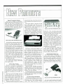


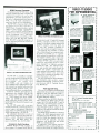


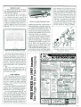


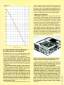
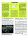


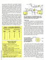


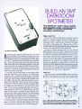
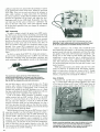
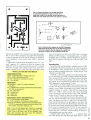


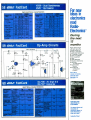

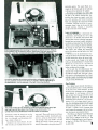

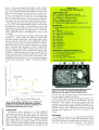


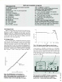
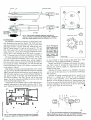

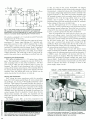
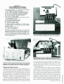


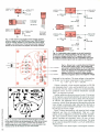
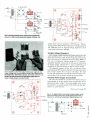
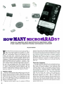


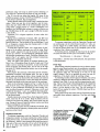


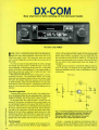
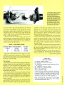
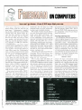
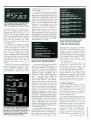

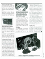

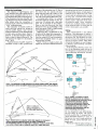


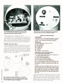
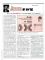


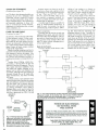

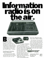


![TS-990S - [::] Kenwood ASC](http://vs1.manualzilla.com/store/data/006244915_1-7faa742287d221f7966f9657fbac9f9a-150x150.png)