1
Freescale Semiconductor, Inc.
Order by AN1940/D
(Motorola Order Number)
Rev. 0, 3/02
ARCHIVED BY FREESCALE SEMICONDUCTOR, INC. 2005
Mapping ADC Control
Registers to the SDK API
Contents
1. Introduction.................................... 1
2. ADC Registers ...............................1
2.1 ADC Control Register 1 (ADCR1) .2
2.2 ADC Control Register 2 (ADCR2) .5
2.3 Zero Crossing and Out of Range
Limit Registers ................................5
2.4 Channel List and Sample Disable
Registers (ADLST1, ADLST2,
ADSDIS) .........................................6
1.
Introduction
How does the API defined for the ADC in Section 5.4 of the
SDK Manual Targeting Motorola 56F80X Platform relate
to the description of ADC operation discussed in Section 9 of
the DSP56F80X User’s Manual?
First, the SDK Manual describes the ADC from a software
perspective while the User’s Manual describes the ADC from
a hardware point of view. The SDK Manual describes the
ADC from a C language perspective while the User’s Manual
tells the reader what bits do what in the memory map. This
application note provides a bridge between these two
perspectives.
2.
3. Programming Examples................. 9
3.1 How To Tell Whether an Example
Works...............................................9
3.1.1 Loop Mode Examples...............10
3.1.2 Once Mode Examples...............10
3.1.3 Triggered Mode Examples .......10
3.2 Suitability for Other EVMs...........11
3.2.1 56F805 EVM ............................11
3.2.2 56F803 EVM ............................11
4. For a Deeper Look ....................... 12
ADC Registers
There are ten different ADC register types, with 33 separate
ADC registers. In the SDK most of the setup of the ADC
module is accomplished via the settings (mostly in the
appconfig.h) of 11 different types of #define tokens. There is
also a data structure defined in Table 5-26 of the Targeting
Manual, that is used by the SDK open function. Parameters
determined in the appconfig.h are static in the application,
while those parameters determined by the open statement can
be changed. In addition to these parameters of the open
statement, the SDK primitive ioctl can be used to start/stop
the ADC, set the ADC clock, enable/disable callbacks, and
more.
Table 2-1 shows the eleven types of ADC registers. Let’s
begin our exploration of the map between ADC register and
SDK API with ADC Control Register 1.
© Motorola, Inc., 2002. All rights reserved.
For More Information On This Product,
Go to: www.freescale.com
Mapping ADC Control Registers
to the SDK API
ARCHIVED BY FREESCALE SEMICONDUCTOR, INC. 2005
Freescale Semiconductor, Inc...
Michael W. Mann
Freescale
Semiconductor,
Inc.
ARCHIVED
BY FREESCALE
SEMICONDUCTOR,
INC. 2005
ADC Registers
Table 2-1. ADC Registers for the DSP56F80x
ARCHIVED BY FREESCALE SEMICONDUCTOR, INC. 2005
Freescale Semiconductor, Inc...
Name
ADC Control Registers 1 and 2
ADC Zero Crossing Register
ADC Channel List Registers 1 and 2
ADC Sample Disable Register
ADC Status Register
ADC Limit Status Register
ADC Zero Crossing Status Register
ADC Result Registers 0-7
ADC Low Limit Registers 0-7
ADC Offset Registers 0-7
Acronym
ADCR1 and ADCR2
ADZCC
ADLST1 and ADLST2
ADSDIS
ADSTAT
ADLSTAT
ADZCSTAT
ADRSTL0-7
ADCLLMT0-7
ADOFS0-7
2.1 ADC Control Register 1 (ADCR1)
ADC_BASE+$0
15
Read
0
Write
Reset
0
14
STOP
1
13
12
0
START
0
11
10
9
8
7
SYNC EOSIE ZCIE LLMTIE HLMTIE
1
0
0
0
0
6
5
4
CHNCFG[3:0]
0
0
0
3
0
0
0
2
1
0
SMODE[2:0]
1
0
1
For each register field shown above, we will discuss the equivalent construct in the SDK’s API for the
ADC driver.:
Register Field
SMODE[2:0] =
000
001
010
011
100
101
110 (reserved)
111 (reserved)
CHNCFG[3:0]
[0] = 1
[1] = 1
[2] = 1
[3] = 1
SDK API Equivalent
#define ADC{|A|B}_SCANMODE=
ADC_SEQUENTIAL_ONCE
ADC_ONCE_SIMULTANEOUS
ADC_SEQUENTIAL_LOOP
ADC_SIMULTANEOUS_LOOP
ADC_SEQUENTIAL_TRIGGERED
ADC_SIMULTANEOUS_TRIGGERED
#define ADC{|A|B}_DIFFERENTIAL_01
#define ADC{|A|B}_DIFFERENTIAL_23
#define ADC{|A|B}_DIFFERENTIAL_45
#define ADC{|A|B}_DIFFERENTIAL_67
Note: Braces denote options in the naming of the define token. The 56F801/3/5 DSPs each have a
single analog to digital converter (ADC) module named ADCA, while the 56F807 has two ADC
modules, named ADCA and ADCB. Since the SDK API must support all of theses DSPs, many SDK
token names have multiple forms. Typically a token is of the form ADC_name for ‘801-805 and
ADCA_name plus ADCB_name for the ‘807. For example ADC{|A|B}_SCANMODE represents
three tokens: ADC_SCANMODE, ADCA_SCANMODE, and ADCB_SCANMODE.
Since the SDK API equivalents shown above are all of the form “#define TOKEN” in the appconfig.h
file, these configurations are static - done once at the build of the application.
Register Field
HLMTIE = 0
HLMTIE = 1
2
SDK API Equivalent
default
#define ADC_RAW_HIGH_LIMIT_CALLBACK HighCallbackFunction
Mapping ADC Control Registers to ADK API
For More Information On This Product,
Go to: www.freescale.com
MOTOROLA
Freescale
Semiconductor,
Inc.
ARCHIVED
BY FREESCALE
SEMICONDUCTOR,
INC. 2005
ADC Registers
While #define ADC_RAW_HIGH_LIMIT_CALLBACK in the appconfig.h file is equivalent to
“HLMTIE = 1”, it does more than simply turn on HLMTIE. It also installs an interrupt vector to an
ISR executive that handles Zero Crossing, High Threshold, and Low Threshold interrupts. This ISR,
installed at vector table address $0072 (ADCA) or $0070 (ADCB) checks which type of interrupts are
active by checking the HLMTI, LLMTI, and ZCI bits in the ADC Status Register (ADCSTAT).
The C function prototype of all callback functions is:
ARCHIVED BY FREESCALE SEMICONDUCTOR, INC. 2005
Freescale Semiconductor, Inc...
void
myCallbackFunction(
adc_eCallbackType Type,
adc_tSampleMask CausedSampleMask)
typedef enum{
ADC_ZERO_CROSSING,
ADC_LOW_LIMIT,
ADC_HIGH_LIMIT,
ADC_CONVERSION_COMPLETE,
}
adc_eCallbackType
typedef
UWord16
adc_tCallbackType
The least significant byte of CausedSampleMask identifies which analog channel(s) caused the
interrupt(s). This information is taken from the ADC Limit Status Register (ADLSTAT) and the ADC
Zero Crossing Status Register (ADZCSTAT). So when coding the callback function used, you can
check the first argument Type, using the enumeration define above, to see what type of event has
occurred. If you use different call back functions for each call back type you don’t need to check this
argument. If you service more than one event with the same call back function, for example both low
and high thresholds, then you must check this argument. Check the second argument,
CausedSampleMask, to determine which channel or channels caused the interrupts.
The support for the low limit interrupt, equivalent to the high limit interrupt, is given by:
Register Field
LLMTIE = 0
LLMTIE = 1
SDK API Equivalent
default
#define ADC_RAW_LOW_LIMIT_CALLBACK LowCallBackFunction
As with the high level callback, the definition of a low level callback also installs the same interrupt
executive discussed above.
Support for the zero crossing interrupt is given by:
Register Field
ZCIE = 0
ZCIE = 1
SDK API Equivalent
default
#define ADC_RAW_ZERO_CROSSING_CALLBACK ZeroCrossCallBack
As with the high and low level callbacks, the definition of a zero crossing callback also installs the
same interrupt executive discussed above.
All of these interrupts are serviced through the same entry in the interrupt table:
or
$0072
$0070
ADCA Zero Crossing or Limit Error
ADCB Zero Crossing or Limit Error (DSP56F807 only)
The default interrupt priority level is 1, but you can set other priorities in the appconfig.h to support
interrupt nesting by including additional lines by:
#define
#define
GPR_INT_PRIORITY_57 N //ADCA
GPR_INT_PRIORITY_56 N //ADCB (DSP56F807 only)
where N is an integer between 1 and 7.
MOTOROLA
Mapping ADC Control Registers to the SDK API
For More Information On This Product,
Go to: www.freescale.com
3
Freescale
Semiconductor,
Inc.
ARCHIVED
BY FREESCALE
SEMICONDUCTOR,
INC. 2005
ADC Registers
Processing after the completion of an ADC scan is supported by:
Register Field
SDK API Equivalent
EOSIE = 0
default
EOSIE = 1
#define ADC_RAW_CONVERSION_COMPLETE_CALLBACK EndofScanCallbackFunction
This callback is served by ISRs at vector locations 55 (ADCA) or 54 (ADCB):
$0055
$0054
or
ADCA Conversion Complete
ADCB Conversion Complete (DSP56F807 only)
The default priority level is 1, but you can set other priorities in the appconfig.h by:
GPR_INT_PRIORITY_55 N //ADCA
GPR_INT_PRIORITY_54 N //ADCB (DSP56F807 only)
where N is an integer between 1 and 7.
Callback functions are evoked using the SDK’s interrupt dispatcher. This interrupt dispatcher provides
full context saving for interrupt service routines so that they can be written in C. Users desiring to
minimize interrupt latency while using C may use the SDK’s superfast interrupt support by defining a
C token in the appconfig.h file:
ARCHIVED BY FREESCALE SEMICONDUCTOR, INC. 2005
Freescale Semiconductor, Inc...
#define
#define
#define
#define
ADC_A_CALLBACK_USES_PRAGMA_INTERRUPT
ADC_B_CALLBACK_USES_PRAGMA_INTERRUPT //DSP56F807
Then a #pragma interrupt must appear in all callback code, including not only the callback routines,
but also all go routines called by them. For more information on interrupt support within the SDK see
Chapter 7 of the Embedded SDK Programmer’s Guide.
You can bypass the SDK’s interrupt dispatcher by programing the call back function in C and
installing the call back directly into the interrupt table as a superfast interrupt. For examples of this see
the source code for the Simultaneous Triggered - Two µs example discussed below.
SDK support for the SYNC, START, and STOP fields is given by:
Register Field
SYNC = 0
SYNC = 1
START = 0
START = 1
STOP = 1
STOP = 0
SDK API Equivalent
#define ADC_INITIATE_SCAN_ON_START //default
#define ADC_INITIATE_SCAN_ON_SYNC
also ioctl(ADC_FD, {ADC_SYNC_OFF | ADC_SYNC_ON}, NULL)
N/A - this bit is only set to one to start a scan
ioctl(ADC_FD, ADC_START, NULL)
ioctl(ADC_FD, ADC_STOP, NULL)
N/A - this bit is set to one to stop a scan
Where the file descriptor, ADC_FD has been assigned by an open call. Note that the file descriptor,
ADC_FD, relates to a single analog input. This call to ioctl changes ADC behavior for all other
channels that have been opened!
This call affects all open ADC channels even though the ADC_FD argument only applies to single
input channel.
There is no corresponding SDK call to un-stop the ADC once it has been stopped. The only way to
un-stop this bit is to use periphBitSet or close and then reopen all input channels.
4
Mapping ADC Control Registers to ADK API
For More Information On This Product,
Go to: www.freescale.com
MOTOROLA
Freescale
Semiconductor,
Inc.
ARCHIVED
BY FREESCALE
SEMICONDUCTOR,
INC. 2005
ADC Registers
2.2 ADC Control Register 2 (ADCR2)
ADC_BASE+$1
15
14
13
12
11
10
9
8
7
6
5
4
Read
0
0
0
0
0
0
0
0
0
0
0
0
0
0
0
0
0
0
0
0
0
0
0
0
3
1
0
DIV[3:0]
Write
Reset
2
0
1
1
1
Please note that the ioctl call affects all open ADC channels (all ADC file descriptors) even though the
first argument is the file descriptor of one channel. Clock divisors should be in the range of 1-15, either
as an integer constant in the #define or as an argument to the ioctl call.
ARCHIVED BY FREESCALE SEMICONDUCTOR, INC. 2005
Freescale Semiconductor, Inc...
Register Field
SDK API Equivalent
DIV[3:0] = 1 (default value of SDK)
= 7 (default value of field at reset)
= N #define ADC_CLOCK_DIVISOR N
or ioctl(ADC_FD, ADC_SET_DIVISOR, N)
2.3 Zero Crossing and Out of Range Limit Registers
Name
ADC Zero Crossing Control Register
ADC Offset Registers 0-7
ADC Low Limit Registers 0-7
ADC High Limit Registers 0-7
Acronym
ADZCC
ADOFS0-7
ADLLMT0-7
ADHLMT0-7
Fields
ZCEi[1:0], i=0,...,7
OFFSET[11:0]
LLMT[11:0]
HLMT[11:0]
These fields are determined by the adc_sState data structure passed as the third argument of the open
call. A typical declaration for this data structure is:
static const adc_sState sAdc1 = {
/*Analog Channel = */ ADC_CHANNEL_6,
/*Open SampleMask = */ 0X0
/*Channel Offset = */ FRAC16(0.5),
/*Low Limit = */ FRAC16(0.25),
/*High Limit =*/ FRAC16(0.75),
/*Zero Crossing Type = */ ADC_ZC_DISABLE
}
//Channel 6 used
//Assigned to Sample 0 in ADC scan
//OFFSET[11:0] in ADOFS0
//LLMT[11:0] in ADLLMT0
//HLMT[11:0] in ADHLMT0
//ZCE0[1:0] in ADCZCC
Possible values for Analog Channel are C tokens of the form ADC_CHANNEL_N where
N = 0, 1, 2...7. (The example above has N = 6.) This member of the ADC state data structure identifies
which ADC input pin is mapped to the file descriptor returned by the open call.
Possible values for zero crossing type are:
Register Field
SDK API Equivalent
ZCEi[1:0] = 00 /*Zero Crossing Type = */ ADC_ZC_DISABLE
= 01
ADC_ZC_POSITIVE_NEGATIVE
= 10
ADC_ZC_NEGATIVE_POSITIVE
= 11
ADC_ZC_ANY
The ADC module can capture up to eight single-ended inputs and up to four differential inputs. The
mapping of input pin(s) to sample is totally arbitrary save for a few rules:
1. Differential inputs use consecutive pins. E.G.: pins AN0 (+) and AN1(-) support one differential input.
2. In simultaneous sampling mode, the same pin can’t be assigned to both inputs of a sample pair.
3. Each sample can service just one input. It’s impossible to do otherwise when programming the ADC’s
Channel List Registers, but it is possible to misprogram it via the SDK’s API. When a duplicate
sample assignment is encountered, the SDK open routine will return a file descriptor of -1, showing
that the open was unsuccessful.
MOTOROLA
Mapping ADC Control Registers to the SDK API
For More Information On This Product,
Go to: www.freescale.com
5
Freescale
Semiconductor,
Inc.
ARCHIVED
BY FREESCALE
SEMICONDUCTOR,
INC. 2005
ADC Registers
2.4 Channel List and Sample Disable Registers (ADLST1, ADLST2, ADSDIS)
To explore the relationship between the SAMPLEi:[2:0] fields in the ADC Channel List Registers
(ADLST1, ADLST2), the ADC Sample Disable Register (ADSDIS), and the OpenSampleMask values
in each ADC open call, it helps to map out the relationship between analog input pin and sample order.
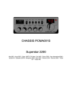
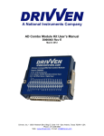
The Excel spreadsheet “Pin to SampleMap.xls”1 provides a tool that we can use to determine
OpenSampleMasks based on Pin-Sample assignments (see Figure 2-1). The spreadsheet has added
“smarts” to prevent problems such as premature termination of scans because of disabled samples. The
spreadsheet does not, however, flag when the same analog pin is assigned to both samples of a
simultaneous sample pair.
Analog Input Pin
0
i=
0
Seq Sample #:
0a
Sim Sample #:
AN0
1
AN1
AN2
AN3
AN4
AN5
AN6
AN7
Assignment OK?: TRUE
SAMPLEi [2:0]: 000
Seq Sample Enabled?: TRUE
Sim Sample Enabled?: TRUE
ARCHIVED BY FREESCALE SEMICONDUCTOR, INC. 2005
Freescale Semiconductor, Inc...
ADC Pin-Sample Map:
appconfig.h:
#define
#define
#define
#define
#define
#define
#define
#define
Input 1 to assign channel, blank or zero otherwise
1
1
1a
2
2
2a
3
3
3a
4
4
0b
5
5
1b
6
6
2b
7
7
3b
1
1
1
1
1
1
TRUE
001
TRUE
010
TRUE
011
TRUE
100
TRUE
101
TRUE
110
1
TRUE
111
TRUE
TRUE
TRUE
TRUE
TRUE
TRUE
TRUE
TRUE
TRUE
TRUE
Open
Sample
Mask
0x 0
0x 0
0x 0
0x 0
0x 1
0x 2
0x 4
0x 8
1
2
4
8
0
0
0
0
N.B.:Replace ? with A or B. E.G.: INCLUDE_ADCA_SAMPLE_1
INCLUDE_ADC?_SAMPLE_0
INCLUDE_ADC?_SAMPLE_1
INCLUDE_ADC?_SAMPLE_2
INCLUDE_ADC?_SAMPLE_3
INCLUDE_ADC?_SAMPLE_4
INCLUDE_ADC?_SAMPLE_5
INCLUDE_ADC?_SAMPLE_6
INCLUDE_ADC?_SAMPLE_7
Figure 2-1. Example Pin-Sample Map
The rows of this table indicate the analog input pin while the columns indicate the sample number. The
column index differs depending on whether the ADC is in sequential or simultaneous sampling mode.
Sequential samples are indexed from 0 to 7 while simultaneous samples come in pairs, here indexed
from 0 to 3. An “a” suffix means the first sample of a sample pair and “b” marks the second. At any
(input pin, sample) row-column intersection the user can input a 1 to allocate that sample number to
that row’s analog input pin.
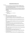
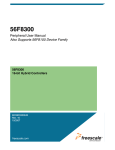
Figure 2-2 shows that it is possible to capture all eight samples from the same input pin. Note that this
is not a valid configuration for simultaneous mode operation, since the same input (AN0) is used for
both halves of a sampling pair
1. You can find this spreadsheet and the examples mentioned in 3. Programming Examples by searching
through the 56800 FAQs (http://e-www.motorola.com/cgi-bin/faq.cgi?kbase=dsp&prod_default=56800)
using the category A/D Converter Module.
6
Mapping ADC Control Registers to ADK API
For More Information On This Product,
Go to: www.freescale.com
MOTOROLA
Freescale
Semiconductor,
Inc.
ARCHIVED
BY FREESCALE
SEMICONDUCTOR,
INC. 2005
ADC Registers
.
A D C P in-Sam ple M ap:
appconfig.h:
#de fine
#de fine
#de fine
#de fine
#de fine
#de fine
#de fine
#de fine
#de fine
Input 1 to assign channel, blank or zero otherw ise
1
1
1a
1
2
2
2a
1
3
3
3a
1
4
4
0b
1
5
5
1b
1
6
6
2b
1
7
7
3b
1
TR U E
000
TR U E
000
TR U E
000
TR U E
000
TR U E
000
TR U E
000
TR U E
000
TR U E
TR U E
TR U E
TR U E
TR U E
TR U E
TR U E
TR U E
TR U E
TR U E
O pen
S am ple
M ask
0x F
F
N .B .:R eplace ? w ith A or B . E .G .: INCLUD E_ADCA_S AMPLE_1
AD C? QUEUE DEPTH ( 16*8)
IN CLUDE_AD C?_SAMPL E_0
IN CLUDE_AD C?_SAMPL E_1
IN CLUDE_AD C?_SAMPL E_2
IN CLUDE_AD C?_SAMPL E_3
IN CLUDE_AD C?_SAMPL E_4
IN CLUDE_AD C?_SAMPL E_5
IN CLUDE_AD C?_SAMPL E_6
IN CLUDE_AD C?_SAMPL E_7
Figure 2-2. Pin-Sample Map for Eight Samples on an Input
A D C P in -S am p le M ap :
i=
S e q S am p le #:
S im S a m p le #:
AN0
AN1
AN2
AN3
AN4
AN5
AN6
AN7
A ssign m e n t O K ? :
S A M P L E i [2 :0 ]:
S e q S a m p le E n a ble d ? :
S im S a m p le E n a ble d ? :
Analog Input Pin
ARCHIVED BY FREESCALE SEMICONDUCTOR, INC. 2005
Freescale Semiconductor, Inc...
Analog Input Pin
0
i=
0
S eq S am ple #:
0a
S im S am ple #:
AN0
1
AN1
AN2
AN3
AN4
AN5
AN6
AN7
A ssignm ent O K ?: TR U E
S A M P LE i [2:0]:
000
S eq S am ple E nabled?: TR U E
S im S am ple E nabled?: TR U E
a p p co n fig .h :
#define
#define
#define
#define
#define
#define
#define
#define
#define
Input 1 to assign channel, blank or zero otherw ise
0
0
0a
1
TRUE
00 0
1
1
1a
1
TRUE
000
2
2
2a
1
TRUE
000
3
3
3a
1
4
4
0b
5
5
1b
6
6
2b
7
7
3b
1
1
1
1
TRUE
000
TRUE
001
TRUE
001
TRUE
001
TRUE
001
TR U E
TR U E
TRUE
TR U E
TR U E
TRUE
TR U E
TRUE
TR U E
TRUE
TR U E
TRUE
O pen
S a m p le
M ask
0x 0
0x F
F
0
N .B .:R e p la ce ? w ith A o r B . E .G .: I N C L U D E _ A D C A _ S A M P L E _ 1
ADC? QUEUE DEPTH (16*4)
INCLUDE_ADC?_SAMPLE_0
INCLUDE_ADC?_SAMPLE_1
INCLUDE_ADC?_SAMPLE_2
INCLUDE_ADC?_SAMPLE_3
INCLUDE_ADC?_SAMPLE_4
INCLUDE_ADC?_SAMPLE_5
INCLUDE_ADC?_SAMPLE_6
INCLUDE_ADC?_SAMPLE_7
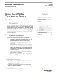
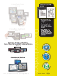
Figure 2-3. Simultaneous Sampling Mode Equivalent to Figure 2-2
- Four Samples on Each Input
MOTOROLA
Mapping ADC Control Registers to the SDK API
For More Information On This Product,
Go to: www.freescale.com
7
ADC Registers
Freescale
Semiconductor,
Inc.
ARCHIVED
BY FREESCALE
SEMICONDUCTOR,
INC. 2005
A D C P in -S am p le M ap :
app config.h :
ARCHIVED BY FREESCALE SEMICONDUCTOR, INC. 2005
Input 1 to assign channel, blank or zero otherw ise
0
0
0a
1
1
1
1a
TR UE
0 00
TRUE
2
2
2a
TRUE
3
3
3a
4
4
0b
5
5
1b
6
6
2b
7
7
3b
TRUE
TRU E
TRU E
TR UE
TRUE
F AL S E
F AL S E
F AL S E
F AL S E
TR UE
F AL S E
F AL S E
F AL S E
F AL S E
F AL S E
F AL S E
F AL S E
O p en
S am p le
M ask
0x 0
1
N .B .:R e place ? w ith A or B . E .G .: INCLU DE_ADC A_SAM PLE_1
#def ine I NCLUD E_ADC? _SAMP LE_0
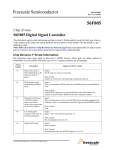
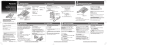
Figure 2-4. Single Input Sample Captured
ADC Pin-Sample Map:
0
i=
0
Seq Sample #:
0a
Sim Sample #:
AN0
1
AN1
AN2
AN3
AN4
AN5
AN6
AN7
Assignment OK?: TRUE
SAMPLEi [2:0]: 000
Seq Sample Enabled?: TRUE
Sim Sample Enabled?: TRUE
Input 1 to assign channel, blank or zero otherwise
1
1
1a
2
2
2a
3
3
3a
Analog Input Pin
Freescale Semiconductor, Inc...
Analog Input Pin
i=
S eq S am p le # :
S im S am p le # :
AN0
AN1
AN2
AN3
AN4
AN5
AN6
AN7
A ssignm ent O K ?:
S A M P LE i [2:0]:
S e q S am ple E nable d?:
S im S am ple E nable d?:
appconfig.h:
4
4
0b
5
5
1b
6
6
2b
7
7
3b
1
TRUE
TRUE
TRUE
TRUE
001
TRUE
TRUE
TRUE
FALSE
FALSE
FALSE
FALSE
FALSE
FALSE
FALSE
FALSE
FALSE
FALSE
Open
Sample
Mask
0x 0
0x 1
1
0
N.B.:Replace ? with A or B. E.G.: INCLUDE_ADCA_SAMPLE_1
#define INCLUDE_ADC?_SAMPLE_0
#define INCLUDE_ADC?_SAMPLE_4
Figure 2-5. Simultaneous Sampling Mode Case Equivalent to Figure 2-4.
8
Mapping ADC Control Registers to ADK API
For More Information On This Product,
Go to: www.freescale.com
MOTOROLA
Freescale
Semiconductor,
Inc.
ARCHIVED
BY FREESCALE
SEMICONDUCTOR,
INC. 2005
Programming Examples
Note, however, it is possible to capture 4 simultaneous mode samples at once. This is shown in
Figure 2-3.
So why is this of interest? By operating the ADC at a clock rate much faster than the targeted signal,
we can oversample and then average. Assuming that white noise predominates in the targeted signal
(as opposed to coherent noise), averaging four samples can improve the ADC’s SNR by 6 dB.
Averaging 8 samples can improve SNR by nearly 9 dB.
To sample an input more than once in each ADC scan you must increase the ADC’s queue depth. The
default is 16 bits, sufficient for only one sample. In your appconfig.h file you should increase this
default accordingly:
#define NUM_SAMPLES 8 //for Figure 2-2, 4 for Figure 2-3
#define ADCA_QUEUE_DEPTH 16*NUM_SAMPLES
ARCHIVED BY FREESCALE SEMICONDUCTOR, INC. 2005
Freescale Semiconductor, Inc...
Then each read statement should pass a vector NUM_SAMPLES long instead of a scalar.
WARNING: The ADC driver does not support storing samples from past ADC scans in some sort of
FIFO buffering. The only buffering provided is for the case that the same input pin is sampled more
than once.
Figure 2-4 and Figure 2-5 show the simplest ADC channel assignments for sequential and
simultaneous modes, respectively.
3.
Programming Examples
There are twelve examples of how to use the SDK’s ADC drivers. You can obtain the source code for
them at the FAQ website.
Examples are classified by the ADC mode used:
• Loop Mode
• Once Mode
• Triggered Mode
For each mode category there are examples for both sequential and simultaneous sampling methods.
3.1 How To Tell Whether an Example Works
Each sample lights an LED when an input channel is high (+3.3V) and turns the LED off when the
input channel is low (ground). You can directly jumper +3.3V or ground to each input pin or you can
use the EVM’s switches (GP1, GP2, and the Run/Stop Switch).
The GP1 and GP2 switches are normally high; depressing them will bring the input pin low and turn
off the LED. The Run/Stop switch can bring the input pin high or low depending on its state. All three
switches are available from the J23 Connector on the 56F807 EVM.
The pin assignments for ADC-A (J9) and ADC-B (J12) are:
AN0 AN1 AN2 AN3 GND -
MOTOROLA
J9
1
2
3
4
5
6
7
8
9 10
- AN4
- AN5
- AN6
- AN7
- +3.3VA
J12
AN8 - 1
2
AN9 - 3
4
AN10 - 5
6
AN11 - 7
8
GND - 9 10
- AN12
- AN13
- AN14
- AN15
- +3.3VA
Mapping ADC Control Registers to the SDK API
For More Information On This Product,
Go to: www.freescale.com
9
Freescale
Semiconductor,
Inc.
ARCHIVED
BY FREESCALE
SEMICONDUCTOR,
INC. 2005
Programming Examples
The pin assignments of interest for Port D (J23) are:
GND
GP2
|
|
7
8
5
6
3
4
|
|
|
+3.3V
R/S
GP1
1
2
J23
3.1.1 Loop Mode Examples
ARCHIVED BY FREESCALE SEMICONDUCTOR, INC. 2005
Freescale Semiconductor, Inc...
1. Sequential Loop
The test case “Sequential Loop” demonstrates ADC operation using the SDK ADC driver in a ‘loop
sequential’ mode. In this mode, the ADC sample cycle runs continually and asynchronously from the
application code which reads in the ADC samples. No interrupts nor function callbacks are used. The
SDK primitive ioctl is used to read in samples instead of read. Analog input pins AN0 and AN3 are
used.
2. Simultaneous Loop
The test case “Simultaneous Loop” demonstrates ADC operation using the SDK ADC driver in a ‘loop
simultaneous’ mode. In this mode, the ADC sample cycle runs continually and asynchronously from
the application code which reads in the ADC samples. No interrupts or function callbacks are used.
The SDK primitive ioctl is used to read in samples instead of read. Analog input pins AN0 and AN4
are simultaneously sampled.
3.1.2 Once Mode Examples
1. Once Simultaneous
This test case demonstrates ADC operation using the SDK ADC driver in a ‘once simultaneous’ mode
In this mode the ADC sample cycle is started with an explicit START command. An interrupt signals
the end of the cycle via a boolean flag ScanComplete. Samples are read when ScanComplete is true.
Analog input pins AN0 and AN4 are simultaneously sampled.
2. Simultaneous Once Two Pair
This example provides simultaneous samples of two different signal pairs. The ADC sample cycle is
started with an explicit START command. An interrupt signals the end of the cycle via a boolean flag
ScanComplete. Samples are read when ScanComplete is true. Analog input pins AN0/AN4 and
AN2/AN5 are simultaneously sampled.
3. Simultaneous Once Two Different Pair
A reprise of the previous example using different input signals.
4. Sequential Once Three Channel
This example provides sequential sampling of three input pins: AN0, 1, 7. The green, yellow, and red
LEDs show the state of each input pin.
3.1.3 Triggered Mode Examples
1. Simultaneous Triggered
This test case demonstrates ADC operation using the SDK ADC driver in a ‘triggered simultaneous’
mode. In this mode, the Quad Timer C-2 drives the ADC SYNC pulse at a 1 ms rate in order to
demonstrate the basic operation for triggered simultaneous mode. An ADC driver callback (interrupt
service routine, or ISR) is used to call an SDK function which reads the ADC samples after the end of
each scan. A while(1) loop in the main program merely monitors the state of the sampled values in two
global variables shared with the ISR. Analog input pins AN0 and AN4 are used.
10
Mapping ADC Control Registers to ADK API
For More Information On This Product,
Go to: www.freescale.com
MOTOROLA
Freescale
Semiconductor,
Inc.
ARCHIVED
BY FREESCALE
SEMICONDUCTOR,
INC. 2005
Programming Examples
2. Sequential Triggered Three Channels
A variation of the previous case, where three input pins (AN0, 1, 2) are sampled sequentially.
3. Simultaneous A and Sequential B Triggered
Simultaneous samples are taken from ADC-A while sequential samples are taken from ADC-B. Two
different ISRs (one for each ADC) are used to read data into global variables after the end of each
ADC scan. Input pins AN0 and AN1 are sampled on ADC-A and input pin AN8 is sampled on
ADC-B.
4. Simultaneous Triggered - Two µs
ARCHIVED BY FREESCALE SEMICONDUCTOR, INC. 2005
Freescale Semiconductor, Inc...
This test case demonstrates ADC operation using the ‘triggered simultaneous’ mode running at a
2 µs sampling period. The structure of this test case is very much like the Simultaneous Triggered test
case, however changes have been made to improve performance:
•
Running from Flash instead of External RAM
•
Increasing the clock rate (PLL_MUL) to 80 MHz from 72 MHz
•
Using a superfast ISR written in Assembly to read the ADC samples
•
Using low level driver calls (not strictly necessary, but it does reduce the memory footprint)
•
Moving constant data into Flash using appconst.c (good programming practice)
•
Changing the ADC clock divisor to 3 from 4 (please examine the appconfig.h parameters)
5. Sequential Triggered With Average
This example shows how to oversample an input channel at the ADC scan rate, averaging eight
samples in to reduce noise. The ADC is triggered at a 1ms clock period. Input pin AN0 is sampled.
6. Simultaneous Triggered With Average
This example is a variant of the Simultaneous Triggered - 2 µs case. Here, four samples are taken for
each input signal in the simultaneous signal pair and the samples are averaged in an assembly ISR to
produce a single pair of output signals for teach ADC scan. The ADC is triggered at a 1 ms clock
period (1000 Hz sample rate). Input pins AN0/AN4 are used.
3.2 Suitability for Other EVMs
3.2.1 56F805 EVM
Only the “3-Simultaneous A & Sequential B Triggered” project requires the two ADCs of an 807
EVM, so all others can be easily ported to 56F805 EVMs just by moving the appconfig.h, appconst.c
and main.c (or equivalent) into a new SDK 56F805 stationary project.
The pin assignments for ADC-A (J9) and Port D (J4) are:
+3.3VA AN7 AN6 AN5 AN4 -
10
8
6
4
2
9
7
5
3
1
J9
- GND
- AN3
- AN2
- AN1
- AN0
J4
1
3
GP2 - 5
GND - 7
2
4 - GP1
6 - R/S Switch
8 - +3.3VA
3.2.2 56F803 EVM
Since these projects use more than one LED, it is difficult to use them on 56F803 EVMs because there
is only one LED (green).
MOTOROLA
Mapping ADC Control Registers to the SDK API
For More Information On This Product,
Go to: www.freescale.com
11
4.
Freescale
Semiconductor,
Inc.
ARCHIVED
BY FREESCALE
SEMICONDUCTOR,
INC. 2005
For a Deeper Look
If you are interested in how the ADC driver is implemented in the SDK you should look in these files:
Table 4-1 ADC Driver Support Files
File
config.c
config.h
const.c
ARCHIVED BY FREESCALE SEMICONDUCTOR, INC. 2005
Freescale Semiconductor, Inc...
const.h
adc.h
arch.h
Comments
Definition of buffer space for each input channel based on INCLUDE_ADC?_SAMPLE_N tokens.
Defines default static configurations for ADC if INCLUDE_ADC is defined (cleans up after
appconfig.h). Sets up ISRs for ADC callbacks. If user does not statically install ISRs in the vector
table then it takes care of this within the context of the SDK. If callbacks are defined then config.h
also provides extern declarations for the callback routines so that they can be seen during link.
Builds the ADC Samle Disable Register (ADSDIS) from the defined INCLUDE_ADC?_SAMPLE_N
tokens found on the appconfig.h. Creates array data structures used to control each open ADC
channel.
Declares ADC data structures extern so that they are available outside of const.c source file.
Provides the typedefs and defines needed to use SDK ADC driver software.
Defines typedef structure arch_sADC that provides a C structure that mimics the memory map of
ADC peripheral registers.
Other files that support the ADC:
\bsp\adcdrv.h, \bsp\adcdrv.c, \bsp\adcdrvIO.h, \bsp\adcdrvIO.h
Motorola reserves the right to make changes without further notice to any products herein. Motorola makes no warranty, representation or guarantee regarding the
suitability of its products for any particular purpose, nor does Motorola assume any liability arising out of the application or use of any product or circuit, and
specifically disclaims any and all liability, including without limitation consequential or incidental damages. “Typical” parameters which may be provided in Motorola
data sheets and/or specifications can and do vary in different applications and actual performance may vary over time. All operating parameters, including
“Typicals” must be validated for each customer application by customer’s technical experts. Motorola does not convey any license under its patent rights nor the
rights of others. Motorola products are not designed, intended, or authorized for use as components in systems intended for surgical implant into the body, or other
applications intended to support or sustain life, or for any other application in which the failure of the Motorola product could create a situation where personal injury
or death may occur. Should Buyer purchase or use Motorola products for any such unintended or unauthorized application, Buyer shall indemnify and hold Motorola
and its officers, employees, subsidiaries, affiliates, and distributors harmless against all claims, costs, damages, and expenses, and reasonable attorney fees
arising out of, directly or indirectly, any claim of personal injury or death associated with such unintended or unauthorized use, even if such claim alleges that
Motorola was negligent regarding the design or manufacture of the part. Motorola and the Stylized M Logo are registered trademarks of Motorola, Inc. Motorola,
Inc. is an Equal Opportunity/Affirmative Action Employer.
MOTOROLA and the Stylized M Logo are registered in the US Patent & Trademark Office. All other product or service names are the property of their
respective owners. © Motorola, Inc. 2002.
How to reach us:
USA/EUROPE/Locations Not Listed: Motorola Literature Distribution; P.O. Box 5405, Denver, Colorado 80217. 1–303–675–2140 or 1–800–441–2447
JAPAN: Motorola Japan Ltd.; SPS, Technical Information Center, 3–20–1, Minami–Azabu. Minato–ku, Tokyo 106–8573 Japan. 81–3–3440–3569
ASIA/PACIFIC: Motorola Semiconductors H.K. Ltd.; Silicon Harbour Centre, 2 Dai King Street, Tai Po Industrial Estate, Tai Po, N.T., Hong Kong. 852–26668334
Technical Information Center: 1–800–521–6274
HOME PAGE: http://www.motorola.com/semiconductors/
For More Information On This Product,
Go to: www.freescale.com
AN1940/D