1
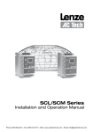
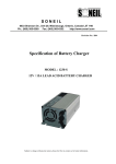
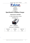
NF166
INSTALLATION AND USER MANUAL
WIRELESS REMOTE CONTROLLER AND ITS OPERATING FUNCTIONS
POWER : To turn On/Off the
TEMP : To allow adjust of Set-
air-conditioner,press to On,
next to OFF,and so on.
℃
℃
SLEEP : Press ON/OFF to allow 2
increase from Set-Temperature.
After each 1 hour will increase by 1 ;up
to 2hours by total of 2
℃
:To switch off automatically
TIMER
after setting timer off between
1~9 hours from press of button.
MODE : Operation selection AUTO or
COOL or DRY or FAN.
℃
Temperature by 1 up or
down between 16 to 32 .
TIME: To allow adjust of real time
or on/off timer.
SPEED : To set air flow to 4
different setting by each
press of button
【AUTO】→【 】→【 】→【 】
→【AUTO】
Difference between
Room and Set-Temp
AUTO
Speed
Above 3
HIGH
℃
℃
DIREC. : To adjust to swing and fix
MEDIUM
2~3
position of air flap.Press to
stop swing to fix position.
℃
℃
Below 2
LOW
OFF : To set off timer.
When press to set off timer,
the off timer will flash. .Then can
adjust the off timer.
AUTO : Auto to adjust position
of air flap.Press to swing
auto.
DEL. : To cancel on/off timer.
When on/off timer flash,press to
cancel on/off timer.
CLOCK : To set real time.
When press to set real time,
the real timer will flash.Then
can adjust the real time.
ACL : To reset the remote control.
ON : To set on timer.
When press to set on timer,
the on timer will flash.Then
can adjust the on timer.
ENT. : To enter on/off timer.
When on/off timer flash,
press to enter on/off
timer.
REMOTE SENSOR FUNCTIONS
LED Light indications:OFF Status:LED not lighted up
ON Status:Compressor OFF-Blinking
Compressor ON-LED lighted
Hole to receive output signal from wireless Remote Controller.
NF166
WIRING DIAGRAM
BLUE
220V
WHITE
TRANSFORMER
PRIMARY
BLACK
6-PIN:red wire put pin1
5-PIN:red wire put pin2
DC-FLAP
CA
CN1
● ACNH2
● H3
RECEIVER
BOX
1
COMP
H9
CN3
DISP
FLAP
ACL
H8
H7
HI
ME
TR/OP
TH
LO
CN2
CN5
THERMISTOR
YELLOW
BLACK
TRANSFORMER
SECONDARY
COIL
COM
BROWN
INDOOR UNIT
FAN MOTOR
NO
COMPRESSOR
START CAP.
L
(SM450-12---1.2uF)
N
EARTH
INSTALLATION POINTERS:
:
1.Please follow wiring connections strictly to wiring diagram provided.
2. In case of existing fan motor has only 2 speed,please connect PCB’s 【HI】
and 【Med】 wires together to fan motor’s【high-speed】wire connection.
3. Please check thoroughly all wiring connections to ensure correct connections
and voltage supply .Any wrong wiring will result in damaging PCB and
it shall not be warrantable.
START CAP.