1
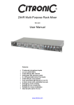
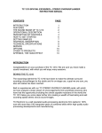
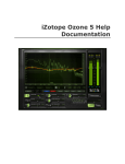
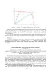
™
The SM500 Ultima Professional Mixing Desk
The SM500 Ultima is the first mixer in the Ultima range. The design is based on the immensely popular SM450 and comes
with a host of enhanced features to meet the needs of today’s medium sized installations.
The dual microphone facility features a comprehensive Mic override system ideal for radio microphones, 3-band
equalisation, balanced and unbalanced inputs as well as individual on-air buttons.
There are 4 CD, 3 Line and 3 Phono inputs routed to the four heavy duty music input faders via input gain, and shared EQ
controls for level matching. Channels 1 & 2 share a 3-band equaliser, as does 3 & 4, which is then routed to their respective
ends of the on-board VCA crossfader.
The music channel 3-band Eq can be internally installer defeated to prevent any additional Eq being added by the DJ once
the sound system has been set.
The SM500 Ultima also offers the main mixer output in either balanced XLR or unbalanced phono connectors, as well as
providing program mono and sub bass outputs. In addition a booth output is provided, which can be either full program or
music only. This is selected by an internal movable link and will prevent Mic feedback.
One of the SM500’s unique features is the re-positional connector panel, this allows the installer to easily rack the mixer into
a console or 19” rack. The connector panel can be moved to be on the rear of the unit or on the underside of the mixer,
making the SM500 Ultima the most versatile mixers in its range.
Important Safety Information
Warnings:
All the safety and operating instructions should be read before the appliance is operated.
To prevent fire or shock hazard, do not expose this appliance to rain or moisture.
To reduce the risk of electric shock, do not remove the cover (or back). There are no serviceable parts inside. Always
refer servicing to qualified service personnel.
Cautionary Notes:
Handle the power supply cord carefully. Do not damage or deform the power supply cord. If it is damaged or deformed,
it may cause electric shock or malfunction when used. When removing from wall outlet, be sure to remove by holding
the plug attachment and not by pulling the cord.
In order to prevent electric shock; do not open the top cover. If a problem occurs, contact your dealer.
Do not place metal objects or spill liquid inside the mixer. Electric shock or malfunction may result.
Any use of the controls, or any adjustment, or the performance of any procedure other than those specified herein may
result in serious damage to your health.
The mixer should not be opened or repaired by anyone except properly qualified service personnel.
Double insulated - when servicing, use only identical replacement parts.
™
Illustration
™
Features & Functions Top Panel
Microphone Section
1. Microphone Input
Two combination XLR & ¼” jack sockets are
mounted on the front face of the mixer for
connecting your balanced microphones.
Balanced Input wiring:
Tip: Pin2: Positive (HOT)
Ring: Pin3: Negative (COLD)
Sleeve: Pin1: Ground (SHIELD)
Input Impedance 2K Ohm
Input Sensitivity -56dB (1mV)
2. Microphone gain controls
Each microphone has it’s own gain control
allowing maximum microphone control and will
accommodate most microphones, both low and
high impedance’s to 600 Ohms.
3. Microphone EQ – Hi
This control allows 12dB of cut or boost to the
high frequencies and is shared between Mic 1 &
Mic 2.
4. Microphone EQ – Mid
This control allows 12dB of cut or boost to the mid
frequencies and is shared between Mic 1 & Mic 2.
5. Microphone EQ – Lo
This control allows 12dB of cut or boost to the low
frequencies and is shared between Mic 1 & Mic 2.
6. Microphone On Air Switches
Activates or de-activates the microphones without
the need to adjust the Gain Controls.
7. Microphone Manual Override Switch
When pressed the ‘live’ music program will be
attenuated by a pre-set level determined by the
‘depth’ control (8), thus allowing any microphone
signal to take priority on the main output
channels.
8. Override Depth Control
This control pre-sets the level of which the main
music program will be attenuated in either auto or
manual mode.
Attenuation range:
0dB (OFF) to -25dB.
To disable the override facility, simply turn the
control fully anticlockwise to OFF.
9. Override Sensitivity Control
This control enables ‘auto mic override’ and predetermines the threshold of microphone signal at
which the main music program will be ‘ducked’ in
‘auto override’ mode.
The higher the setting of this control the more
sensitive the ‘ducking’ threshold becomes.
NOTE: Changes in microphone gain or EQ will
have effect on this threshold. To disable auto
override turn control to ‘0’ i.e. fully anticlockwise.
Whenever the manual or auto override functions
are working, the ‘active’ led will illuminate.
Music Channels 1-4
Seven stereo line and 3 RIAA phono inputs are
arranged into 4 main music channels. These
channels in turn are arranged thus:
Channels 1 and 2 are sent to the left side of the
Citronic ‘Signature Pro’ Crossfader and channels
3 and 4 to the right. Before the crossfader, each
pair of channels shares a common path via a 3band equaliser section. The crossfade output is
then sent via the inserts to the final master level
controls to the mix O/P @ 0dB balanced and
unbalanced. In addition it is also sent to 2 mono
outputs of wide band and sub bass frequencies.
10. Input Gain Controls
Each main input channel has a gain control
offering infinity to +10dB gain range allowing
compensation for differing input levels.
11. Input Select Buttons
Channel 1 is a Line or CD type input. Channel 2 &
3 are CD or Phono/Line switchable, (rear panel),
inputs. Channel 4 is for Phono or CD type inputs.
12. Channel Fader
60mm quality faders control each channel
program level to the EQ and crossfader.
13. Cue Switches
The pre-fade input signal from each of the four
main music channels can be routed to the
headphone and VU display section of the mixer.
14. Music EQ Control – Hi
This control allows 8dB of cut or boost to the high
frequencies.
15. Music EQ Control – Mid
This control allows 8dB of cut or boost to the mid
frequencies.
16. Music EQ Control – Lo
This control allows 8dB of cut or boost to the low
frequencies
Crossfader Section
17. User Replaceable Crossfade
Utilises Citronic’s ‘Signature Pro’ VCA crossfade
module, which can be changed easily and
quickly. The crossfader has Channel 1 and 2 on
its left hand side and channels 3 and 4 on its right
hand side. Please refer to the "changing a
crossfader" section later in the manual for
crossfader replacement.
18. X-Fade Curve Control
The x-fade curve control allows you to select the
level of curve on the crossfade from crossmix to
cutmix.
19. X-Fade Defeat Switch
This switch enables the user to disable the
crossfade control
™
Monitoring Section
20. Cue/Output Monitor
Twin 13 segment LED ladders shows the signal
level of whatever is present on CUE/MONITOR
bus, either PFL or Output Signals dependent on
setting of Monitor Pan Control (24). The LED
ladder has a range of –40 to +8dB. The yellow
LED on each side of the display reflects the
optimum running level of 0dB.
21. Headphone Socket
(Standard Stereo 1/4" Jack)
L/H Channel
- Tip
R/H Channel
- Ring
Ground
- Sleeve
Minimum Load Impedance
- 32 Ohms
Power Output
- 245 mW
22. Headphone Level Control
Sets desired level to headphones. Headphone
program depends on the position of the monitor
pan control and split cue switch.
23. Split Cue
Disables the CUE PAN CONTROL and gives a
mono sum of cued I/P’s to the left and a mono
sum of the O/P mix to the right, channels of the
headphones and led display.
24. Monitor Pan Control
Varies the mix between the cued input and main
output, ideal for accurate beat mixing. Full left will
give cued input, full right will give main output
program.
Output Section
25. Master Output Level Control
This varies the level of the Mix Output. For a
nominal output level adjust the controls until the
LED display reads 0dB, when the PAN Control
(24) is panned to the OUTPUT, i.e. to the right.
26. Booth Output Level Control
This rotary knob controls the overall output of the
unbalanced Booth Output. The program content
of the booth Output is the same as the master
output (see installer details for further options)
27. Mono Switch
When depressed a true mono mix of the main
mixer channels are presented onto both the
balanced and unbalanced outputs.
28. 12V Light Socket
Suitable for attaching a Goose Neck Light with
maximum 5w Lamp output. (Stock Code 173.093)
Features & Functions Rear Panel
1. AC Mains Socket
The SM500 Ultima mixer is supplied with an IEC type mains lead fitted with a 3A fuse.
2. AC Supply Fuse
For 230V – T250mA (20mm 250V Type)
For 115V – T500mA (20mm 250V Type)
To change fuse:
1) Disconnect AC supply lead.
2) Simply remove fuse using a flat blade screwdriver and replace with the appropriate fuse.
3. Voltage Selector Switch
This allows you to select the correct voltage for your country. (230V for UK)
4. Balanced Outputs
Main stereo program output provided by 3 pin Male XLR sockets:
Output wiring (Balanced)
Pin 1 - Ground (Unbalanced) - Ground (sleeve)
Pin 2 - Positive
- Positive
Pin 3 - Negative
- No Connection
Nominal Output Level:
Balanced & Unbalanced
0 dB (775m Vrms)
Impedance:
Output <50 Ohm
Minimum Load 600 Ohm
5. Unbalanced Outputs
Main stereo program output provided by standard unbalanced phono sockets:
Level
=
0dB (775mV)
Output Impedance
=
<50 Ohm
Load Impedance (MIN)
=
5K Ohm
6. Booth Unbalanced Output
Level
=
0dBu (775mV rms)
Output Impedance
=
<50 Ohm
Load Impedance (MIN)
=
5K Ohm
™
7. Mono Program Output
This output provides a mono mixed signal of the four main music channels, post Eq, but pre PROGRAM
INSERT.
Level:
0dBu (775mV rms)
Impedance:
<50 Ohms
Load Impedance:
5K Ohms
8. Sub Bass Output
A sub bass variant of the mono mix output is also provided.
Output:
-3dB 60Hz @ 18dB/Octave
Impedance:
< 50 Ohms
Load Impedance:
5K Ohms
9. Program Inserts
These phono send and return sockets allow the main music program from the crossfader section of the mixer
to be processed by an external effects unit, such as a graphic equaliser prior to the main output level controls.
The insert return signal is mixed in before the microphones so the vocal content from the mic circuits will not
be affected.
Send Level
=
0dBu (775mV rms)
Impedance
=
<50 Ohms
Load Impedance (MIN)
=
5K Ohms
Return Sensitivity
=
0dBu (775mV rms)
Input Impedance
=
Typically 10K Ohms
10. Input Sockets
Phono Input:
RIAA Equalised Stereo Phono Sockets.
(CH2,3 & 4)
Input Impedance:
47K Ohm
Source Impedance:
Typical Magnetic Cartridge
Sensitivity:
5.5mV RMS (-42dBu)
Line Input:
Standard Stereo Phono Sockets.
(CH1,2,3 & 4)
Input Impedance:
Typically 50K Ohm
Source Impedance:
2K Ohm (MAX)
Sensitivity:
280mV RMS (-8.4dBu)
11. Line/Phono Selector Switch
On channels 2 & 3 you have the option of selecting either phono or line as the input by using this switch push
in to select ‘line’ and out for ‘phono’
12. Earth Stud
Star point earth for connection of Turntable ground wires to prevent hum.
WARNING: - THIS MIXER MUST BE EARTHED FOR SAFETY AND GOOD GROUNDING PRACTICES IN
MIXING.
In the event of ground - loop problems in the audio system, DO NOT disconnect the AC supply earth to any
equipment before consulting equipment instruction manuals. For example most power amplifiers have audio
ground lift switches, or are designed specifically to avoid ground - loop problems connected to ‘earthed’ mixers.
Ensure the mixer has a ‘clean’ AC supply from a wall socket that is not used for other equipment that would lead
to interference - such as lights, refrigerators etc.
The SM500 Ultima is available in two AC supply standards:
200 - 240V AC - UK, EUROPE, KOREA & CHINA
100 - 120V AC - AMERICA & JAPAN
Re- Positional Connector Panel
The SM500 Ultima has a rear panel that can be either positioned on the rear or the underside of the mixer for
ease of installation into a rack or console.
To re-position the panel follow these simple instructions:
1) Disconnect mixer from power supply.
2) Remove the BLANKING PANEL from the underside of the mixer. (8 off pozi head screws)
3) Remove the CONNECTOR PANEL (5 off pozi head screws) and refit to the underside of the mixer.
4) Replace the BLANKING PANEL in to the space CONNECTOR PANEL was removed from.
5) Reconnect mixer to supply.
™
Installer Options
EQ & Booth Mic Defeat Diagram
THIS FOLLOWING PROCEDURE SHOULD ONLY BE CARRIED OUT BY QUALIFIED
TECHNICIANS, ENSURING THAT THE MAINS POWER IS DISCONNECTED FIRST
To gain access to the internal movable links for the Eq and Booth Mic defeats:
1. Remove the 3 front bottom sidewall screws.
2. Remove the 2 screws at each sidewall bottom edge.
3. Unscrew the 3 screws at the top edge of the rear jack panel.
4. The mixer can now be carefully separated from its base to expose the rear PCB opposite, care must be taken
not to damage the interconnecting cables.
5. The movable links are removed by carefully pulling them off the pins and relocating them onto the next pin
along.
6. Reassembling the unit is simply the reverse of the dismantling procedure.
™
Changing the Crossfader
When the crossfader has worn out it is very easy to replace. The SM500 has been fitted with a quick access
panel, which can be changed in a matter of seconds, even while the mixer is in use. Follow these simple steps:
1. Remove the crossfader panel using a Pozi-head screw driver
2. Lift out the removeable panel illustrated
3. Disconnect the crossfader assembly
4. Refit the connector to the new crossfader
5. Replace the panel and re-fit the screws
Technical Specification
Parameter
Sensitivity
Input Impedance
S/N Ratio*
T.H.D.**
*Measured 22-22KHz filtered
**Measured 30K filtered
Noisefloor = 100dB
Microphone Equalisation
Hi
=
Mid
=
Lo
=
Microphone depth
=
Music Channel Equalisation
Hi
=
+ 6dB
- 8dB
Mid
=
+ 6dB
- 26dB
Lo
=
+ 6dB
-15dB
Mic
-56dBu
(1mV)
2k
>64dB
<0.2%
CD/Line
-8.6dBu
(280mV)
>20K
79dB
<0.2%
±10dB @ 9KHz
±10dB @ 600Hz
±10dB @ 90Hz
-25dB max
@ 6KHz (±10dB @ Frequencies above 10KHz)
@ 6KHz
@ 1KHz
@ 1KHz
@ 100Hz
@ 100Hz (±10dB @ Frequencies below 80Hz)
Outputs
Balanced and unbalanced Booth
Sub Bass
Mono Output
Headphones
Power Consumption
Weights & Dimensions
Width
Height
Depth
Weight
Cutout Required
Width
Height
Phono
-43dBu
(5.5mV)
>47K
>70dB
<0.2%
=
=
=
=
=
0dB(775mV)
-3dB @ 60Hz 18dB/Octave
0dB(775mV)
245 mW @ 32Ohms min
18VA max
=
=
=
=
483mm(19”)
221mm(5U)
95mm
5.4Kg
=
=
448mm
217mm
™
CE Certification
EMC Conformity
The SM500 Ultima Professional Mixer has been tested to demonstrate compliance with the EMC 89/336/EEC
directive, under which the following harmonised standards apply:
I)
EN55020
Electromagnetic Immunity
II)
EN55022 Class B
EN50081-1
III)
EN61000-4-2
Generic Standard EN50082-1
IV)
EN61000-4-4
Electrical Equipment Safety Regulations (1994)
The SM500 Ultima Professional Mixer has been designed and tested to demonstrate compliance the LVD
73/23/Eec directive, using the following standard.
I) EN60065 Safety requirements for mains operated electronic equipment for household and similar general
use.
N.B. Citronic reserves the right to alter these specifications at any time and for any reason without liability.
Errors and Omissions Excepted.
Notes:
™
For further products in the Ultima range visit…..
www.citronic.com
™