1
Coulochem® III Analyst® Driver
Version 1.0
SOFTWARE APPLICATION MANUAL
ESA Biosciences, Inc.
22 Alpha Road
Chelmsford, MA 01824-4171 U.S.A.
Telephone: (978) 250-7000
Fax: (978) 250-7090
www.esainc.com
P/N 70-6989
Rev. A
Coulochem® is a registered trademark of ESA Biosciences, Inc.
ANALYST® is a registered trademark owned by Applera Corporation or its subsidiaries in the
United States and certain other countries.
Microsoft® and Windows® are registered trademarks of Microsoft Corporation.
© 2006, ESA Biosciences, Inc. All rights reserved. No part of this manual may be
reproduced or transmitted in any form or by any means without the written permission of ESA
Biosciences, Inc.
Warranty
A. ESA Biosciences, Inc. (“ESA”) warrants to Buyer that each product manufactured by ESA
will be free from defects in material and workmanship in normal use from the date of delivery
to Buyer as the original purchaser, for the following periods: instruments and equipment - one
year; expendable items such as cells, sensors and electrodes - 90 days. This warranty does not
cover, and no warranty is provided for, consumables and parts that by their nature are
normally required to be replaced periodically consistent with normal maintenance, including,
without limitation, fuses, tubing, pump piston seals, injector rotors, check valves and filters.
If any product covered by this warranty is returned to the original shipping point,
transportation charges prepaid, within the applicable warranty period set forth above and upon
examination ESA determines to its satisfaction that such product was defective in material or
workmanship, ESA will, at its option, repair or replace the product or the defective part
thereof or refund the original purchase price of the product. The foregoing notwithstanding,
ESA will not be responsible for damage to any product resulting from misuse, negligence or
accident or resulting from repairs, alterations or installation made by any person or firm not
duly authorized by ESA in writing or for any damage to any cell assembly resulting from the
flow being impeded. If any cell assembly is used with control modules or potentiostats other
than those manufactured by ESA, this warranty shall be void.
B. If, at any time during the period ending ninety (90) days after delivery of any product to
Buyer, Buyer reports and documents any error in any software provided with such product
and developed by ESA or any failure of any such software substantially to conform to ESA’s
software description that limits or prevents use of the software by Buyer, ESA at its option,
will use reasonable efforts to correct any such error or failure, will replace such software or
will terminate Buyer’s license to use the software and refund the price of the related product.
In connection with any such termination and refund, Buyer will return the related product to
ESA forthwith upon request. This warranty shall apply only to those portions of the software
that were developed by ESA and that incorporate all program corrections and modifications,
if any, delivered to Buyer. It shall not apply to any error or failure due to machine error or to
the misuse by or negligence of any person or entity other than ESA or to any software which
is modified by any person or entity other than ESA.
C. If Buyer shall fail to pay when due any portion of the purchase price of any product or any
other payment required from Buyer to ESA, whether under the contract or otherwise, all
warranties and remedies granted in this Section and all of ESA’s warranties and obligations to
service, repair, replace, correct or otherwise remedy defects, errors or failures under any other
contract between Buyer and ESA may, at ESA’s option, be terminated.
D. THE WARRANTIES STATED HEREIN ARE THE ONLY WARRANTIES GIVEN BY
ESA WITH RESPECT TO THE PRODUCTS AND THE SOFTWARE PROVIDED WITH
THE PRODUCTS AND ARE GIVEN IN LIEU OF ALL OTHER WARRANTIES,
EXPRESS OR IMPLIED, INCLUDING, WITHOUT LIMITATION, ALL WARRANTIES
OF MERCHANTABILITY AND FITNESS FOR A PARTICULAR PURPOSE. BUYER’S
Coulochem® III Analyst Driver – Version 1.0
User’s Manual
iii
Warranty
EXCLUSIVE REMEDIES AND ESA’S SOLE LIABILITY FOR ANY NONCONFORMITY OR DEFECT IN THE PRODUCTS OR SUCH SOFTWARE WILL BE
THOSE EXPRESSED HEREIN.
E. With respect to products sold to Buyer but not manufactured or, in the case of software,
not developed by ESA, ESA MAKES NO WARRANTY OF ANY KIND, EXPRESS OR
IMPLIED, INCLUDING, WITHOUT LIMITATION, ANY WARRANTY OF
MERCHANTABILITY OR FITNESS FOR A PARTICULAR PURPOSE, but ESA will
make available to Buyer, to the extent permitted by law and relevant contracts, the warranties
of the manufacturer of the relevant product or the developer of the software.
F. This warranty shall be governed by, and construed and enforced in accordance with, the
substantive laws of the Commonwealth of Massachusetts.
G. This warranty shall be non-transferable and shall run to the benefit of the original
purchaser only.
iv
Coulochem® III Analyst Driver – Version 1.0
User’s Manual
License Agreement
ESA BIOSCIENCES, INC.
Coulochem® III Analyst Driver Software
END USER LICENSE AGREEMENT
IMPORTANT - READ CAREFULLY THE FOLLOWING TERMS AND
CONDITIONS BEFORE INSTALLING THIS SOFTWARE. INSTALLING AND
OPERATING THE SOFTWARE ON THE EQUIPMENT INDICATES YOUR
ACCEPTANCE OF THESE TERMS AND CONDITIONS:
This ESA Biosciences, Inc. End-User License Agreement ("EULA") is a legal agreement
between you (either an individual or a single entity) and ESA Biosciences, Inc. (“ESA”) for
the ESA software product(s) identified in Section 1 below. By installing, copying, or
otherwise using the Licensed Program, as hereinafter defined, you agree to be bound by the
terms of this EULA. If you do not agree to the terms of this EULA, do not install or use the
Licensed Program.
ESA provides the Licensed Program to you, the end user (hereinafter referred to as
"Licensee"), and you, Licensee, accept the Licensed Program on the following terms and
conditions:
1. DEFINITIONS. As used herein, "Licensed Program" means the computer software,
associated media, printed materials and online or electric documentation provided with the
System; and "System" means a Coulochem III Detector and accompanying equipment
supplied by ESA to you, Licensee.
2. GRANT OF LICENSE. ESA grants to you, Licensee, a nonexclusive, non-transferable
LICENSE to use a copy of the Licensed Program on a System in accordance with this EULA.
3. OWNERSHIP OF THE LICENSED PROGRAM. ESA owns and will retain all title,
copyright, trademark and other proprietary rights in and to the Licensed Program. This
LICENSE is not a sale of the Licensed Program or any copy of it. You, the Licensee, obtain
only such rights as are provided in this EULA. You understand and agree as follows: You
may load and use the Licensed Program on a System and one (1) additional independent
computer for processing data produced with the System in accordance with the documentation
provided therewith. You may make one backup copy of the Licensed Program for archival
purposes as permitted by the United States Copyright Act. You must reproduce and include
the copyright notice with the backup copy. You may not reverse compile, reverse assemble,
reverse engineer, modify, or incorporate the Licensed Program in whole or in part in any other
product or create derivative works based on all or any part of the Licensed Program. You
may not remove any copyright, trademark, proprietary rights, disclaimer or warning notice
included on or embedded in any part of the Licensed Program. You may not sell, license,
sublicense, assign, rent, or otherwise transfer the Licensed Program without the written
permission of ESA. ESA will not withhold permission to transfer the LICENSE as long as
Coulochem® III Analyst Driver – Version 1.0
User’s Manual
v
License Agreement
you permanently transfer the Licensed Program (including all components and archival
copies, if any) in conjunction with the System with which it was acquired, and the person who
wishes to obtain the System and the LICENSE agrees to the terms and conditions of this
EULA. You may not use the Licensed Program in any country other than that in which it was
obtained or otherwise export the Licensed Program.
4. TERM. The term of this LICENSE will continue until ESA provides written consent to
assignment or transfer of this LICENSE or until ESA terminates this LICENSE as provided
herein. ESA may terminate this LICENSE by giving written notice to you specifying any
failure or default in the performance of any provisions of this LICENSE if you fail to cure
said failure or default within 30 days after such notice. Upon termination of this License, you
will promptly return to ESA or destroy all copies of the Licensed Program.
5. LICENSEE'S RESPONSIBILITIES FOR SELECTION AND USE OF THE
LICENSED PROGRAM AND THE SYSTEM. The System and the Licensed Program
when used together are a tool that ESA hopes you will find useful in your efforts to test and
analyze chemicals. HOWEVER, ESA DOES NOT WARRANT THAT THE SYSTEM
AND/OR THE LICENSED PROGRAM IS SUITABLE FOR ANY SPECIFIC TASK OR IS
ACCURATE TO ANY SPECIFIC DEGREE. You are responsible for the supervision,
management and control of the use of the System and the Licensed Program, and output
thereof, including, but not limited to: (a) selection of the System and the Licensed Program to
achieve your intended results; (b) determining the appropriate uses of the System and the
Licensed Program in your business; (c) establishing adequate independent procedures for
testing the accuracy of the System and the Licensed Program; and (d) establishing adequate
backup to obtain accurate data and prevent the loss of data in the event of a malfunction of the
System or the Licensed Program.
6. LIMITED WARRANTY. Subject to the other provisions in this EULA, ESA warrants
that, for a period of 90 days from receipt by you, the Licensed Program will conform in all
material respects to the user documentation furnished to you. ESA's sole responsibility under
this warranty will be, at its option, (1) to use reasonable efforts to correct documented errors
in said Licensed Program that are reported to it within the foregoing warranty period or (2) to
refund the fees paid for the LICENSE to the Licensed Program. ESA does not warrant that
the Licensed Program will be error free, or that all program errors will be corrected. All
requests for warranty assistance shall be directed to Customer Service, ESA Biosciences, Inc.,
22 Alpha Road, Chelmsford, MA 01824-4171. Asserted errors must be documented by you
to ESA, detailing the error, describing how to recreate the error, and including, if available,
sample output.
EXCEPTIONS. ESA's warranty does not apply insofar as: (a) any Licensed Program is
subjected to misuse, neglect, accident or exposure to environmental conditions beyond those
specified by the documentation; (b) claims result from acts or omissions caused by persons
other than ESA or from products, material or software not provided by ESA; or (c) you use a
version of the Licensed Program that does not include all required updates provided by ESA.
NO OTHER WARRANTIES. THE EXPRESS WARRANTY SET FORTH IN THIS
ARTICLE 6 IS THE ONLY WARRANTY GIVEN BY ESA WITH RESPECT TO THE
LICENSED PROGRAM, EITHER BY ITSELF OR IN CONJUNCTION WITH THE
SYSTEM; ESA MAKES NO OTHER WARRANTIES, EXPRESS, IMPLIED OR ARISING
vi
Coulochem® III Analyst Driver – Version 1.0
User’s Manual
License Agreement
BY CUSTOM OR TRADE USAGE, AND SPECIFICALLY DISCLAIMS THE IMPLIED
WARRANTIES OF NONINFRINGEMENT, MERCHANTABILITY OR FITNESS FOR
ANY PARTICULAR PURPOSE. SAID EXPRESS WARRANTY SHALL NOT BE
ENLARGED OR OTHERWISE AFFECTED BY ESA'S RENDERING OF TECHNICAL
OR OTHER ADVICE OR SERVICE IN CONNECTION WITH THE SYSTEM OR THE
LICENSED PROGRAM. ESA SHALL NOT BE HELD RESPONSIBLE FOR THE
PERFORMANCE OF OR OUTPUT OBTAINED FROM THE LICENSED PROGRAM
AND/OR THE SYSTEM NOR FOR ANY LIABILITY TO ANY PARTY ARISING OUT
OF USE THEREOF OR USE OF ITEMS DESIGNED WITH THE SYSTEM OR THE
LICENSED PROGRAM.
7. LIMITATIONS ON REMEDIES. ESA's liability in contract, tort or otherwise arising
out of or in connection with use of the Licensed Program and/or the System, any output
thereof, and/or this EULA shall not exceed the amounts that Licensee has paid ESA or its
authorized distributor hereunder. An essential purpose of the limitation on remedies provided
in this paragraph is the allocation of risks between Licensee and ESA. IN NO EVENT
SHALL ESA BE LIABLE FOR SPECIAL, INCIDENTAL, TORT, CONSEQUENTIAL OR
ANALOGOUS DAMAGES (INCLUDING, WITHOUT LIMITATION, ANY DAMAGES
RESULTING FROM LOSS OF USE, LOSS OF DATA, LOSS OF PROFITS, LOSS OF
GOODWILL, OR LOSS OF BUSINESS) ARISING OUT OF OR IN CONNECTION WITH
THE PERFORMANCE OF THE LICENSED PROGRAM AND/OR THE PERFORMANCE
OF THE SYSTEM AND/OR ESA'S PERFORMANCE OF SERVICES, EVEN IF ESA HAS
BEEN ADVISED OF THE POSSIBILITY OF SUCH DAMAGES.
8. U.S. GOVERNMENT RESTRICTED RIGHTS. If you are a government agency, you
acknowledge that the Licensed Program was developed at private expense and that the
computer software component is provided to you subject to RESTRICTED RIGHTS.
Notwithstanding any other lease or license agreement that may pertain to, or accompany the
delivery of, this restricted computer software, the rights of the government regarding its use,
duplication, reproduction or disclosure by the Government is subject to the restrictions set
forth in subparagraph (c)(1) and (2) of the Commercial Computer Software -- Restricted
Rights clause at FAR 52.227-19. Contractor/manufacturer is ESA Biosciences, Inc., 22 Alpha
Road, Chelmsford, MA 01824-4171.
9. GENERAL. The terms of this LICENSE shall be construed in accordance with the
substantive laws of the Commonwealth of Massachusetts. Without limiting the generality of
the foregoing, this EULA and such relations shall not be governed by the United Nations
Convention on Contracts for the International Sale of Goods even if such Convention would
otherwise be applicable in some respect to this license of software. The English language text
of this EULA shall be the authorized text for all purposes.
If you have any questions about this EULA, you may contact Customer Service, ESA
Biosciences, Inc. at (978) 250-7000.
YOU ACKNOWLEDGE THAT YOU HAVE READ THIS EULA, UNDERSTAND IT
AND AGREE TO BE BOUND BY ITS TERMS AND CONDITIONS. YOU FURTHER
AGREE THAT IT IS THE COMPLETE AND EXCLUSIVE STATEMENT OF THE
LICENSE AGREEMENT BETWEEN YOU AND ESA, INC. WHICH SUPERSEDES ANY
PROPOSAL, OR PRIOR AGREEMENT, ORAL OR WRITTEN, AND ANY OTHER
Coulochem® III Analyst Driver – Version 1.0
User’s Manual
vii
License Agreement
COMMUNICATIONS BETWEEN YOU AND ESA RELATING TO THE SUBJECT
MATTER OF THIS EULA.
This software is copyright ESA Biosciences, Inc. 1986 – 2006.
Rev 3a
viii
Coulochem® III Analyst Driver – Version 1.0
User’s Manual
Table of Contents
1.
Introduction................................................................................................. 1
1.1
Overview .................................................................................................................... 1
1.2
Contents of the Coulochem III Analyst Driver Software Application Manual.......... 1
1.3
Getting Help ............................................................................................................... 2
1.3.1 Help Buttons and the Coulochem III Help File .................................................... 2
1.3.2 Help Navigator Tool ............................................................................................. 2
1.3.3 Help Menu ............................................................................................................ 3
1.3.4 Entire Manual in Adobe PDF Format................................................................... 4
2.
System Requirements and Installation..................................................... 5
2.1
2.2
2.3
2.4
2.5
2.6
3.
Starting and Configuring the Driver ...................................................... 13
3.1
3.2
3.3
3.4
4.
System Requirements ................................................................................................. 5
Additional Hardware Requirements ........................................................................... 5
Installing the Coulochem III Analyst Driver.............................................................. 6
Hardware Configuration............................................................................................. 7
Connecting the Communications Cables.................................................................... 8
Verifying the System................................................................................................ 10
Overview .................................................................................................................. 13
Starting the Coulochem III Analyst Driver .............................................................. 13
Accessing the Coulochem III Driver Window ......................................................... 15
Configuring the Coulochem III Analyst Driver ....................................................... 16
Creating and Modifying Acquisition Methods ...................................... 19
4.1
Overview .................................................................................................................. 19
4.2
Creating and Activating a Profile ............................................................................. 20
4.3
Building an Analyst Acquisition Method................................................................. 24
4.4
Building a Coulochem III Method and Attaching to Analyst .................................. 24
4.4.1 Detector Setup Tab ............................................................................................. 24
4.4.2 Pre-Run Tab ........................................................................................................ 30
4.4.3 Timed Events Tab ............................................................................................... 32
4.4.4 Thermal Organizer Controls ............................................................................... 34
4.4.5 Attaching the Method to an Analyst File............................................................ 35
4.4.6 Viewing the Coulochem III Method from within Analyst.................................. 35
4.5
Modifying an Attached Coulochem III Method....................................................... 36
4.6
Modifying a Coulochem III Method While Acquiring Data.................................... 37
5.
Basic Coulochem III Driver Functions................................................... 39
5.1
Overview .................................................................................................................. 39
5.2
Startup and Shutdown Sequences............................................................................. 39
5.2.1 Startup Sequence................................................................................................. 39
Coulochem® III Analyst Driver – Version 1.0
User’s Manual
ix
Table of Contents
5.2.2 Shutdown Sequence ............................................................................................ 39
5.3
Direct Coulochem III Detector Control.................................................................... 40
5.4
Thermal Organizer Control ...................................................................................... 40
6.
Acquiring Data with the Coulochem III Driver .................................... 43
6.1
6.2
6.3
6.4
7.
Overview .................................................................................................................. 43
Viewing the Progress of a Coulochem III Acquisition ............................................ 44
Aborting a Batch from the Driver Program.............................................................. 46
Viewing the Coulochem III Electrochemical Data Profile and Method Properties . 46
Application Examples............................................................................... 49
7.1
7.2
7.3
7.4
Overview .................................................................................................................. 49
Assisted Ionization – DC Mode ............................................................................... 50
Metabolite Identification – DC Mode ...................................................................... 51
Carbohydrate Detection – Pulsed Mode................................................................... 55
Appendix A: Updating the Coulochem III Firmware ................................... 57
A.1
A.2
A.3
Overview .................................................................................................................. 57
Preparation and Installation of the Utility ................................................................ 57
Updating the Firmware with the Update Utility....................................................... 58
Appendix B: Parameter Ranges and Default Values .................................... 61
B.1
x
Configuration and Method Parameter Ranges and Defaults .................................... 61
Coulochem® III Analyst Driver – Version 1.0
User’s Manual
1. Introduction
1.1
Overview
This manual describes the basic setup and operation of ESA Biosciences’ Coulochem III
Electrochemical Detector for use as an integrated device within Applied Biosystems / MDS
Sciex Analyst Software. The Analyst program enables you to control ABI’s mass
spectrometers and other devices, such as autosamplers, pumps, column ovens, and valves.
Once installed, the Coulochem III “plug-in” driver is provided as a companion Software
Application in the Available Devices list within Analyst. This allows you to configure and
control the Coulochem III detector within the Analyst interface in a regulated environment
using electronic records and the associated features in Analyst software.
The Coulochem III driver application supports control of the Coulochem III device by serial
RS232 or USB communications and uses an analog-to-digital converter (ADC) supported by
Analyst for data acquisition.
Documentation for the Coulochem III detector includes:
•
Coulochem III User’s Guide (Part Number 70-4789) - designed to provide sufficient
information to allow the analyst to collect analytical data in DC mode (DC Mode
requires the use of the DC Potentiostat Board).
•
Coulochem III Reference Manual (Part Number 70-4779) - provides a detailed
discussion on the care and use of the detector, including method development,
installation, maintenance and advanced topics such as the use of Pulse, Scan and
Redox Modes (Pulse and Scan Modes require the Pulse/Scan Potentiostat Board).
1.2
Contents of the Coulochem III Analyst Driver Software
Application Manual
This manual includes the following material:
•
System Requirements and Installation (Chapter 2) – describes the minimum
computer system requirements for operation of the driver software, as well as the
procedure for installing the driver and verifying the installation.
•
Starting and Configuring the Driver (Chapter 3) – describes the procedure for
starting the driver software and adjusting the configuration parameters to meet the
system arrangement.
•
Creating and Modifying Acquisition Methods (Chapter 4) – describes the
procedure for creating and modifying the method files describing the set of
Coulochem® III Analyst Driver - Version 1.0
User’s Manual
1
Chapter 1
parameters and series of events that make up the acquisition method. This chapter
also includes a description of how to add the Coulochem III driver to an Analyst
Hardware Profile.
1.3
•
Basic Coulochem III Driver Functions (Chapter 5) – provides a description of
driver functions that can be accessed while the Coulochem III detector is not
actively running an acquisition method.
•
Acquiring Data with the Coulochem III Driver (Chapter 6) – describes the
procedure for performing a sample data acquisition run with the Analyst program
and Coulochem III driver.
•
Application Examples (Chapter 7) – provides some useful examples of how the
Coulochem III detector can be combined with a mass spectrometer to detect and
identify various compounds of interest.
•
Updating the Coulochem III Firmware (Appendix A) – describes the procedure
for updating the Coulochem III firmware.
•
Parameter Ranges and Default Values (Appendix B) – Tabulates all of the
program parameters used in the Coulochem III driver, along with their range of
values and default values.
Getting Help
The Coulochem III driver provides many ways to obtain help about a particular parameter,
topic or feature while using the program. These include Help buttons, a Help Navigator tool,
Help menu items and access to the entire manual as an Adobe PDF file.
1.3.1
Help Buttons and the Coulochem III Help File
Most windows and dialog boxes in the driver program provide a Help button for
obtaining help. Clicking the Help button automatically opens the Coulochem III
Analyst Driver Help file to a topic that is relevant to the window or dialog box.
For example, clicking the Help button on the main driver window while the PreRun tab is visible opens the Help file to the Pre-Run Tab topic.
1.3.2
Help Navigator Tool
Each window or dialog box in the driver program also provides a Help Navigator
tool for obtaining help. The tool is enabled by clicking the
button in the upper
right corner of the window or dialog box. When activated, the cursor changes to a
question mark. Clicking on any control (i.e., any edit box, check box, selection
box or icon) produces a brief help statement describing the function of the control.
Figure 1.1 shows both the Help Navigator button (upper right corner) and the help
2
Coulochem® III Analyst Driver – Version 1.0
User’s Manual
Introduction
cursor (over the Auto Zero button), and Figure 1.2 shows the help statement that
appears when the Help Navigator cursor is clicked over the Apply Settings
button.
Figure 1.1. Help Navigator Icon (upper right) and Cursor.
Figure 1.2. Help Navigator Text for the Apply Settings button.
1.3.3
Help Menu
The Help menu provides direct access to the entire Coulochem III Analyst Driver
Help file. Select Help > Contents to open the help file to its table of contents.
Select Help > Index to open the help file to its index of terms.
Coulochem® III Analyst Driver – Version 1.0
User’s Manual
3
Chapter 1
The Coulochem III Analyst Driver Help file provides all of the text of this manual
in an easy to navigate hypertext form.
You can use the Search feature to search for all information about a particular
term or terms, e.g. “guard cell”.
1.3.4
Entire Manual in Adobe PDF Format
Select Help > Open Manual in PDF Format to open the Adobe PDF version of
this Software Manual. (Adobe Reader or Adobe Acrobat is required.)
4
Coulochem® III Analyst Driver – Version 1.0
User’s Manual
2. System Requirements and Installation
System Requirements
2.1
The Coulochem III driver application has been designed and tested to operate under the
minimum hardware and software specifications listed below.
•
Microsoft® Windows®-based PC with Intel Pentium 4 processor operating at 1.5 GHz.
•
Microsoft® Windows® XP Professional with Service Pack 2 (SP2) installed.
•
Installation of the Microsoft® .NET® runtime (added automatically during program
installation, if not already present).
•
1 GB RAM.
•
40 GB hard drive (less than 1 GB available space required for program installation).
•
Available serial port or USB port for Coulochem III detector connection.
•
Monitor with 1024 x 768 minimum pixel resolution.
•
Two-button mouse.
•
Analyst software, version 1.4.1 or later (including April and June, 2005 hotfixes).
If using Analyst version 1.4.1, the Analyst hotfixes for April and June, 2005 must be installed
in order for Analyst to work with the Coulochem III driver. If necessary, check with your
Applied Biosystems / MDS Sciex representative for information on how to obtain and
implement these hotfixes.
2.2
Additional Hardware Requirements
•
RS232 serial cable, ESA P/N 70-1743. This cable is not required if connecting
through the USB port.
•
Coulochem III firmware version 3.07 or later. (See Appendix A for instructions on
updating the firmware.)
•
Standard type A to B USB cable, ESA P/N 70-5713. Not required if connecting
through the RS232 port, but required if updating the firmware becomes necessary.
Coulochem® III Analyst Driver - Version 1.0
User’s Manual
5
Chapter 2
•
(Optional) Analyst-supported ADC – for analog signal output to Analyst. Obtained
from National Instruments; see your ABI representative.
Either an RS232 cable or a USB cable is required for connecting to the detector.
2.3
Installing the Coulochem III Analyst Driver
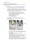
To install the Coulochem III Analyst driver on your PC, perform the following steps.
1. Ensure that the Coulochem III detector is off or disconnected. (If on, the detector
could interfere with the installation of the USB driver.)
2. Close all running software applications. Then insert the Coulochem III Analyst Driver
CD into your CD-ROM drive. The installation program should start automatically
(unless CD auto-run is disabled on the PC). If it does not start automatically, click
Start > Run, then type drive:\setup (where drive is the drive letter of your CD-ROM
drive, e.g. D:\setup), then click OK. The InstallShield Wizard should appear, as in
Figure 2.1 below.
Figure 2.1. Installation Introductory Page.
3. Click the Next button. This will display the License Agreement.
6
Coulochem® III Analyst Driver – Version 1.0
User’s Manual
System Requirements and Installation
4. Read the License Agreement and print a copy, if desired, by clicking the Print button.
If you agree to the terms of the License Agreement, select the I Accept... button and
click Next.
5. When the Ready to Install dialog appears, click Install to start the driver installation
process.
6. The installer will add the Coulochem III Analyst driver files to the folder C:\Program
Files\ESA Biosciences\Coulochem III Analyst Driver. It will then automatically
install the USB driver for the Coulochem III detector.
7. When finished, click the Finish button.
8. Remove the installation CD and store it in a safe place.
After installation, an icon will appear on the desktop for starting the Coulochem III driver
(with or without first starting Analyst), and a menu entry will appear in the Start > All
Programs menu under ESA Biosciences.
2.4
Hardware Configuration
The Coulochem III detector can be customized to accommodate a wide variety of analytical
needs. The ‘Coulochem® III for MS’ is the standard configuration for use with ABI’s mass
spectrometers. This platform allows the use of the Coulochem III module to control
electrochemical (EC) cells with fixed (DC) or dynamic (pulsed) potential waveforms. Cells
can be used as reactors in series upstream of the MS ion source and/or as detectors in parallel
(via flow split) with MS. Serial EC/LC-MS configurations allow MS study of EC reactions
and products while parallel EC with MS provides complementary and highly sensitive
detection of redox active species. Some examples of these applications are provided in
Chapter 7 of this manual. For additional detail please contact your ESA Biosciences
representative.
The Coulochem® III for MS (ESA P/N 70-6045A) includes the Controller with DC and Pulse
Mode capability, the Model 5021A EC cell (reactor cell with ca 16µL swept volume) Model
5030 EC cell (reactor cell with ca 3µL swept volume), cables and Ground Decoupling Kit.
Cells and optional accessories include:
Model 5021A Conditioning (Reactor) Cell...........................ESA P/N 70-6068
Model 5030 Low Volume Reactor Cell ................................ESA P/N 70-6069
Model 5010A Dual Analytical Cell....................................... ESA P/N 70-5560
Model 5040 Analytical Cell with Au Target.........................ESA P/N 55-0185
Adjustable Analytical Flow Splitter ......................................ESA P/N 70-6337
Thermally Controlled Cell Organizer Module ...................... ESA P/N 70-5499TA
Coulochem® III Analyst Driver – Version 1.0
User’s Manual
7
Chapter 2
To ensure proper grounding, it is essential that a Ground Decoupler Kit (ESA P/N 70-5971)
be used for connections between the mass spectrometer and the electrochemical cell(s) and
modules.
2.5
Connecting the Communications Cables
The Coulochem III detector can be connected to the PC by either an RS232 serial cable or a
USB cable. (USB is preferred, and a USB connection is required in order to perform
firmware updates – see Appendix A.)
If using a serial cable, connect one end of the cable to the RS232 Remote port on the
Coulochem III detector (Figure 2.2) and the other on an available COM port on the PC.
If using a USB cable, connect the small end of the cable to the USB Remote port on the
Coulochem III detector (Figure 2.2) and the wide end to an available USB port on the PC.
8
Coulochem® III Analyst Driver – Version 1.0
User’s Manual
System Requirements and Installation
Figure 2.2. Coulochem® III Back Panel.
Coulochem® III Analyst Driver – Version 1.0
User’s Manual
9
Chapter 2
2.6
Verifying the System
To operate properly, the Analyst program must be able to locate and communicate with the
Coulochem III driver (companion software). Proper installation of both the Analyst program
(with any required hotfixes) and the Coulochem III driver is essential in order for this
communication to occur. (If necessary, check with your Applied Biosystems / MDS Sciex
representative to ensure that you have the required hotfixes.)
To verify the installation, perform the following steps:
1. Turn the Coulochem III detector on and allow ample time for it to complete its startup
routine.
2. Start the Analyst program. If required, enter a login name and password (required
when running in Mixed mode).
3. Ensure that the Analyst Navigation Bar is visible. (Select View > Navigation Bar if
not.)
4. Verify that the item Coulochem III Detector appears in the Companion Software
section at the bottom of the Navigation Bar.
5. Double-click on the Coulochem III Detector item in the Navigation Bar. This should
start the Coulochem III driver, which will display its introductory splash screen, as
shown in Figure 2.3 below. (If running Analyst in Mixed mode, it will be necessary to
log on again prior to seeing the splash screen.)
Figure 2.3. Coulochem III Driver Introductory “Splash” Screen.
10
Coulochem® III Analyst Driver – Version 1.0
User’s Manual
System Requirements and Installation
6. After a few seconds the main driver window will appear.
7. If the Coulochem III detector is connected to the PC using a USB cable, a message
box like the following may appear:
Figure 2.4. Coulochem III Driver Communications Warning.
If this occurs, click OK. The message appears because the initial default
configuration assumes that the detector is connected through the serial port. This
situation will be corrected during configuration of the driver in a later section.
8. Confirm that the term Logged onto Analyst appears, in a dark green background, in
the Acquisition section at the bottom of the driver window.
9. Confirm that the term Connected to CcIII appears, also in a dark green background.
If the term Not connected to CcIII appears (in a bright red background), check the
serial cable connection. (If connected through a USB port, ignore the warning; the
situation will be corrected in a later section.)
Coulochem® III Analyst Driver – Version 1.0
User’s Manual
11
3. Starting and Configuring the Driver
3.1
Overview
Prior to using the Coulochem III Analyst driver to collect data, the driver needs to be
configured to match the actual Coulochem III detector configuration (including the
connection port). The detector connections were considered in Chapter 2. In this chapter, we
will ensure that the Coulochem III Analyst driver is configured to match the detector
configuration.
This chapter discusses how to set up the initial configuration of the driver, including the port
connection and hardware (cell) options. Once configured, changes to the configuration
should seldom be needed.
3.2
Starting the Coulochem III Analyst Driver
1. Turn on the Coulochem III detector and allow ample time for it to complete its startup
routine.
2. Start the Analyst program. If required, enter a login name and password (required
when running in Mixed mode).
3. Ensure that the Navigation Bar is visible. (Select View > Navigation Bar if not.)
4. Double-click on the Coulochem III Detector item in the Navigation Bar. This should
start the Coulochem III Analyst driver, which will display its splash screen, as shown
in the previous chapter. (If running Analyst in Mixed mode, it will be necessary to log
on again prior to seeing the splash screen.)
5. After a few seconds the main driver window will appear.
6. If a message box like the one shown in Figure 2.4 above appears, click OK. It may be
possible to correct the problem in Section 3.3, but observe the warning note at the end
of this section.
As soon as successful connections are made with both the Analyst program and the
Coulochem III detector, and the Coulochem III detector has completed its self-test sequence,
the Status area at the bottom of the driver window displays the connection status states in
green, as in Figure 3.1.
Coulochem® III Analyst Driver - Version 1.0
User’s Manual
13
Chapter 3
Figure 3.1. Status Bar Showing Successful Connections.
During the self-test sequence, the Coulochem III connection status appears in a yellow field,
as in Figure 3.2.
Figure 3.2. Status Bar During Coulochem III Self-Test.
The appearance of either of the above status conditions indicates a successful connection with
the Analyst program and the Coulochem III. If either the Analyst or Coulochem III
connection fails for any reason, the failure is indicated by a red background, as in Figure 3.3.
Figure 3.3. Status Bar Indicating a Failed Coulochem III Connection.
WARNING: After the communications port has been properly configured, the
Communications Error message box (Figure 2.4) should no longer appear when
starting up the driver. If it should appear at a later time, the warning should not be
disregarded, since it indicates a possible problem with communications between the
detector and the PC. Note that the problem could be as simple as forgetting to turn on
the Coulochem III detector.
14
Coulochem® III Analyst Driver – Version 1.0
User’s Manual
Starting and Configuring the Driver
3.3
Accessing the Coulochem III Driver Window
The Coulochem III driver works alongside the Analyst program, so normally both
programs are open at the same time. This will often cause the driver window to be
“hidden” behind the Analyst program. There are many simple ways to make the
driver visible when this happens, including any of the following:
•
Click the ESA Coulochem III button on the Windows task bar at the bottom of
the display.
•
Double-click the Coulochem III Detector item in Analyst’s Navigation Bar.
(This will not open another instance of the driver.)
•
Press Alt-Tab from the keyboard and select the driver.
NOTE: Although the normal procedure is to start Analyst first and then start the
Coulochem III driver, it is possible to run the Coulochem III Analyst driver without
running Analyst first, by double-clicking the Coulochem III Analyst Driver icon on the
desktop or selecting Coulochem III Analyst Driver from the Start > All Programs
menu under ESA Biosciences. When the driver appears to be running without Analyst,
it is actually still connected to Analyst through a Windows service. This service
allows changes to be made to the driver configuration without having to start the
Analyst program. It is also possible to make changes to acquisition methods this way,
without having to open the Analyst program. It is not possible, however, to create new
methods without Analyst. All acquisition methods must be initiated in Analyst, as
explained in subsequent sections.
Coulochem® III Analyst Driver – Version 1.0
User’s Manual
15
Chapter 3
3.4
Configuring the Coulochem III Analyst Driver
The Coulochem III can be configured in either DC or pulsed mode. In DC mode, 1 or 2
channels can be utilized, along with an optional guard cell and thermal organizer. Operation
in pulsed mode uses a single channel and does not use the guard cell.
The driver must be configured to reflect actual hardware as well as experimental preferences
prior to use with the Analyst program for data acquisition.
1. From the driver menu, select Instrument > Coulochem III Configuration.
Figure 3.4. The Coulochem III Configuration Dialog
2. From the configuration dialog, Figure 3.4, select the appropriate options for each of
the following parameters:
•
CC III operating mode
Select either DC or Pulse mode.
•
Comm port
Select USB if connected to the Coulochem III through an available USB port.
If connected though a serial port, select either COM1, COM2, COM3 or
COM4, depending on which ports are available. (If unsure, start with COM1.
If this causes problems later, return to the configuration and try COM2, COM3
16
Coulochem® III Analyst Driver – Version 1.0
User’s Manual
Starting and Configuring the Driver
and COM4 in order.)
•
Event marker height
During the course of a data acquisition run, the user may specify that a marker
be placed in the acquisition data to designate a particular event, such as an
autozero. The event marker height is the height of this marker, designated as a
percent of the full scale data output range.
Select a value between -20% and +20% full scale.
•
Enable channel 2
Check this box if the Coulochem III detector has been fitted with a second
channel cell and you wish to use the cell in your next (first) acquisition. Most
applications that use an EC cell primarily as a reactor typically only require a
single channel (channel 1). Many applications of EC for detection and
quantitation use dual EC cells to obtain higher selectivity, for example through
oxidation-reduction or oxidative screening.
•
Enable guard channel
Check this box if the Coulochem III detector has been fitted with a guard cell
and you wish to use the guard channel in your next (first) acquisition. The
signal from the guard channel cannot be monitored using an ADC.
•
Enable thermal organizer
Check this box if the Coulochem III detector has been fitted with an optional
thermal organizer (ESA P/N 70-5499T) and you wish to display the thermal
organizer properties in the main driver window. (Activation of the organizer is
controlled in the main driver window.)
•
Enable event marker on autozero
Check this box if you would like to have the driver automatically create a
marker in the acquisition data whenever an autozero event occurs. The
autozero marker height is determined by the Event marker height set above.
•
Lock keypad
This box is normally checked, and is not accessible to the user.
The Set Defaults button can be clicked at any time to set all values to their hard
default values. (See Appendix B for a table of all user-accessible values, along with
default and range values.)
3. Click OK to accept the changes made to the configuration.
4. If a change was made to the Comm port value, ensure that the connection status in the
Acquisition section of the driver window now indicates Connected to CcIII on Port,
where Port is either USB or one of the COM ports. If the connection status appears as
Coulochem® III Analyst Driver – Version 1.0
User’s Manual
17
Chapter 3
Not connected to CcIII (in a bright red background), try one of the following to fix
the problem:
a. Ensure that the Coulochem III detector is on.
b. Ensure that the connection (USB or serial cable) is secure.
c. If using a serial connection, try another COM port in the configuration.
d. If using a serial connection, check the serial port settings on the Coulochem III
detector. To do this, perform the following steps:
i. Exit the Coulochem III Analyst driver by selecting File > Exit from the
menu.
ii. From the main menu of the Coulochem III detector (COULOCHEM
MAIN MENU visible on the display), press the SYSTEM button. This
should activate the SYSTEM SETUP MENU on the display. (If the
SYSTEM button is inactive, it may be necessary to turn the Coulochem
III off and back on again. Then repeat and continue from this step.)
iii. Press the NEXT button.
iv. Press the DEFAULT button.
v. Press the NEXT button.
NOTE: When properly configured, both the Logged onto Analyst and Connected to
CcIII indicators should appear on a dark green background, as described in Section
3.2. An improper connection is indicated by a bright red background.
18
Coulochem® III Analyst Driver – Version 1.0
User’s Manual
4. Creating and Modifying Acquisition Methods
4.1
Overview
An acquisition method consists of a set of parameters that describe the detector environment
in which data acquisition is to occur as well as the duration and sequence of events that are to
occur during the acquisition.
In a setting where both mass spectrometry and electrochemical detection are utilized,
acquisition method parameters must be assembled for both instrument environments. The
Analyst program manages all aspects of the mass spectrometry while the Coulochem III
driver manages all aspects of electrochemical detection, receiving status updates on the
execution of the mass spectrometer (MS), for synchronization. Despite this separation of
instrument environments, all acquisition parameters are consolidated into a single method file
(an Analyst *.dam), which is managed entirely by the Analyst program. This necessitates a
somewhat strict protocol by which the MS and electrochemical detection method details are to
be entered in a new method file, specifically:
a. Create a Hardware Configuration Profile (a “profile”) in Analyst. This profile
specifies all of the MS instrument parameters as well as basic properties of
connected devices like pumps and autosamplers. The profile also provides the
ability to specify that a Coulochem III detector is connected to the system.
Once configured, the same profile can be used over and over again, until it is
necessary to change basic instrument or device parameters. Multiple profiles can
be created, stored and reused, but only one profile may be active at a time.
b. Build an acquisition method within Analyst. This method initially will contain all
parameters to be used for MS control. The method is saved as a *.dam file by
Analyst.
c. Build a Coulochem III method. This method details the parameters to be used, and
activities to be run, on the Coulochem III detector. Coulochem III method
parameters can only be set within the Coulochem III Analyst driver.
d. Attach the Coulochem III method data to the Analyst method data file. Without
this step, the Coulochem III method would not be known by Analyst or available
to it. Attaching the Coulochem III method data to the Analyst *.dam file also
allows the parameter data to be managed under the control of the Analyst
program’s secure filing system.
Other configuration and method data, such as data for pumps and autosamplers, may be
communicated to Analyst through their respective drivers.
Coulochem® III Analyst Driver - Version 1.0
User’s Manual
19
Chapter 4
The sections below describe each of these steps in detail.
4.2
Creating and Activating a Profile
A profile specifies all mass spectrometer instrument parameters as well as basic properties of
connected devices like pumps, autosamplers, the Coulochem III detector and the A/D
converter.
The instrument profile for a typical metabolite identification study (see section 7) may include
a binary pump, autosampler, Coulochem III module and mass spectrometer. The Coulochem
III module may be used to control a pre-column EC reactor cell. For a given parent
compound, a series of injections is made, each with the cell set at a different applied potential.
EC oxidation or reduction products are then separated chromatographically and characterized
by mass spectrometry. The signal (current or charge) produced from the EC reactions may
also be simultaneously monitored using the ADC.
The basic steps for creating a profile that includes the Coulochem III detector and ADC are:
1. From Analyst, double-click the Hardware Configuration item in the Navigation Bar.
This opens Analyst’s Hardware Configuration Editor dialog.
2. Click the New Profile button, to open Analyst’s Create New Hardware Profile dialog.
3. Click the Add Device button.
4. Add a Mass Spectrometer device to the profile, as well as any pumps, ovens,
autosamplers and other devices that you may require, by selecting from the Device
Type drop list, then the Devices list and clicking OK. Refer to the Analyst program
manual for specific details on adding and setting up these devices. (The Coulochem
III module and ADC card additions are described in the next steps.)
5. Add the Coulochem III detector to the profile by clicking the Add Device button and
then selecting Software Application from the Device Type drop list. Highlight
Software Application from the Devices list and click OK. Figure 4.1 shows the Create
New Hardware Profile dialog for a simple profile just after adding the Coulochem III
driver as a Software Application.
20
Coulochem® III Analyst Driver – Version 1.0
User’s Manual
Creating and Modifying Acquisition Methods
Figure 4.1. Hardware Profile with Coulochem III Detector (Unconfigured)
6. Highlight the Software Application text, then click the Setup Device button and select
(highlight) Coulochem III Detector from the list of software applications in the
Software Application Settings dialog, Figure 4.2.
Figure 4.2. Software Applications Settings Dialog
Coulochem® III Analyst Driver – Version 1.0
User’s Manual
21
Chapter 4
7. Enter “CcIII”, or something similar, as the alias name, then click OK.
8. If an ADC connection has been implemented between the Coulochem III detector and
the PC, for collecting analog data from the Coulochem III detector, click the Add
Device button again to configure the ADC. If an analog connection will not be used,
continue at step 12 below.
9. Select A/D Converter from the Device Type drop list, then highlight A/D Converter
NIDAQ16 (or the particular ADC to be used), and click OK.
10. Highlight the A/D Converter chosen and click Setup Device. The correct settings for
the NIDAQ16 converter (NI 6032E PCI board) are illustrated in Figure 4.3 below for a
2-channel system. Note that each channel is configured separately. If 2 channels are
to be used, be sure to configure the second channel by selecting 2 as the Channel No.
and ensuring that the Channel Connected checkbox is checked for channel 2 (as in the
figure).
Note that for the NI 6032E PCI board, the Polarity / Range must be set to -10.0V to
+10.0V, and the Mode must be set to Referenced Single Ended.
Figure 4.3. ADC Configuration for the NI 6032E PCI Board
22
Coulochem® III Analyst Driver – Version 1.0
User’s Manual
Creating and Modifying Acquisition Methods
11. Click OK to close the Create New Hardware Profile dialog.
12. Enter a profile name in the Profile Name edit box, then click OK.
A profile’s instrument components can be examined by clicking the small [+] box to
the left of the profile name. Figure 4.4 shows the profile “MS with CcIII and ADC”
configured with the MS, Coulochem III Detector and A/D Converter. Once
configured, the same profile can be used over and over again, and profiles may be
modified to accommodate changes in devices connected within a profile. Multiple
profiles can be created, stored and reused, but only one profile may be active at a time.
13. Prior to building or using an acquisition method, a profile must be activated. Activate
the newly created profile by selecting (highlighting) it and then clicking the Activate
Profile button.
Since the Coulochem III device is a part of the new profile, the Coulochem III driver
should open soon after clicking the Activate Profile button. Allow the driver to finish
its splash screen sequence, then click its Minimize button (upper right corner) to
minimize its window to the Windows task bar.
14. Click Close to close the Hardware Configuration Editor dialog.
Figure 4.4. Example Configuration “MS with CcIII and ADC”.
Coulochem® III Analyst Driver – Version 1.0
User’s Manual
23
Chapter 4
4.3
Building an Analyst Acquisition Method
All acquisition methods must be initiated in Analyst. Begin building a method by doubleclicking the Build Acquisition Method item in the Acquire section of the Analyst Navigation
Bar.
Set the parameters for the mass spectrometer according to the requirements of the
experimental run. (Refer to the Analyst and MS manuals).
To set the A/D Converter properties, click on the A/D Converter item in the left panel.
1. In the Analog/Digital Converter Properties tab, adjust the Rate value to the desired
sampling rate.
2. Ensure that a check appears in the checkbox corresponding to each channel for which
you wish to have Analyst collect and store data.
3. Adjust the Interpreted Value @ Full Scale and Interpreted Unit values for each
channel as required.
Note that clicking on the Coulochem III Detector item in the left panel displays an empty
Software Application Properties tab. After the Coulochem III method has been configured, in
the next section, this tab will display all Coulochem III method-related values.
Save and close the method, using a file name that will make it easy to remember the method’s
purpose or content.
4.4
Building a Coulochem III Method and Attaching to Analyst
Display the Coulochem III driver by clicking the ESA Coulochem III task button on the
Windows task bar. If the driver does not appear on the task bar, restart it by double-clicking
Coulochem III Detector in Analyst’s Navigation Bar.
The Coulochem III driver window displays its method parameters in three different tabs:
Detector Setup, Pre-Run, and Timed Events. In addition, if a thermal organizer is attached to
the Coulochem III module and indicated in the configuration setup, controls for activating the
organizer and for setting its setpoint temperature are displayed on the window.
Note: All of the method parameters and their ranges and default values are tabulated in
Appendix B.
4.4.1
Detector Setup Tab
The Detector Setup tab displays the parameter settings for either DC mode or
Pulse mode (depending on the configuration set up earlier).
24
Coulochem® III Analyst Driver – Version 1.0
User’s Manual
Creating and Modifying Acquisition Methods
4.4.1.1
DC Mode
DC mode method parameters are illustrated in Figure 4.5.
Figure 4.5. Detector Tab Parameters for DC Mode
Note that when channel 2 and/or the guard channel are enabled, the same fields
are used to enter parameters for channel 1, channel 2 and the guard cell. Use
the drop list control to indicate which channel’s parameters you wish to view
or modify.
Channel Drop List. Select either Channel 1, Channel 2 or Guard. Selections
allowed depend on the system configuration parameters, so, for example,
Channel 2 will not appear in the list if the checkbox Enable channel 2 was not
checked in the ESA Coulochem III Detector Configuration dialog (see section
3).
Coulochem® III Analyst Driver – Version 1.0
User’s Manual
25
Chapter 4
WARNING: Remember to set potentials, filter constants, etc. for all
channels in the configuration. Forgetting to set a channel’s parameters may
lead to unexpected experimental results.
Cell potential. Select the cell potential for the designated channel, in mV.
The “spin buttons” in this field change the potential 10 mV at a time. (The up
and down arrows on the keyboard have the same effect.) For more exacting
control, enter the required potential from the keyboard. The range is -2000 to
+2000 mV. The choice of potentials depends on the oxidation-reduction
properties of the compounds being investigated. Typically, the choice of
potentials is made after running a series of stepped potentials over multiple
injections of the compounds of interest.
Filter time constant. Values of 0.2, 0.5, 1.0, 2.0, 5.0 and 10.0 sec are
allowed. The value of this parameter is only relevant when monitoring the EC
signal using the ADC. A small filter constant provides the least smoothing of
data. Optimizing this parameter is primarily relevant when using the EC cell
for highly sensitive detection. In that case, select the lowest filter constant
needed to improve the signal-to-noise ratio. Default is 5.0 sec.
Full scale gain range. The full scale gain range runs from 10 pA to 1 mA in
steps of 1, 2, 5, 10, 20, 50, 100, 200 and 500. The value of this parameter is
primarily relevant when monitoring the EC signal using the ADC. Set this
value above the highest current expected for the analyte of interest over the
course of the experiment. Default is 100 µA.
Signal output voltage. This is the maximum analog signal the detector will
output to a strip chart recorder or ADC unit. Select from values of -1 V, -100
mV, +100 mV and +1 V. Default is +1 V.
% Baseline offset. This is the ratio by which a flat signal baseline is offset on
a chart recorder or ADC unit, expressed as a % of full scale. Offset values
from -50% to +50% are allowed. Default is 0 %.
Post Run Clean Cell. Check this box if the selected channel is to be used in
post-run cleaning. A clean cell period is used to help desorb products that may
have a high affinity for the electrodes, and is typically used with potentials that
are higher than those normally used in detection. Clean cell is normally used
only when indicated, typically when the signal for a certain compound begins
to decline from its normally observed value after repetitive injections.
26
Coulochem® III Analyst Driver – Version 1.0
User’s Manual
Creating and Modifying Acquisition Methods
Cell potential (clean cell). Select the post-run potential for cleaning the
selected channel (electrode). The range for clean cell potentials is -2000 mV
to +2000 mV. When using a clean cell cycle, use a potential that is higher than
that normally used for the compound(s) being detected.
Clean time. Clean times may be selected from a minimum of 1 sec to a
maximum of 120 sec. Typical clean cell times are 30 – 60 sec.
Post clean cell delay. This is the amount of time given to allow the detector to
stabilize after the clean cell period. Delay times may be selected in the range
0.1 to 10.0 min. Typical clean cell delay time is 0.5 min. or less when using
the cell only as a reactor. A longer delay, typically 2 minutes, is required when
using EC for sensitive detection and depends largely on the gain range setting.
4.4.1.2
Pulse Mode
Pulse mode method parameters are illustrated in Figure 4.6. Pulse mode is
typically used for EC detection of specific analyte classes, such as
carbohydrates, that are not readily measured using DC techniques. In this case
the parameter settings are typically based on literature values (e.g., ESA
Biosciences’ Application Notes). This mode however provides a great deal of
flexibility to experiment with dynamic waveforms to effect reactions not
readily observed with DC for MS study.
Coulochem® III Analyst Driver – Version 1.0
User’s Manual
27
Chapter 4
Figure 4.6. Detector Tab Parameters for Pulse Mode
Acquisition Delay. Select a value from 50 to 495 msec (default 300). The
value of this parameter is primarily relevant when monitoring the EC signal
using the ADC.
28
Coulochem® III Analyst Driver – Version 1.0
User’s Manual
Creating and Modifying Acquisition Methods
E1 – E4 Potentials. Values from -2000 to +2000 mV are allowed. Default
values for potentials E1 thru E4 are:
E1:
200 mV
E2:
-1000 mV
E3:
600 mV
E4:
-100 mV
E1 – E4 Pulse Widths. The pulse width for E1 must be at least 5 msec greater
than the acquisition delay. Maximum value for all pulse widths is 1000 msec.
Minimum and default values are:
E1: AD+5 msec minimum
500 msec default
E2:
4 msec minimum
10 msec default
E3:
0 msec minimum
1 msec default
E4:
0 msec minimum
10 msec default
Full scale gain range. The full scale gain range runs from 10 pC to 10 mC in
steps of 1, 2, 5, 10, 20, 50, 100, 200 and 500. Set this value above the highest
signal expected over the course of the experiment.
Signal output voltage. Select from values of -1 V, -100 mV, +100 mV
and +1 V. Default is +1 V.
% Baseline offset. Offset values from -50% to +50% are allowed. Default
is 0 %.
Filter setting. Select None, Low, Med or High. Use the lowest filter needed
to reduce output noise. Default is None.
Coulochem® III Analyst Driver – Version 1.0
User’s Manual
29
Chapter 4
4.4.2
Pre-Run Tab
Just prior to actual data collection, Analyst provides a “pre-run” period during
which any instrument attached to the active profile may delay the start of data
acquisition. The Coulochem III driver (see Figure 4.7) provides the user with
three options for the pre-run interval. These include a simple pre-equilibration
period of up to 2 hrs, autozero prior to run, and waiting to reach the thermal
organizer setpoint temperature:
Figure 4.7. Pre-Run Tab Parameters (DC and Pulse Modes).
Pre-equilibrate for n minutes. Checking this option and setting a non-zero
equilibration time tells the Analyst program to delay data acquisition by at least
the period indicated. (Other options may extend it.) This allows the Coulochem
III detector to stabilize any new cell potentials between runs. A pre-equilibration
period of a few minutes is normally used when transitioning from high to low (or
low to high) potentials between samples (and methods). Larger differences in
potentials would indicate longer stabilization times.
30
Coulochem® III Analyst Driver – Version 1.0
User’s Manual
Creating and Modifying Acquisition Methods
Autozero prior to run. If this option is checked, the Coulochem III detector will
perform an autozero at the end of the pre-run interval. The pre-run interval will
automatically be extended as necessary in order to ensure that at least 15 seconds
expire for proper detector stabilization after the autozero.
Wait for Thermal Organizer. Checking this option ensures that the pre-run
period will not end until the thermal organizer temperature has reached within 2°
C of its setpoint. If Autozero prior to run is also checked, the autozero is
performed only after the thermal organizer has reached its setpoint.
Pre-run options are available for both DC and Pulse mode operation of the
Coulochem III detector.
Coulochem® III Analyst Driver – Version 1.0
User’s Manual
31
Chapter 4
4.4.3
Timed Events Tab
The Timed Events tab (Figure 4.8) lets the user specify various actions to be
performed during data acquisition. These actions include:
- adjusting the gain range
- adjusting the cell potentials (DC mode only)
- performing an autozero
- turning cells off
- placing an event marker in the data
Events are entered by selection from a drop list. Channel value is selected by
drop list, but may be grayed out if not applicable to the line’s event. Value entries
may be made by drop list or manually, depending on the event, and may be
grayed out if not applicable to the line’s event.
Figure 4.8. The Timed Events Tab with Event Examples
The total duration of Coulochem III data acquisition is determined by the greater
of the time of the last event (after sorting) and the MS acquisition time.
32
Coulochem® III Analyst Driver – Version 1.0
User’s Manual
Creating and Modifying Acquisition Methods
Each timed event consists of a time point and an event type. Some events may
also include an event channel as well as an event value.
Timed events are tabulated in the Timed Events grid. The default grid has no
events. To add an event, simply click in the cell that reads “Select to add
event...”, then choose an event from the drop list. Click in either adjacent cell to
“activate” the event. Edit the event’s time, in minutes, and, if a cell has either a
channel option or an associated value, select or edit the appropriate channel or
value cell. Cells with no expected entries are displayed in light gray.
Depending on personal preference, timed events can be entered using primarily
the mouse or the keyboard. When primarily using the keyboard, each time the
Tab key is pressed the focus moves to the next cell in the row. Pressing the Tab
key at the end of a row advances the focus to the Time column of the next row.
(Shift Tab reverses the flow.) When a cell has the focus, its contents can be
edited by using the up and down arrow for drop lists (Event, Channel and Gain
Range Value) or by editing directly (Time and Potential Value).
Time. Specifies the time of the event in minutes from the beginning of EC data
acquisition.
Event. Specifies the event to occur at the specified time.
Channel. Specifies the channel or channels on which the event is to apply. The
channel is irrelevant in Pulse mode. In DC mode, the channel can be specified for
the Gain Range, Potential and Event Mark events only.
Value. Specifies the value for the event. This applies only to the Gain Range and
Potential (DC mode only) events.
The following events can be designated:
Gain Range. This event changes the gain range to a new value, selected from the
drop list in the Value field, at the specified time into the run.
Auto Zero. This event implements an autozero at the specified time. An
autozero event must not occur at the end of the timed events. Furthermore, the
next event following the autozero event must not occur before 15 sec (0.25 min)
have elapsed since the autozero. These conditions are checked prior to attaching
the method properties to an Analyst file; a warning is provided if the conditions
are not met.
Cells Off. This event turns the cells off at the specified time. Once turned off,
cells cannot be turned back on by another timed event. (There is no Cells On
Coulochem® III Analyst Driver – Version 1.0
User’s Manual
33
Chapter 4
event.) However, cells can be turned back on manually by clicking the Cells On
button on the driver window.
Event Mark. This event sets a marker spike in the raw analog data at the
specified time into the run. In DC mode, the event can indicate which channel or
channels are to receive the marker. Marker height depends on the value provided
in the Coulochem III Configuration dialog (Section 3.4).
Potential. This DC-mode-only event changes the cell potential to a new value
given by the Value field, in mV, on the channel selected from the list box in the
Channel field, at the specified time into the run.
Click the Sort Events button to sort the events by time.
Click the Clear All button to clear all events from the Timed Events grid.
4.4.4
Thermal Organizer Controls
If the thermal organizer option is included in the Coulochem III system (and this
has been indicated in the Coulochem III Configuration dialog - Section 3.4),
controls for the thermal organizer will appear in the driver window (Figure 4.9).
Figure 4.9. The Thermal Organizer Group Controls
To activate the thermal organizer, check the Activate checkbox. When active, the
group of controls in the Thermal Organizer group box indicate actual and setpoint
temperatures in Celsius. The display is updated about every second. The
following describes each of the controls in the Thermal Organizer group:
Activate. Check this checkbox to activate the thermal organizer. Uncheck to
disengage the organizer. When disengaged, the organizer has no effect on
temperature control.
Actual Temp. This is the actual temperature in the thermal organizer chamber,
updated every second.
34
Coulochem® III Analyst Driver – Version 1.0
User’s Manual
Creating and Modifying Acquisition Methods
Current ST. This is the current active setpoint temperature stored within the
Coulochem III detector.
Set Temp. This edit field allows the user to change the Coulochem III’s stored
setpoint temperature. The Apply Temp button (see below) must be clicked in
order for the new Set Temp to be applied to the Coulochem III.
Apply Temp button. Click this button to change the Coulochem III’s stored
setpoint temperature to the value provided in the Set Temp field.
ST±2 Indicator lamp. This indicator turns green whenever the thermal
organizer’s actual temperature is within 2° C of its setpoint temperature.
4.4.5
Attaching the Method to an Analyst File
The Coulochem III constituents of the data acquisition method consist of all of the
parameters found on the Detector Setup tab, Pre-Run tab, Timed Events tab and
Thermal Organizer control group (if active). In order for these parameters to
become part of an Analyst method, they must be attached to an existing Analyst
acquisition method (*.dam) file.
To attach the Coulochem III method parameters, select File > Attach Method to
Analyst File... and select the Analyst acquisition file from among the *.dam files
listed. Click Save to attach and save the modified method. Note that an error
message will appear if you enter a new file name and click the Save button. The
Coulochem III method data must be saved to an existing Analyst acquisition
method.
Remember that without this step, the Coulochem III method data will not be
known by Analyst and will not be available to it.
4.4.6
Viewing the Coulochem III Method from within Analyst
Once the Coulochem III method data has been attached to an Analyst acquisition
method file, its parameters can be viewed from within Analyst. To view the
method, follow these steps:
1. Select and open the *.dam file in Analyst by selecting File > Open from the
Analyst menu, then selecting Acquisition Method (*.dam) from the drop list.
Select the file from the file list.
2. Click on Coulochem III Detector in the left panel of the Acquisition method
display. The Software Application Properties tab will display all of the
Coulochem III configuration data, pre-run conditions, thermal organizer
Coulochem® III Analyst Driver – Version 1.0
User’s Manual
35
Chapter 4
settings, mode parameters (DC or Pulse) and timed events for the method, as
illustrated in Figure 4.10.
To print the Coulochem III method data, right click anywhere in the tabulated
data and select Print from the context menu.
Figure 4.10. Analyst Program Showing Coulochem III Method Properties
4.5
Modifying an Attached Coulochem III Method
Once Coulochem III method data has been attached to an Analyst acquisition, it is possible to
modify the file data at any time. However method data that is in use in an actively acquiring
method cannot be modified.
To modify the Coulochem III method data that is attached to an Analyst file, select File >
Read Method from Analyst File from the Coulochem III driver menu, select the *.dam file
to be read, and click Open. This loads the method data into the driver window. The data can
then be modified as required. To save and reattach the data to an Analyst file, select File >
Attach Method to Analyst File... and select the Analyst acquisition file from among the
*.dam files listed. (It does not have to be the same file that was previously read.) Click Save
to attach and save the modified method data.
36
Coulochem® III Analyst Driver – Version 1.0
User’s Manual
Creating and Modifying Acquisition Methods
4.6
Modifying a Coulochem III Method While Acquiring Data
During active data acquisition the parameters of the actively running Coulochem III method
are loaded and displayed in the Analyst driver window and tabs. All fields are disabled in
order to prevent modification during a run. However, it is still possible to modify any
acquisition method during acquisition; a separate menu item and dialog are available for this
purpose.
To modify an existing attached method, select File > Edit Method from Analyst File from
the driver menu, select the file from the list and click Open. The method editing dialog
shown in Figure 4.11 will appear.
Figure 4.11. Method Editing Dialog.
This dialog has all of the same tabs as the main driver window, and editing is done in exactly
the same way as described in the sections above. To view or modify the configuration
parameters, select Coulochem III Configuration from the dialog’s Instrument menu. To
view or modify the Thermal Organizer parameters, select Thermal Organizer from the
dialog’s Instrument menu. In either case, a new sub-dialog will appear with all of the same
parameters as are found on the main driver interface. Remember to click the OK button when
closing the sub-dialog if you wish to save any changes made.
Coulochem® III Analyst Driver – Version 1.0
User’s Manual
37
Chapter 4
To attach the modified method data to the original Analyst file, click the Attach Changes to
Analyst button at the bottom of the editing dialog, or select File > Attach Changes to
Analyst File from the dialog’s menu.
Click the Cancel button if you decide not to change the original Analyst file.
WARNING. It is possible to modify the actively running acquisition method using this
dialog. However, when a sample is submitted to the sample queue, the then-current values of
the method parameters are stored in the queue’s sample parameters. Modifying a method
after samples have been added to the queue will not change the method parameters in the
existing queue samples from their original values, but samples added to the queue after the
method change will show the changes. Further, once the acquisition method parameters have
been loaded into the Coulochem III driver, just prior to the run for each sample, they remain
fixed throughout the run.
Keep this in mind when modifying Coulochem III method parameters. The modifications
will not affect samples already submitted to the queue, but they will affect new samples added
to the queue after the modification.
38
Coulochem® III Analyst Driver – Version 1.0
User’s Manual
5. Basic Coulochem III Driver Functions
5.1
Overview
The Coulochem III driver provides some basic detector functionality even when not actively
involved in data acquisition, such as the ability to apply settings to the Coulochem III
detector, perform an autozero, and turn cells on and off. This section examines these
independent functions, and begins with a discussion of the behavior of the driver during
startup and shutdown as it connects or disconnects with the Coulochem III detector.
5.2
Startup and Shutdown Sequences
5.2.1
Startup Sequence
Immediately after confirming the connections to both Analyst and the Coulochem
III detector, the Coulochem III driver recalls the last configuration it was in (DC
vs. Pulse mode, Enable channel 2, Enable guard cell, etc.) prior to shutdown, and
attempts to reestablish the same configuration. It then disables most of the keys
on the Coulochem III keypad, sends default method parameters to the Coulochem
III for the recalled mode and starts the Coulochem III in DC or Pulse mode.
After completing this sequence, the Coulochem III detector display panel will
show the current default mode settings.
This startup behavior occurs whether the Coulochem III driver is initiated from
the icon on the desktop, from the Companion Software items in Analyst or as the
result of activating an Analyst hardware profile.
5.2.2
Shutdown Sequence
After the user attempts to close the Coulochem III driver (by File > Exit or other
standard means), the driver stops the Coulochem III detector, unlocks the keypad
and restores the detector display to the main menu. It then stores the current
configuration data before finally closing.
Coulochem® III Analyst Driver - Version 1.0
User’s Manual
39
Chapter 5
5.3
Direct Coulochem III Detector Control
The main display surface of the Coulochem III driver provides a set of 5 buttons for directly
controlling the Coulochem III detector. These buttons are shown in Figure 5.1 below.
Figure 5.1. The Driver’s Detector Control Buttons and Indicators
Auto Zero. Click this button to autozero the detector. “Autozeroing” adjusts the gain to
produce a zero signal. In a 2-channel setup in DC mode, the autozero is applied across both
channels. The Auto Zero button is disabled during the pre-run, acquisition and post-run
(clean cell) phases of a run.
In DC mode, post-autozero stabilization can last up to 15 seconds (or more), while in Pulse
mode it is nearly instantaneous. During autozero the indicator next to the Auto Zero button
lights green.
Apply Gain. Click this button in DC mode to apply the current full scale gain range to each
enabled channel. The Apply Gain button is disabled in Pulse mode. The button is also
disabled during the pre-run, acquisition and post-run (clean cell) phases of a run.
Cells On/Off. Click either of these buttons to turn the cells on or off. When on, the indicator
next to the Cells On button lights green. These buttons always remain enabled, even during a
run.
Apply Settings. Clicking this button sends all of the current settings (DC or pulse) to the
Coulochem III detector and resets the detector to activate the new values. The Apply Settings
button is disabled during the pre-run, acquisition and post-run (clean cell) phases of a run.
5.4
Thermal Organizer Control
If the system is equipped with a thermal organizer, and the organizer is enabled, the Apply
Temp button (see Figure 4.10) is used to set the setpoint temperature (from the Set Temp
field) in the Coulochem III. The Apply Temp button is disabled during the pre-run,
acquisition and post-run (clean cell) phases of a run.
40
Coulochem® III Analyst Driver – Version 1.0
User’s Manual
Basic Coulochem III Driver Functions
The ST±2 indicator turns green whenever the thermal organizer’s actual temperature is within
2º C of its setpoint temperature.
For more on the thermal organizer, see Section 4.4.4.
Coulochem® III Analyst Driver – Version 1.0
User’s Manual
41
6. Acquiring Data with the Coulochem III Driver
6.1
Overview
The basic steps in running samples with the Coulochem III driver are:
1. Start Analyst
2. Activate a hardware profile. See Section 4 for more on hardware profiles involving
the Coulochem III detector.
Note: Once a profile has been activated it is normally not necessary to deactivate the
profile when closing the Analyst program (unless other components require
deactivation; the Coulochem III driver does not). If Analyst is closed without
deactivating the active profile, restarting Analyst will automatically restart the
Coulochem III driver.
3. Build acquisition methods as appropriate for the samples. The same method may be
used for all samples, or different methods may be used for different samples.
Remember to attach Coulochem III parameters to the method. See Section 4 for more
on building acquisition methods.
4. Build an acquisition batch.
5. Submit batch samples to the batch queue.
6. Run the samples in the queue.
Figure 6.1 illustrates a simple 5-sample batch using method “DC 2ch with Guard”.
Figure 6.1. A Simple Batch with 5 Samples
Coulochem® III Analyst Driver - Version 1.0
User’s Manual
43
Chapter 6
Instructions for building acquisition batches and running the queue samples can be found in
the Analyst manual and are no different when involving the Coulochem III detector and
driver. Refer to the manual for details.
6.2
Viewing the Progress of a Coulochem III Acquisition
As the Analyst program manages the acquisition of each sample in a batch, it dispatches
information at various times to each of the instruments or drivers in the active hardware
profile, including the Coulochem III driver. Just prior to the start of the pre-run phase,
Analyst provides the Coulochem III driver with all of the Coulochem III detector-specific
configuration and method data for the sample that is about to be run. Analyst obtains this data
from the acquisition method file (and its attached Coulochem III method data). The
Coulochem III then updates its interface with these values.
As the run begins its pre-run phase, the Coulochem III driver automatically switches to the
Pre-Run tab and begins to display the pre-run time in the Acquisition status region at the
bottom of the driver window (Figure 6.2). The Pre-run phase is also designated in yellow in
the Status indicator in this region.
Figure 6.2. Acquisition Status Bar During Pre-Run Phase.
The duration of the pre-run phase depends on the parameters activated and assigned in the
Pre-Run tab. After the pre-equilibration time designated in the Pre-equilibrate for field, the
driver will extend the pre-run phase by as much time as needed for the thermal organizer to
reach within 2° C of its setpoint (if activated and checked). If checked, the autozero is
performed only after the Pre-equilibrate for time has elapsed and the setpoint has been
approached. An additional 15 seconds is added post-autozero to ensure adequate stabilization
from the autozero event.
The acquisition phase begins immediately after the pre-run phase. The Coulochem III driver
automatically switches to the Timed Events tab and begins to display the run time in the
Acquisition status region at the bottom of the driver window (Figure 6.3). The acquisition
phase is designated in green in the Status indicator.
As the run progresses, and as each timed event is processed in the timed events grid, the lastexecuted event is highlighted.
44
Coulochem® III Analyst Driver – Version 1.0
User’s Manual
Acquiring Data with the Coulochem III Driver
Note that during the entire run the Cells On and Cells Off buttons are the only controls that
are accessible to the user. All other user input is disabled.
Figure 6.3. Driver Display During the Acquisition Phase of a Run
After the last timed event has been processed, the post-run phase begins. This phase involves
cleaning the cells, so the driver switches to the Detector Setup tab, where the clean cell
properties are displayed. The phase lasts for as long as the longest combination of Clean time
and Post clean cell delay for either channel or the guard cell that is enabled.
During the post-run phase the Coulochem III driver displays the post run time in the
Acquisition status region at the bottom of the driver window (Figure 6.4). The post-run phase
is designated in blue in the Status indicator.
Coulochem® III Analyst Driver – Version 1.0
User’s Manual
45
Chapter 6
Figure 6.4. Acquisition Status Bar During Post-Run (Clean Cell) Phase.
After all 3 phases of the run have been completed, the driver reverts to the idle state and
displays idle time in the Status indicator, in preparation for the next sample. The 3-phase
acquisition repeats for each remaining sample in the Analyst queue, until all samples have
been run.
6.3
Aborting a Batch from the Driver Program
A batch can be aborted from within the Coulochem III driver during any phase of the
acquisition. To stop the batch, select Instrument > Abort Batch from the driver menu.
Aborting a batch causes the driver to shift immediately to the post-run (clean cell) phase of
the currently executing run. The driver also sends a signal to Analyst to stop any further
execution of the batch.
6.4
Viewing the Coulochem III Electrochemical Data Profile and
Method Properties
During the acquisition phase of a run, the analog electrochemical data signal is sent to the
A/D Converter box, converted to a digital stream of data and fed into the Analyst program for
storage inside an Analyst
To view the electrochemical profile(s), select File > Open Data File from the Analyst main
menu. Then select the data file from the files listed, and then the sample name, and click OK.
Analyst opens the file and displays the total ion chromatogram (TIC) data by default. To
view the electrochemical profile(s), right-click in the TIC plot and select Show ADC Data
from the context menu. Select A/D Converter – Channel 1 and click OK, then repeat to
display channel 2 if using 2 channels. Figure 6.5 shows an example of electrochemical data
profiles for 2 channels.
46
Coulochem® III Analyst Driver – Version 1.0
User’s Manual
Acquiring Data with the Coulochem III Driver
Figure 6.5. Example Electrochemical Data Profiles in Analyst (Bottom 2 Panels)
Coulochem® III Analyst Driver – Version 1.0
User’s Manual
47
Chapter 6
To view the method properties associated with the file, highlight any plot and select Explore
> Show > Show File Information (or press Ctrl-I on the keyboard). Analyst displays a
considerable amount of property data for the file, including a section for Software Application
Properties. This section displays the Coulochem III method properties, as shown in Figure
6.6.
Figure 6.6. Coulochem III Method Properties Displayed in a Data File’s
Software Application Properties
48
Coulochem® III Analyst Driver – Version 1.0
User’s Manual
7. Application Examples
7.1
Overview
This chapter provides examples of the use of the Coulochem III detector to control
electrochemical (EC) cells with fixed (DC) or dynamic (pulsed) potential waveforms. Cells
can be used as reactors in series upstream of the MS ion source and/or as detectors in parallel
(via flow split) with MS. Common applications are for on-line derivatization (e.g., to assist
MS ionization, for mass tagging and protein cleavage) and to study the susceptibility of
compounds to oxidation (or reduction), the nature of products and short-lived intermediates,
and the associated reaction pathways. These applications are of interest for generating and
characterizing products that often correspond to biological metabolites, degradants or reactive
species of interest. The use of EC in parallel with MS provides complementary, orthogonal,
detection with high sensitivity and selectivity for redox active species. Typical applications
are DC detection of antioxidants and markers of oxidative stress and pulsed detection of
carbohydrates.
Each example tabulates the conditions for the liquid chromatography (LC) setup, Coulochem
III (EC) setup and mass spectrometer (MS) setup.
Coulochem® III Analyst Driver - Version 1.0
User’s Manual
49
Chapter 7
7.2
Assisted Ionization – DC Mode
Many neutral or non-polar compounds do not ionize very readily. However, oxidative
derivatives of electrochemically active compounds may be more readily ionizable. In this
example, the Coulochem III is used to control an EC reactor cell placed in series, upstream,
with an electrospray ion (ESI) source. The EC cell is used to convert solution-phase neutral
species of butylated hydroxyanisole (BHA) to those that are more readily ionized for ESI-MS
analysis.
LC Conditions
•
•
•
Mobile phase: 50% MeOH, 20 mM NH4Acetate
Flow rate: 0.1 ml/min
Injection: 10 µl BHA, 20 µg/ml
EC Conditions
•
•
•
•
•
•
•
•
ESA Model 5021A Conditioning (Reactor) Cell
Ground Decoupling Kit (ESA P/N 70-5971) connected between EC cell and MS.
Cell potential: 600 mV
Filter time constant: 0.5 sec
Full scale gain range: 10 µA
Signal output voltage: +1V
Baseline offset: 0 %
Pre-equilibration: 2 min, autozero prior to run
MS Setup
•
•
50
Electrospray: positive ion mode
Q1 Scan 100 to 500 m/z
Coulochem® III Analyst Driver – Version 1.0
User’s Manual
Application Examples
Results
120
120
EC Potential -200mV
80
60
EC Potential 600mV
Max intensity 10057
100
m/z
181.5
100
OH
80
Max intensity 417280
m/z
179.5
O
60
C(CH3)3
40
20
OCH3
20
0
100
C(CH3)3
40
OCH3
0
200
300
400
500
m/z
100
200
300
m/z
400
500
Figure 7.1. Results of Assisted Ionization Run with BHA
The left panel in Figure 7.1 above shows an injection of 200ng of BHA with the EC cell at 200mV, a potential at which no EC reaction is expected. The spectrum is very low intensity
with little evidence of protonated BHA (m/z 181.5). The right panel shows a similar injection
with the EC cell potential at 600mV. There is an intense peak at m/z 179.5 representing an
oxidized species derived from BHA. This is a simple demonstration of the ability of EC to
convert a solution-phase neutral species to a more readily ionized species. The ability to
automate control of the EC cell potential and change potential within a run (via timeline)
and/or between runs (via different methods in an Analyst batch) provides a significant amount
of experimental flexibility.
7.3
Metabolite Identification – DC Mode
Typical applications of serial EC-MS involve on-line generation and analysis of EC products
using LC-MS conditions that are typical of metabolic studies (e.g., in vitro microsomal
analysis). Serial EC/LC-MS can thus be used with ‘neat’ parent compound solutions for
preliminary optimization of LC and MS conditions for subsequent metabolite analysis in
biological samples. By using identical conditions, EC data may then be used as input to
automated metabolite identification software (i.e., Analyst® Metabolite ID) to aid in finding
metabolites present in more complex biological matrices. Furthermore, when the data from
an EC-generated product corresponds to that of a biological metabolite, the EC technique may
then be viewed as a selective and rapid synthetic route to small quantities of this metabolite.
This can then be used to facilitate structural elucidation or, more generally, to produce
additional chemical entities. The following example shows the utility of the Coulochem III
Analyst Driver for automated analysis of tamoxifen with an EC reactor cell controlled at
different oxidative potentials for each injection.
Coulochem® III Analyst Driver – Version 1.0
User’s Manual
51
Chapter 7
LC Conditions
• Column: Shiseido C18 MG 3µm 4.6 mm ID x 75 mm
• Mobile phase gradient:
o A: 1% ACN, 20 mM NH4Acetate
o B: 80% ACN, 20 mM NH4Acetate
Flow
Time
%B
(ml/min)
0.00
10.00
12.00
12.01
15.00
•
•
•
20
100
100
20
20
1
1
1
1
1
Flow rate: 1 ml/min
Injection: 10 µl Tamoxifen, 20 µg/ml (200 ng)
After diode array, flow splitter (ESA P/N 70-6228) adjusted to allow 200 µl into
the MS.
EC Conditions
•
•
•
•
•
•
•
•
ESA Model 5021A Conditioning (Reactor) Cell
Ground Decoupling Kit (ESA P/N 70-5971) connected between EC cell and MS.
Cell potential: 500 mV, repeat at 1000 mV
Filter time constant: 0.5 sec
Full scale gain range: 10 µA
Signal output voltage: +1V
Baseline offset: 0 %
Pre-equilibration: 2 min, autozero prior to run
MS Setup
• Electrospray: positive ion mode
• Enhanced MS Scan 100 to 500 m/z
52
Coulochem® III Analyst Driver – Version 1.0
User’s Manual
Application Examples
Results
Figure 7.2 shows results for 200 ng Tamoxifen with the EC cell at a potential of 500 mV.
Two forms of Tamoxifen are primarily observed, at m/z 358.8 (A) and 372.8 (B).
4e+6
EC Potential 500mV
TIC
3e+6
2e+6
cps
1e+6
0
120
100
80
60
40
20
0
A
A
0
2
4
6
8 10
Time (min)
XIC m/z 358.8
O
NH
CH3
CH3
100
B
200
300
400
120
100
80
60
40
20
0
B
12
14
XIC m/z 372.8
O
N
CH3
CH3
CH3
100
m/z
200
300
400
m/z
Figure 7.2. Tamoxifen at a Cell Potential of 500 mV
Coulochem® III Analyst Driver – Version 1.0
User’s Manual
53
Chapter 7
Oxidation at 1000 mV produces 3 additional oxidation products (Figure 7.3), with peaks at
m/z 299.8 (D), 356.8 (A) and 388.8 (B).
1.6e+6
1.4e+6
EC Potential 1000mV
1.2e+6
TIC ESI+
1.0e+6
8.0e+5
6.0e+5
4.0e+5
2.0e+5
0.0
0
2
4
cps
E
C
A
D
B
6
8
10
12
14
Time (min)
120
120
100
A
XIC m/z 356.8
120
B
100
80
XIC m/z 388.8
60
N
CH3
N
CH3
40
CH3
20
0
100
200
300
400
0
100
200
CH3
CH3
300
0
100
400
200
m/z
120
N
H
20
OH
m/z
100
40
CH3
20
O
60
CH3
40
XIC m/z 358.8
80
O
O
60
C
100
80
300
400
m/z
120
D
XIC m/z 299.8
100
80
OH
60
XIC m/z 372.8
60
O
N
CH3
CH3
40
40
CH3
CH3
20
20
0
100
E
80
200
300
m/z
400
0
100
200
300
400
m/z
Figure 7.3. Tamoxifen at a Cell Potential of 1000 mV
This example demonstrates that the EC oxidation products for a given compound often
coincide with metabolites observed in biological assays. The Coulochem III Analyst driver
allowed for automated analysis of tamoxifen using various EC cell potential. The simplicity
and speed of on-line EC-LC-MS often provides an effective means of characterizing some of
the many unknown metabolites encountered in multivariate profiling studies.
54
Coulochem® III Analyst Driver – Version 1.0
User’s Manual
Application Examples
7.4
Carbohydrate Detection – Pulsed Mode
The following example illustrates the use of the Coulochem III Analyst Driver for automated
analysis in which a dynamic (pulsed) potential EC waveform is used. In this case the pulsed
waveform is used with a gold working electrode EC cell. A typical application is for sensitive
EC detection of carbohydrate species in parallel with MS. Serial EC-MS with pulsed
waveforms is also of interest in effecting reactions that may not be observed with fixed DC
conditions.
LC Conditions
• Column: ESA Carbohydrate RCX-10
• Mobile phase: 100 mM ammonium hydroxide
• Flow rate: 1.5 ml/min
EC Setup
• Analytical cell: ESA 5040 Amperometric cell (gold working electrode)
• Potentials and pulse widths:
Potential
Pulse width
(mV)
(msec)
•
•
•
•
•
•
E1
200
E2
-1000
E3
600
E4
-100
Acquisition delay: 300 msec
Full scale gain range: 1 µC
Signal output voltage: +1V
Baseline offset: 0 %
Filter setting: None
Cleaning:
500
10
1
10
E2
T2
T1
E1
Acquisition
Delay
Measurement
Coulochem® III Analyst Driver – Version 1.0
User’s Manual
E3
T3
Conditioning
55
Chapter 7
Results
Figure 7.4 shows the oxidation profile for a simple mixture of carbohydrates (20 pmoles
total).
Figure 7.4. EC Detection of a Simple Carbohydrate Mixture
56
Coulochem® III Analyst Driver – Version 1.0
User’s Manual
Appendix A: Updating the Coulochem III Firmware
A.1
Overview
The Coulochem III detector is shipped with the latest version of its firmware – the internal
software that is responsible for its operation. The firmware version is shown on the
Coulochem III front panel display while the detector is running its self-test sequence just after
powering on.
Improvements to the software logic may make it advantageous to update the detector’s
firmware. ESA provides a utility for updating the firmware logic on your Coulochem III.
The utility updates only the executable firmware. It does not update system variables such as
the serial number and baud rate, and it will not affect your stored methods.
This chapter describes how to update the firmware using the Corona-Coulochem Firmware
Update Utility CD (ESA P/N 70-6968), which may be obtained from your ESA
representative. (The CD uses the same basic utility for updating both the Coulochem III and
the Corona CAD instruments.) The steps below detail both the installation and use of the
utility.
A.2
Preparation and Installation of the Utility
1. Ensure that the Coulochem III detector is turned off.
2. The Corona-Coulochem Firmware Update Utility cannot operate over the serial port; it
must use a USB port. If the Coulochem III has already been connected and operated
successfully through the USB port, the required USB driver has already been installed.
If not, it may be necessary to install the USB driver. The utility will detect either
condition for you.
3. If not already connected through the USB port, a USB cable will be required (standard
type A to B). ESA P/N 70-5713 is a 3 meter cable of this type. Connect the small end
of the cable to the USB Remote port on the Coulochem III and the wide end to an
available USB port on the PC.
4. Close all running software applications. Then insert the Corona-Coulochem Update
Utility CD into your CD-ROM drive. The installation program should start
automatically (unless CD auto-run is disabled on the PC). If it does not start
automatically, click Start > Run, then type drive:\setup (where drive is the drive letter
of your CD-ROM drive, e.g. D:\setup), then click OK.
5. When the installation program starts, click the Install button. This will automatically
install the Corona-Coulochem Firmware Update Utility program files in the
Coulochem® III Analyst Driver - Version 1.0
User’s Manual
57
Appendix A
C:\Program Files\ESA Biosciences folder. It will also ensure that the ESA USB driver
is properly installed.
6. When finished, click the Finish button.
7. Remove the installation CD and store it in a safe place.
A.3
Updating the Firmware with the Update Utility
1. Ensure that the USB cable is properly connected, as described in the previous section.
2. Turn on the Coulochem III and allow it to complete its power-up tests.
3. Start the update utility by selecting Start > All Programs > Corona-Coulochem
Firmware Update Utility > Corona-Coulochem Firmware Update Utility from the
Windows Start menu. When operating on the Coulochem III, the update utility will
appear as in Figure A-1 below.
Figure A-1. Firmware Update Utility for Coulochem III
58
Coulochem® III Analyst Driver – Version 1.0
User’s Manual
Updating the Coulochem III Firmware
When properly connected through the USB cable, the message “Connected” appears
near the top of the utility window, and the utility shows both the serial number and the
current firmware (software) version number.
4. Click the Update button. When the Open dialog appears, navigate to the Program
Files folder (normally on Drive C), then to the ESA Biosciences subfolder and finally
to the Corona-Coulochem Firmware Update Utility folder (i.e., to the folder
C:\Program Files\ESA Biosciences\Corona-Coulochem Firmware Update Utility).
5. Select the file coulochem #.##.run, where #.## is the version number of the new
firmware update (for example, “coulochem 3.07.run”). If more than one such file is
found, select the one with the highest (latest) version number. Then click Open.
6. The update utility will replace all of the existing firmware with the version on the
update CD. The process should take no more than a few minutes. When finished, the
message “Download complete Coulochem III rebooting” will appear near the top of
the window and the Coulochem III will reboot automatically.
7. Click Exit to close the update utility.
Coulochem® III Analyst Driver – Version 1.0
User’s Manual
59
Appendix B: Parameter Ranges and Default Values
B.1
Configuration and Method Parameter Ranges and Defaults
Table B1 below lists all configuration and method parameters, along with each parameter’s
range, units and default value.
Table B1. Parameter Ranges and Default Values
Parameter
Range
System Configuration
Mode
Communications port
Enable channel 2
Enable guard channel
Enable thermal organizer
Enable event marker on AZ
Event marker height
Lock keypad
DC or Pulse
COM1...COM4, USB
yes or no
yes or no
yes or no
yes or no
-20 to +20
yes or no
DC Mode
Ch 1 Potential
Ch 1 Filter Constant
Ch 1 Gain Range
Ch 1 Output Voltage
Ch 1 Baseline Offset
Ch 2 Potential
Ch 2 Filter Constant
Ch 2 Gain Range
-2000 to +2000
0.2, 0.5, 1.0, 2.0, 5.0, 10.0
10 pA to 1 mA in steps of 1, 2,
5, 10, 20, 50, 100, 200, 500
-1.0, -0.1, +0.1 or +1.0
-50 to +50
Units
%
Default
DC
COM1
no
no
no
no
5%
yes
mV
sec
--
50 mV
5.0 sec
100 µA
V
%
+1 V
0%
mV
sec
--
50 mV
5.0 sec
100 µA
Ch 2 Output Voltage
Ch 2 Baseline Offset
-2000 to +2000
0.2, 0.5, 1.0, 2.0, 5.0, 10.0
10 pA to 1 mA in steps of 1, 2,
5, 10, 20, 50, 100, 200, 500
-1.0, -0.1, +0.1 or +1.0
-50 to +50
V
%
+1 V
0%
Guard Potential
-2000 to +2000
mV
0 mV
Post-Run
Ch 1 Enable Clean Cell
Ch 1 Clean Cell Potential
Ch 1 Clean Cell Duration
Ch 2 Enable Clean Cell
Ch 2 Clean Cell Potential
yes or no
-2000 to +2000
1.0 to 120.0
yes or no
-2000 to +2000
Coulochem® III Analyst Driver - Version 1.0
User’s Manual
mV
sec
mV
no
0 mV
1 sec
no
0 mV
61
Ch 2 Clean Cell Duration
Guard Enable Clean Cell
Guard Clean Cell Potential
Guard Clean Cell Duration
Post Clean Cell Delay *
1.0 to 120.0
yes or no
-2000 to +2000
1.00 to 120.0
0.00 to 10.00,
but ≥ longest Duration above
sec
mV
sec
min
1 sec
no
0 mV
1 sec
1.00
* Provides post clean cell delay values for both channels and guard.
Pulse Mode
Acquisition Delay (AD)
E1 Potential
E1 Pulse Width
E2 Potential
E2 Pulse Width
E3 Potential
E3 Pulse Width
E4 Potential
E4 Pulse Width
Full Scale Gain Range
Signal Output Voltage
Baseline Offset
Filter Constant
50 to 495
-2000 to +2000
AD+5 to 1000
-2000 to +2000
4 to 1000
-2000 to +2000
0 to 1000
-2000 to +2000
0 to 1000
10 pC to 10 mC in steps of 1, 2,
5, 10, 20, 50, 100, 200, 500
-1 or +1
-50 to +50
none, low, medium, high
Pre-run Parameters
Pre-equilibrate
Pre-equilibrate time
Auto zero prior to run
Wait for thermal organizer
yes or no
0.00 to 120.00
yes or no
yes or no
Thermal Organizer Parameters
Activate
yes or no
Set Temp
15 to 60
62
msec
mV
msec
mV
msec
mV
msec
mV
msec
--
300 msec
200 mV
500 msec
-1000 mV
10 msec
600 mV
1 msec
-100 mV
10 msec
1 µC
V
%
+1 V
0%
none
min
C
no
1.00
no
no
yes
32
Coulochem® III Analyst Driver – Version 1.0
User’s Manual