1
TENMAR5
LU)UFC LED Light Meter
TM-201 L / TM-209/TM-209N
/TM-209M
User's manual
TENMARS ELECTRON ICS CO.,LTD
T€N
1.
CONTENTS
. Description................... ............1
2. Safety Precaution
....................
3. Preface
...............2
4. features..
.............3
5. Specifications.............. .............4
6. Operation
............ 6
'l
1
7.
8.
Measures light from visible luminaries equipped with
white light LED, fluorescent, metal halide, high-pressure
sodium and incandescent sources.
2.
lnstrument Description of TM-201L............. 13
lnstrument Description of ffM-20e/209N/200H,1y........... 14
10.
Attention..
........ 156
11. Recommended Levels of lllumination .........17
12.Battery
13. End of
Replacement
|ife............
............. 18
................... 18
Safety Precaution
Be extremely careful for the following
conditions while measuri
Luminous intensity measurement 6H,l-zost zOOtUZosvl 12
9.
Description
a
a
Do noi operate the meter under the environment
with explosive gas (material), combustible gas
(material) steam or filled with dust.
in order to avoid reading incorrect data, please
replace the battery immediately when the symbol
"ffi"
on the LCD'
"PP""tt
to avoid the damage caused by
ln order
contamination or static electricity, do not touch the
circuit board before you take any adequate action'
Operating Environment: lndoors use. This
instrument has been designed for being used in an
environment of pollution degree 2.
Operation Altitude: UP to 2000M.
Operating Temperature & Humidity: 5'C - 40.C'
0%- 80%RH.
Storage Temperature & Humidity: -10"C - 60'C '
Oo/"-
7lokR{.
EMC: EN61326-1(2006), IEC 61000-4-2(2008' IEC
61000-4-3(2006) + (2007).
EN-1
TEN
T€N
3.
4.
Preface
The flux of light received in a unit area of a certain side
being shown is popularly known as illumination. The
measuring unit in both United Kingdom and America is
known as footcandles light, but in Europe it is also
a
o
o
known as meter candlelight.
a
Its abbreviated form is written as 1 Fc=1 Lm/ft, similarly,
one-meter candlelight is the illumination of light that falls
on a side which is one meter away from a one meter
candlelight and exactly intersecting the light. lt is also
called Lux i,e. the flux of light being received in each sq.
meter is called the illumination of one lumen.
a
a
O
o
1 FC=10.764 LUX, 1 LUX=0.09290 FC,
therefore,Nbr. of foot (meter) candlelight =
Nbr. of Lumen
Nbr. of Lumen=Nbr. of foot (or meter)x area
EN.2
Overload lndication: LCD screen will show "OL" on
the upper left-hand corner.
Low battery lndication" I:+1".
Sampling Rate: 2.5 times per second for digital
display.
One foofcandles light is the illumination of light that
falls on one side which is one foot away from a one
foot-candlelight and exactly intersecting with the light.
Area(sq. foot or sq. meter)
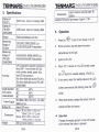
Features
a
a
o
a
a
Spectial response close to CIE luminous spectral
efficiency.
Cosine Angular corrected.
According to JIS C 1609:1993 and CNS 51'19
general A class SPecifications
Measuring lights source: LED white light and all
visible light.
Measuring intensities of illumination in Lux or
footcandles.
Many applications include: Warehouses, factories,
office bu ildi ngs, restaurants, schools, library'
hospitals, photographic, many video, parking
garages, museums, art galleries, stadiums, building
security.
Data hold.
Maximum hold.(TM-201 L)
Maximum/Average/Minimum Hold.(TM-209/
209N/209M)
Zero adjustment.
Auto power off and disable function. (TM-209/
209N/209M)
Auto ranging. (TM-209/ 209N/209M)
EN-3
TEN
5.
TEN
.l-usert
Accessones
L .,
manual, carrying case. 9V
Specifications
Display of
TM-2011
Display of
(TM-209/
209N/209tvt\
Sensor
Measuring
Range of
TM-201L
Measuflng
Range of
(TM-209/
209N/209M)
2000 count, maximum display 1999
4000 couni, maximum display 3999
Silicon photodiode and filter
200,2000, 20000,200000 Lux
20,200,2000,20000 Footcandles
Angle deviation
from cosine
red LED light spectrum)
8% other visible light source(TM-2O1L)
6% other visible light source(TM-209/
209N/209M)
30
l!2oh
60
11]6o/"
characteristics
80"
Power Supply
Batterv life
Dimensions
/r/eioht
6.
1.
2.
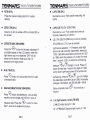
Operation
Press tfre
"@"
button to turn power on or off'
Remove sensor cap and place ihe sensor
perpendicular to the light
40,400,4000, 40000,400000 Lux
40,400,4000,40000 Footcandles
13% (Calibrated to standard incandescent
lamp 2856" K and corrected LED day
while in white, amber, green, blue,
Accuracy
Length of wring for light sensor: Approx' 1.5M
3.
4.
9V NEDA 1604, tEC 6F22, JtS 006P
battery x 1oc
About 200 hours
Meter: 38 (H) x 55(W) x 130(L) mm
1 .s(H)x 2.2(W) x 5,1 (L) inch
Sensor: 25(H) x 55(W) x 80(L) mm
9.8H)x 2.2(W) x 3.1(L) inch
250 o (include batterv)
EN-4
When "OL" is shown on the LCD screen, press
the
5.
r\
e/button
for useable reading. (TM-2011).
lf you want to keep the reading value on the LCD
/<G\
screen permanently after testing, press the
"
"
!25o/o
Select LUX or FC.
"(iy'"
button.
6.
When done testing, replace the sensor cover to
protect the filter and sensor'
.
Data Hold
Freezes the reading present on the LCD screen
at the moment the button is pressed.
EN-5
TEN
T€N
o
.
o
R(TM-2011)
LXFC(TM-201L)
Press the manual ranging button for usable
reading.
llluminance Lux or Foot candle measuring unit
button.
ZERO (TM-2011)
LX/FC/CD(TM-209/ 209N/209M)
Adjust to 0, ADJ to enable LCD to indicate 000 on
the screen.
llluminance Lux or Foot candle and luminous
intensity measuring unit button.
L.S. (TM-209)(TM-2O9N only L9 can be revised)
zERO(TM -209/ 209N/209M)
(TM-209M only L7-19 can be revised)
Light source selection 1 - 9 features, each light
source can set correction parameters, default as
1.000. Calibration parameters can be set to 0 001
to 1.999, when the pressure L.S. button for more
than 1 second, LCD L.S. belowthe LN flashing,
"@"
Press the
SrUon for the zero adjustment if
any digits appear on the LCD screen, when the
light sensor cap is not attached "CAP" will be
shown on the screen. Make sure that it is
attached to the light sensor.
pressure Qor. S"nunge L'1 to Lg Press L-S
button for less than 1 second, the digits of 1'000
on the lower riqht-hand corner of the screen will
M-H (TM-2011)
Q"r@.
Press KO button to Lockup data maximal value
of measure data.
You can change
be ftashing, orlrrrr"
the calibration parameters as to 0.995, the display
chanqes immediately, set 350.0x0.996 = 348 6'
MAXAVG/Mt
Setup complete press
second.
N
(TM-209/ 209N/209M)
r/'\
\{J
Press
button simultaneously Lockup data
maximum and average and minimum value of
"V)'
measure data. Press the
button for more
than 1 seconds to disable this feature.
EN-6
L.S. (light
LI
tLED
6-")
"V
" for more than
1
source) factor:(TM'209)
white daY light : 0.99.
L2-L9 )Default Standard light source A: 1'00'
EN-7
TEN
.
source) factor:(TM-209N)
L.S. (light
L0)
L1
Standard light source A : 1.00.
tLED
white day light : 0.990.
L2t NEON BLUE light : 1.286.
L3t NEON GREEN light : 1.167.
L4t NEON PINK light: 0.760.
Lst NEON PURPLE light: 0.804.
L6t NEON RED light : 0.671.
L7t NEON YELLOW light: 0.840.
L8t NEON WHITE light: 0.870.
L9) Standard light source A : 1.00.
L.S. (light
source) factor:(TM-209M)
L0lStandard light source A : 1.00.
L1
tLED
RED light : 0.5'16.
L3tLED AMBER(YELLOW) light : 0.815.
L4tLED
L5tLED
L6tLED
.
Disable Auto Power Off (TM-209/ 209N/209M)
@
button for
When the power is on, press ftre
more than 1 second, to cancel or recovery
automatically shutdown. Automatic shutdown
" shows on the screen.
feature is enabled lf "
9
MEM(MOMORY) (TM-209/ 209N/209M)
ppsss @button for one second to store the data,
the LCD screen will display M and NO.01-NO.99.
When the AVG shows on the right hand corner of
/G;.,
the screen, press{lPbutton at this moment. LCD
will display AVG M and NO.01 - NO.99, and store
the AVG value at present moment.
white day light : 0.99.
L2tLED
L7-Lg)
Power off automatically after approx. 5 minutes
without using the meter.
GREEN light : 1.216.
BLUE light :1.475.
PURPLE light: 1.148.
Default Standard light source A: 1.00.
READ (READ MEMORY) (TM-209/ 209N/209M)
Pressure @ out,on for more than one second
to display ihe stored values, the LCD will display
M and NO. 01 - No.99, Or"r. Q or. S *"r,
to review all the stored values, for example,-NQ-L
tNO. 2 until NO. 99. lf the stored data is AVG
value, the screen will display AVG on the lower
@
Auto-Power Off (TM-209/ 209N/209M)
EN-8
button for more
left-hand corner. Press tne
one second to disable this feature.
EN-9
T€N
T€N
.
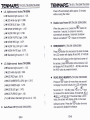
7.
Clear memory (TM-209/ 209N/209M)
when power is off, press
@ana @ortton,
together,then the screen will display "CL/'which
means the memorized data is erased.
Luminous lntensitY Measurement
(TM-209/ 209N/209M)
the'@"
2.
nrtton to turn power on or off.
Press
Remove sensor cap and place the sensor
perpendicular to the light.
3.
pr"., @
button for more than 1 second.
4.
,r"., Q
or.
1.
@
ornon to select ft(feet)or
m(meter).
5.
pr".. Q
6.
pru".
Q
button for less than 1 second.
0,o
set the distance between the
or
light center of lamp and measurement base level.
@
7.
o.
pr"r,
9.
Ornon for more 1 second to
Press
disable this feature.
button for less than 1 second.
Read the display.
the'@-
The luminous intensity is calculated using the
following formula:
Luminous intensity(cd)=illumination(Lx)x
distance(m2)
The preset maximum distance is 0.0'1
-
30'47 m
or 0.01 - 99.99 ft.
lf a single light source is used and is regarded as
a single-point light source, the luminous intensity
of the light source can be calculated and
displayed, by setting the distance from the light
source to the measuring Point.
EN-10
EN-,1
1
TM-20
8.
1.
2.
a
4.
5.
6.
7.
8.
1
L/TM-209N/TM-209M
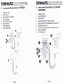
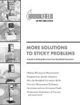
lnstrument Description of TM-201L
Display (LCD).
MAX HOLD.
Power Button: ON/OFF
Lux/Fc button
DATA HOLD buiton.
Range button.
Photo detector.
Zero Adjustment.
TEN
9.
1.
2.
J.
4.
5.
b.
7.
8.
9.
EN-12
lnstrument Description of (TM'209/
209N/209M)
Display (LCD).
Lux/Fc/CD button
MEM/READ.
MAXAVG/MlN and setuP upward'
Power ON/OFF and disable auto power off.
Real time auto zero.
DATA HOLD and Light source select (L.S.)
Setup downward.
Photo detector.
EN-13
TM-20
.
1
Lff M-209N/TM.2O9M
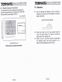
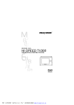
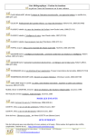
Relative Spectral (Sensitivity)
The deviation from the comparative standards for
luminosity is determined by JIS standard C 1609-1993'
Peak sensitivity wavelength: 550
Typ. Ta=23"C
nm
F
F
a
zuJ
a
ul
F
)tll
t
TEN
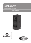
10. Attention
o
Set for referring the testing of source of light is
located at the right top end (0 degree) of the light
sensor ball plane.
Light Source 0 degree
100
I
80
10
60
50
40
30
20
lt\
€
10
0
r80 440 500 560 620 680 ?40
-V-
When the meter is not in use, please keep the
cap of the light sensor in its place to avoid the
photo diode from wearing out.
When it is not in use for a long time, please take
the batteries away. And avoid keeping it in
WAVELENGTH (nm)
*
place of high temperature and humidity.
CIE luminous sPectral luminous
EN-14
EN-15
a
T€N
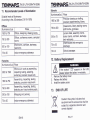
11. Recommended Levels of lllumination
Suitable levels of illuminance
(According to the JIS standard 29110-1979)
Schools
lllu minance(lux)
Place
Offices, conference rooms, computer
rooms
300 to 75
750 to 300
300 to 100
Workrooms, corridors, stairways,
restrooms
75 to 30
Precision drawing or drafting,
orecision experimenting, library
Classrooms, library reading rooms,
staff rooms, gymnasia
Lecture halls, assemblY rooms,
locker rooms, corridors, stairwaYs
and restrooms
Warehouses and emergencY
stairwavs
75 to 30
ndoor emergency stairways
1Olo2
School passages
Offices
Place
llluminance (lux)
1
500 to 750
1
500 to 300
750 to 200
Offices, desiqninq, drawing rooms
12. Battery RePlacement
Factories
llluminance (lux) Place
3000 to 1500
Where such work as assembling,
inspecting iesting, selecting,
extremelv orecision visual work
lf the symbol " l=ll" appears on the LCD'
the batterv
Removethe batterycover
Replace the battery.
lnstall the battery cover.
Assembling, inspecting, testing,
;electing, precision visual work
1.
2.
3.
750 to 300
Assembling, inspecting, testing,
selectinq and visual ordinary work
13.
100 to
r'Vrapplng and packing
1
500 to 750
150
75 to 30
lndoor emergency stairways
EN-16
END OF LIFE
X
I
i
Caution: this symbol indicates that
equipment and its accessories shall be
subject to a separate collection and
correct disposal
EN.17