1
CTX Mate Version 0.71
User’s Manual
Jack Devanney
Sisyphus Beach
Tavernier, Florida
2007
ii
c 2006, 2007 Jack Devanney
Copyright Permission is granted to copy, distribute and/or modify this document under
the terms of the Gnu Free Documentation License (GFDL), Version 1.2
or any later version published by the Free Software Foundation; with no
Invarient Sections, no Front-Cover Texts, and no Back-Cover Texts. A copy
of the GFDL is available at www.gnu.org.
CTX Mate is distributed under the Gnu Public Licence and can be
downloaded from www.c4tx.org. CTX Mate employs the immersed section
area integration algorithm initially developed by Herreshoff & Kerwin, Inc.
Halsey C. Herreshoff and Justin E. Kerwin have kindly allowed the Center
for Tankship Excellence to use this algorithm in the CTX Mate package.
However, CTX is solely responsible for the code that uses this algorithm.
Published by The CTX Press
212 Tarpon Street
Tavernier, FL 33070
Publishers’s Cataloging-in-Publication Data
Devanney, Jack
CTX mate user’s manual / Jack Devanney — Tavernier, Fla :
The CTX Press, 2006
p. : cm.
ISBN: 0-xxxxxxx-0-0
ISBN 13: yyy-0-xxxxxxx-0-z
1. Tankers – Design and Operations. 2. Tankers – Loading. 3.
Tankers – Spill reduction. I. Devanney, Jack. II. Title
VM455.D38 2005
387.2/45—dc22
Printed in the United States of America
10 09 08 07 06 • 5 4 3 2 1
2005938363
Contents
0 Testing Mate
0.1 Tolerances . . . . . . . . . . . . . . . . . . . . . . . . . . . . .
0.2 Allowables . . . . . . . . . . . . . . . . . . . . . . . . . . . . .
0.3 Test Conditions . . . . . . . . . . . . . . . . . . . . . . . . . .
1 Overview
1.1 Capabilities . . . . . .
1.2 Limitations and Bugs
1.3 Basic Methodology . .
1.4 About this Manual . .
.
.
.
.
.
.
.
.
.
.
.
.
.
.
.
.
.
.
.
.
.
.
.
.
.
.
.
.
.
.
.
.
.
.
.
.
.
.
.
.
.
.
.
.
.
.
.
.
.
.
.
.
.
.
.
.
.
.
.
.
.
.
.
.
.
.
.
.
.
.
.
.
.
.
.
.
.
.
.
.
.
.
.
.
1
1
2
4
.
.
.
.
7
7
12
14
15
2 Getting Started
2.1 From the desktop . . . . . . . . . .
2.2 From the command line . . . . . .
2.3 Mate Folders . . . . . . . . . . . .
2.4 Using Mate outside the Tanker File
. . . . .
. . . . .
. . . . .
System
.
.
.
.
.
.
.
.
.
.
.
.
.
.
.
.
.
.
.
.
.
.
.
.
.
.
.
.
.
.
.
.
.
.
.
.
.
.
.
.
17
17
19
22
24
3 The
3.1
3.2
3.3
3.4
3.5
3.6
3.7
.
.
.
.
.
.
.
.
.
.
.
.
.
.
.
.
.
.
.
.
.
.
.
.
.
.
.
.
.
.
.
.
.
.
.
.
.
.
.
.
.
.
.
.
.
.
.
.
.
.
.
.
.
.
.
.
.
.
.
.
.
.
.
.
.
.
.
.
.
.
.
.
.
.
.
.
.
25
25
30
38
41
50
53
55
Mainscreen
The Five Sections . . . .
The Tank Table . . . . .
The Summary . . . . . .
The Menubar . . . . . .
The Toolbar . . . . . . .
The Titlebar . . . . . .
Preserving Liquid Mass
.
.
.
.
.
.
.
.
.
.
.
.
.
.
.
.
.
.
.
.
.
.
.
.
.
.
.
.
.
.
.
.
.
.
.
.
.
.
.
.
.
.
.
.
.
.
.
.
.
.
.
.
.
.
.
.
.
.
.
.
.
.
.
.
.
.
.
.
.
.
4 Liquid Parcels
59
4.1 Editing Parcel Data . . . . . . . . . . . . . . . . . . . . . . . 59
iii
iv
CONTENTS
5 Point Loads
67
5.1 Editing Point Load Data . . . . . . . . . . . . . . . . . . . . . 67
6 The Load File
71
6.1 Saving a Loading Pattern . . . . . . . . . . . . . . . . . . . . 71
6.2 The Loadfile Format . . . . . . . . . . . . . . . . . . . . . . . 73
7 Saving Results
77
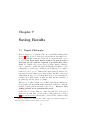
7.1 Report Philosophy . . . . . . . . . . . . . . . . . . . . . . . . 77
7.2 The EXPORT Menu . . . . . . . . . . . . . . . . . . . . . . . 78
8 Longitudinal Strength
83
8.1 Shear Force and Bending Moment Plots . . . . . . . . . . . . 83
8.2 The Strength Screen Command Bar . . . . . . . . . . . . . . 85
8.3 Longitudinal Strength Reports . . . . . . . . . . . . . . . . . 87
9 Stability
89
9.1 Metacentric Height . . . . . . . . . . . . . . . . . . . . . . . . 89
9.2 Righting Arm Curves . . . . . . . . . . . . . . . . . . . . . . . 90
10 Flooding
95
10.1 The Downflooding Report . . . . . . . . . . . . . . . . . . . . 95
11 IMO Regulation 25
99
11.1 Invoking the Reg 25 Function . . . . . . . . . . . . . . . . . . 99
11.2 Discussion of IMO Reg 25 . . . . . . . . . . . . . . . . . . . . 102
12 Sloshing Resonance
105
13 Hotspot Stress Analysis
107
13.1 Obigatory Warning . . . . . . . . . . . . . . . . . . . . . . . . 107
13.2 The Hotspot Screen . . . . . . . . . . . . . . . . . . . . . . . 108
14 Cargo Survey Reports
14.1 The Cargo Menu . . . . . . . . . . .
14.2 Rounding . . . . . . . . . . . . . . .
14.3 The OBQ Report . . . . . . . . . . .
14.4 The After-Discharge or ROB Report
14.5 The Ullage Survey Report . . . . . .
14.6 The Ullage-FAOP Report . . . . . .
14.7 The Ullage-EOP Report . . . . . . .
.
.
.
.
.
.
.
.
.
.
.
.
.
.
.
.
.
.
.
.
.
.
.
.
.
.
.
.
.
.
.
.
.
.
.
.
.
.
.
.
.
.
.
.
.
.
.
.
.
.
.
.
.
.
.
.
.
.
.
.
.
.
.
.
.
.
.
.
.
.
.
.
.
.
.
.
.
.
.
.
.
.
.
.
.
.
.
.
.
.
.
111
. 111
. 112
. 114
. 117
. 119
. 121
. 122
v
CONTENTS
15 Auto Mode
127
15.1 Entering Auto mode . . . . . . . . . . . . . . . . . . . . . . . 127
15.2 Auto Mode functions . . . . . . . . . . . . . . . . . . . . . . . 128
15.3 Gauging System Errors . . . . . . . . . . . . . . . . . . . . . 129
16 Damage Mode
16.1 The Damage Mode Mainscreen . . . . . . . . . . .
16.2 Checking vessel survivability . . . . . . . . . . . . .
16.3 Using Hotspot analysis to estimate loss of strength
16.4 Minimizing spillage whose source is uncertain . . .
16.5 Minimizing spillage whose location is known . . . .
16.6 Entering Damage Data . . . . . . . . . . . . . . . .
.
.
.
.
.
.
.
.
.
.
.
.
.
.
.
.
.
.
.
.
.
.
.
.
.
.
.
.
.
.
.
.
.
.
.
.
131
131
139
140
143
144
146
17 Stranding
151
17.1 Stranded Drafts and Heel Specified by User . . . . . . . . . . 151
17.2 Getting the Ship Off . . . . . . . . . . . . . . . . . . . . . . . 154
18 Non-GUI Use of Mate
157
18.1 Using Mate without a graphical interface . . . . . . . . . . . 157
18.2 The ctx mate cmd . . . . . . . . . . . . . . . . . . . . . . . . 158
18.3 Embedding ctx mate cmd within a bigger analysis . . . . . . 159
19 Volume Correction factors
161
19.1 Using the ctx vcf Command . . . . . . . . . . . . . . . . . . 161
20 Single Tank Analysis
165
20.1 The ctx tank Command . . . . . . . . . . . . . . . . . . . . . 165
21 Hull Hydrostatics
167
21.1 The ctx hull Command . . . . . . . . . . . . . . . . . . . . . 167
22 Errors
22.1 User Interface Problems . . .
22.2 Missing or Inconsistent Input
22.3 Convergence Failure . . . . .
22.4 Other Error . . . . . . . . . .
22.5 Bug Reports . . . . . . . . .
.
.
.
.
.
.
.
.
.
.
.
.
.
.
.
.
.
.
.
.
.
.
.
.
.
.
.
.
.
.
.
.
.
.
.
.
.
.
.
.
.
.
.
.
.
.
.
.
.
.
.
.
.
.
.
.
.
.
.
.
.
.
.
.
.
.
.
.
.
.
.
.
.
.
.
.
.
.
.
.
.
.
.
.
.
.
.
.
.
.
173
173
174
174
176
176
A Mate XML Reports
179
A.1 The Summary sub-report . . . . . . . . . . . . . . . . . . . . 179
A.2 The Options sub-report . . . . . . . . . . . . . . . . . . . . . 184
vi
CONTENTS
A.3
A.4
A.5
A.6
A.7
A.8
A.9
The
The
The
The
The
The
The
Header sub-report . . . .
Parcel sub-report . . . .
Tank sub-report . . . . .
Strength sub-report . . .
Stability sub-report . . .
Downflooding sub-report
IMO Reg 25 sub-report .
.
.
.
.
.
.
.
.
.
.
.
.
.
.
.
.
.
.
.
.
.
.
.
.
.
.
.
.
.
.
.
.
.
.
.
.
.
.
.
.
.
.
.
.
.
.
.
.
.
.
.
.
.
.
.
.
.
.
.
.
.
.
.
.
.
.
.
.
.
.
.
.
.
.
.
.
.
.
.
.
.
.
.
.
.
.
.
.
.
.
.
.
.
.
.
.
.
.
.
.
.
.
.
.
.
.
.
.
.
.
.
.
.
.
.
.
.
.
.
.
.
.
.
.
.
.
186
187
188
191
193
196
197
B Post-Processing
199
B.1 Post-processing with Perl . . . . . . . . . . . . . . . . . . . . 199
List of Tables
1
2
3
4
5
Deadweight & Lightweight
Tolerances . . . . . . . . .
Maximum Discrepancies .
Allowables . . . . . . . . .
Test Loading Patterns . .
for
. .
. .
. .
. .
.
.
.
.
.
1
2
2
3
4
4.1
Simplified Parcel Screen . . . . . . . . . . . . . . . . . . . . .
66
14.1
14.2
14.3
14.4
Sample OBQ Report . . . .
Sample ROB Report . . . .
Ullage Report, first page . .
Ullage Report, Second page
.
.
.
.
vii
DEMO ULCC
. . . . . . . . .
. . . . . . . . .
. . . . . . . . .
. . . . . . . . .
.
.
.
.
.
.
.
.
.
.
.
.
.
.
.
.
.
.
.
.
.
.
.
.
.
.
.
.
.
.
.
.
.
.
.
.
.
.
.
.
.
.
.
.
.
.
.
.
.
.
.
.
.
.
.
.
.
.
.
.
.
.
.
.
.
.
.
.
.
.
.
.
.
.
.
.
.
.
.
.
.
.
.
.
.
.
.
.
.
.
.
.
.
.
.
.
.
.
.
.
.
.
.
.
.
.
.
.
.
.
.
.
116
118
120
121
viii
LIST OF TABLES
List of Figures
3.1
Simplified Normal Mode Mainscreen . . . . . . . . . . . . . .
29
6.1
6.2
Sample Loadfile (top) . . . . . . . . . . . . . . . . . . . . . .
Sample Loadfile (bottom) . . . . . . . . . . . . . . . . . . . .
75
76
9.1
Sample Righting Arm Table . . . . . . . . . . . . . . . . . . .
94
11.1 Sample Reg25 Report . . . . . . . . . . . . . . . . . . . . . . 101
14.1 Excerpt from CTX style cargo survey report . . . . . . . . . . 126
A.1
A.2
A.3
A.4
Excerpt
Excerpt
Excerpt
Excerpt
from
from
from
from
Damage Mode Tank sub-report
Strength sub-report . . . . . . .
Stability sub-report . . . . . . .
Downflooding sub-report . . . .
ix
.
.
.
.
.
.
.
.
.
.
.
.
.
.
.
.
.
.
.
.
.
.
.
.
.
.
.
.
.
.
.
.
.
.
.
.
190
192
195
196
x
LIST OF FIGURES
Chapter 0
Vessel Data and Test
Conditions
0.1
Vessel Particulars & Tolerances
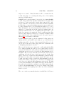
For ease in updating, all vessel specific information required by the Regulations to be included in a Loading Program Manual have been collected here
in Chapter 0. This data can be referred to as necessary. The manual proper
really starts with Chapter 1. Unless you are running a CTX Mate test condition or need to check vessel calculation tolerances, you may immediately
move on to Chapter 1. If you are running a Mate test, see Section 0.3.
CTX Mate uses the following summer deadweight and lightweight for
this ship. An unusual feature of Mate is that the input files describing
Table 1: Deadweight & Lightweight for DEMO ULCC
SUMMER DEADWEIGHT (metric tons)
LIGHTWEIGHT (metric tons)
LCG LIGHTWEIGHT (meters Fwd of Aft Perp.)
441561
67923
176.690
the ship which Mate actually uses are in human readable form, and can
be examined — but not changed — by any user. All these files are in
/X/uldh/DATA/MATE. Therefore, if you want to see what Mate is using, simply display the relevent file on you terminal or print it out. For example, for
the set of vessel particulars used by Mate, see /X/uldh/DATA/MATE/main.xml.
For this ship, internally Mate uses the weight and moment tolerances
1
2
CHAPTER 0. TESTING MATE
shown in Table 2. Since Mate uses a trial and error process in determining
Table 2: Weight and Moment Tolerances
Intact Fallback
Hull displacement (tons)
0.4
0.4
Longitudinal Moment (ton-meters)
1.3
1.3
Transverse Moment (ton-meters)
0.2
0.2
Tank volume (cubic-meters)
0.2
0.5
dDamaged
4.0
1300.0
21.0
12.5
the equilibrium drafts and heel, it is possible for the resulting solution to be
slightly different for the same loading pattern if the starting trial condition
is different. However, the discrepancies in the output should be no more
than those shown in Table 3.
Table 3: Maximum Discrepancies
INTACT DAMAGED
Hull displacement (tons)
(+/-)10
(+/-)400
Draft (meters)
(+/-)0.002
(+/-)0.020
Trim (meters)
(+/-)0.002
(+/-)0.040
Heel (degrees)
(+/-)0.002
(+/-)0.040
Shear Force (tons)
(+/-)50
(+/-)500
Bending Moment (ton-meters) (+/-)1500
(+/-)15000
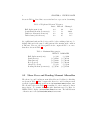
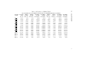
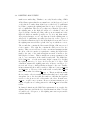
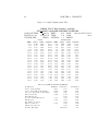
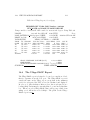
0.2
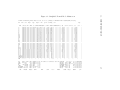
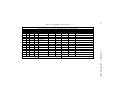
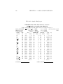
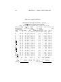
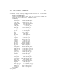
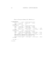
Shear Force and Bending Moment Allowables
The shear force and bending moment allowables used by Mate for this ship
are shown in Table 4. Mate computes the shear force and bending moment
at all the longitudinal stations shown in /X/uldh/DATA/MATE/frames.xml.
The allowables shown in Table 4 are translated to these stations by linear
interpolation. To examine the lightweight distribution used by Mate for
DEMO ULCC, display /X/uldh/DATA/MATE/ltwt.xml. The hull Moment
of Inertia curve is in /X/uldh/DATA/MATE/secmod.xml.
FRAME
NAME
FR 17
FR 29
FR 41
FR 59
FR 65
FR 67
FR 70
FR 75
FR 80
FR 85
FR 90
FR 95
FR100
FR105
FR110
FR115
FR129
MOMENT
IN PORT
SAGGING
-119634
-228932
-353781
-630641
-729528
-964853
-1304729
-1719830
-1884931
-1905314
-1905314
-1905314
-1654779
-1205312
-722962
-242908
-47917
0.2. ALLOWABLES
Table 4: Allowables for DEMO ULCC
ALLOWABLES IN TONS (SHEAR FORCE) AND TON-METERS(BENDING MOMENT)
FRAME
SHEAR
SHEAR
MOMENT MOMENT
SHEAR
SHEAR
MOMENT
FWD
AT SEA
AT SEA
AT SEA
AT SEA PORT +
PORT IN PORT
OF AP AFT UP FWD UP HOGGING SAGGING AFT UP FWD UP HOGGING
14.450
7500
-7500
89400
-64600
8214
-8264
140825
25.250
8750
-8750
156275
-112750
10257
-10363
264839
36.050
12342
-12342
244500
-176450
14643
-14804
410203
52.250
23000
-23000
500913
-361588
26490
-26736
752323
57.650
23000
-23000
595600
-429900
26887
-27160
875580
69.390
24000
-24000
801500
-600000
28733
-29066
1142428
87.000
25500
-25500
1100300
-840000
30788
-31160
1544555
116.350
28000
-28000
1510100
-1090000
33200
-33538
2098630
145.700
27500
-27500
1510100
-1090000
31905
-31942
2252905
175.050
27000
-27000
1510100
-1090000
31307
-31307
2271951
204.400
28500
-28500
1510100
-1090000
32807
-32807
2271951
233.750
30000
-30000
1510100
-1090000
34934
-34797
2271951
263.100
29500
-29500
1389100
-990880
35652
-35248
2009464
292.450
29000
-29000
874400
-730100
35152
-34748
1318450
321.800
22000
-22000
359800
-438767
27004
-26675
625359
351.150
15000
-15000
91900
-147400
16682
-16571
181145
363.050
5405
-5405
18236
-29281
5733
-5712
35650
3
4
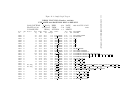
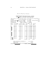
0.3
CHAPTER 0. TESTING MATE
Test Conditions
Mate can be tested at any time by running any of the following read-only
test loading patterns and comparing the results with those shown on the
following pages.
Table 5: Test Loading Patterns
lf 12 depscant
lf 13 arrscant
lf 05 depblst
lf 06 arrblst
lf 18 depseg3
There are three tables for each test loading pattern:
1. the first table displays the loading pattern and the overall results for
that loading pattern,
2. the second table contains the longitudinal strength report, and
3. the third table showns the intact stability report.
These tables are explained in Chapters 7, 8, and 9 respectively. For each
test loading pattern, your results must match the corresponding attached
summary within the discrepancies shown in Table 3.
The test loading patterns are taken from the ship’s Loading Manual.
These test patterns are in the Read Only directory /X/uldh/DATA/MATE/MAN.
These tests should be done on every Chief Mate handover in the presence
of both mates and the results logged in the Chief Mate Handover Report.
They should also be done any time the Master or Chief Mate is suspicious
of Mate’s results. The Class Surveyor will also run these tests for Survey
purposes.
The procedure for running these tests is:
1. Change directory to /X/uldh/V/TEST.
2. Carefully issue the command /X/uldh/DATA/MATE/MAN/ctx mate tests.sh.
This will delete any existing files in the TEST directory related to the
above test patterns which were left over from previous tests. You may
get some warning messages if these files don’t exist. Ignore these messages. Next the read-only test loading patterns from /X/uldh/DATA/MATE/MAN
will be copied into the TEST directory. You can tell that these test loading patterns have been freshly copied by using ls -ltr and looking
at the modification times.
3. Then issue mate loadfilename where loadfilename is the first loadfile
0.3. TEST CONDITIONS
5
name in Table 5 and generate the required reports for this loading
pattern.
4. Repeat for each of the test patterns in Table 5.
Occaisionally, Surveyors will run a test pattern, change it and make a
run, and then return to the original test pattern and run it again expecting
to see exactly the same numbers as in the first run. They need to be aware
of two things in making this test:
1. You cannot change TANKOPT during this series of tests. Suppose
in the original loading pattern tank 1C had a TANKOPT of W, a
Weight of 32345.1 tons, and an apparent percent full of 98.00%. Often
the Surveyor will make the original run, switch to a TANKOPT of P,
note the 98% full, change to a different percent and rebalance, and
then ”return” to 98.00% full. This looks like the same loading pattern
from a percentage point of view; but, if you note the new tank weight
carefully, you may find that it is as much as 2 tons different from
the original. This is because in the original pattern the tank was not
really 98% full but it might have been 98.004% full. The only way to
be sure of getting exactly the same values back is to note the value
in the input column for the original TANKOPT, change only that
column, and then change it back to exactly the original value. You
cannot change TANKOPT and expect to return to exactly the original
loading pattern.
2. Even if the loading pattern on the second run is exactly the same, the
results may be very slightly different. This is because Mate will be
starting from a different initial drafts and heel than in the first run.1
Often you cannot see the small differences in draft and heel since Mate
only displays draft and heel to three decimal places.
Refer the Surveyor to Table 3 on page 2.
1
This is true of any loading program that uses trial and error which as far as I know is
all of them. Class’s assumption that a loading program should return to exactly the same
solution is just plain incorrect. Commercial loading programs use a number of devices to
hide the fact that the results are not exactly the same.
6
CHAPTER 0. TESTING MATE
Chapter 1
Overview of CTX Mate
1.1
Capabilities
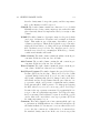
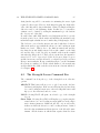
CTX Mate is a combination tanker loading program, cargo survey report
generator, and salvage and oil spill reduction package.
Loading Instrument Mate does standard tanker loading and longitudinal
strength calculations based on shear force and bending moment allowables but more accurately reflecting impact of trim and heel on cargo
location. Mate understands the difference between earth-vertical and
ship-vertical and keeps all weight and buoyant forces earth-vertical regardless of the ship’s trim and heel. Mate is not limited to symmetric
loading patterns. Mate automatically estimates hull deflection.
Survey Report Generator Mate can prepare fully filled out cargo survey
reports for each of the four standard cargo survey situations a tanker
can face: 1) before load (OBQ), 2) after load, 3) before discharge, and
4) after discharge (ROB). Mate implements Tables 6A, 6B, 54A, and
54B, allowing a fairly full range of Volume Correction Factors. This
saves ship and crew time and insures that all survey reports are free
of calculation errors. These reports may be post-processed to obtain
in-transit loss/gain, etc.
Mate’s results are commercially accurate. Mate understands the difference between tank gauging systems that work in ship coordinates
(radar, floats, etc) and systems that work in earth coordinates(surveyor
tapes, UTI, pressure, etc). In the latter category, it understands the
difference between systems that operate from a fixed point near the
deck (surveyor tapes) and systems that operate from a fixed point
7
8
CHAPTER 1. OVERVIEW
near the bottom (most pressure sensing). It also correctly handles
arbitrarily (within reason) shaped sounding pipes. Most loading programs (and many tank tables) do not correctly handle these differences
which limits them to low heel and trim situations, and even then these
programs can generate commercially significant errors.
Mate is designed so that in the normal course of events the Mate
should never need to pick up a calculator. For example, Mate allows
multiple pre-programmed dipping points for each tank. There is no
need to adjust a reading taken at one dipping point to another. The
Mate’s only responsibility is to insure that the raw data is entered
correctly. Not only does this avoid calculation errors but it means
that all calculations are consistent and completely documented.
Assuming the saab2ctx.pl
script has been correctly installed on your ship. Currently only the Saab Radar
protocol is implemented.
Auto Mode Mate has the capability of taking data directly from the tank
ullaging system. This is known as Auto mode. The user may switch
back and forth between Auto mode and Normal mode at will. The user
may remove individual tanks from Auto mode on the fly. This may
be necessary if the sensor for a tank is not operational or producing
faulty readings.
Part of a Tanker Management System CTX Mate is desiged to be an
integral part of an overall Tanker Management Information system.
The loading patterns, results, etc may be, and should be, stored in
the same voyage folders as all the other reports and correspondence
associated with that load/discharge.
Each saved loading pattern is a complete self-standing record of that
particular run including not only the loading pattern itself and the
parcel data, but also all options that were in effect at that time. If this
file is sent to the office or elsewhere, the exact run can be replicated,
both manually and by automatic post-processors which can combine
and analyse multiple loading patterns. One use of this is an automatic
pumping log generator.
Mate keeps track of variables it itself does not use, e.g. voyage number,
leg, port, berth; but which may be critically important to the overall
management system.
Intact Stability Mate computes both port and starboard righting arm
curves and checks compliance with the IMO Code on Intact Stability
A749. This can be crucially important for double hulls. It also displays
the downflooding limits. Mate may be unique among loading programs
1.1. CAPABILITIES
9
in that it calculates the roll radius of gyration. Double hull tankers
roll like pigs, especially in ballast. The main cause of this is the high
roll radius of gyration. Mate gives the crew the information they need
to minimize this quantity.1
IMO Regulation 25 Mate checks compliance with IMO Regulation 25 on
subdivision and stability.2 This regulation requires that the Master
of any tanker be satisfied that each loading pattern meets this rather
complex set of requirements. In practice, this is rarely checked because
of the inability to efficiently do the calculations. In the event of a
casualty, the failure to make these checks could have massive legal
implications. Mate also checks stability and flooding for the raking
damage mandated by IMO Reg 13F.
Damage Mode If your ship experiences a casualty, you can convert Mate
into a salvage program with a single click. This is known as Damage
Mode. You may then enter the location and extent of the damage.
Mate will immediately compute the equilibrium drafts and heel associated with this damage and the pre-damage loading pattern. Free
surface effects are computed directly, not from estimates of waterplane
inertia. These estimates can be grossly wrong in many tanker damage situations. In the case of the unusually shaped ballast tanks in
double hull tankers, they can be grossly wrong without any damage.
There is no difference between Mate’s intact and damaged stability
calculations. The user merely indicates which tanks are damaged and
where and Mate then computes the righting arms correctly accounting for any flooding and/or run off. The user can obtain a list of all
downflooding points sorted by distance above the water line.
Tank Grouping In Damage Mode, Mate allows tanks to be “grouped” on
the fly. Tanks that are grouped are treated as if they were a single
tank. This allows many forms of internal double hull damage to be
well represented including the capture of cargo in the top of the wing
ballast tanks. Tank grouping also allows us to analyse the strategy of
purposely inter-connecting tanks in order to reduce spillage.
Spill Reduction As part of the damage calculation, Mate computes the
equilibrium oil outflow from damaged tanks based on the vertical
1
Mate also computes the pitch radius of gyration which can be useful input to vessel
motions studies, SBM mooring analyses and the like.
2
In this version, Mate checks only the final flooded condition, not the intermediate
conditions.
10
CHAPTER 1. OVERVIEW
extent of the damage and the results are automatically reflected in
the hull balance, damaged stability, and strength calculations. Ullage
space over/under-pressure is accounted for as is the change in ullage
space pressure if the tank is sealed. Hydrostatic balance is integrated
into the code. Equilibrium oil-water interfaces in the damaged tanks
are computed so that the amount of cargo lost can be computed. Mate
computes and displays both hydrostatic loss and exchange loss.
This capability can serve as a ship specific, hydrostatic balance trainer
through which the crew can study a variety of potential damage scenarios and the outflow which result from alternative response strategies.
Without such training, effective use of hydrostatic balance in a real
spill is unlikely. With such training, the amount of spillage can often
be reduced by a factor of three or more, and in some cases eliminated,
by simply triming and heeling the ship properly.
Stranding Mate has a limited but useful grounding capability. For any
given grounded situation, Mate will compute the ground reaction force
and centers. All other calculations, including oil outflows, are available
when grounded. The relationship between grounding and spillage can
be crucial. For a given damage, oil spillage will generally be much
larger in stranded situations than in unstranded especially if the tide
is dropping. Mate always keeps track of the lowest point on the hull
to alert the crew to potential grounding situations.
Immediately Available Damage and spill analysis is an extension of the
normal use of CTX Mate. There is no need to change to an unfamiliar,
at best incompletely tested program in the middle of a crisis. There
are no delay prone, error prone communication and data translation
problems associated with using a totally different data format on a
computer thousands of miles from the scene. Mate will be onboard
which is the only place it can really do us any good in the event of a
big spill. The loading pattern at the time of damage will already be
on the computer, and ready to go.
And the crew will be using a program that it knows and trusts. Turning to a program the crew doesn’t know and have rarely if ever used
in the middle of a crisis simply won’t work. Since Mate is an everyday
tool, its use in a damaged situation is merely an extension rather than
a whole new ball game at a time when the ship cannot afford to fight
thru all sorts of learning and teething problems.
1.1. CAPABILITIES
11
item[Hotspot analysis] The standard strength calculation based on
Class approved allowables is appropriate only if both the structure
is undamaged and the heel is small. For salvage situations, where this
may not be the case, Mate also offers a calculation which adjusts the
hull section modulus both for loss of steel and for heel, and identifies
the points with the highest indicated stress to yield stress. We call
this Hotspot analysis. This feature uses the same description of damage as that for the oil outflow calculations, so it requires only a single
button push. This approach assumes classical beam theory. It has
some very important limitations and must be used with a great deal
of judgement. Read Chapter 13 carefully before using.
User Interface CTX Mate is equipped with a user interface which is at
least as easy to use as those associated with commercial packages.
Almost all basic functions are accessible from a single Mainscreen,
most with a single key or mouse click. The Mainscreen is scrollable
vertically and horizontally so the system can be used on any sized
monitor from a laptop on up. And the Mate retains the use of his
computer for other purposes while running CTX Mate.
Having said this, CTX Mate is not a program that can be intelligently
used or even learned by simply starting it and clicking away. Mate is
a serious tool for professionals who are responsible for up to several
hundred thousand tons of petroleum and more importantly thirty or
more lives. It can only be learned by serious study including careful
and repeated readings of this manual. For example, you must know
exactly when Mate assumes no liquid has entered or left a tank and
preserves the tank liquid mass, and when it assumes the amount of
liquid in the tank has changed. See Section 3.7. In addition to use
the Damage Mode spill calculations intelligently, you must understand
the principles of hydrostatic balance. This subject is NOT included in
this manual.
ctx hull The Mate package includes a command, ctx hull, which produces a standard hull hydrostatics table for any given heel and trim.
Optionally, a table of bonjean curves may be produced as well. This
can be used as a hull design tool like any other hydrostatic program.
Since ctx hull computes the hull properties using the same code as
Mate, it can be used to quickly compare Mate’s hull numbers with any
standard hydrostatic table.
ctx tank The Mate package includes a command, ctx tank, which serves
12
CHAPTER 1. OVERVIEW
as a computerized set of tank tables. No need for any interpolation
or trim/heel correction. The program will correct for temperature
by Tables 6A/6B/54A/54B if desired. Unlike normal tank tables,
ctx tank’s numbers are good even when the tank is almost dry and
there is a great deal of trim (and heel). ctx tank computes the tank
volume and centers using exactly the same code as Mate. So it can
be used to compare Mate tank volumes for a given ullage/innage (and
trim and heel) with those of standard tables.
ctx vcf The Mate package includes a command, ctx vcf, which calculates
VCF, WCF, and density for a given standard density (or API) and
temperature according to API Tables 6A or 6B or 54A or 54B. Various
rounding options are available.
ctx secmod The Mate package includes a command, ctx secmod, which
calculates the section moduli and other cross-sectional strength numbers for any scantling cross-section given in the ship’s Mate data base.
This command is an integral part of the CTX Tanker Design Package.
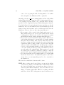
1.2
Limitations and Bugs
Mate currently has at least the following limitations:
1. Mate does not attempt to model shear flow. Therefore, the shear
allowable must be based on a worst case distribution of shear force
between longitudinal bulkheads and side shell. Mate will claim that
certain loading patterns violate shear requirements when in fact they
do not. The program should modify shear allowables according to the
transverse loading per Rule.
2. Although Mate correctly positions all loads and buoyant forces transversely as well as longitudinally, Mate currently does not have any
transverse strength capability. The long range plan is to give Mate a
Finite Element capability which will take advantage of this capability.
3. Mate is limited to trim and heel angles less than 80 degrees.
4. Mate assumes a rigid body. It estimates the vertical hull deflection
longitudinally, but hull deflection does not affect the hydrostatic or
oil outflow calculations. For the most part, this error is small and
conservative. However, in conditions involving large hull deflection
(e.g. sag of .2m or more), Mate will underestimate the outflow from
the tank in the high portions of the deflection curve (the ends for
sag) and overestimate the outflow for tanks in the low portions of the
1.2. LIMITATIONS AND BUGS
5.
6.
7.
8.
9.
10.
11.
12.
13
deflection curves. This error can have a quite noticeable impact on
equilibrium spillage.
In damaged situations, Mate computes the equilibrium spillage for the
equilibrium rigid body hull orientation and divides it into hydrostatic
and exchange flow. But Mate gives the crew no guidance as to how
rapidly that spillage will occur. This spillage can often be reduced
markedly by properly trimming and listing the ship. Mate will inform
the crew of the reduction associated with any combination of ballasting
and transfer of cargo, but only under the assumption that the new trim
and heel is implemented before any spillage takes place. In situations
in which spillage is rapid, this is not a useful approximation.
Mate does not compute outflow through tank P/V valves or vents
which can occur at high trim and heel.
Even with tank grouping, certain forms of internal double hull damage
are not well modelled. See Chapter 16.
In this version, Mate does not give the crew any information relating
to sloshing resonance. This will be corrected in later version.
Hotspot analysis is based on classical beam theory which at best is
approximately correct when the hull is undamaged, and may be wildly
misleading when the structure is damaged. But the long range goal is
to use finite element for this purpose.
It is possible for the program to fail to converge at extremely high trim
or heel for very strange shaped tanks. Mate will identify the problem
and issue an error message. In some cases, this could force the crew
to treat a tank as a fixed load. To CTX’s knowledge, this has never
happened in over 80 ship-years of actual operation. But it is possible.
Occasionally, unexpected user input will generate inscrutable error
messages. If the user does something from the keyboard or mouse
that the program cannot figure out what to do with, a window will
pop-up with an usually unhelpful error message. Most of the time this
is a harmless nuisance which can be corrected by dismissing the error
window and reentering the input. On rare occasion, it can force a user
out of his Mate session.
Graphical output is limited to bending moment and righting arm
curves, and 2-D tranverse views of selected sections. A 3-D visualization capability is in preparation.
14
CHAPTER 1. OVERVIEW
1.3
Basic Methodology
The most important difference between Mate and most commercial programs is its basic methodology. Like most loading programs, Mate balances
the hull via a trial and error process. That is, it guesses the ship’s midship
draft, trim, and heel, computes the hull buoyancy for this condition and the
centers of that buoyancy. Mate then checks to see if this buoyancy and these
centers match the weight and centers of the lightweight and all the liquids in
the tanks and compartments. If there is a discrepancy, the program adjusts
the depth, trim, and heel and repeats the process. This continues until the
buoyancy and the weights and the longitudinal and transverse centers of the
hull and the weights match, or the program gives up with an error message.
Where Mate differs from most loading programs is in the way it handles
liquid loads. For each trial in the trial and error process, Mate recomputes
the volume of liquid in each tank and the centers of that volume directly
from the tank offsets and the ullage/innage/pct volume/etc. This process
is known as direct integration. Every time it needs a tank volume or moments, it re-does the calculation that produced (or should have produced)
the corresponding tank tank table entry. In so doing, it treats each tank as
a little ship and calculates the volume and moments of that little ship up
to the current liquid level in the tank. The fact that a hull displaces liquid
and a tank or compartment retains it is almost irrelevant to Mate. It uses
the same code to compute the volumes and moments of the volume under
the current hull/tank waterlines in both cases.3
This computationally costly procedure has at least four big advantages.
1. There is no limit on heel and trim as long as they are less than 80
degrees. Mate’s computations are as accurate at very high heel and
trim as they are at zero heel and trim. Most commercial programs
do not even adjust tank centers for trim. In fact, many assume the
3
CTX offers a companion program called CTX Surveyor which can use tank tables
for its volume calculations. The purpose of this program is to satisfy cargo surveyors who
insist on using tank calibration table figures in survey reports. For small trim and heel,
there’s usually a slight difference (normally less than a cubic meter) between the tank
table numbers and Mate’s more accurate direct calculations for the same tank readings,
draft, trim and heel. Both CTX Mate and CTX Surveyor use the same format for loading
pattern files which allows loading patterns to be passed back and forth. The cargo survey
reports that are generated use the same format, so post-processing software can handle
either. And they both have a similar user interface. However, CTX Surveyor is not a
Loading Instument. It cannot check strength. It cannot check stability. The drafts and
heel need not be consistent with the loading pattern. CTX Surveyor merely automates
the calculations that a cargo surveyor does. In a rational world, CTX Surveyor would be
completely unnecessary.
1.4. ABOUT THIS MANUAL
15
LCG of a tank is the same regardless of ship orientation and tank
ullage. Gravitational forces remain earth vertical regardless of the
ship’s orientation.
2. For intact tanks, the shift in the tank liquids and its effect on trim
and stability are computed directly. There is no need to make any
assumptions about the form of the free surface. This is important
because the normal assumptions based on waterplane moments can be
grossly wrong at the high heels and trims that may be encountered
in a damage situation and for the unusually shaped ballast tanks of a
double hull tanker. With double hulls, intact tanker stability is once
again a real issue and the normal treatment of free surface can be
fatally in error.
It also implies that Mate’s computations in no way depend on the
bottom of the tank being totally flooded (nor the top of the tank
being totally dry). The “wedge problem” does not exist.
3. For damaged tanks, the program can adjust the liquid volume to the
assumed draft and trim and heel and correctly compute both the flooding/runoff, and the amount of oil outflow at hydrostatic balance in the
tanks, and then feed the effect of this change into the determination of
the equilibrium draft, trim and heel. The amount and composition of
liquid in a damaged tank or compartment is not fixed but depends on
the ship’s draft and trim and heel and in turn helps determine what
that draft, trim and heel will be. Mate’s brute force approach allows
it to handle the fact that tanker loads are not fixed but rather both
depend on and determine the ship’s orientation.
4. Important numbers such as the roll and pitch radii of gyration, which
are crucial to the ship’s dynamic response to a particular set of sea
conditions come almost for free. A standard loading program cannot
compute these numbers.
1.4
About this Manual
This manual can be displayed on your terminal by seleting Manual from the
Help menu. It is in PDF format. After you have displayed the manual, you
can search for a particular phrase, or print out all or a portion, using the
tools on the display window.
This manual has several companion documents:
The Physics of Tank Spillage Understanding this CTX Technical Report is essential to handling damage in a manner that minimizes oil
16
CHAPTER 1. OVERVIEW
spillage. It can be accessed on-line from the Mate Help menu.
Not yet available.
CTX Mate Designers Manual This manual is aimed at users who are
employing CTX Mate as a design or evaluation tool, rather than a
Loading Instrument.
CTX Mate Ship Data Preparation Guide This document describes the
procedure for generating and testing the ship specific data files that
Mate requires in order to be able to perform its functions for a particular ship. However, it is also the source for a description of these files
and is easily readable by any deck officer. A copy should be on-board
and studied by deck officers interested in deepening their knowledge
of Mate and their ship.
CTX Mate Installation and Administration This document describes
how to install or re-install Mate. This may be required not only for
upgrades but in the event of a hardware failure. A copy of this document must be on board every Mate equipped ship and at least one crew
member familiar with and capable of performing these procedures.
Not yet available.
CTX Mate Programmer’s Manual This document is aimed at personnel who are responsible for maintaining and improving Mate. But it
also contains a great deal of information on basic methodology which
could be useful to anybody using the program, especially those who
have a little computer experience.
Chapter 2
Getting Started
There are two ways of starting CTX Mate:
1. Clicking on the Mate icon (the ugly capital M) on the desktop.
2. Typing a mate command into a terminal window.
Using the command line is more flexible and often quicker, especially
when you are repeating similar runs. But for untrained people clicking
on the icon is easier. Section 2.1 describes the icon method; section
2.2the command line method. If you don’t have a Mate icon on your
desktop, you will have to turn to Section 2.2.
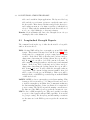
2.1
Launching Mate from the Desktop Icon
When you double click on the Mate icon, you will be presented with
the Mate start-up form.1 This form allows you to choose a fleet, a
ship, a voyage (or TEST), and an initial loading pattern.
Mate attempts to pre-select these values in a manner such that most
of them should already be the ones you want. For each such variable,
you can check out the alternatives via clicking on the arrow. When
you do this a list of the possibilities will drop down and you can select
one of these by clicking on it. The following values need to be selected.
Fleet Select a fleet from the drop down list. In most on-board cases,
you will have only one choice, the fleet to which your ship belongs,
1
On most systems, the icon can be drag and dropped onto the panel (or dock). Then
it is always visible and you can launch Mate with a single click.
17
18
CHAPTER 2. GETTING STARTED
in which case you can ignore this box.
Ship Select a ship from the drop down list. In most on-board situations, you will have only one choice, your own ship, in which case
you can ignore this box.
Voyage Number This variable determines the voyage (or TEST) folder
in which the Mate calculations will take place and the reports will
be filed. That folder will be /F /ss/V/NNN /CARGO where F is
your fleet code, ss is your ship code, and NNN is the three digit
voyage number. See Section 2.3 for what little you need to know
about Mate’s filing system. The voyage number must be exactly
three digits. The ship’s seventh voyage has a voyage number of
007, not 7. Initially, Mate will display the ship’s current voyage
(or TEST if none exists).
The list will show all the ship’s past voyages, plus TEST and NEXT.2
TEST should be used for Mate testing and training to avoid conflicts with the real voyages. If NEXT is selected, Mate will create
a new voyage directory whose number is one greater than the
largest voyage number which already exists.3
Loading pattern Select an initial loading pattern from the drop
down list. This is the loading pattern from which the Mate calculations will commence. Initially, Mate will display the voyage’s
most recently modified loading pattern in this field. Attempt to
pick a pattern that is as close to the one you expect to end up
with as possible. However, you will be limited in your choices to
the patterns already in the selected voyage directory. If you want
a more complete choice of initial patterns, you will have to work
from the command line.
If there are no load files in the selected directory, Mate will put
a small number of standard loading patterns in the directory.
After you are satisfied with the start up form, click on the MATE
button and, after a short delay, a large window, the Mate Mainscreen, will pop up.4 You will also get a background window entitled
Mate Log File. This background window will keep track of warning
2
And possibly DEMO. DEMO applies only to the CTX Mate demonstration ships.
Some owners restrict the creation of new Voyage directories in which case an attempt
to make a new voyage directory from the Mate start-up form will raise an error. In this
case, ask your Captain or other authorized personnel to create the new directory for you.
4
Provided you have the proper permissions, and Mate’s self-test is successfully completed. If you don’t get a Mainscreen, check the launch window for error messages. To
3
2.2. FROM THE COMMAND LINE
19
messages and, God forbid, abnormal errors. It will be almost entirely
obscured by Mate’s Mainscreen. If Mate is not responding the way
you think it should, move the Mainscreen to the right to read the Log
File. With luck, it will explain what the problem is. In the rest of this
manual, the Log File is referred to as the launch window.
It is possible and easy to run multiple Mate sessions at the same time.
Simply click on the Mate icon more than once. However, if you do
this, we strongly recommend that you put each Mate session on a
different desktop For example, you might have one session monitoring
a discharge in Auto mode (taking readings directly from the ullaging
system) on one desktop and another Normal mode planning session
where you are working out your post-discharge ballasting pattern on
another desktop. Multiple Mate sessions on the same screen can get
confusing.
Now turn to Chapter 3 for instructions on manipulating the Mainscreen.
2.2
Starting Mate from the command line
Starting Mate from a desktop icon is convenient but limiting. To obtain the full power and flexibility of Mate, it must be started from the
command line. And with practice you will find that the command
line method is not only more powerful, but where multiple runs are
involved — as they almost always are — can be quicker and easier.
However, command line use (and this section) assumes that you know
how to bring up a terminal window, copy and move files, and move
around the file system using the change directory command (cd or
equivalent).
Mate should always be used from the proper directory which for normal
operations is /F /ss/V/NNN /CARGO where F is your fleet code, ss is
your ship code, and NNN is the three digit voyage number. See Section
2.3 for what little you need to know about Mate’s filing system.5 All
run Mate, you must have Read permission on the ship’s Mate data directory and Write
permission on the voyage directory you are working in. See Section 2.3.
5
For training purposes and only for training purposes, run Mate from the
/F /ss/V/TEST directory. Load files in V/TEST cannot be protected. Any work you do
in V/TEST will eventually be over-written and lost.
In non-operational environments – for example, when Mate is being used as a tanker
design or evaluation tool – Mate may be run in non-voyage directories. See Section 2.4.
20
CHAPTER 2. GETTING STARTED
the documents for this voyage’s load/discharges should be filed in this
directory.
You will need a loadfile containing an initial loading pattern. If a
file containing a suitable such pattern does not already exist in the
current directory, copy one in. Usually the initial loading pattern will
be a loading pattern similar to the one you intend to use; but it can
be any loading pattern that has all the tanks that you will be using.
If no other pattern exists, you may copy /F /ss/DATA/MATE/lf ltwt.
Then to run Mate simply issue
mate lf ltwt &
And a large window called the Mainscreen will appear. To repeat, to
run Mate:
1. Switch to the directory appropriate for the load/discharge to be
analyzed.
2. Type
mate loadfile &
where loadfile is the name of a loading pattern file which must be
in the same directory.
That’s all there is to it. The window in which you type the mate
command is called the launch window. The ampersand at the end of
the above command is optional but it allows you to be able to use the
launch window while you are running Mate. If you do not have the
proper permissions, or Mate detects an unrecoverable error in the input
or encounters other unusual problems, it will print an error message
to the launch window and (sometimes) abort. If things appear amiss,
check the launch window for error messages, and then refer to Chapter
22.
The above example assumes that the fleet code and ship code has been
properly set for the ship of interest. On-board this will always be the
case. In the office, where we have to deal with a number of different
ships, Mate uses the environment variable FLEET to keep track of the
fleet code and the environment variable SHIP for the ship code. On
some systems, these two environment variables are automatically set
whenever you switch to a particular ship’s directory, which is normally
exactly what you want. These two variables can also be set manually
by issuing
mate --fleet=F --ship=ss loadfile
2.2. FROM THE COMMAND LINE
21
where F is the desired fleet code and ss is the desired ship code You
will only need to reset the FLEET or SHIP variables when you change
fleet or ship.
Finally, you can include --voy=NNN in the command line to both
switch you to particular voyage directory and set the VOY environmental variable. For example,
mate --fleet=A --ship=em --voy=TEST lf selftest
will run Mate on lf.selftest in the V/TEST directory of A fleet ship
em.6 Once again you will only have to reset VOY when you change
voyages.
Notice that Mate’s loading pattern files start with lf , that’s ell-eff.
If you create a load file manually, always follow this convention. Conversely, files that are not Mate loading patterns should never start
with lf .
6
-f is shorthand for –fleet=. -s is shorthand for --ship=. -v is shorthand for –voy=.
So the shorthand form of this command is mate -fA -sem -vTEST lf selftest.
22
CHAPTER 2. GETTING STARTED
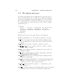
2.3
The CTX Mate Folders
Mate is designed to be very easy to use, but not without some
preliminaries.7 Before you can begin to use CTX Mate, you must
understand the file folder system Mate uses.
Mate assumes that the Tanker File System (TFS) is broken down by
fleet and within fleet by ship.8 Each fleet (there may only be one in
your case) is given a one character fleet code, and a top level directory
whose name is the fleet code.9 Thus, if your owner or manager is
responsible for three fleets: they might be assigned fleet codes: A, B
and C. And there will be three top level fleet directories: /A, /B and
/C.10 If your ship is in the B fleet, then you will probably only have
the /B directory on your on-board computer.
Within each fleet, each ship is given a two to four character ship code.
For example, if fleet A consists of the ships, Alhambra, Orpheum and
Tara. These ships might be given ship codes of al, or, and ta. And
each such ship will be given a sub-directory in the A fleet directory
whose name is the ship code. In this case, there will be three ship
directories /A/al, /A/or, /A/ta in the /A fleet directory. On-board,
you will probably only have your own ship’s ship directory.11
All of the information pertaining to a particular ship should be filed
somewhere in that ship’s ship directory. If your owner follows the
CTX Tanker Filing System (TFS), the complete description of where
all this data must be filed is given in The CTX Tanker Filing System
Manual?? which runs to several hundred pages. Fortunately, for Mate
purposes, only a very small portion of the TFS is relevent or necessary.
In fact, we only need to deal with the following folders.
7
Commercial programs on the other hand are designed to easy to start up without
any preliminaries. Commercial vendors know this is an important selling point. The cost
of this is that it is extremely difficult to integrate the loading program within an overall
tanker management system.
8
This is hardly a CTX invention. Almost all owners and ship managers do this, but
often the system is not fully enforced across the organization.
9
For the purposes of this manual, folder and directory are synonyms.
10
Some owners use fleet code X for ships they have interest in but don’t actually own;
for example, a ship they are considering purchasing.
11
The ship code need only be unique within a fleet. In the preliminary design context,
the fleet code often signifies a project ID and the ship code becomes a varient design, eg
/A/0021/, might be the 21st varient in a project to design an Aframax tanker. In the
newbuilding contest, fleet code often is really a yard code, and ship code becomes a hull
number.
2.3. MATE FOLDERS
23
/fleet/ship/DATA/MATE This is the read-only folder where all
the ship’s data Mate needs is stored. This includes, the ship particulars, hull offsets, tank descriptions, lightweight distribution,
allowables, etc. For a typical tanker, this directory contains some
60 files. In order to use Mate, you must have Read permission on
this directory. All the data is in human readable, self-identifying
form. You can examine any of these files (for example, with an
editor); but you cannot change them.
/fleet/ship/V/voy /CARGO Each voyage is given its own folder
in the TFS. This folder, whose name is the voyage number is in
the ship’s V directory. The voyage number is three digits, sequential including the leading zeros: 001, 002, and so on. The
cargo related data for each voyage is filed in that voyage’s, CARGO
folder. If your ships is currently on her 19th voyage, then everything to do with cargo handling on this voyage, should be
in /fleet/ship/V/019/CARGO. This is where Mate’s loading patterns for the 19th voyage should be filed. In order to use Mate
operationally, you must have Write permission on the CARGO
sub-directories.
/fleet/ship/V/TEST V/TEST is a special directory where you can
play around with Mate without affecting any of the “real” loading
patterns in the voyage CARGO folders. It is intended for training
and testing only. Never use V/TEST for real loading patterns.
Files in this directory cannot be protected and will eventually be
over-written and lost.
24
CHAPTER 2. GETTING STARTED
2.4 Using Mate outside the Tanker File System
It is possible to use Mate without accepting any part of the CTX
Tanker File System. This can be useful is some non-operational applications; but is almost always a terrible idea on-board in actual tanker
operations.
You may specify the three folders that Mate needs directly via issuing
the following command
mate --ship dir=xxxx --load dir=yyyy --rep dir=zzzz loadfile
where xxxx is the full pathname of the directory containing Mate’s ship
data, yyyy is the full pathname of the directory containing the intial
loading pattern file, zzzz is the full pathname of the directory where
you want the reports to be filed, and loadfile is the initial loading file
name. If you delete the --rep dir option, Mate will assume that the
report directory is the same as the load dir. These options will override the current FLEET, SHIP and VOY variables. You must have
Read permission on ship dir and load dir and Write permission on
rep dir.
This form of the Mate command can be used if you want to base a
Mate report on a loading pattern which is in a directory for which you
do not have Write permission. For example, an owner may elect to put
the loading patterns that are sent in from the ships in folders which are
read-only for office personnel to prevent the office from inadvertantly
(or otherwise) changing these patterns.
Tha real intended use of this form of the Mate command is in nonoperational applications where the /fleet/ship/voyage breakdown is
not appropriate. But it can used operationally by owners who for
whatever reason do not think this is a logical structure. However, if
they do so, they will not be able to launch Mate from the desktop.12
12
Unless they write a specialized start-up script. This is not a big job. See the Mate
Programmer’s Manual.
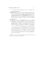
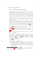
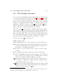
Chapter 3
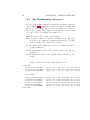
The Mainscreen
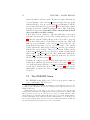
3.1
The Five Sections
When you start Mate either by clicking on Go in the start-up form
or with a mate command, it will take Mate a few seconds to read in
all the hull and tank offsets and then balance the ship for the initial
loading pattern. If all goes well, Mate will then display a large window.
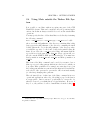
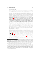
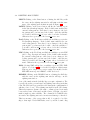
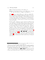
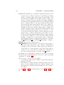
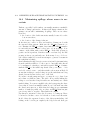
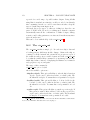
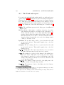
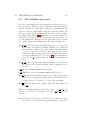
which is known as the Mainscreen. Figure 3.1 show a highly simplified
Mainscreen. 1 To see the Mainscreen in all its glory, fire up a Mate
session. The Mainscreen will stay on your terminal until you end
this Mate session. To activate the Mainscreen, the mouse must be
somewhere in this window.
The Mainscreen consists of five sections:
Titlebar Along the top of the window, you will find a Titlebar which
shows the ship’s name and the key options being used in this
run including the name of the current loading pattern. These
somewhat cryptic options are explained in Section 3.6. You can
use the Titlebar to move the Mainscreen around, resize it, and
iconify it – just like any other window.
Menubar Just below the Titlebar, you will find the Menubar, from
which all Mate functions can be accessed via dropdown menus.
The individual menus are discussed in Section 3.4.
1
Figure 3.1 shows Mate in Normal mode. In Damage and Auto modes, the Mainscreen will look a little different. These differences are discussed in Chapters 16 and 15
respectively.
25
26
CHAPTER 3. THE MAINSCREEN
Tank Table Most of the Mainscreen is taken up by the Tank Table.
The Tank Table contains one row for each tank/compartment.2
You probably cannot see all the tanks at once. Fortunately, the
Tank Table is scrollable. One of the cells in the Tank Table is
highlighted. The highlighted cell is shown in a different color from
the other cells and it contains a blinking editing cursor. You can
change the highlighted cell with the arrow keys moving about the
Tank Table at will. When you attempt to move the highlighted
cell off the table, the table will scroll if the table extends beyond
that edge. Therefore, if you want to scroll the table up, move the
highlighted cell down to the bottom with the DOWN-ARROW
key. When it hits the bottom line of the Tank Table, the next
DOWN-ARROW press will scroll the table up one line, if lines at
the bottom are currently obscured. You can also move about the
table with the mouse by positioning the mouse pointer over a cell
and clicking on it. The highlight will move to the cell that you
just clicked on. But you can’t scroll the table with the mouse.
The Tank Table also scrolls horizontally via the LEFT-ARROW
and RIGHT-ARROW keys but this is usually necessary only in
damage calculations.
At the bottom of the Tank Table, there will be one row for each
point load. Point loads are weights that count against deadweight
but are not treated as liquid. These include such things as crew,
stores, fluids in engine room piping, and possibly very small tanks.
It is by making changes to the Tank Table that you will create new
loading patterns to study. This process is described in Section
3.2.
Summary The fourth section of the Mainscreen is the Summary.
This area displays the main results from the most recent recomputation of the hull balance. Most of the entries are selfexplanatory. However, if in doubt, check the Glossary for a complete set of definitions. The Summary is described in Section 3.3.
You cannot change any part of the Summary section directly.
If you change the loading pattern by editing the Tank Table, the
Summary will not change until you rebalance the ship. Until this
2
Mate’s “tanks” include all the major compartments in the hull. As far as Mate
is concerned, an Engine Room or a Pump Room is a perfectly good “tank” and such
tanks can be crucially important in damaged situations. Howvever, as we shall see, an
empty/dry tank/compartment may be hidden, in which case that compartment will not
be displayed in the Tank Table unless the proper show hidden option is ineffect.
3.1. THE FIVE SECTIONS
27
is done, the Summary will not be consistent with the Tank Table
loading pattern. When this happens the background color of the
Summary will switch to yellow to warn you of that fact.
Toolbar The final section of the Mainscreen is a Toolbar that runs
along the bottom. It contains 12 buttons which match the 12
Function keys at the top of your keyboard. The most common
and/or critical Mate functions can be accessed with a single click
via the Toolbar. You may tell Mate which Toolbar function you
want by either clicking on that button in the Toolbar or by hitting the corresponding Function key. The Toolbar is discussed in
Section 3.5.
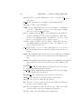
You can exit a Mate session several ways:
1.
2.
3.
4.
Selecting Quit from the File menu or directly from the Toolbar.
Hitting Shift-F12.
Clicking on the X button in the Title bar.
Typing Cntl-C in the Launch window.
In the first case, you will be warned if the current loading pattern
has not been saved. Mate will ask if you really want to quit. Hitting
Shift-F12 ends the Mate session without asking for confirmation. The
current loading pattern will be lost unless you save it first.
Quit will not work until Mate finishes whatever it is doing. If you
start a very long computation that you want to abort, or you just
get hopelessly messed up, you can always get rid of the current Mate
session by hitting Cntl-C (Hold down the Control key and hit C) with
the cursor in the launch window. Of course, you will lose the current
loading pattern unless you have already saved it.
Leaving Mate via Cntl-C has another, more important purpose. Mate
automatically maintains a Log File of all its operations in a particular session. Normally, this Log File together with a number of other
temporary files is deleted at the end of the session.3 But if you exit
Mate by hitting Cntl-C, these files are not deleted. If you think Mate
is not functioning properly, use Cntl-C to quit; and you will have a
history of the session in the Log File which should be emailed to CTX
together with your comments. See Chapter 17 for details.
One drawback of using Cntl-C is that these temporary files will have
to be removed manually.
3
If Mate thinks that something is amiss, the Log File will be saved automatically.
28
CHAPTER 3. THE MAINSCREEN
The Mate Mainscreen is simply one more window on your monitor.
By moving the mouse off the Mainscreen, you can do anything you
want in other windows (including starting up another Mate session).
Thus you can be looking at an Mate run while you prepare a telex
or email into which you insert some of the information on the Mate
screen. Conversely, unless the mouse pointer is somewhere on the Mate
screen, the screen where it is will receive all your input not Mate. So
you can activate and deactivate the Mate screen by moving the pointer
on and off of it.
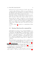
While the Mainscreen is showing, anyone who has access to the keyboard can use any of these commands, potentially wiping out a valuable file. If the Chief Mate leaves the keyboard, he should move the
mouse off the Mainscreen to make this a little more difficult. Of course,
if the Chief Mate is going to leave the Cargo Control Room, he should
save the current loadfile and log off. Otherwise, not just Mate but the
entire portion of The File System to which working group CMATE has
access is open to anyone who wanders into the CCR. It will only take
a few seconds to bring Mate back, when he returns.
If you haven’t done so already, start a Mate session and play around
with the above commands. Do this in /fleet/ship/V/TEST to avoid
interfering with the “real” loading patterns.
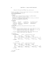
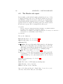
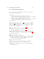
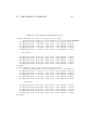
CTX MATE 0.40-BASE using AT SEA, API/SG .01/.0001, F/C .1/.01, 0_Inn/Wedge for HELLESPONT TARA on /X/uldh/V/DEMO/lf.al98dep
File
TANK
Edit
View
Export
|O|PT|CGO| API | TEMP|
Cargo
SG
Reports
Mode
PARCELS
SAVE_LD
Sort
Help
DRAFTMID
DRAFT AP
DRAFT FP
TRIM
HEEL
PROP IMM
GM corr
PRINT
23.240
26.892
19.588
-7.304
-0.136
15.000
8.802
20.00|
98.00|
98.00|
98.00|
98.00|
98.00|
98.00|
98.00|
98.00|
98.00|
98.00|
98.00|
98.00|
98.00|
98.00|
98.00|
98.00|
98.00|
98.00|
98.00|
98.00|
90.92|
90.92|
90.92|
90.92|
90.92|
90.92|
90.92|
90.92|
90.92|
|
51752|
299519|
299518|
299518|
271983|
137464|
137464|
93801|
93801|
93801|
93801|
187601|
187601|
93801|
93801|
93801|
93801|
130263|
130263|
41112|
40061|
3458.2|
4150.8|
1240.8|
805.9|
603.0|
603.0|
250.1|
250.1|
190.8|
|
AL 2964525 TOV
BEND.
6995.3|
40485.9|
40485.9|
40485.9|
36764.0|
18581.0|
18581.0|
12679.1|
12679.1|
12679.1|
12679.1|
25358.0|
25358.0|
12679.1|
12679.1|
12679.1|
12679.1|
17607.6|
17607.6|
5557.1|
5415.0|
3415.4|
4099.3|
1225.4|
795.9|
595.5|
595.5|
247.0|
247.0|
188.5|
5.0|
2964525 GSV
STAB.
FLOOD
0.0|
0.0|
0.0|
0.0|
0.0|
0.0|
0.0|
0.0|
0.0|
0.0|
0.0|
0.0|
0.0|
0.0|
0.0|
0.0|
0.0|
0.0|
0.0|
0.0|
0.0|
0.0|
0.0|
0.0|
0.0|
0.0|
0.0|
0.0|
0.0|
0.0|
|
0.0|
0.0|
0.0|
0.0|
0.0|
0.0|
0.0|
0.0|
0.0|
0.0|
0.0|
0.0|
0.0|
0.0|
0.0|
0.0|
0.0|
0.0|
0.0|
0.0|
0.0|
0.0|
0.0|
0.0|
0.0|
0.0|
0.0|
0.0|
0.0|
0.0|
|
400715 MT
DAMAGE
GSV
| Wtrvol | Nonvol |
51752|
299519|
299518|
299518|
271983|
137464|
137464|
93801|
93801|
93801|
93801|
187601|
187601|
93801|
93801|
93801|
93801|
130263|
130263|
41112|
40061|
3458.2|
4150.8|
1240.8|
805.9|
603.0|
603.0|
250.1|
250.1|
190.8|
|
0.0
0.0
0.0
0.0
0.0
0.0
0.0
0.0
0.0
0.0
0.0
0.0
0.0
0.0
0.0
0.0
0.0
0.0
0.0
0.0
0.0
0.0
0.0
0.0
0.0
0.0
0.0
0.0
0.0
0.0
BLINDZONE
365
MANI_HT_S 12.457
MANI_HT_P 12.318
DISPLCMENT 480052
MAX SHEAR
19843
MAX BEND -1614795
MAX HOG
-0.416
VISUAL
|
|
|
|
|
|
|
|
|
|
|
|
|
|
|
|
|
|
|
|
|
|
|
|
|
|
|
|
|
|
|
0.0
0.0
0.0
0.0
0.0
0.0
0.0
0.0
0.0
0.0
0.0
0.0
0.0
0.0
0.0
0.0
0.0
0.0
0.0
0.0
0.0
0.0
0.0
0.0
0.0
0.0
0.0
0.0
0.0
0.0
|
|
|
|
|
|
|
|
|
|
|
|
|
|
|
|
|
|
|
|
|
|
|
|
|
|
|
|
|
|
|
GOV
LOW_PT
-26.76
DEPTH
100.00
MIN_FLOOD 5.26
AT
FR013
LCB
186.66
TCB
0.04
VCB
12.24
REG_25
| OFF
|
51752|
299519|
299518|
299518|
271983|
137464|
137464|
93801|
93801|
93801|
93801|
187601|
187601|
93801|
93801|
93801|
93801|
130263|
130263|
41112|
40061|
3458.2|
4150.8|
1240.8|
805.9|
603.0|
603.0|
250.1|
250.1|
190.8|
|
UNUSED
|
|
|
|
|
|
|
|
|
|
|
|
|
|
|
|
|
|
|
|
|
|
|
|
|
|
|
|
|
|
|
DRAFT MARKS
AftP 26.641
AftS 26.548
MidP 23.497
MidS 23.336
FwdP 19.950
FwdS 19.866
QUIT
29
REDO
Rounding
|ULLAGE|INNAGE|%FULL | VOLUME | WEIGHT |FREEWTR|NONLIQ|
1C
|P|UL|AL| 34.56| 60.0|0.8502|26.301| 6.549|
2C
|P|UL|AL| 34.56| 60.0|0.8502| 1.140|31.716|
3C
|P|UL|AL| 34.56| 60.0|0.8502| 1.138|31.710|
4C
|P|UL|AL| 34.56| 60.0|0.8502| 1.147|31.716|
5C
|P|UL|AL| 34.56| 60.0|0.8502| 1.205|31.657|
1P
|P|UL|AL| 34.56| 60.0|0.8502| 1.122|31.284|
1S
|P|UL|AL| 34.56| 60.0|0.8502| 1.118|31.281|
2F_P
|P|UL|AL| 34.56| 60.0|0.8502| 1.518|30.885|
2F_S
|P|UL|AL| 34.56| 60.0|0.8502| 1.404|30.905|
2A_P
|P|UL|AL| 34.56| 60.0|0.8502| 1.595|30.862|
2A_S
|P|UL|AL| 34.56| 60.0|0.8502| 1.505|30.888|
3P
|P|UL|AL| 34.56| 60.0|0.8502| 1.353|31.042|
3S
|P|UL|AL| 34.56| 60.0|0.8502| 1.345|31.064|
4F_P
|P|UL|AL| 34.56| 60.0|0.8502| 1.510|30.885|
4F_S
|P|UL|AL| 34.56| 60.0|0.8502| 1.485|30.909|
4A_P
|P|UL|AL| 34.56| 60.0|0.8502| 1.541|30.853|
4A_S
|P|UL|AL| 34.56| 60.0|0.8502| 1.523|30.877|
5P
|P|UL|AL| 34.56| 60.0|0.8502| 1.599|30.854|
5S
|P|UL|AL| 34.56| 60.0|0.8502| 1.565|30.879|
SLOP_P |P|UL|AL| 34.56| 60.0|0.8502| 1.617|31.011|
SLOP_S |P|UL|AL| 34.56| 60.0|0.8502| 1.559|31.074|
1FO_P
|P|UL|f1|0.9876|15.00|0.9876| 2.576|23.551|
1FO_S
|P|UL|f1|0.9876|15.00|0.9876| 2.797|23.239|
2FO_P
|P|UL|f1|0.9876|15.00|0.9876| 1.666|14.156|
2FO_S
|P|UL|f1|0.9876|15.00|0.9876| 1.157|13.752|
3FO_P
|P|UL|f1|0.9876|15.00|0.9876| 1.396|12.328|
3FO_S
|P|UL|f1|0.9876|15.00|0.9876| 1.300|12.211|
FO_SET_P|P|UL|f1|0.9876|15.00|0.9876| 7.819|11.804|
FOSRVSTP|P|UL|f1|0.9876|15.00|0.9876| 7.489|11.810|
FO_SRV_P|P|UL|f1|0.9876|15.00|0.9876| 7.461|11.850|
CREW
| | | |
|
|
|
|
|
DWT
412129 29432 LT Sdwt
CARGO
400715 TPC
231.8
BLLST
0 MTC
6098
BFO
11409 WETTED
36332
OTHER
5 SEA_SG 1.0234
MAX %SHEAR -70.7% at
FR040
MAX %BEND -148.1% at
FR090
Options
3.1. THE FIVE SECTIONS
Figure 3.1: Simplified Normal Mode Mainscreen
30
CHAPTER 3. THE MAINSCREEN
3.2
3.2.1
The Tank Table
Editing the Tank Table
Making changes to a loading pattern via the Tank Table is straightforward.
1. When the Mainscreen first appears, the highlighted cell will be in
the top row of the Tank Table. Move the highlight to the cell you
want to change either by clicking on the desired cell or by using
the arrow keys. You may have to use the arrow keys to scroll to
the cell you want to change.
2. Once the highlight is on the right cell, simply type in the new
value. As soon as you start typing, the old value will disappear.
By hitting Escape before leaving the cell, you can make it reappear. You can Backspace over any mistakes. A blinking cursor
indicates where you are in the cell.
You can overwrite individual letters or numbers by hitting the
Insert key. The blinking cursor will change color and become fatter. While in this mode, any (legal) character you type in will
overwrite the character under the cursor. To move the blinking
cursor without destroying anything, use Ctrl-Left (Hold the Control key down and press LEFT ARROW) and Ctrl-Right. To
revert to the normal mode, hit the Insert key again.
Mate will reject entries which it can see are illegal – for example, a
letter in a cell which should be a number. In this case, it will beep
and ignore your entry. It will reject any attempt to enter data into
a column which is display only and sometimes will automatically
move you to what it thinks is the proper column. For example,
if you have specified tank option U (user enters ullage) and you
attempt to change the Innage column for that tank, Mate will
reject the entry and move to the Ullage column.4
3. When you are satisfied, leave the cell either by hitting Return
(labeled Enter on some key boards) or by using the arrow keys.
The change has no effect until you leave the cell or hit one of the
commands that rebalance the ship. When you leave a changed
4
Sometimes Mate will move to a column which is not in the currently visible portion
of the Tank Table. This is a nuisance for it will appear that you have lost the highlighted
cell. Either click on another cell or scroll the table sideways until the highlighted cell
appears. We hope to fix this in future versions of Mate.
3.2. THE TANK TABLE
31
cell, the cell will change color for a moment. This tells you that
the new value has been accepted. Until you see the color flash,
the old value is in effect. If you leave a cell and then decide you
made a mistake and want the old value back, you must make
the cell all blanks, leave it, rebalance, and the old value will be
restored. Obviously, it’s simpler to hit Escape before leaving the
cell. Also, if you want to set a cell to zero, you must type in a
zero, not blanks.
Both the Down Arrow key and the Return (aka Enter) key will move
you down one row. But there is an important and useful distinction.
If you leave a cell by hitting Return, Return will remember that entry.
If you hit Return again upon entering another cell, the new cell’s value
will be replaced by the last cell you left via Return. Say you want to
change a whole bunch of tanks to the same value, say 98% full.5 Go to
the top of the %FULL column, change the value to 98.0 and hit Return.
Then just keep hitting Returns and each tank in turn will be changed
to 98.0. This only works for Return, so if you want to skip one or
more tanks (not change them to 98), use the Down Arrow to move
over those rows. And this only works if Return is the first key you hit
upon entering a cell. To repeat: if Return is the first key press in any
cell, that cell will be immediately changed to the same value as the last
cell which was left by hitting Return. This can be a big time-saver in
the early stages of searching for the best loading pattern.
3.2.2
The Tank Table Columns
Making changes is easy; but what are we changing? Here starting from
the left are the columns in the Tank Table and their meanings:6
TANK The leftmost column contains the tank/compartment code.
You cannot change the tank code column.7 This means that you
cannot add a tank or compartment that is not already in the
initial loading pattern from the Main Screen. To do this you
must either select the SHOW HIDDEN option from the View
5
This example assumes that OPT has been set to P for all these tanks, but the same
trick works for ullages and innages provided the OPT is properly set.
6
These are the Normal and Auto mode columns. Damage mode has a somewhat
different set of columns. See Chapter 16.
7
But you can re-order the tanks via the Sort menu.
32
CHAPTER 3. THE MAINSCREEN
menu (See Section 3.4 or edit the loadfile directly (See Chapter
6).
At the bottom of the Tank Table, most loading patterns will
have one or more “tanks” for which the CGO (third column) is
fi. Each such row is not a tank but a point load that is regarded
as fixed in space. Such loads include stores, crew and effects,
minor tanks which are not explicitly included in the tanks listed
in the loading pattern, etc.
OPT The second column is labeled OPT. This is a very important
column by which the user specifies which tank OPTion to use for
each tank. His possible choices and their meanings are:
U Tank is intact, user wishes to specify ullage.8
I Tank intact, user wishes to specify innage
P Tank intact, users wishes to specify percent full (volumetrically)
V Tank intact, users wishes to specify volume directly
W Tank intact, users wishes to specify weight directly
E Tank is intact and empty.
H Tank is intact and empty and hidden.
F Tank is free flooding, started out empty
D Tank is damaged, user wishes to specify damage location and
ullage space pressure (often 0 gage for a vented tank).
S Tank is damaged and sealed. In this case, Mate’s uses the perfect gas law to estimate the equilibrium ullage space pressure.
This OPT can be chosen only in Damage mode.
G Tank is to be grouped with another tank, that is, this tank
should be treated as if were part of the tank with which it
is grouped. This OPT can be chosen only in Damage mode.
This option is used to model certain kinds on internal damage
or purposely connecting two tanks in order to reduce outflow.
See Chapter 16 for details.
OPT can be entered in either upper or lower case, but lower case
will be converted to upper. Notice the tank option is a single
8
If you have specified a pressure sensing, H type gauging system (see PT below), ullage
has no real meaning. Therefore, Mate will not accept an OPT of U for tanks with H type
gauging systems. In this case, Mate will change the OPT to I with a warning telling you
why it had to make this change.
3.2. THE TANK TABLE
33
character and there are only a few legal values. Anything else
will be rejected. Depending on the value of OPT, only changes
in certain columns have any impact on the rebalance. If OPT
is U, only ullage counts and changes in the INNAGE, %FULL,
VOLUME, and WEIGHT columns will have no effect and are
rejected. Similarly, if opt is P, then only %FULL counts and
changes in ULLAGE, INNAGE, VOLUME, and WEIGHT are
rejected. In short, always check the OPT column when making a
change to a particular tank. If you want to change the %FULL
and OPT is U, you must change OPT to P (or p) before entering
the percent full.
For point loads, OPT has no meaning and is blank.
PT The third column contains a two character code specifying the
Gauging Point/Measurement System which was used in making the reading. Mate allows each tank to have multiple dipping points/measurement systems which means you must specify
which one you are currently using. The code must match one of
the dipping points in the tank’s CTX file. Case is important: WH
and wh are different. If you try to enter a dipping point code that why not allow lower case indoes not exist for a particular tank, Mate will reject it and give put, easier to type, less mistakes
you an error message which include the list of legal codes.
The conventional dipping point coding is:
UL Ullage lid (and in most case the official tank table gauging
point)
WH Whessoe Gauge
SA Saab Radar
D1 UTI point 1
D2 UTI point 2
But this is just a convention which can be altered by owner or
yard policy. Notice a dipping point is a combination of both
a location and a method. As far as Mate is concerned, a tank
could have multiple radar gauges each with its own location. The
advantage of multiple dipping points is that the Chief Mate never
has to compute a trim (or heel) correction as he moves from one
dipping point/measuring system to another.
The Dipping Point code performs one other function. Some gauging systems work in earth coordinates, that is, they point downward toward the center of the earth regardless of the ship’s trim
34
CHAPTER 3. THE MAINSCREEN
or heel. A surveyor’s tape will do this provided it doesn’t hit
any structure. Other systems are tied to the ship and their
idea of down is really parallel to the ship’s bulkheads. Whessoe gauges and Saab radars fit into this category (as does reading
draft marks). Still others, such as sounding pipes, follow a wiggly path while pressure sensors work in earth coordinates but the
fixed point is near the bottom of the tank rather than the top.
The PT code tells Mate which category the gauging system fall
into.
Another example of this nitpicking is the difference between draft
and depth. Mate reports the draft as measured by the ship’s
draft marks, which are parallel to the ship’s transverse bulkheads.
Mate reports depth, for example the hull’s LOW PT, as measured
by a plumb bob. Therefore, if the ship has substantial heel and/or
trim, the maximum draft might be 22 m and the low point might
be -21.8 m (21.8 m below waterlevel). For normal heel and trim,
the difference is usually negligible, but in damage situations the
difference can be very significant.
For point loads, Mate ignores ithe PT column.
CGO The fourth column is the tank’s parcel code which must be one
of the two-character codes in the first column of the loading pattern’s Parcel Screen (see Section 4.1), or sw if the tank liquid is
sea water whose density is the same as the external sea water.9
Blanks are allowed in this column only if the tank is empty, hidden, or free-flooding. This column tells Mate which liquid is in
each tank. If you want to switch parcels around, simply change
the corresponding parcel codes. Case is important. The Parcel
Screen screen is the only way the user can specify a parcel density. For example, if the charterer wants to load two batches of
“Arab Light” with differing API’s, there must be two lines in the
Parcel Screen, one called say A1 and another say A2 and Mate will
handle the situation correctly. For damaged tanks, this column
must be the pre-damage parcel or sw if the tank was empty prior
to damage.
9
If this is your first experience with Mate, click on the Parcels button in the Toolbar.
This will pop up a window which displays all the liquid parcels in the current loading
pattern. Each tank’s CGO code must match one of the parcel codes in the left most
column of the Parcel Screen (or sw). Return to the Mainscreen by clicking the Return
button on the Parcel Screen.
3.2. THE TANK TABLE
35
If you need to add a new parcel that is not already showing on
the Parcel Screen, you must add it to the Parcel Screen before
entering that parcel code on the Mainscreen. Conversely, if you
wish to delete a parcel entirely, you must remove that parcel code
from all tanks on the Mainscreen before removing that parcel
from the Parcel Screen.
API API is a read only column which shows the tank liquid’s density at standard conditions as given on the Parcel Screen. If the
parcel’s method as shown on the Parcel Screen (2nd column) is C
(Table 6A) or F (Table 6B), the standard density will be shown
in API degrees at 60F. Otherwise, the standard density will be
shown as specific gravity. API’s are shown to two decimal points,
specific gravities to three decimal points. You can not change
the standard density of a parcel on the Mainscreen. To change
the API or specific gravity of a parcel, you must edit the Parcel
Screen. See Section 4.1.
TEMP This column contains the average tank temperature. If the
parcel’s method as shown on the Parcel Screen is C (Table 6A)
or F (Table 6B), the temperature will be shown in Fahrenheit
degrees to a tenth of a degree. Otherwise the temperature will be
shown in degrees Celsius to one hundreth of a degree. The user
may change the temperature as desired within reasonable limits
but temperature will only affect the density of those liquids whose
parcel method is C, F, c, or P.
DENSITY This is a read only column showing Mate’s computed
density for each tank. For parcel’s whose method is C, this will
be computed by using Table 6A. For parcel’s whose method is
F, this will be computed by using Table 6B. For parcel’s whose
method is c, this will be computed by using Table 54A. For parcel’s whose method is P, this will be computed by using Table
54B. For other parcel methods, the density is fixed and independent of temperature and this column will simply show the density
given on the Parcel Screen.
Be aware that the computed density can be affected by the rounding options that are in effect at the time. Mate implements a
number of different rounding options with respect to VCF, standard density/API, and temperature. These are described in Section 14.2. Regardless of the rounding options, Mate shows the
standard density/API and temperature as the user entered them.
36
CHAPTER 3. THE MAINSCREEN
ULLAGE This column displays the tank ullage in meters. Changes
to this column have no effect on the rebalance unless OPT is U
or u.
INNAGE This column displays the tank innage in meters. Changes
to this column have no effect on the rebalance unless OPT is I
or i. When you switch from ullage to innage in the last stages of
discharge, make sure you change OPT.
%FULL This column displays the ratio of tank TOV (Total Observed
Volume) to the nominal capacity of the tank at 100%. Changes
to this column have no effect on the rebalance unless OPT is
P or p or the tank is damaged in which case it refers to the
pre-damage situation. %FULL is the normal way of trying out
loading patterns when you are planning the voyage. %FULL is
also often used in design studies.
VOLUME This column displays the TOV of the tank. If the tank
parcel’s method is C (Table 6A) or F (Table 6B), the volume will
be shown in barrels to the nearest barrel. Otherwise it will be
displayed in cubic meters to the nearest tenth of a cubic meter.
The diffence in the decimal point tells you which unit is being
used for a particular tank.10
Changes to this column have no effect on the rebalance unless
OPT is V or v. V is often used in entering bunker and engine
room tank data.
WEIGHT This column displays the tank weight in metric tons. Changes
to this column have no effect on the rebalance unless OPT is W
or w. Point loads weights are entered in this column.
FREEWTR This column displays the free-water innage in cm. This
number should be the distance from the sounding plate to the
oil-water interface. The free-water volume that will be calculated
is the tank volume at this innage less any non-liquid volume.
Remember blank means use old number. If you want to change
to zero, you must type in a zero; not a blank.
NONLIQ This column displays the non-liquid (often called unpumpables)
innage in cm. In computing non-liquid volume, Mate assumes the
non-pumpables flow sufficiently so that the top of this material is
10
The user can force Mate to always display cubic meters via the use metric option in
the Options menu.
3.2. THE TANK TABLE
37
parallel to the sea surface. For near-zero trim, this can underestimate sediment volume if NONLIQ is based only on dips at the
aft end of the tank. In such situations, it will be more accurate
to use an average of the non-liquid innages measured at various
points in the tank.
Mate also assumes that any free-water always lies on top of the
non-pumpables. Therefore, the free-water innage in each tank
must always be at least as large as the non-liquid innage. To
handle a tank with non-pumpables but no free-water, make the
free-water innage the same as the non-liquid innage.
GSV This read-only column displays the tank Gross Standard Volume. This is the GOV (see below) corrected back to the parcel’s
standard temperature.
WTRVOL This read-only column displays the free water volume in
the tank.
NONVOL This read-only column displays the non-liquid (unpumpables)
volume in the tank.
GOV This read-only column displays the Gross Observed Volume in
the tank. This is the TOV less WTRVOL less NONVOL.
OFF This column controls whether a tank is offline during Auto
mode. Normally, it is blank; but, if a tank’s auto-ullaging system
is not working properly, you can set this tank’s ullage/innage
manually, by putting a Y in this column. See Chapter 15 for
details. This column has no effect in Normal or Damage modes.
While Mate can immediately reject some nonsensical entries, Mate
does not do a full check of the validity of your changes until you call
for a rebalance. It then does a rather comprehensive set of checks.
If an entry is rejected, Mate will ask for a correction with a pop-up
window. Enter the corrected value and Return or you can go back to
the old value by hitting Escape.11
11
In some cases, the old value will no longer be legal in which case Mate will force you
to enter a new, legal value.
38
CHAPTER 3. THE MAINSCREEN
3.3
The Summary
The Summary section is read-only. It is only updated on a hull rebalance. If the you have made changes to the tank data (or parcel
data) and have not yet re-balanced, the Summary background color
will switch to yellow to alert you of that fact. Otherwise it will be the
normal gray.
The Summary Section is nearly self-explanatory. In the upper lefthand corner, the deadweight is compared with the Summer (Sdwt),
Tropical (Tdwt) or Winter deadweight (Wdwt) at user option. See Section 3.4 on how to control the loadline option. All deadweight figures
are in metric tons. The deadweight is broken down into cargo (including slops and freewater in cargo tanks), ballast (BLLST), bunker fuel
oil (BFO), and everything else (OTHER).
TPC is tons per centimeter immersion and MTC is the moment to trim
one cm in ton-meters. WETTED is the hull wetted surface in square
meters. SEA SG documents the assumed sea water specific gravity.
MAX %SHEAR shows the worst case shear force relative to the allowable and the longitudinal location of this maximum. MAX %BEND
is the worst case bending moment relative to the allowable and its
longitudinal position.
Draft is given at midships, the Aft Perpendicular and the Forward
Perpendicular. (Draft marks are rarely at the AP or FP and never on
the centerline so these numbers need not match the readings. Mate
displays the rigid body draft marks numbers on the far right of the
Summary.) Trim by the stern is negative. All these numbers are in
meters. Heel is in degrees, positive to starboard. PROP IMM is the
water depth at the top of the propeller. If negative, the tip of the
propeller is above the waterline. GM Corr is the Metacentric Height
corrected for free surface in meters.
The Parcel Summary in the center shows the the Total Observed Volume and the Gross Standard Volume of up to seven cargo parcels. This
allows the Chief Mate to see immediately the impact of any changes in
loading pattern on parcel quantities, so that he can quickly arrive at a
loading pattern which best matches the voyage instructions which are
usually in terms of GSV. Mate operates exclusively in metric units,
with the exception that cargo volume and temperature will be shown
in barrels and degrees Farenheit if the parcel VCF method is C (Table
3.3. THE SUMMARY
39
6A) or F (Table 6B).
On the right side of the parcel section, the Summary shows the blind
zone in front of the bow in meters, the vertical distance above the
waterline of the starboard and port manifolds, the Displacement, the
maximum absolute vertical shear force (excess buoyancy aft is positive), the maximum absolute bending moment (hogging is positive),
and the maximum hull deflection (hog is positive, sag is negative).
In the next column, the top row displays the depth of the lowest point
on the hull.12 The second row shows the user specified water depth.
If the top row is larger than the second row, the ship is aground. The
converse is not necessarily true. You will need some margin. Mate’s
low point does not account for hull deflection, squat, or wave action.
The third and fourth rows display the distance above the waterline
of the lowest downflooding point and the name of that downflooding
point. If the distance is negative, then the ship is subject to progressive flooding. In NORMAL mode, you are shown only the lowest
downflooding point. To see all the downflooding points, click on the
Flood Button. The final three rows show the LCB, TCB and VCB of
the hull in ship coordinates.
In Normal and Auto modes, the rightmost column displays the “drafts”
at the six draft marks, that is, what a person looking at the draft marks
will read. If a draft mark is completely submerged, Mate will show
ALL WET.13 If a draft mark is completely out of the water, Mate will
show ALL DRY.14 Mate, unlike most Trim and Stability Booklets, correctly handles non-zero heel in converting from the drafts at the Forward and Aft Perpendiculars to the draft marks.15 However, Mates’s
numbers are NOT adjusted for sag, hog, or any hull deflection. Thus,
the difference between Mate’s numbers and those taken from careful
12
Mate is very precise about depth and draft. Depth is in the direction of gravity.
Draft is in the direction of the ship’s aft perpendicular. Thus, in cases where the ship has
significant trim or heel, the depth of the hull low point may be smaller (say 21.8 m), than
the larger draft (say 22.1 m).
13
Mate extends the draft marks all the way to the deck, so it is possible that Mate’s
draft mark number is larger than the highest number actually painted on the hull.
14
Mate extends the draft marks all the way down to the baseline, so it is possible that
Mate’s draft mark number is smaller than the lowest number actually painted on the hull.
15
Draft marks are wiggly lines on the hull. Unless the ship is at zero heel, there is
no simple relationship between the drafts at the AP and FP (two numbers that can’t be
measured directly), and the drafts that will be read off the draft marks. Few programs
correctly account for this fact.
40
CHAPTER 3. THE MAINSCREEN
readings at the draft marks can be used to estimate hull deflection.
Your ship may not have this option implemented in which case the
draft marks fields will show CANT DO. Be aware that no remote draft
gauging system of which we are aware correctly corrects for heel in
converting from the readings at the gauging system points to draft at
either the perpendiculars or the marks.
If a Summary value is illegal, the background for that field switches to
red.16 You cannot change any part of the Summary section directly.
16
There is no legal maximum on trim. However, if the trim is such that it would cause
serious problems in the Engine Room – controlling boiler water level, for example – Mate
will show the trim in red. This should be regarded as a warning.
3.4. THE MENUBAR
3.4
41
The Menubar
In Normal mode, the menubar at the top of the screen has 12 menu
buttons:
The FILE menu The FILE menu has four options:
Rebalance This option will re-balance the hull, bringing the
Summary up-to-date with the Tank Table. This is the same
as the Redo function in the Toolbar.
Save Load Selecting Save Load will rebalance the ship and save
the current loading pattern in CTX Mate’s native XML format. See Section 6.1 for details..
Print Screen Selecting Print Screen will rebalance the hull
and print out a hardcopy of the current Mainscreen. This is
the same function as the Print button in the Export menu.
See Section 7.2.
Quit Selecting the Quit button will exit your CTX Mate session.
If you have not saved the current loading pattern, then you
will be warned that that is the case, and asked if you want to
quit anyway. If the loading pattern on the screen has been
saved, Mate will exit immediately.
The Edit Menu The EDIT menu has two options: Edit Parcels and
Edit Point Loads. Selecting Edit Parcels will pop-up a window
within which you can change information relating to the liquid
parcels on-board. See Section 4.1 for how to go about doing
this. Selecting Edit Point Loads will pop-up a window within
which you can add, delete, or change the location of point loads.
Point loads are loads that count against deadweight, but are not
treated as liquid. See Section 5.1. On some ships, this function
is de-activated per owner policy; but you can always change the
weight of an existing point load on the Mainscreen.
The View Menu The VIEW menu determines whether “hidden”
tanks and compartments, that is, spaces whose OPT is H, are
displayed on the Mainscreen and on most reports. It controls the
Show Hidden option. There are only three choices.
Hide Hidden This is the usual choice in which all tanks/compartments
with a tank OPT of H are not displayed. Nor will they appear
on any reports.
42
CHAPTER 3. THE MAINSCREEN
Show Hidden Tanks If this button is selected, then all tanks,
that is, all non-V type compartments are displayed. And
they will show up on most reports as empty tanks, even if
their OPT is H.17
Show Hidden All If this button is selected, then all tanks and
all compartments, are displayed even if their OPT is H, and
they will show up on most reports.
This option has two main uses:
1. On many voyage legs, only a subset of the tanks are of interest. On a loaded leg, all or almost all the ballast tanks are
known to be empty and expected to remain so. These empty
tanks clutter up the Mainscreen unnecessarily. Similarly on
ballast legs, all or almost all the cargo tank are of little interest. Getting rid of these unnecessary tanks, allows you to see
more of the interesting tanks without scrolling and shortens
all the reports based on that loading pattern.18
2. For damage situations, you must have access to all the compartments, not just the tanks. The Engine Room is of little
interest in normal cargo loading patterns; but can be critically important in damaged situations. The Show Hidden
option allows us to display these compartments when we need
to, and only when we need to.
To hide a tank or compartment, you set its OPT to H. But you
can only do this if the tank or compartment is already marked
as Empty. That is to hide a tank/compartment, you must first
set its OPT to E and rebalance. Only then will Mate allow you
to change that tank’s OPT to H. This is to make it difficult for
you to inadvertantly hide a tank you shouldn’t. When you hide
a tank or compartment, it’s parcel code is set to sw (ambient sea
water).19 This means if you hide a cargo tank and then bring it
17
Any normally dry compartment on your ship will have been assigned a type of V. V
is short for Void, but it applies to any non-tank hull compartment. Some cargo survey
reports are based on cargo parcels. To ensure that a formerly hidden tank appears on
these reports, you must change the tank OPT to E (Empty) and assign the tank one of
the cargo parcels.
18
Some charterers require explicit documentation that a tank is empty, in which case
you will have no choice but to set the empty tanks’ OPT to E.
19
Mate must do this because it cannot be sure that the tank’s old parcel will still be
on-board when the tank is unhidden. But it also has the advantage of properly pre-setting
the parcel code for damage situations.
3.4. THE MENUBAR
43
back, you will almost always have to reset the parcel code. When
a tank is marked Empty on the other hand, the parcel code does
not automatically change.
To unhide a tank or compartment, select the relevent Show Hidden
option from the VIEW menu, and then reset that tank’s OPT on
the ensuing Mainscreen to something other than H. You can then
reset the Show Hidden option to Hide Hidden, to get rid of the
tanks/compartments you don’t need to see.
Repeated use of this process can result in the tanks ending up in
a strange and/or confusing order. You can correct this by using
one of the SORT tank options. See the SORT menu below.
The Export Menu Mate has the capability of savings its results in
a variety of different formats. See Chapter 7 for your options.
The Cargo Menu Mate has the capability of automatically preparing a number of different cargo survey reports. The reports are
accessed via the Cargo menu. They are described in Chapter 14.
All these reports are available in a variety of formats. Each of
these menu items brings up a window which allows you to select
the desired format.
The Reports Menu In addition to rebalancing the ship, Mate has
the capability of doing the following technical analyses which can
be accessed via the Reports menu:
Longitudinal strength This report does the standard shear
force and bending moment calculations. The results will be
compared with the ship’s allowables. Vertical hull deflection
is also computed. See Chapter 8. This calculation is done
whenever the ship is re-balanced, but the Mainscreen will
only show the worst case values. This menu item allows you
access to the detailed strength report which may be saved in
a number of formats.
Stability This report computes both the port and starboard
right arm curves and compares the results with the IMO
A.749 requirements. See Chapter 9 for details. This analysis is not done automatically, but must be explicitly called
for either by selecting this menu item or the Stability button
on the tool bar. Be aware that this calculation can take as
long as 30 seconds. This menu item covers both intact and
damage stability.
44
CHAPTER 3. THE MAINSCREEN
Sloshing Resonance This report estimates the natural periods
of longitudinal and transverse sloshing in each slack tank and
compares these numbers with the ship’s natural pitch and roll
periods for the current loading pattern. This report is not
implemented in this version of Mate.
Downflooding This report computes the height above waterline
of all the downflooding openings and sorts them for lowest
to highest. A negative number means the opening is underwater. See Chapter 10. This report is done every time the
ship is rebalanced but the Mainscreen only shows the lowest
point.
IMO Reg 25 This report does the flooding and damage stability analysis required by IMO Regulation 25 (and 16C raking)
for the current loading pattern. This analysis is based on a
series of hypothetical damage scenarios. See Chapter 11 for
details. These hypothetical and not very realistic scenarios
have nothing to do with CTX Mate’s Damage mode, which
is based on the specific damage entered by the crew.20 The
IMO Reg 25 analysis is not done automatically, but must be
explicitly called for either by selecting this menu item or the
Reg 25 button on the Toolbar. Be aware that this calculation
can take as long as a minute.
All these reports are available in a variety of formats. Each of
these menu items brings up a window which allows you to select
the desired format.
Hotspot Selecting Hotspot will determine the point with the maximum stress to yield at each frame for which the scantlings are
given. You may view the results of these calculations for the
worst such section in either ship coordinates (up is parallel to
the Aft perpendicular) or earth coordinates (up is perpendicular
to the sea surface). See Chapter 13 for details. Be aware that
the Hotspot calculations are based on classical beam theory, and
must be used with considerable judgement.
Mode This menu allows you to move from Normal to either Auto
mode (input from automatic ullaging system) or Damage mode.
From Damage mode, it allows you to move only to Normal and
then only if no tanks are marked damaged. See Chapter 16 for a
20
In fact, Mate will not allow you to do the IMO Reg 25 analaysis in Damage Mode.
3.4. THE MENUBAR
45
complete description of Damage mode. In Auto mode, this menu
allows you to move only to Normal mode. In Auto mode, this is
the only menu that will appear on the Menubar. In Auto mode,
you must first return to Normal mode, in order to have access to
all of CTX Mate’s functions. See Chapter 15 for a full description
of Auto mode.
Options This menu allows you to change a number of miscellaneous
but important options.
Allowables This option allows you to select either AT-SEA or
HARBOR allowables. Obviously, unless you are in wellprotected water, you must choose AT-SEA.
PCT/ABS BM/SF This option allows you to choose beteen
displaying shear force and bending moment as a fraction of
the allowable, or in absolute terms. This option can also be
controlled from the Strength Screen. See Section 8.1.
Loadline This option controls which loadline (Summer/Tropic/Winter)
will be shown in the Summary.
Force Metric This options allows you to force Mate to display
all volumes in cubic meters and all temperatures in Celsius,
even for Table 6A and 6B parcels. Most design applications
prefer all metric. This options will automatically be in effect
in Damage mode.
Zero Innage/Zero Volume This option controls how Mate handles the ambiguity associated with a zero innage and a heel
and trim such that the zero innage point is not the lowest
point in the tank. See Section 14.3.
Design Wave Hotspot analysis requires that you specify a longitudinal wave profile, for which the longitudinal stresses are
computed. See Chapter 13 for details.
Show Cargo This option controls whether the current loading
pattern is shown in the tank plan drawing. See Drawings
below.
Show Wide This option controls whether the tank plan drawing is artifically broadened to allow more information to be
included. See Drawings below.
Show Text This option controls the amount of textual informations which shows up on certain drawings. See Drawings
below.
46
CHAPTER 3. THE MAINSCREEN
Show Grid This options controls whether certain drawings are
displayed with a grid or not. See Drawings below.
Rounding In order to comply with the range of cargo surveyor practice, Mate implements a number of different rounding options
with respect to parcel standard density, tank temperature, and
VCF. This menu allows you to control these options. They are
discussed in Section 14.2
Sort This menu allows you to change the order of the tanks on the
Mainscreen. Your options are:
Sort by Tank Type, Cargo First
Sort by Tank Type, Ballast First
Sort by Parcel then Tank Type, Cargo first
Within each sort category, the tank and compartments are sorted
by tank name. The cargo parcels will be sorted in the same order
that they appear on the Parcel Screen.
Drawings This menu allows you to create and display a number of
drawings. Your options are:
Section Ship This produces an outline of the hull and tank
boundaries for a selected frame with the flat bottom horizontal. It is used mainly for checking hull and tank offsets
during ship data preparation.
Section Earth Same drawing as Section Ship except the horizon is horizontal. Not very useful by itself.
Section with Liquids This is a very useful drawing especially
in damage situations. It is the same drawing as Section Earth
except that it shows the tank liquids including any flooding
in the case of damage. Petroleum is shown in a tan color.
Non-petroleum (usually sea water) in a blue color. It also
shows the damage box provided the damage straddles the
frame. This is the best way Mate has of visualizing damage.
In addition, this drawing has a little table showing key data
for the compartments in the drawing.
If the frame displayed includes damaged tank(s) but the
frame is forward or aft of the damage box, you won’t see
any damage. However, the key damage level for each damaged tank — top of the damage in the tank, if all the damage
is below ship’s waterline — will always show in the little table on the drawing. All the distance numbers in this little
3.4. THE MENUBAR
47
table are relative to sealevel. 3.456 is 3.456 meters above sea
level in the direction of gravity. -9.876 is 9.876 meters below
sea level. If the damage is all below sea level, the difference
between the Live Bottom (the oil/sea water interface) and
Damage Key (the highest point of damage) is the cushion
you have against leakage due to current or wave action.
Worst Section If you select any of the top three Drawings options, Mate will popup a list of all the ship’s frames and ask
you to select a frame from that list, after which it will display the drawing for that frame. If you select Worst Section,
Mate will attempt to guess the worst case frame, and display the Section with liquids drawing for that frame. Often
Mate’s guess is not very good in which case you must manually select the frame(s) of most interest. To make this a little
easier, Mate remembers the last frame you displayed, and
pre-selects it. So if you want to see the same frame again,
simply click on OK on the list of frames.
Walk Thru Thus is perhaps the most useful of the drawing buttons. Clicking on the Wazlk Thru button will prepare a set
of transverse section drawings, all with the the tank liquids
displayed, and the sea level horizontal. The actual set will depend on how your ship’s data was set up. But if your ship was
set up per CTX recommendations, there will be at least one
drawing for each set of cargo tanks across. Each such drawing will show the section one frame forward from the aft end
of those tanks, which is normally close to the main gauging
points for those tanks. The drawings will be arranged from
forward to aft. You can click through these drawings with
the forward arrow on the pop-up window (and go backward
with the back arrow.) Thus you can quickly “walk thru”
through each set of tanks checking the situation fairly close
to the ullaging point.
Tank Plan CTX Mate has a limited ability to prepare loading
pattern plans. Clicking on the TankPlan button will generate
a plan view of the ship slightly below the deck level.21
The contents of this drawing will depend on the following
Options (which are set via the Options menu)
Show Cargo If this option is set to N, the tank plan will
21
The TankPlan button is not available in Damage mode.
48
CHAPTER 3. THE MAINSCREEN
simple show an outline of the ship and the bulkheads.
If this option is set to T (tank type), the cargo tanks and
only the cargo tanks will all be fully colored.
If this option is set to Y, a portion of each cargo tank
will be colored. That portion is proportional to the tank’s
percent full. Thanks to a bug in preparing this drawing,
for certain tank arrangements, a line will extend from
one tank into a neighboring tank. Fortunately, it’s pretty
obvious what’s happening.
Each parcel has its own color. The color is chosen by
Mate on the basis of the parcel’s standard density. Lighter
cargos are lighter and more yellow. Heavier cargos are
darker and more purple. Mate tries to pick colors that
will show up differently even if the parcel densities/APIs
are nearly the same, as is often the case, This means that
the colors of all the parcels will change if you change
any of the parcel densities/API’s.22 Despite this, if the
APIs/densities are close enough, it can still be difficult to
see the difference in colors. In this case, choosing the Verbose option in the Options Menu will display the parcel
code on each tank. You may need to also choose the Expand Beam option to keep the text for each tank within
the tank boundaries.
Show Wide If this option is Y, the beam dimension will be
trebled relative to length. This can be useful if you are
putting a lot of text onto the drawing, or using it as a
scratch pad.
Show Text This option controls the amount of text which
will be shown on the tank plan.
N No text will be displayed
S Tank codes will show on the drawing
Y If Show Cargo is T, the 100% full volume
of each tank will be displayed.
Otherwise the current Total Observed Volume
in the tank will be displayed.
V If show Cargo is V, both the TOV and
the tank’s parcel code will be displayed.
22
It also means that there is no fixed relationship between density and color. If an API
30 crude is the heaviest parcel on-board, it will show up in an orange-purple. If the same
crude is the lightest parcel on-board, it will show in yellow.
3.4. THE MENUBAR
49
All these drawings are actually PDF files, you can print out or
save these files by clicking of the Printer icon on the drawing
window.
Help This menu gives you on-line access to this manual and a number
of other administrative tasks. The options are:
manual Selecting this option will display this manual as a PDF
document. You can navigate about the manual, using either
the table of contents on the left, or the links. You may also
search, print, zoom, etc using the display window tools.
about CTX Selecting this option will display a little blurb about
the Center for Tanker Excellence.
License Selecting this option will display the license under which
CTX Mate is released. as a PDF document. You can navigate about the manual, using either the table of contents on
the left,
In Damage Mode, there will be a twelfth button labeled Grounded,
which controls Mate’s stranding capability. See Chapter 17.
Whenever you call for any Menubar or Toolbar function (except Quit
and Help) or any Mate report or analysis, Mate will scan the Tank
Table and re-balance the ship. You will see the Tank Table momentarily turn red when it does this. Thus, you can be sure that any such
report or analysis is based on the up-to-date equilibrium drafts and
heel.
50
CHAPTER 3. THE MAINSCREEN
3.5
The Toolbar
The Toolbar allows single click access to Mate’s most common functions. But it has a more important purpose. It is essential that all
critical Mate functions be accessible from the keyboard. The reason is
that the mouse is by far the most failure prone computer component.
Tankers which may be at sea for seven or eight weeks cannot be at
the mercy of such a device. The Toolbar allows all of Mate’s critical
functions to be accessed even if the mouse is not working.
The contents of the Toolbar will depend on the mode. However, there
will always be 12 buttons on the Toolbar, and each button always
matches the corresponding function key on the top row of the key
board. Hitting a function key is equivalent to clicking on the corresponding Toolbar button. In some cases, the Toolbar button will be
marked Unused in which case clicking on this button or hitting the
corresponding function key does nothing.
3.5.1
The Normal Mode Buttons
Left to right the Normal mode Toolbar buttons are:
Redo Scan the Tank table and re-balance the ship. Same as Rebalance from the File menu.
Parcels Pop-up the Parcels Screen to make changes to the Parcel
data. See Section 4.1. The sea water density and depth can also
be changed from this screen. This is the same function as Edit
Parcels from the Edit menu.
Save Ld Re-balance and then save the current loading pattern. See
Section 6.1 for instructions. Same as Save Load from the File
menu.
Print Rebalance the hull and print out a hardcopy of the current
Mainscreen. This is the same function as the Print button in the
Export menu.
Bend. Rebalance and display the plot of shear force and bending moment. This window also allows access to all the strength reports.
This is the same function as Longitudinal Strength from the Reports menu. See Chapter 8 for more information.
3.5. THE TOOLBAR
51
Stab. Rebalance and display the plot of port and starboard righting
arms. This window also allows access to all the stability reports.
This is the same function as Stability from the Reports menu.
See Chapter 9 for more information.
Flood Rebalance and display all the downflooding openings sorted
in order of height above sea level, lowest first. If the height is
negative, then the opening is immersed. This is the same function
as Downflooding from the Reports menu. See Chapter 10 for
more information.
Damage Rebalance and then switch to Damage mode (Chapter 16).
There is a slight difference between the Damage Toolbar button
and the Damage Function Key (F8). The Damage Function Key
forces the Show Hidden option to ALL, so all tanks and compartments appear on the Tank Table. Mate does this since it is
possible that any space might be damaged and, without a mouse,
there is no way to change Show Hidden. The Damage Toolbar
button forces the Show Hidden option to TANKS so all tanks appear on the Tank Table, but any hidden non-tank compartments
will remain hidden. For most damage situations, this is all you
will need. If even this is overkill, you can go to Damage mode
via the Mode menu. Of course, once in Damage mode, you can
change the Show Hidden options as required.
Visual Display a 3-D Model of the ship. This function is not implemented in this version.
Reg 25 Rebalance and then do the IMO Regulation 25 analysis. This
is the same function as IMO Reg 25 from the Reports menu. See
Section 11.1 for more information.
Walk Thru Rebalance and prepare the Walk Thru section drawings.
This is the same function as the Walk Thru button on the Drawings Menu. See Section 3.4 for more info.
Quit End Mate sessions. Warns only if current loading pattern is not
filed. Same function as Quit from the File menu.
3.5.2
The Damage Mode Buttons
The Damage Mode buttons are the same as Normal mode except
1. The Damage button is replaced by the Hotspot button which
accesses CTX Mate’s Hotspot Stress capability. See Chapter 13.
52
CHAPTER 3. THE MAINSCREEN
2. The Visual button is replaced by the Section button which will
display a transverse view of the situation at Mate’s guess at the
worst case frame. The drawing will be in earth coordinates (with
the horizon level). The drawing is actually a PDF file. You can
print it out or save it via clicking on the Printer icon on this
window. This button is the same as the Worst Section option
on the Drawings menu. Frequently, Mate’s guess at the worst
case frame is not very good, in which case you should pick out
the frame(s) you really want to see via the Section with liquids
option from the Drawings menu.
3. The Reg 25 button is replaced by Unused. Since the assumptions
underlying IMO Regulation 25 are inconsistent with CTX Mate’s
Damage mode, Mate will not allow you to do Reg 25 analysis
while in Damage mode.
3.5.3
The Auto Mode Buttons
In Auto Mode the Redo button is replaced with Normal which will
switch you back to Normal mode. The Print, Bend., Stab., and Quit
buttons function like they do in Normal mode; but be aware that
long-running calculations (e.g. Stab.) will interrupt the standard
Auto mode update, until they are complete. All the other buttons
are marked Unused. If you need to do anything unusual, go back to
Normal mode first. You can always return to Auto mode as soon as
you have finished whatever you need to do.
3.6. THE TITLEBAR
3.6
53
The Titlebar
For Mate, the Titlebar is more than decoration. It is the only way that
the user can be reminded of which options are in effect. Unfortunately,
to save space the description of the options is awfully cryptic. Here’s
how to read the Titlebar.
• The Titlebar starts with the Mate Version and Variant. This is
important documentation for Class surveyors.
• The next word ”using” begins a lists of options. The first option
is either AT SEA or HARBOR indicating which set of allowables is
being used. If the ship has no allowables assigned, this option
will be missing. This must never happen when Mate is used as a
Loading Instrument.
• The next option, labeled API/SG, indicates the standard density
rounding option in effect. The possibilities are
.01/.0001 API rounded to nearest hundreth of a degree. kg/m3
rounded to nearest tenth of a kg.
.1/.0005 API rounded to nearest tenth of a degree. kg/m3
rounded to nearest fifth of a kg.
.5/.0005 API rounded to nearest half of a degree. kg/m3 rounded
to nearest fifth of a kg.
• The next option, labeled F/C, indicates the temperature rounding
option in effect. The possibilities are
.1/.01 Fahrenheit rounded to nearest tenth of a degree. Celsius
rounded to nearest hundreth of a degree.
.1/.05 Fahrenheit rounded to nearest tenth of a degree. Celsius
rounded to nearest twentieth of a degree.
.5/.05 Fahrenheit rounded to nearest half of a degree. Celsius
rounded to nearest twentieth of a degree.
• The next option will be either VCF 4 or VCF 5. The former indicates that the VCF (Volume Correction Factor) has been rounded
to four decimal places; the latter says the VCF has been rounded
to five decimal places. See Section 14.2 for a discussion of all
these rounding options.
• The next option will be either 0 Inn/0 Vol or O Inn/Wedge The
former indicates that zero or negative innage tanks should be
assumed to be empty. The former indicates that zero or negative
innage tanks should be assumed to be full up to the given innage.
54
CHAPTER 3. THE MAINSCREEN
This option applies to situations where the zero innage point is
not the lowest point in the tank. See Section 14.3 for a discussion
of this issue.
• The remainder of the Titlebar displays the ship name and the full
path name of the current loading pattern if that pattern has
been filed. Otherwise, the Titlebar will end with UNFILED!.
This is supposed to warn you that you have not yet saved the
current loading pattern. See Section 6.1.
3.7. PRESERVING LIQUID MASS
55
3.7 Mate’s rules for preserving liquid volume
and mass.
Mate has one disconcerting feature until you get used to it. The program is very precise about the meaning of ullage and innage. It recognizes that as the ship heels and trims, the observed ullage and innage
will change even though the liquid volume in the tank stays the same.
When you change an ullage or innage, Mate will adjust the volume to
match the new ullage or innage at the new trim and heel. Normally, this is what you want only if you have just changed the ullage
or innage.23
However, if you didn’t change Tank A’s ullage or innage between the
last balance and this balance, Mate assumes no liquid has been loaded
into or discharged from this tank.24 In this case, the weight of the
liquid in the tank did not change. But if you made a change in some
other tank(s) that changes the ship’s trim or heel, the ullage and innage
in Tank A will in general change. In short, you will see the ullage and
innage move around in tanks for which OPT is I or U even though you
have not changed the ullage or innage. The basic rule is: if you’ve
changed the ullage (innage) since the last balance, Mate will
adjust the amount of liquid to that ullage (innage). If not,
Mate keeps the weight of the liquid in the tank constant.
A very important implication of this rule is that, if the tank temperature changes for a U or I tank but nothing else, then Mate preserves
mass rather than ullage or innage. Once again Mate assumes no liquid
has entered or left the tank.
Once in a very rare while the “new” ullage is the same as the old.
This will happen if the change in the ullage due to the change in the
amount of liquid in the tank just happens to be matched by the change
23
If you measured the ullage/innage at an “old” trim and heel (or any trim and heel
other than the new trim and heel), then Mate’s resulting tank volume will be wrong. This
could happen if there was a delay between the actual measurement and Mate calculations
and other tank operations were taking place in the interim. This is the reason cargo
surveyors insist that no cargo/ballast operations take place during a survey. Whenever
you manually enter an ullage or innage, it is your responsibility to insure that the reading
is up-to-date, that is, there were no significant changes in the loading pattern beteen the
time of the measurement and when it was entered into Mate.
24
This rule does not apply to Auto mode. In Auto mode, Mate assumes every ullage
and innage read in from the automatic gauging system is a “new” ullage/innage, even if
it is the same as the last ullage/innage.
56
CHAPTER 3. THE MAINSCREEN
in ullage due to the change in heel and trim and/or temperature. In
this case, Mate can’t tell that the “new” ullage is a new ullage by
comparing it with the “old” ullage. This will probably happen no
more than a couple of times in your career. But Mate has a way of
handling this. If you set the tank’s OPT to Y (or y), Mate will keep
the ullage constant even if the ullage hasn’t changed since the last
balance. It will also reset OPT to U when it is finished rebalancing the
ship.
The special tank OPT, N (or n) handles the same situation with respect
to innage. By the way, keeping innage constant does not necessarily
imply that ullage will be constant or vice versa. For ullaging systems
such as a surveyor’s tape, the vertical distance between the ullage point
and the tank bottom will change with trim and heel. If you measured
ullage, set the tank OPT to U. If you measured innage, set the tank
OPT to I. Do not do the innage to ullage conversion yourself.
The same sort of thing happens with volume and percent volume. If
you do not change a tank volume (for OPT equals V) or percent volume
(for OPT equals P), Mate assumes that no liquid has entered or left
the tank since the last balance, that is, it keeps the weight of liquid
constant. This means that, if you change the temperature but not the
volume (for OPT equal V) or the percent volume (for opt equal P),
the volume (percent volume) will change to keep the weight constant.
This is almost always what you want and makes handling temperature
changes very easy. If nothing has happened except the temperature
has changed, simply enter the new temperature regardless of the value
of OPT.25 Mate will do the right thing.
Mate’s view of the right thing changes a bit if you have just changed
a tank’s parcel code or the parcel’s type or standard density on the
Parcel screen. “just” in this context means “since the last rebalance”.
In this case, Mate assumes that you do want to preserve innage, ullage,
volume and volume percent if that is what the tank’s OPT is. In this
situation, the mass of liquid in the tank will change. If you don’t want
that to happen, you must set the tank OPT to W before changing the
25
The situation in which OPT is set to V or P, and liquid is removed or added while the
temperature changes, and the change in mass just happens to match the change in density
is so astronomically unlikely that Mate does not have a special OPT to handle this case.
However, you can change V to P and P to V (see below) and volume will be preserved.
The practical reality is that, if the amount (mass) of liquid in the tank is changing, the
tank’s OPT should be set to U or I.
3.7. PRESERVING LIQUID MASS
57
tank’s parcel or the parcel’s characteristics.
Finally, if you have changed the tank OPT to U, I, V or P, since the
last rebalance, then Mate assumes that you did this because you want
to preserve the corresponding measurement. In this situation as well,
the mass of liquid in the tank will change.
58
CHAPTER 3. THE MAINSCREEN
Chapter 4
Liquid Parcels
CTX Mate and its associated commands deal with liquids. Mate
thinks of each of these liquids as a parcel. A parcel may be a cargo, a
bunker fuel or other engine room liquids, or ballast. Each such parcel
will at a minimum have a standard density. If the liquid is a petroleum,
in most cases it will also have a method for adjusting the standard density for temperature. And in some cases, such as bunker stems, the
liquid will have a number of other attributes as well including Vapor
Pressure, Sulfur, Ash and Water content.
4.1
Editing Parcel Data
Every Mate loading pattern has its own set of parcel data. Selecting
Edit Parcels from the Edit menu — or clicking on the Parcels button
in the Toolbar — will pop-up the Parcels Screen. You can change the
parcel data by editing the Parcel Screen and clicking on Change. If
and only if you subsequently save the loading pattern, the next time
that loading pattern is read in, it will be read in with the new parcel
data.
If you change a loading pattern’s parcel data during a session, this is
logically the same as changing an ullage or innage in the loading pattern. Therefore, until you actually save the loading pattern with the
new parcel data, Mate will mark all the output reports as UNFILED!
in exactly the same way it treats an unfiled change in tank data. It will
not put the loading pattern’s name on any such reports. Therefore,
59
60
CHAPTER 4. LIQUID PARCELS
if you see an Mate report that does have a loading pattern name on
it, you can be confident that, if you ran that loading pattern file as it
stood as of timestamp, you will get the same results. In other words,
the situation with respect to parcel data is exactly the same as it is
with tank data.
There are two basic rules when it comes to changing parcels:
1. In adding a parcel, add the parcel in the Parcel Screen before
assigning any tank that parcel on the Mainscreen. Mate will not
allow you to give a tank a parcel code that is not in the current
parcel data (except for the predefined parcel code sw.
2. In deleting a parcel, delete that parcel from all tanks on the
Mainscreen before deleting that parcel from the Parcel Screen.
Mate will not allow you to delete a parcel from the Parcel Screen
if that parcel is still being used by any tank in the loading pattern.
The Parcel Screen looks something like Table 4.1. The top line allows
you to change the ambient sea water density. This is the density of
the water outside the hull. It will also be the density of the water in
any tanks whose parcel code is sw. It is also the density that is used in
flooding calculations. Sea water does not necessarily mean salt water.
If the ship is floating in fresh water, then SW DENSITY should be close
to 1.000. Simply type in the desired specific gravity.
You may also change the water depth in the top line by typing in the
desired value in meters. The figure 99.999 means that the depth is
unlimited. The only role of Water Depth is to warn you if the hull
low point is below this depth. But nothing else happens. Mate still
acts as if the ship is afloat. To activate Mate’s grounding capability,
you must manually select the proper option from the Grounded menu
while in Damage mode. See Chapter 17.
The rest of the Parcel Screen contains a row for each parcel. You
are allowed up to 20 parcels. However, at most seven cargo parcels
will show up on the Mainscreen Summary. The columns in the Parcel
Screen are:
PARCEL CODE The first column is a two character code. Mate
has one predefined parcel codes sw. If you specify a parcel code of
sw for a tank, then that tank will be given a parcel whose density
is the current sea water density. Be aware that the density of
this “parcel” changes if you change the sea water density.
4.1. EDITING PARCEL DATA
61
In many cases, it is better to specify a fixed ballast density. For
example, if you ballast off Pascagoula where the sea water density
is about 1.015, and then move to the Red Sea where the sea water
density is about 1.030, you will be making a signficant mistake
unless you create a ballast parcel with a density of 1.015, — you
might give this parcel a code of bw or maybe bP — and then give
the tanks that are ballasted with Pascagoula ballast this parcel
code.
Mate will not accept a parcel code of sw on the Parcel Screen.1
With this exception, you can use any two character parcel code
you like, provided it is different for each parcel on the screen.
Whatever code you choose, this code must match the parcel code in
the Mainscreen of any tank which contains this particular liquid.
Typically ships try to come up with meaningful parcel codes,
for example, AL for Arab Light. But if you have two physically
different Arab Light parcels on board then you must give them
different codes, for example A1 and A2. Some owners reserve the
codes F1, F2, F3 etc for bunker fuel oil stems, D1, D2, ... for
diesel fuel, and L1, L2 for lubes. But as far as Mate is concerned,
this is matter of preference.
What is important is that the Name and Comments columns contain a reasonable description of the parcel. You may remember
what bP means but the next mate will not. So in the Name column put something like “Pasc ballast” and the Comment column
should say why you chose the density that you did.
The requirement for uniqueness applies only to a particular voyage. The Arab Light with a code of AL on voyage 005 can be
quite different from the Arab Light on voyage 006 even if it has
the same (or different) parcel code. But be aware that Mate
can’t check that the AL in one loading pattern’s parcel data is the
same as the AL in another loading pattern’s parcel data, even if
both loading patterns are on the same voyage. Usually
what happens as the voyage progresses is that you will modify
an existing loading pattern (the last) — but not the parcel data
— and then save the modified loading pattern into a new file. If
you haven’t changed the parcel data, then all the parcel data in
the new loading pattern will be the same as in the old, which is
1
Internally, Mate treats sw as just another parcel. The main difference is that this
parcel is always available.
62
CHAPTER 4. LIQUID PARCELS
normally what you want. But Mate allows you to change parcel
data, so you can change the API of say AL in the new loading
pattern. If so, you will end up with two different AL’s on the
same voyage, which is almost always a mistake.
Parcel Method The second column in the Parcel Screen is a single
character parcel method code which must be either C, F, c, P,
N, or B. This code specifies the Volume Correction Table to be
used for this liquid, that is, how the parcel density varies with
temperature.
C indicates a crude oil using Table 6A.
F indicates a petroleum product using Table 6B.
c indicates a crude using Table 54A.
P indicates a petroleum product using Table 54B.
N means the density is fixed but the liquid is petroleum,
B means the density is fixed, but the liquid is not petroleum
(usually a sea water or fresh water).
The distinction between parcel methods N and B is critical in
spillage and Effective Oil Spill number calculations. Note case is
important here.
In actual petroleum tanker operations, you should not use method
N parcels except possibly for minor engine room tanks. Some
owners make this policy, in which case your CTX Mate will not
accept N in the method column.
Mate allows you to mix parcels based on English units (methods
C and F) with parcels based on metric units. In fact, thanks to
the backward state of our industry, this is normally required if
you want to have both cargo densities and bunker fuel densities
corrected for temperature. But don’t mix cargo parcels with
different units unless you absolutely must. If you do, MATE will
not be able to prepare an ROB report.
DENSITY AT STANDARD TEMPERATURE The third column contains the parcel density at standard temperature. If Parcel method is either C or F, the standard density must be in API
degrees at 60F. If Parcel method is either c or P, the standard
density must be specific gravity at 15C.2 If Parcel type is N or B,
2
Mate accepts API to a hundreth of an API degree and specific gravities to 0.1 kg/m3.
An API of 34.567 will be rounded to 34.57. An SG of 0.87654 will be rounded to 0.8765.
4.1. EDITING PARCEL DATA
63
then the density must be in specific gravity, and the temperature
field on the Mainscreen will be ignored.
COLOR The fourth column contains a two character color code which
MLOAD uses in coloring certain output reports, such as the tankplan. Currently, this is not implemented and you can ignore this
column.
NAME The fifth column is a descriptive name for the parcel which
can be up to 14 characters. The name can be as simple as “Basrah
Light”. Mate makes no use of this name other than to put it on
certain reports if given. This field also helps the crew to remember
which parcel has which code. Mate will accept all blanks in this
field; but this is a very bad idea. Two character parcel codes by
themselves are often close to meaningless. Without a good name,
confusion and mistakes will result.
Sulfur Content The sixth column contains the sulfur content in percent mass. If this is not known, leave it blank.
Ash Content The seventh column contains the ash content in percent mass. If this is not known, leave it blank.
Water Content The eigth column contains the water content in percent volume. If this is not known, leave it blank.
Reid Vapor Pressure The ninth column is the parcel’s Reid Vapor
Pressure (RVP) in bar absolute. This is needed by the S tank
opt (tank damaged and sealed). If you do not enter a value here
and a tank containing that parcel is damaged and sealed, Mate
will silently and incorrectly assume that the parcel has zero vapor pressure, which could generate a significant under-estimate
in the amount spilled. Make a practice of looking up and entering
the RVP whenever you receive a new cargo parcel. Reid Vapor
Pressure is the vapor pressure as measured by a particular laboratory procedure at a particular temperature. Reid Vapor Pressure
has been measured and tabulated for just about all the world’s
crudes. Mate will convert this to true vapor pressure (TVP) at
the tank temperature for you.
Comment The tenth column is a freeform comment which can be up
to 30 characters. MATE makes no use of this field and will accept
all blanks in this field. You may use or not use this field however
you see fit. One common use of this field is to document where
the standard density came from. In the case of most cargos, this
64
CHAPTER 4. LIQUID PARCELS
can be done by giving the Bill of Lading number. For bunker
fuels, it might be the FOBAS test ID or equivalent.
Currently, only the ctx chief command makes real use of the Sulfur,
Ash and Water fields (to compute the NCV of bunker stems). However,
your company policy may require you to enter this data for all cargo
parcels in order to implement a proper Tanker Management System.
You edit the Parcel Screen in almost the same way that you edit the
Mainscreen. Move around with the arrow keys and simply type in the
changes. Insert and Overwrite mode works the same way as in the
Mainscreen. However, there are three important differences:
1. If you want to delete a parcel, then blank out the parcel code.
Mate will not allow you to delete a parcel that is in the current
loading pattern. Therefore, in order to delete a parcel, you must
first make sure that no tank is currently using that parcel.
2. If you reduce a parcel’s standard density, be aware that the current loading pattern may become infeasible. If a tank containing
this parcel has a tankopt that conserves mass, such as W, the
increase in volume associated with the decrease in density may
result in the tank becoming overfilled. You will only catch this
when you return to the Mainscreen. At that point, you will be
forced to reduce the tank’s weight, go back to the Parcel Screen,
correct the density, and then go back to the Mainscreen and restore the tank to the original weight. This is a pain, so be careful
in reducing parcel densities. Fortunately, a tankopt of W should
rarely if ever be used for liquid loads in normal tanker operations.
3. You can add another parcel by simply typing a code in any blank
line in the Parcel Screen. You must add a parcel to the Parcel
Screen before you can assign that parcel’s code to any tank on
the Mainscreen.
The Parcel Screen had three buttons at the bottom.
TEST After you have entered parcel data, you can test the validity
of the data by clicking on the TEST button. This will check that
the data is all within range, and make sure that you have not
deleted a parcel that is being used. It does not check for overfilling of constant weight tanks. TEST does nothing other than
make these checks. The loading pattern’s parcel data has not yet
4.1. EDITING PARCEL DATA
65
been changed. But it is always a good idea to use TEST before
using the CHANGE button.
CHANGE This button will do the same checks as TEST and, if the
data looks OK, it will also change the attached parcel data for
the current loading pattern. This change will not be permanent until you save the loading pattern. When you do
this SAVE, the old parcel data attached to this loading pattern
will be lost unless you have previously saved it under a different
loadfile name.
RETURN The only way of leaving the Parcel Screen and returning
to the Mainscreen is via the RETURN button. When you click on
RETURN, you will immediately be put back to the Mainscreen
and any changes you made to the Parcel Screen since the last
CHANGE will be lost. Until you hit RETURN, you will not be
able to do anything in the Mainscreen. When you hit RETURN
— but not before — Mate will recalculate the loading pattern. If
any of the tanks have become overfilled as a result of a reduction
in density, Mate will incorrectly blame the problem on the tank
data, not the parcel data. You will have to reduce the weight
in any tanks that have been “over-filled”, go back to the Parcel
Screen, correct the density, and then come back to the Mainscreen
and restore the weight.
Remember to save any new parcel data, you must Save the loading
pattern after returning to the Mainscreen.
66
Table 4.1: Simplified Parcel Screen
SW DENSITY
liQ
M DENS
fw
N 0.9999
fo
N 0.9300
do
N 0.9300
lo
N 0.9300
F1
N 0.9300
F2
P 0.9300
D1
P 0.9300
D2
P 0.9300
CO
P 0.9300
SO
P 0.9300
CHANGE
RETURN
CHAPTER 4. LIQUID PARCELS
TEST
Adjust parcel data as required. All blanks in first column will delete
1.025
Water Depth
99.999
CO NAME
SULFUR
ASH WATER VAP PR COMMENT
special fwater
std dsme hfo
std dsme mdo
stf dsme lo
aaa
Orig sg was 0.9704
aaa
2.6040 0.0500
0.0750
Orig sg was 0.9634
aaa
SAW is guess
aaa
SAW is guess
aaa
density from castrol manual
aaa
density from castrol manual
Chapter 5
Point Loads
5.1
Editing Point Load Data
Point loads are weights that count against deadweight but are not
treated as liquid. Mate regards such loads as being concentrated at a
single point in 3-D space. Point loads are used for such things as crew
weight, stores, liquids in engine room piping, and possibly very small
tanks. You can change the weight of an existing point load on the
Mainscreen by altering the point load’s Wt column. But you cannot
add or delete point loads, nor change their location on the Mainscreen.
Do do this you much choose Edit Point Loads from the Edit menu.1
When you select Edit Point Loads, a five column window, the Point
Load Screen, will appear. The columns are:
NAME The name of the load as it will appear on the Mainscreen
and in the reports. This must be no more than 8 characters and
no less than 2 with no embedded blanks (use underscores). Each
point load must have a different name.
WT The weight of the point loads in tons.
XS The longitudinal position of the load forward of the Aft Perpendicular in meters. Aft of the AP is negative.
YS The transverse position of the load. This is distance off the centerline in meters. Port of centerline is positive; starboard is negative.
1
Some owners have a policy of allowing crews only to change the weight of existing
point loads, in which case the Change button (see below) will be disabled.
67
68
CHAPTER 5. POINT LOADS
ZS The height of the load above the baseline in meters.
There is one row in the table for each point load. You edit the Point
Load Screen in almost the same way that you edit the Mainscreen.
Move around with the arrow keys and simply type in the changes.
Insert and Overwrite mode works the same way as in the Mainscreen.
However, there are two important differences:
1. If you want to delete a point load, simply blank out the point
load name.
2. You can add a new point load by typing a name in any blank
line on the Point Load screen. You can have as many point loads
as there are rows on the Point Load screen; but in most tanker
contexts, you should not need more than three or four point loads.
Otherwise the reports get cluttered up with insignificant detail.2
The Point Load Screen has three buttons at the bottom.
TEST After you have entered point load data, you can test the validity of the data by clicking on the TEST button. This will check
that the data is all within range. TEST does nothing other than
make these checks. The loading pattern’s point load data has not
yet been changed. But it is always a good idea to use TEST before
using the CHANGE button.
CHANGE This button will do the same checks as TEST and, if the
data looks OK and site policy allows point load editing, it will also
change the point load data for the current loading pattern. This
change will not be ”permanent” until you save the loading pattern.
When you do this SAVE, the old point load data attached to this
loading pattern will be lost unless you have previously saved it
under a different loadfile name.
If your owner’s policy is to not allow adding or deleting point
loads or changing their location, when you try to use the CHANGE
button, you will get a warning message, but no changes will be
made. In this case, you can still change the weight of an existing
point load from the Mainscreen.
2
Mate’s point load capability is effectively unlimited. Mate may be configured to
accept an effectively unlimited number of point loads. To Mate, a containership is simply
a tanker with thousands of point loads (the containers) and a small number of tanks.
But in normal tanker applications, you should keep the number of point loads to a small
handfull.
5.1. EDITING POINT LOAD DATA
69
RETURN The only way of leaving the Point Load Screen and returning to the Mainscreen is via the RETURN button. When
you click on RETURN, you will immediately be put back to the
Mainscreen and any changes you made to the Point Load screen
since the last CHANGE will be lost. Until you hit RETURN, you
will not be able to do anything in the Mainscreen. When you hit
RETURN – but not before – Mate will recalculate the loading
pattern.
Remember to save any new point load data, you must Save the loading
pattern after returning to the Mainscreen.
70
CHAPTER 5. POINT LOADS
Chapter 6
The Load File
6.1
Saving a Loading Pattern
Selecting Save Load from the File Menu or the Save Ld button on the
Toolbar will save the current loading pattern in CTX Mate’s native
XML format. This is known as the loadfile. Files saved in this format
can be used as input to CTX Mate anywhere. For example, you can
email this saved file to the office, and assuming they have CTX Mate
and the ship data properly installed, they can replicate not only the
run but produce any of the reports, and the results will be exactly
the same as those produced on the ship.1 Except for legalties, it
is unnecessary to send anything other than the loadfile to the office
or anywhere else that has CTX Mate capability for your ship. The
load file alone is a complete record of the situation. The load files
are reasonably compact so transmission and memory requirements are
almost negligible. Despite this compactness, the loadfiles are selfidentifying and human readable. See Figures 6.1 and 6.2 for a sample
loadfile.
When you select Save Load, a pop-up form will be displayed requesting a load file name, two title lines, a loading pattern type, a voyage
number, a leg code, a port name, and a berth name. All these fields
will be filled in with whatever was in the last loading pattern. Mate
only requires the file name. If you don’t change the file name, the
old loading pattern file will be over-written and lost forever.2
1
2
This also avoids any possibility of a stale report. See Section 7.1.
Normally, Mate will not allow you to over-write a loadfile that was created by someone
71
72
CHAPTER 6. THE LOAD FILE
Mate silently enforces the rule that load file names always start with
lf by replacing the first three characters of whatever name you enter
with lf .
For actual loading patterns in operational environments, you should
fill in all the other values according to your owner’s rules. Mate does
not need these variables, but any good Tanker Management System
does.
In the CTX Tanker Management System, the voyage number is a three
digit integer with leading zeros: that is: 001, 002, and so on.3 The leg
code is of the form ppppn where pppp is the leg’s four digit FAOP port
code, and n is the leg index with the initial leg of the voyage having
an index of 0, the next leg 1, and so one. See the CTX Tanker Filing
System Manual?? for details. The berth field can either be the berth
number or name (eg SBM203) or the name of a lighter or mothership.
The loading pattern type is one of
OBQ Arrival at load port. There should be exactly one of these for
each load port.
Load Intermediate loading pattern.
FAOP Departure from load port. There should be exactly one of
these for each load port.
EOP Arrival at discharge port. There should be exactly one of these
for each discharge port or lighter.
Dsch Intermediate discharging pattern.
ROB Departure from discharge port. There should be exactly one of
these for each discharge port or lighter.
B BFO Before Bunkering.
A BFO After Bunkering.
NOON Noon Report.
None Unspecified. This type should be used only in non-operational
contexts.
Pick the appropriate type via the spinbox.
else. If you run into this situation, you will have no choice but to use a different file name.
Loadfiles in the V/TEST folder do not have this protection.
3
Or TEST. Each voyage has its own sub-directory. The TEST “voyage” is used for
training and Class survey tests.
6.2. THE LOADFILE FORMAT
73
You can cancel the pop-up with Alt-C in which case the loading pattern
will not be saved.
Mate does not automatically save loading patterns. If you
change a loading pattern and don’t save it, that loading pattern will
be lost when you change the loading pattern again or when you end
your Mate session, whichever comes first.
6.2
The Loadfile Format
Strictly speaking, understanding of this section is not needed to use
CTX Mate. But knowing just what is in the load file will make you a
better tanker officer. Figures 6.1 and 6.2 show an abbreviated example
of a loading pattern file. All the left and right arrows take a little
getting used to, but basically the file is self-identifying and with a little
practice fairly easy to read. Throughout the loadfile, each variable
is given in a name="value" fashion where name is the name of the
variable and value is its value in this loading pattern. The variable
names for the most part are self-explanatory, and the same names that
we use in this manual.
The first four lines simply identify the file and the Mate version that
was used to create it. The rest of the file consists of seven sections;
The Header Section This section contain a bunch of variables that
Mate itself does not really use, but which can be critically important to a good Tanker Management System. See Section A.3 for
details.
The Options Section The Options section shows the user options
that were in effect when the loading pattern was saved. This little
paragraph is pretty cryptic, so see Section A.2 for the definitions.
See
The Tilt Section The Tilt section shows the ship’s draft (meters)
and heel (degrees). If the loadfile was saved from CTX Mate
and the ship is not stranded, this will be the equilibrium drafts
and trim. If the loadfile came from somewhere else (e.g. CTX
Surveyor), it need not be.
The Bottom Section The Bottom section contains only one variable, the water depth in meters. 99.999 is effectively unlimited.
74
CHAPTER 6. THE LOAD FILE
The Parcels Section The Parcel section contain one “line” for each
liquid parcel on-board. where a “line” is everything between the
<ctx Parcel and the next />. The first “parcel” is always ambient sea water, sw, even though it doesn’t show up that way on
the Parcel Screen. Otherwise, the variables are exactly the same
as those on the Parcel Screen. See Section A.4.
The Dips Section The Dips section contain one “line” for each nonhidden tank and compartment. Each “line” starts with <ctx Dip.
The variables are very similiar to those on the Tank Table except
that the meaning of read depends on the value of opt. If opt
is U, read is an ullage in meters. If opt is I, read is an innage
in meters. If opt is P, read is a fraction full. If opt is V, read
is a volume in cubic meters. If opt is D, read is intact fraction
full. Internally Mate always stores volumes in cubic meters and
temperatures in degrees Celsius, even for Table 6A and Table 6B
parcels. wtr (free water innage) and nonliq (non-liquid innage)
are stored in meters. If the user has specified a damage location
(the high and low points of the damage) in a particular tank or
compartment, this is stored as well. If the user has grouped a
tank or compartment with another space, the lead tank in the
group is given by the grp variable.
The Spikes section The Spikes section contains one line for each
point load. The variables are name of the load, weight in tons,
and the load’s longitudinal, transverse and vertical position on
the ship.
That is all there is to a loadfile. But it is everything that is needed to
completely document the loading pattern. If you send this file to any
site that has the same version of Mate and the ship’s data installed,
they will be able to replicate any Mate report or analysis based on this
loading pattern.
6.2. THE LOADFILE FORMAT
Figure 6.1: Sample Loadfile (top)
<ctx_Load path="/cfs/ctx/job/mate/0.18/ld.al98dep"
mate_version="0.18.0" mate_varient="BASE"
ship_dir="/U/al/DATA/MATE"
scant_dir="">
<ctx_Header
fleet="U" ship="al" shipname="Hellespont Alhambra" imo_number="9224752"
voy_num="" leg="" type="X" port="xxxx" berth=""
title1="this is a template for loading pattern files as used by 0.25 and later."
title2="based on /tfs/u/NLOAD/1.92/LF.al98dep."
mod_time="2006-06-14T14:43:30Z" author="root">
</ctx_Header>
<ctx_Options
mode="D"
use_si="N"
use_harbor="N"
zero_inn_zero_vol="N"
loadline="S"
rigid="Y"
bend_mom_pct="Y"
phony_vertical="N"
exact_vcf="N" round_temp="N"
round_api="N"
show_hidden="N"
grounded="N"
low_grnd="N">
</ctx_Options>
<ctx_Tilt draft_fp="23.961" draft_ap="24.932" heel_deg="-0.139">
</ctx_Tilt>
<ctx_Bottom depth="99.999">
</ctx_Bottom>
<ctx_Parcels>
<ctx_Parcel code="sw" method="s" density="1.0234" color="" name="test sea water" sulfur="0.0000" ash="" water="" rvp="" comment=""/>
<ctx_Parcel code="AL" method="C" density="34.56" color="" name="test arab ligh" sulfur="0.0000" ash="" water="" rvp="" comment=""/>
<ctx_Parcel code="f1" method="P" density="0.9876" color="" name="test 54b" sulfur="" ash="" water="" rvp="" comment=""/>
</ctx_Parcels>
75
76
Figure 6.2: Sample Loadfile (bottom)
<ctx_Dips>
<ctx_Dip tank="1C
"
<ctx_Dip tank="2C
"
<ctx_Dip tank="3C
"
<ctx_Dip tank="4C
"
<ctx_Dip tank="5C
"
<ctx_Dip tank="1P
"
dam_hi_xs="300.000" dam_hi_ys="
<ctx_Dip tank="SLOP_P "
grp="1P
opt="P"
opt="P"
opt="P"
opt="P"
opt="P"
30.100"
opt="P"
" opt="P" dip="UL" par="AL" read="0.980000" deg=" 15.56" wtr="
" nonliq="
" igs="
dip="UL" par="AL" read="0.980000" deg=" 15.56" wtr="
" nonliq="
" igs=" 510"/>
dip="UL" par="AL" read="0.980000" deg=" 15.56" wtr="
" nonliq="
" igs=" 510"/>
dip="UL" par="AL" read="0.980000" deg=" 15.56" wtr="
" nonliq="
" igs=" 510"/>
dip="UL" par="AL" read="0.980000" deg=" 15.56" wtr="
" nonliq="
" igs=" 510"/>
dip="UL" par="AL" read="0.980000" deg=" 15.56" wtr="
" nonliq="
" igs=" 510"
dam_hi_zs="10.000" dam_lo_xs="300.500" dam_lo_ys=" 25.350" dam_lo_zs=" 3.300"/>
dip="UL" par="AL" read="0.980000" deg=" 15.56" wtr="
" nonliq="
" igs=" 510"/>
opt="P"
opt="E"
opt="E"
opt="E"
opt="E"
opt="E"
dip="UL"
dip="UL"
dip="UL"
dip="UL"
dip="UL"
dip="UL"
..... more tanks ......
" wt="
par="f1"
par="sw"
par="sw"
par="sw"
par="sw"
par="sw"
read="0.909200"
read="
"
read="
"
read="
"
read="
"
read="
"
5.00" xs=" 35.000" ys="
deg=" 15.00" wtr="
deg=" 0.00" wtr="
deg=" 0.00" wtr="
deg=" 0.00" wtr="
deg=" 0.00" wtr="
deg=" 0.00" wtr="
0.000" zs="40.000"/>
"
"
"
"
"
"
nonliq="
nonliq="
nonliq="
nonliq="
nonliq="
nonliq="
"
"
"
"
"
"
CHAPTER 6. THE LOAD FILE
<ctx_Dip tank="FO_SRV_P"
<ctx_Dip tank="DO_TK_S "
<ctx_Dip tank="DO_SET_S"
<ctx_Dip tank="DO_SRV_S"
<ctx_Dip tank="FW_P
"
<ctx_Dip tank="FW_S
"
</ctx_Dips>
<ctx_Spikes>
<ctx_Spike name="CREW
</ctx_Spikes>
</ctx_Load>
igs="
igs="
igs="
igs="
igs="
igs="
0"/>
0"/>
0"/>
0"/>
0"/>
0"/>
510
Chapter 7
Saving Results
7.1
Report Philosophy
Mate is designed to be integrated into an overall Tanker Management
System.1 Mate is based on the proposition that the information created by a CTX Mate run is not a dead-end. It can and should be postprocessed; but Mate must dictate neither the post-processor
functions nor the software required to perform those functions. For example, the reports created by Mate during a discharge
can be combined to evaluate the ship’s discharging performance, create
a pumping log, defends cargo claims, prepare freight invoices, compute
bunker’s received, etc, etc. Truly useful output is merely input to the
next stage in an information processing system. But Mate cannot say
what that next stage is, nor lock-in Mate users to any particular information processing system. To this end, Mate has the capability of
preparing reports in a variety of formats.
Whenever you call for a Mate report, Mate will scan the Mainscreen
and re-balance the ship which insures that all the results are consistent
with the loading pattern currently on the screen. However, that
loading pattern is not automatically saved.
If there have been any changes to either the tank data or the parcel
data since the last time you saved the loading pattern per Section
6.1, the current loading pattern will be unfiled. If the current loading
1
It is also designed to be integrated into tanker design and evaluation packages, in
which case Mate results are almost always post-processed.
77
78
CHAPTER 7. SAVING RESULTS
pattern is unfiled, it has no name. In this case, Mate will make up
a report filename of the form type nnnnn.fmt where the type prefix
indicates the kind of report, nnnnn is the process ID number, and the
fmt extension indicates the report format.2 These isn’t must point in
keeping reports based on unfiled loading patterns, so Mate regards any
such files as temporary. Such files will be automatically deleted
when you quit your Mate session.
If there have been no changes to either the tank data or the parcel
data since the last time you saved the loading pattern per Section
6.1, then the current loading pattern on the screen will be properly
filed in the loadfile named on the Titlebar. In this case, Mate will
make up a report filename of the form type load.fmt where the type
prefix indicates the kind of report, load is the name of the current
loading pattern file without the leading lf , and the fmt extension
indicates the report format. Thus, if your current loading pattern
is filed as lf rast1 faop, the reports based on that loading pattern
will be named, type rast1 faop.fmt. The loadfile name without the
leading lf is called the loadname. Such report files are not deleted
when you quit the Mate session.3
Normally, all of Mate’s reports are filed in the same folder where the
loadfile upon which the report is based resides. See Section 2.3. However, if the user has specified the --rep dir command line option, the
reports will be filed in that directory. See Section 2.4. Onboard, in
actual tanker operations, use of the --rep dir option is almost always
a bad idea.
7.2
The EXPORT Menu
The EXPORT menu allows you to select a report and a format for
your overall results. The choices are:
2
The Process ID is an essentially meaningless five digit number produced by the
operating system, which Mate uses to keep one Mate user’s temporary files from overwriting another users.
3
This system can be fooled. Suppose you create a report based on a properly filed
loading pattern, then change the loading pattern, re-file it again under the same loadfile
name, but don’t redo the report. The report is no longer consistent with the loading
pattern in the report’s file name. This is called the stale report problem. In this situation,
you must either file the new loading pattern under a different name, or redo all the reports
based on that loading pattern. Post-processors may catch the fact that the loadfile and
report file timestamps don’t match, but you can’t count on that.
7.2. THE EXPORT MENU
79
Print This button will print out a hard-copy of the current Mainscreen. This is not a complete report, since it does not contain
all the parcel data nor all the options in effect. It is intended to
be an aid for the crew, rather than a formal report. This format
is not useful for post-processing.
This is the same function as the Print item in the File menu and
the Print button in the Toolbar.
Latex This button will generate a copy of the Mainscreen in the Latex
mark-up language. This is useful for including a snap-shot of the
Mainscreen within other reports that use this mark-up language.
The CTX documentation of Mate and and CTX technical reports
which include Mate output are created in this manner. The file
is called out load.tex where load is the current load name if this
loading pattern has been filed or the Process ID number if not.
This format can be post-processed, but only with difficulty.
PDF This button will generate a copy of the Mainscreen in Adobe
Page Description Format. The file is called out load.pdf where
load is the current load name if this loading pattern has been
filed or the Process ID number if not. This format can be useful
in communicating with third parties which do not have XML
capability. Just about every web browser and email reader can
display PDF. However, this format is useless for computerized
post-processing.
Full XML Mate’s native output language is a dialect of XML. XML
combines human readability with easy, sure computer post-processing.4
The details of this XML dialect are discussed in Appendix A. The
Full XML report combines a timestamp, a full description of the
loading pattern and all the results on the Mainscreen. The file is
called out load.ctx where load is the current load name if this
loading pattern has been filed or the Process ID number if not.
This file can be emailed to any entity that has XML processing
capability.5
4
Most of CTX’s post-processors are written in Perl. Perl has the ability to convert an
XML report to a Perl data structure in a single line of code. Any value in the report can
then be extracted by simply referencing that variable’s name. See Appendix B. This is
made possible by the self-identifying nature of XML. Every useful programming language
has similar XML tools. So post-processor writers can work in just about any language
they like.
5
If that entity has CTX Mate and the ship data installed, it is simpler and more
80
CHAPTER 7. SAVING RESULTS
Full XML with Beam This report is the same as Full XML but the
frame by frame results of the longitudinal strength calculations
are also included.6 Design applications are often interested in
this information.
Full XML with Arms Same as Full XML but the results of the
righting arm calculations are included.
Full XML with Floods Same as Full XML but the details of the
downflooding calculations are included.
Full XML with Reg25 Same as Full XML but the results of the
IMO Regulation 25 calculations are included.
Full XML with All The is the same as Full XML but the results of
all four of the above calculations are included.
Summary XML In some situations, the user of CTX Mate results
is not interested in the details of the individual tank calculations;
but only in the information that appears in the Summary section
of the Mainscreen. The individual tank calculations were only
a means to an end. This is often the case when Mate is being
used as a tanker design or evaluation tool. The Summary XML
report is the same as Full XML but without the individual tank
data. It contains the information shown in the Summary section
of the Mainscreen, plus Options and Header data. The file is
called sum load.ctx where load is the current load name if this
loading pattern has been filed or the Process ID number if not.
Summary XML with Beam The is the same as Summary XML
but the frame by frame results of the longitudinal strength calculations are also included,
Summary XML with Arms The is the same as Summary XML
but the results of the righting arm calculations are included.
Summary XML with Floods The is the same as Summary XML
but the details of the downflooding calculations are included.
flexible to send that entity the loading pattern file (which is also in XML). They can then
regenerate whatever results they need. This also avoids the possibility of a stale report.
But even here legalities may require that the ship’s calculations be “frozen” in which case
the ship will need to use the Export function and send the output as well as the input.
6
One of XML’s strengths is that it allows reports to be nested. The actual Full report
is made up of a series of sub-reports with the user selecting which sub-reports should be
included.
7.2. THE EXPORT MENU
81
Summary XML with Reg25 The is the same as Summary XML
but the results of the IMO Regulation 25 calculations are included.
Summary XML with All The is the same as Summary XML but
the results of all four of the above calculations are included.
82
CHAPTER 7. SAVING RESULTS
Chapter 8
Longitudinal Strength
Analysis
8.1
Shear Force and Bending Moment Plots
When you select Strength from the Reports menu or the BEND. button on the toolbar, Mate will rebalance the hull, compute shear force,
longitudinal bending moment, and hull deflection curves, and then
display then as a plot on the screen. The curves will be displayed
in a window that pops up and will partially obscure the Mainscreen.
Your may move and resize this pop-up window, the Strength Screen,
with the normal mouse commands.1 The window shows shear force
(green), bending moment (red) and hull deflection (thin black line).
Shear force is positive/negative if excess buoyancy is aft/forward. A
positive bending moment implies hogging; negative implies sagging.
Similarly, positive deflection is hog and negative is sag.
At user option, Mate will plot shear force and bending moment either
as a fraction of the allowable at each longitudinal position or it will
display the absolute shear force and bending moment together with
the absolute allowables.2 The relative plot is much cleaner and easier
1
All Mate pop-up windows disappear when you change the loading pattern and rebalance the hull. This prevents a left-over pop-up screen which is inconsistent with the
loading pattern.
2
In preliminary design applications, allowables for the ship may not yet be available.
After all they are an output of the design process. In this case, only the absolute plot will
be available and it will not show any allowables. Similarly, early in the design process,
83
84
CHAPTER 8. LONGITUDINAL STRENGTH
to read; the absolute plot contains more information. The user can
switch back and forth as he desires. See Section 8.2 on controlling this
option.
The allowables in question may be either the At Sea condition allowables or the Harbor condition allowables at user option. This option is
controlled from the options menu, Section 3.4. The currently selected
condition is shown in the top left corner of the screen.
The relative plot shows the the ratio of the actual shear force and
the actual bending moment to the allowable shear force and bending
moment at each station. If the absolute value of that ratio is larger
than 1.00 at any point — above the 1.00 line or below the -1.00 line
on the plot — then the loading pattern is illegal. This plot extends
only over that portion of the ship for which the allowables are actually
assigned, normally the pump room to the aft end of the forepeak tank.
When using this plot, remember that a jump in either curve may be
the result of a change in the allowable, not necessarily a change in
shear force or bending moment.
The absolute plot shows both the absolute value of the bending moment (ton-meters) and shear force (tons) and their allowables (if available). The allowables are shown as broken lines on this plot — dots for
shear force and squares for bending moment. The allowables extend
only over that portion of the ship for which allowables are actually
defined; but the shear force and bending moment curves extend over
the entire length of the ship. The dots on the shear force curve and
the squares on the bending moment curve indicate the points at which
Mate has actually computed the numbers. Because of the way, Mate
handles shear force you may see some minor wiggles in the shear force
curve. These are probably artificial, but they won’t cause any problems and can be ignored.
The hull deflection numbers shown in the plot must be used with
judgement. Mate assumes a rigid body in doing its hydrostatics. Thus
in general it is not true that the actual draft is the drafts shown in the
Summary plus the deflection curve. For example, if the ship is sagging
with zero trim, the actual draft will be slightly less than draft shown
in the Summary plus the sag because Mate has not adjusted for the
additional volume immersed as a result of the sag. In this case, the
the hull moment of inertia curve may not be available, in which case the deflection curve
will not be displayed. Neither situation applies to an operating tanker.
8.2. THE STRENGTH SCREEN COMMAND BAR
85
draft plus the sag will be conservative in estimating the water depth
required by ther vessel. However, if the ship is hogging, the draft at the
ends of the ship will be larger than that obtained by simply adding the
deflection curve to the Summary drafts. In this case, a conservative
estimate can be obtained by adding the maximum hog to the draft at
the deepest end of the ship.
Be aware that, while Mate handles very high trim and heel correctly
from the point of view of hydrostatics and stability, the standard longitudinal strength calculations can be misleading for high angles of heel.
The loads are correct but the stresses associated with these loads are
different from those upon which the shear force and bending moment
limits were based. This is due to the shift in neutral axis and the
fact that the mostly highly stressed fibers (the gunnel on the high
side and the bilge on the low side) are farther away from the neutral
axis when the ship is heeled. These effects can increase the max fiber
stress by 15% for 15 degrees heel. If the heel is more than 5 degrees
and the stresses are near the allowable, you should probably perform a
Hotspot stress analysis. Hotspot analysis will give you the maximum
fiber stress accounting for both the actual distance to the neutral axis
and the shift in the earth vertical section moment of inertia with heel.
See Chapter 13.
8.2
The Strength Screen Command Bar
The command bar along the top of the Strength Screen offers five
options:
ABS/PCT This button allows you to toggle between the absolute
and fractional displays. If the screen is showing the absolute shear
force and bending moment curve: then selecting this button will
flip you to the fractional, and vice versa.
PLOT Selecting PLOT will print out a hard copy of the Strength
Screen.
Short Table Selecting Short Table will display a pop-up showing the
actual shear force and bending moment numbers at the ship’s
major frames (tranverse bulkheads, AP, FP, etc) as well as the
frames at which the shear force and bending moment obtained
their absolute maximum and their fraction of the allowable maximums. All the frames at which Class requires that the shear
86
CHAPTER 8. LONGITUDINAL STRENGTH
force and bending moment be checked are included in this table.
These are also the frames that are marked on the strength plot.
The command bar along the top of this screen allows you to save
this table in a variety of formats. See Section 8.3.
The strength table contains eight columns:
Frame The Frame name.
Actual Shear Force The shear force at that frame in tons.
Plus implies excess buoyancy forward.
Shear Force Allowable The relevent shear force allowable.3 The
column header indicates whether this is the At Sea or Harbor
allowable.
Percent of Allowable The ratio of the actual shear force to the
allowable as a percent.
Actual Bending Moment The bending moment at the frame
in ton-meterss. Plus implies hog; negative sag.
Shear Force Allowable The relevent bending moment allowable. This will be the hog allowable if the bending moment
is positive and the sag allowable if the bending moment is
negative. The column header indicates whether this is the
At Sea or Harbor allowable.
Percent of Allowable The ratio of the actual to the allowable
as a percent.
Deflection The vertical hull deflection in meters.
The rows marked with an asterisk are the absolute and fractional
maximums. These maximums are repreated at the bottom of the
table.
On the line summarizing the Maximums, you will find two numbers labeled err=. These are the shear force and bending moment
imbalances. These numbers should always be less than 0.5% of
the allowable. If not, contact the office.
Long Table Selecting Short Table will display a pop-up showing the
actual shear force and bending moment numbers at all the ship’s
frames. In Mate, a big tanker will have as many as 200 frames, so
this is probably overkill for any operational situation. For almost
all operational purposes, the short form is sufficient. But the long
3
Rarely ships will have different shear force allowables for positive and negative shear
force. If so, Mate will pick the correct one. However, Mate does not have the capability
of modeling shear flow.
8.3. LONGITUDINAL STRENGTH REPORTS
87
table can be useful in design applications. The layout of the long
table and the report format options are exactly the same as for
the short table. Mate always calculates and plots the shear force
and bending moment at every frame regardless of which table is
selected. That’s why the maximal frames in the Short table need
not be one of the bulkheads or other major frames.
Dismiss Selection Dismiss will destroy the Strength Screen. Or you
can simply click on the Mainscreen.
8.3
Longitudinal Strength Reports
The command bar along the top of either the short table or long table
window offers six choices:
XML Selecting XML will produce a strength report in CTX’s XML
format. This format is discussed in detail in Section A.6. It is
ideally suited for computerized post-processing but also human
readable. If the Short Table is showing and you have made no
changes since last saving the loading pattern, the report will be
filed in mom load.ctx where load is the current load name. It
will contain the strength results at only the major and maximal
frames. If the Long Table is showing and you have made no
changes since last saving the loading pattern, the report will be
filed in moml load.ctx. It will contain the strength results at
every frame. If the current loading pattern is unfiled, then load
will be replaced by the process ID number. This report will be
included in the overall XML report in the Export menu if BEAM
or ALL is sleclected.
LATEX LATEX produces a strength report in Latex markup. This
format produces reasonably good looking tables and can be used
to include a strength report within other documentation that uses
the Latex markup language. It is not well suited for computerized
post-processing. The short/long and file naming conventions are
the same as for the XML reports except the file extension is .tex.
PDF Produce a PDF strength report. This can be useful for sending
a report to third parties without XML capability. It is useless
for post-processing. The short/long and file naming conventions
are the same as for the XML reports except the file extension is
.pdf.
88
CHAPTER 8. LONGITUDINAL STRENGTH
TROFF Produce a strength report in Troff markup. This format
produces the best looking tables. It can be post-processed but
requires non-standard tools. The short/long and file naming conventions are the same as for the XML reports except the file
extension is .trf.
PRINT Print out a short or long strength report depending on whether
the short or long table is being displayed.
DISMISS Clicking on DISMISS will destroy the strength table screen.
You will then have to DISMISS the strength plot window as well.
Or you can destroy both windowns at once by clicking anywhere
on the Mainscreen.
Chapter 9
Stability
9.1
Metacentric Height
Whenever you rebalance the hull, Mate automatically computes the
metacentric height corrected for free surface effect, GM corr, and displays that number in the Summary. If GM corr is less than the legal
minimum of 0.15 meters, the figure will be highlighted with a light
red background. In intact situations, the loading pattern is illegal and
cannot be used.
This 0.15 meter figure is much more than a legality. If you allow the
metacentric height to go much below this during load or discharge,
then you are taking a substantial risk that it will go negative as the
load/discharge continues. Once that happens you are in a lolling situation from which it is nearly impossible to recover without a major
lolling casualty.1
However, even if GM corr is above 0.15 meters, the loading pattern still
may fail to meet the IMO Intact Stability Code. Before actually using
any loading pattern, you must compute the righting arm curves and
check the results against the requirements of the IMO Intact Stability
Code. This is done by selecting Stability from the Reports menu, or
the STAB. button on the Toolbar. We repeat: Mate does not do this
check automatically. You must explicitly ask for it.
1
In many cases, your best chance is to reverse whatever you did to get into this
situation; but this will only be possible if the terminal is willing to reverse flow.
89
90
CHAPTER 9. STABILITY
9.2
Righting Arm Curves
If you select Stability from the Reports menu or the STAB button
from the Toolbar, Mate will compute the port and starboard righting
arm curves. It will then display these curves in a window which will
partially obscure the mainscreen. You may move, resize, iconify, etc.,
this window using the Window Manager. The port righting arm is
shown in red; the starboard in green. A summary of stability statistics
is also shown on each side, and compared with the IMO Intact Stability
Code. If a value does not comply, it will be shown in red.
It is possible that the heels assumed in this calculation will immerse
one of the points through which flooding could occur. The angle at
which this first occurs is called the downflooding angle. If this is the
case, the downflooding angle(s) will also be displayed. The righting
arm curve for angles of heel higher than the downflooding angle are
highly suspect for it is based on the assumption that no such flooding
takes place. In many tanker cases, the downflooding angles will be a
larger problem than stability itself.
The calculations required to prepare these curves are quite extensive.
Be prepared to wait as long as a minute for this window, during which
time the cursor will switch to a watch. Normally, Mate will compute
each righting arm in 2.5 degree increments, up to fifty degrees either
side of equilibrium heel. At each assumed angle of heel, Mate must
rebalance the ship with respect to draft and trim, taking into account
the transverse and longitudinal shifts in tank liquids. Mate’s calculation of the righting arm curves automatically includes free surface
effects. Occaisionally, the calculations will fail to converge usually because the ship has become unstable, in which case the righting arm
curve will not extend out the full fifty degrees. If the ship is damaged
(see Chapter 16), then the righting arm analysis will correctly flood
the tanks/compartments that have been breached. Thus, the Stability
report button can be used to compute stability in both the intact and
damaged situations.
The command bar at the top of rhe righting arm window has seven
buttons: PLOT, REPORT, SAVE, DISMISS.
PLOT Clicking on the PLOT button or hitting the Alt-G key with
the cursor in the righting arm window will print a hardcopy version of the graph.
9.2. RIGHTING ARM CURVES
91
PRINT Clicking on the Print button or hitting the Alt-P key with
the cursor in the righting arm window will print a tabular summary of the righting arm calculations such as Figure 9.2.
LATEX Clicking on the Latex button will file the stability report
in the Latex mark-up language. If the loadfile name matches the
current loading pattern – there have been no changes to the loading pattern since you last saved the loadfile – then the stability
report will be filed in arm load.tex. where load is the load name.
Otherwise the report will be filed as arm nnnnn.tex
Troff Clicking on the Troff button will file the stability report in the
Troff mark-up language. If the loadfile name matches the current loading pattern – there have been no changes to the loading
pattern since you last saved the loadfile – then the stability report will be filed in arm load.trf. where load is the load name.
Otherwise the report will be filed as arm nnnnn.trf
PDF Clicking on the Troff button will file the stability report in PDF
(Adobe Page Description Format). If the loadfile name matches
the current loading pattern – there have been no changes to the
loading pattern since you last saved the loadfile – then the stability report will be filed in arm load.pdf. where load is the load
name. Otherwise the report will be filed as arm nnnnn.prd
XML Selecting XML will produce a stability report in CTX’s XML
dialect. See Section A.7 for a detailed description of this format.
This report is designed for post-processing. It is included in the
EXPORT menu reports if ARMS or ALL is selected.
DISMISS Clicking on the DISMISS button or hitting the Alt-D key
with the cursor in the righting arm window will wipe out the
righting arm window.
Some of the numbers in the Stability Report require explanation. The
top table shows the port and starboard righting arm curves in tabular
form. The Heel is in degrees and the table starts at the equilibrium heel
which need not be zero. The righting arm itself is in the GZ column.
This is the transverse distance (in earth coordinates, hence horizontal)
between the Center of Buoyancy and the Center of Weight. A positive
number implies positive stability. The column labeled AREA is the
area under the righting arm curve in meters-radians up to that heel.
This is a measure of the energy that would be required to heel the
ship to that angle. Under IMO Rules, area beyond the downflooding
92
CHAPTER 9. STABILITY
angle is not counted. Thus, this number will be constant from the
downflooding angle on, a warning that this portion of the righting
arm curve is highly suspect.
MARGIN is the vertical distance between the lowest non-closable
downflooding point and the waterline. If this number is negative, then
at least one of the non-closable downflooding points would be submerged at that heel. You should be aware that, when Mate artificially
heels the ship to compute the righting arm curves, any potential downflooding point that can be closed watertight is assumed to be closed.
Thus, watertight doors, self-closing tank vents, and P/V valves are all
assumed to be watertight and non-flooding in the righting arm computation. If this is not the case, the righting arm curves will be optimistic. In contrast, in determining flooding at equilibrium draft, trim
and heel, Mate makes the much more conservative assumption that
any potential downflooding opening that can be left open is open. See
Chapter 10 for a discussion of this issue.
In intact situations with a perfectly symmetric loading pattern including fuel, lube and distilled water tanks, etc. port and starboard
righting arms will be the same. But frequently this will not be the
case, if only because the downflooding points are not symmetric, and
both righting arms must be checked.
The lower table in the report compares the overall results with the IMO
Code on Intact Stability. If a value does not comply it will be followed
by an asterisk. The first row shows the area under each curve between
equilibrium and 30 degrees heel for which the IMO minimum is 0.055
m-radians. The second row shows the area under the curves between
equilibrium heel and the lesser of 40 degrees and the downflooding
angle to that side for which the IMO minimum is 0.090 m-radians.
The third row shows that area between 30 and 40 degrees (or the
downflooding angle if less) for which the IMO minimum is 0.030 mradians. The fourth row shows the port and starboard righting arms
at 30 degrees for which the IMO minimum is 0.20 meters. The fifth
row shows the maximum of the righting arm curves and the sixth row
shows the heels at which those maxima occurs. IMO requires that the
location of the maximum must be at 25 degrees or higher. Any loading
pattern for which either righting arm violates any of these minimums
must be rejected.
There are certain very unusual situations in which Mate’s A749 area
9.2. RIGHTING ARM CURVES
93
numbers are misleading. Thanks to an overly literal reading of IMO
A749, Class requires that the area numbers to 30/40 degrees be based
on absolute heel, rather than 30/40 degrees either side of equilibrium
heel. Mate computes the righting arm curve for up to 50 degrees either
side of equilibrium. Therefore if you have more than 10 degrees heel,
the righting arm on the high side will not be calculated out to 40
degrees absolute. In this case, Mate will report area numbers for the
high side which are smaller (possibly zero for 30 to 40) than actual.
As a practical matter, we are only interested in the righting arm on
either side of equilibrium, especially if we have 10 or more degrees of
heel. In these situations, ignore the A749 high side areas and focus on
the righting arm curves in the top half of the report, which are correct.
The seventh line contains the Metacentric Height, GM, uncorrected
for free surface. The eight line contains the GM corrected for free
surface. This correction is based on the conventional assumption that
the effect of the free surface is equivalent to raising the liquid in the
tank by the ratio of the tank waterplane moment of inertia to the
hull displaced volume. This is usually an accurate assumption but
can be over-conservative if the tank is nearly full. The ninth line,
labeled GM Corr 1, is the metacentric height computed by dividing
the righting arm at +/- 1 degree heel by the sine of 1 degree. This
calculation assumes the righting arm curve is linear or nearly so between 0 and 1 degree, which will almost always be the case. Usually,
in intact situations, there will be nearly no difference between GM Corr
and GM Corr 1. However, if the tank is full or nearly full, GM Corr
may be somewhat lower than GM Corr 1. This is an indication that
the free surface effect is actually smaller than that based on the tank
waterplane due to the fact that the tank is so full that the liquid is
not free to flow from one side of the tank to the other. In such cases,
GM Corr 1 will be more accurate. However, in intact situations, you
may not legally use a loading pattern for which GM Corr is less that
0.15m.
In damaged situations, the IMO 749 requirements do not apply; the
righting arm curve itself is the key. In such situations, Mate correctly
accounts for flooded spaces, so the righting arm curves represent the
residual stability.
94
CHAPTER 9. STABILITY
Figure 9.1: Sample Righting Arm Table
DEMO ULCC IMO Number: 9235268
CTX MATE 0.40-BASE STABILITY REPORT
LOAD PATTERN
lf al98dep HEEL
-0.14 DATE
2006-10-19T17-27-16Z
DRAFT fwd/aft
19.59/26.89 TRIM
-7.30 PORT
xxxx
VOYAGE/LEG
DEMO/ AUTHOR root BERTH
HEEL
-0.14
-2.64
-5.14
-7.64
-10.14
-12.64
-15.14
-17.64
-20.14
-22.64
-25.14
-27.64
-30.14
-32.64
-35.14
-37.64
-40.14
-42.64
-45.14
-47.64
-50.14
GZ(m)
0.000
0.387
0.785
1.198
1.624
2.063
2.516
2.961
3.365
3.705
3.977
4.190
4.353
4.473
4.551
4.582
4.563
4.495
4.382
4.232
4.048
Requirement
PORT
AREA
0.000
0.008
0.034
0.077
0.139
0.219
0.319
0.439
0.577
0.731
0.899
1.077
1.263
1.456
1.653
1.852
2.051
2.249
2.443
2.630
2.811
MARGIN
12.311
12.403
12.484
12.548
12.594
12.618
12.618
12.556
12.394
12.130
11.778
11.347
10.845
10.278
9.651
8.975
8.260
7.514
6.741
5.946
5.128
HEEL
-0.14
2.36
4.86
7.36
9.86
12.36
14.86
17.36
19.86
22.36
24.86
27.36
29.86
32.36
34.86
37.36
39.86
42.36
44.86
47.36
49.86
STARBOARD
GZ(m) AREA
0.000
0.000
0.386
0.008
0.783
0.034
1.194
0.077
1.618
0.138
2.056
0.219
2.507
0.318
2.954
0.437
3.363
0.575
3.710
0.729
3.988
0.897
4.206
1.076
4.373
1.263
4.497
1.457
4.578
1.655
4.614
1.855
4.600
2.056
4.535
2.256
4.426
2.320
4.278
2.320
4.096
2.320
IMO A.749 CODE ON INTACT STABILITY
Minimum Actual Port
Area to 30 (m-radians)
Area to 40/downflood (m-radians)
Area 30 to 40/downflood (m-radians)
GZ at 30 (meters)
Max GZ (meters)
Location of Max GZ(degrees)
GM (meters)
Free Surface Correction
GM Corr. (meters)
GM Real @ 1 (meters)
Downflooding Angle
0.055
0.090
0.030
0.200
25.0
0.150
0.150
1.253
2.040
0.787
4.344
4.582
37.64
9.874
1.073
8.802
8.821
Unreached
MARGIN
12.311
11.951
11.566
11.166
10.752
10.319
9.866
9.364
8.769
8.079
7.307
6.464
5.559
4.597
3.587
2.537
1.460
0.364
-0.745
-1.863
-2.988
Actual Stbd
1.274
2.067
0.793
4.380
4.614
37.36
9.874
1.073
8.802
8.814
43.2
Chapter 10
Flooding
10.1
The Downflooding Report
If you select Downflooding from the Reports menu or the FLOOD
button from the Toolbar, Mate will rebalance the hull and display a
scrollable window showing all the ship’s downfooding openings sorted
by distance above sea level, lowest first. The columns in this little
table are:
Opening The name of the downflooding opening.
U or C Mate and the regulations recognize two kinds of downflooding openings: Unprotected and Closable. This column will show
a U if the opening is Unprotected and a C otherwise. The downflooding report shows all openings regardless of kind. So is quite
possible that the lowest openings are closed and watertight; but it
is your responsibility to confirm this. However, in doing righting
arm and IMO Reg 25 stability calculations, Mate only considers
Unprotected openings: that is, Mate assumes that the Closable
openings are closed and watertight. If this is not the case, then
Mate’s righting arm and IMO Reg 25 downflooding angles will
be optimistic, quite possibly very optimistic.
Abv Waterline The height above waterline of the opening in meters.
If this number is negative, the opening is immersed. Mate models
a downflooding opening as a point. Real openings are not points
but areas; and in the case of such openings as engine room hatches
can extend over a considerable area. Hopefully, the person who
95
96
CHAPTER 10. FLOODING
prepared the ship’s data did a good job of putting the lowest
point of the opening into the ship’s Mate database. However, be
aware that the lowest point of the opening when the ship is at
zero trim and heel need not be the lowest point when the ship is
trimmed or heeled, in which case the height may be optimistic.
Longitudinal Position The position of the opening forward of the
Aft perpendicular in meters.
Transverse Position The distance of the opening off the centerline.
Port is positive; starboard is negative.
The last two columns are aimed at identifying the opening in the
unlikely case that the opening name is not meaningful or ambiguous.
Thus, these two numbers are in ship coordinates. However, the height
above waterline is measured in the direction of gravity, and will be
quite different from the vertical location of the opening above the
baseline when the ship is at even keel.
The command bar at the top of rhe righting arm window has six
buttons:
XML Selecting XML will produce a downflooding report in CTX’s
XML format. See Section A.8 for details. This report is designed
for post-processing. It is included in the EXPORT menu reports if FLOODS or All is selected. If the loadfile name matches
the current loading pattern — there have been no changes to
the loading pattern since you last saved the loadfile — then
this downflooding report will be filed in flood load.ctx. where
load is the load name. Otherwise the report will be filed as
flood nnnnn.ctx where nnnnn is the process ID number.
LATEX Clicking on the Latex button will file the flooding report in
the Latex mark-up language. The file naming rules are the same
as for the XML report except that the file extension will be .tex.
Troff Clicking on the Troff button will file the flooding report in the
Troff mark-up language. The file naming rules are the same as
for the XML report except that the file extension will be .trf.
PDF Clicking on the PDFf button will file the flooding report in PDF
(Adobe Page Description Format). The file naming rules are the
same as for the XML report except that the file extension will be
.pdf.
10.1. THE DOWNFLOODING REPORT
97
PRINT Clicking on the Print button or hitting the Alt-P key with
the cursor in the downflooding window will print out the sorted
list of openings.
DISMISS Clicking on the DISMISS button will destroy the downflooding window or you can simply click on the Mainscreen.
98
CHAPTER 10. FLOODING
Chapter 11
IMO Regulation 25
11.1
Invoking the Reg 25 Function
All tankers delivered after 1979-12-31, are subject to the IMO Regulation 25 damage stability and flooding requirements. If the user
selects IMO Reg 25 from the Reports menu or Reg25 on the Toolbar, Mate will perform the IMO Regulation 25 damage stability and
flooding check for the current loading pattern. The analysis involves
considering a number of hypothetical damage scenarios. For each such
scenario, Mate treats the damaged tanks/compartments as free flooding, and determines if the IMO damaged stability requirements with
respect to heel, flooding, and righting arm are met. Your ship may
require checking as many as 100 scenarios, so the calculation can take
as long as 5 minutes. It need be done only on the final EOP and FAOP
loading patterns.
When you invoke this function, a window will pop up and display a
one-line summary for each scenario as it is computed. If the scenario
results in a violation of Regulation 25, the reason will be displayed in
the column labeled PROBLEM. If that column is blank, the scenario
does not result in a violation of Regulation 25. If the PROBLEM
column is non-blank for any of the scenarios, then the loading pattern
must be adjusted. If your ship is a double hull, this function also
checks the bottom raking damage specified in Regulation 13F. Until
the computation is finished, your Mate window will be locked. (You
can use Cntl-C in the launch window to abort this calculation; but, if
you do, you will lose the current Mate session including the loading
99
100
CHAPTER 11. IMO REGULATION 25
pattern unless you have already saved it.)
After Mate is finished, you may scroll thru the Regulation 25 window
with the scroll bar The command bar at the top of rhe righting arm
window has six buttons:
XML Selecting XML will produce a Regulation 25 report in CTX’s
XML format. See Section A.9. This report is designed for postprocessing. It is included in the EXPORT menu reports if Reg25
or All is selected. If the loadfile name matches the current loading
pattern — there have been no changes to the loading pattern since
you last saved the loadfile — then this downflooding report will be
filed in reg25 load.ctx. where load is the load name. Otherwise
the report will be filed as reg25 nnnnn.ctx where nnnnn is the
process ID number.
LATEX Clicking on the Latex button will file the Reg 25 report in
the Latex mark-up language. The file naming rules are the same
as for the XML report except that the file extension will be .tex.
Troff Clicking on the Troff button will file the Reg 25 report in the
Troff mark-up language. The file naming rules are the same as
for the XML report except that the file extension will be .trf.
PDF Clicking on the PDFf button will file the Reg 25 report in PDF
(Adobe Page Description Format). The file naming rules are the
same as for the XML report except that the file extension will be
.pdf.
PRINT Clicking on the Print button or hitting the Alt-P key with
the cursor in the Reg25 window will print out the Reg 25 report
DISMISS Clicking on the DISMISS button will destroy the Reg 25
window or you can simply click on the Mainscreen. This window
must be dismissed before you can do anything else.
If you ship is double hull, this function will also check the IMO Regulation 16 Raking Requirement. However, the current version of Mate
does not check stability at intermediate stages of flooding.
IMO Reg 25 analysis has nothing to do with and is inconsistent with
Mate’s Damage mode (see Chapter 16). You cannot do Reg 25 analysis
in Damage mode. An attempt to do so will pop up an error message.
DEMO ULCC IMO Number: 9235268
CTX MATE 0.40-BASE IMO REG 25 REPORT
-0.14 DATE
2006-10-19T17-27-16Z
LOAD PATTERN
lf al98dep HEEL
DRAFT fwd/aft
19.59/26.89 TRIM
-7.30 PORT
xxxx
VOYAGE/LEG
DEMO/ AUTHOR root BERTH
OK
?
00001
00002
00003
00004
00005
00006
00007
00010
00011
00021
00051
00101
00102
00201
00202
00203
00204
00205
00206
01206
00207
00301
00302
00303
00304
00305
00306
Y
Y
Y
Y
Y
Y
Y
Y
Y
Y
Y
Y
Y
Y
Y
Y
Y
Y
N
N
Y
Y
Y
Y
Y
Y
Y
Reason
Flooding
Flooding
Heel
deg
Draft
FP
Draft
AP
Min.
Margin
-0.1
-0.1
2.7
3.6
3.7
3.6
3.4
-0.1
-0.1
-0.1
-0.1
14.0
-0.1
1.6
4.9
5.9
6.1
6.9
4.2
4.2
-0.0
2.8
6.2
4.5
5.2
6.1
-0.1
19.91
20.77
21.39
20.99
20.40
19.77
19.10
19.48
17.71
21.12
24.78
26.60
31.19
22.29
22.02
21.50
20.40
19.29
15.57
15.57
16.84
27.22
25.84
19.06
19.52
19.40
17.18
26.71
26.26
26.06
26.57
27.17
27.76
28.45
27.13
30.72
26.06
24.40
25.68
25.50
25.51
26.05
26.79
27.94
29.38
35.56
35.56
32.32
23.25
24.20
26.85
27.01
28.02
31.74
5.26
5.26
5.47
5.47
5.47
5.47
5.31
5.26
5.26
5.26
5.76
10.42
5.76
5.47
5.47
5.47
5.47
5.47
5.72
5.72
5.40
13.94
5.83
5.47
5.47
5.47
5.26
Where
Area
to 20
Max
GZ
FLOODED
SPACES
S/G VENTP
S/G VENTP
3FOS VENT
3FOS VENT
3FOS VENT
3FOS VENT
S/G VENTS
S/G VENTP
S/G VENTP
S/G VENTP
2FOP VENT
5B S VENT
2FOP VENT
3FOS VENT
3FOS VENT
3FOS VENT
3FOS VENT
3FOS VENT
FW P VENT
FW P VENT
3FOP VENT
2B S VENT
2FOS VENT
3FOS VENT
3FOS VENT
3FOS VENT
S/G VENTP
0.576
0.572
0.560
0.566
0.567
0.567
0.561
0.579
0.551
0.572
0.554
0.341
0.421
0.514
0.453
0.439
0.437
0.438
0.439
0.439
0.523
0.469
0.405
0.482
0.480
0.462
0.541
3.36
3.34
3.12
3.13
3.13
3.13
3.10
3.37
3.06
3.34
3.17
1.54
2.15
2.86
2.34
2.25
2.24
2.30
2.26
2.26
2.87
2.39
1.91
2.57
2.52
2.40
2.96
FPVOID,FOCSLE
FP,FOCSLE
1B S
2B S
3B S
4B S
5B S
PR
ER,ER DBLBM
FPVOID,FOCSLE,FP
FPVOID,FOCSLE,FP,1C
FOCSLE,FPVOID,FP,1B S,2B S,3B S,4B S
FOCSLE,FPVOID,FP,1B S,2B S,3B S,4B S,1B P,2B P,3B P,4B P
FOCSLE,FPVOID,FP,1B S,1S
1B S,1S,2B S,2F S
2B S,2A S,3B S,3S
3B S,3S,4B S,4F S
4B S,4A S,5B S,5S
5B S,SLOP S,1FO S,PR,ER,ER DBLBM,AP,SG ROOM,3FO S,2FO S,F
5B S,SLOP S,1FO S,3FO S,PR,ER,ER DBLBM,AP,SG ROOM,2FO S,F
2FO S,3FO S,ER,ER DBLBM,FW S,AP,SG ROOM
FOCSLE,FPVOID,FP,1B S,1S,1C
1C,1S,1B S,2C,2F S,2B S
2C,2A S,2B S,3C,3S,3B S
3C,3S,3B S,4C,4F S,4B S
4C,4A S,4B S,5C,5S,5B S
PR,ER,ER DBLBM,AP
101
Scenario
11.1. INVOKING THE REG 25 FUNCTION
Figure 11.1: Sample Reg25 Report
102
CHAPTER 11. IMO REGULATION 25
11.2
Discussion of IMO Reg 25
Any tanker delivered after 1979 is subject to IMO Regulation 25. Under this regulation, the ship must be able to survive a range of hypothetical damage scenarios without progressive flooding, without exceeding a heel of 25 degrees (30 degrees if the deck is not immersed),
and with a residual righting arm curve which is positive for another
20 degrees, has a maximum GZ of at least 0.1m and an area of at
least 0.0175 meter-radians. This requirement applies only to loaded
conditions.
Each IMO 25 damage scenario can be translated into a combination
of breached tanks or compartments. For example, one such combination might involve breaching 1P, 1C, 2P and 2C. The complete
range of IMO damage scenarios can be translated into very roughly
fifty such combinations of flooded tanks. For each ship, the combinations of flooded tanks which must be checked are listed in the file,
imoreg25.xml, in the ship’s Mate data folder. This is a read-only file
which was approved by your ship’s Classification society.
IMO 25 requires that, in performing the check for each flooded tank
“it shall be assumed that the contents are completely lost from that
compartment and replaced by saltwater up to the level of final plane
of equilibrium”. This is not always good physics — in many cases, a
breached tank will reach hydrostatic balance — but it certainly simplifies the calculations for this is precisely what Mate calls “free-flooding”.
When you call for the IMO25 calculation, Mate marches through
imoreg25.xml and, for each combination of breached tanks/compartments,
temporarily marks the breached spaces as free-flooding, and then computes the equilibrium heel and drafts, the corresponding minimum
downflooding margin, and the righting arm curve in the directionof
heel, and checks those against the Reg 25 minimums. The output is
one line per damage scenario. Sixty scenarios take about two minutes
on an older PC. During that time, you will be locked out of Mate. This
check must be made and filed only for the FAOP and EOP loading
patterns for each loaded leg.
Figure 11.1 shows a portion of sample output of the IMO 25 check.
Each line represents one combination of flooded tanks and has ten
fields. The rightmost column indicates the tanks that were assumed
to be flooded, the leftmost is the index of that combination of tanks in
imoreg25. If the check reveals no problems, the second column (OK)
11.2. DISCUSSION OF IMO REG 25
103
will be Y and the third column (Reason) will be blank. If there is a
problem, the second column will be N, and the third column will be
one of:
FLOODING At least one downflooding point is immersed at the
post-flooding equilibrium draft, trim and heel. Progressive flooding could occur. For the purposes of this calculation, all the ship’s
downflooding openings are considered open, even if they can be
made watertight and are normally closed. However, downflooding points which flood the spaces that are already assumed to be
flooded are ignored.
HEEL TOO HIGH Heel at equilibrium is greater than 30 degrees
or heel at equilibrium is greater than 25 degrees and the deck
edge is immersed.
NEGATIVE GZ The regulation requires that the flooded righting
arm have a positive GZ for at least 20 degrees on either side of
flooded equilibrium. NEGATIVE GZ indicates this is not the case.
LOW ARM AREA Righting arm area between equilibrium and 20
degreese is less than the IMO REG 25 mimimum of 0.0175 meterradians.
LOW GZ Righting arm maximum is less than the IMO REG 25
mimimum of 0.1 meters.
UNPROTECTED An unprotected downflooding point would be
immersed by a heel of 20 degrees or less from equilibrium. For
the purpose of this calculation, all downflooding points which can
be closed are regarded to be closed. Also points which flood the
spaces that are already assumed to be flooded are ignored.
This is an entirely different criterion from that labeled FLOODING. FLOODING has to do with openings that will be immersed
at the damaged equilibrium draft, trim and heel. The UNPROTECTED criterion has to do with openings that would only be
immersed at the non-equilibrium heels which Mate artificially induces in order to calculate the righting arm curve.
NO CONVERGENCE Mate was unable to converge, probably because the ship is unstable.
The remaining columns in Figure 11.1 in order are
Heel Equilibrium Heel in degrees after Flooding, + is too starboard.
It is possible that the ship will heel away from the damage. If a
104
CHAPTER 11. IMO REGULATION 25
fully loaded cargo tank is regarded as free-flooding, the weight of
the liquid in the tank after flooding is often less than the weight
before.
Draft FP Flooded draft at the Forward Perpendicular
Draft AP Flooded draft at the Aft Perpendicular
Min Mgn The lowest vertical distance between a downflooding point
and sea level at equilibrium. If this number is negative, progressive flooding can occur. However, remember that for the purposes
of this calculation closable downflooding points are regarded to
be open.
Where The label of the worst case downflooding point.
Area The area under the flooded righting arm curve up to 20 degrees
from equilibrium in the direction of heel.
Max GZ The maximum of this righting arm curve within the 20
degree range.
If a flooded condition fails to meet more than one of the IMO REG 25
requirement, Mate will state only one of the reasons in the Reason
column. The other columns may reveal other problems.
Chapter 12
Sloshing Resonance
Sorry. Tank sloshing analysis is not implemented in this version of
Mate.
105
106
CHAPTER 12. SLOSHING RESONANCE
Chapter 13
Hotspot Stress Analysis
13.1
Obigatory Warning
CTX Mate has the capability of estimating longitudinal stress via classical beam theory. This is known as hotspot analysis. The name comes
from the fact that the analysis focuses on the points with the highest
tensile and compressive stress and the point with the highest stress to
yield. If the ship has a a great deal of heel (more than 5 degrees), then
the worst case stress can be considerably higher than that assumed by
the Classification Society in determing the allowables. Thus, in this
case it is a good idea to use hotspot analysis to check the worst case
stress.
Hotspot analysis can also be used to get a rough idea of residual
strength, that is, the remaining strength after damage. To do this,
CTX Mate removes all structure within the damage box and then
recalculates the stresses assuming classical beam theory.
In either case, the results must be viewed with suspicion and used with
a great deal of judgement. For one thing, the assumptions made by
classical beam theory are at best approximately correct when the hull
is undamaged, and can be wildly incorrect in way of damage.
Even more importantly, in double bottom tankers the design of the
bottom structure is not driven by longitudinal stress, but rather by
local pressure forces. Very roughly a tanker double bottom will have
about twice as much steel as required by longitudinal stress. Thus, a
relatively low longitudinal stress in the double bottom structure, does
107
108
CHAPTER 13. HOTSPOT STRESS ANALYSIS
not necessarily mean that the structure will not fail, since longitudinal
stress is only one component of the stresses. And in a tanker double
bottom, it is usually not even the most important component.
Nonetheless, used carefully hotspot analysis can be helpful in certain
situations as we shall see. It can also be used as a design tool.
13.2
The Hotspot Screen
You can access hotspot analysis by selecting Hotspot from the Reports
Menu, or in Damage Mode via clicking on the toolbar button labeled
hotspot.
In either case a screen will pop-up showing a curve of worst case stess
to yield over a range of frames. Hotspot analysis requires a detailed
description of the scantlings at a frame. Normally, this data is not
available for the full length of the ship. Often, the scantling data is
only available for the parallel midbody.1 In any event, the max stress
to yield will be displayed only for those frames for which the necessary
scantling data has been prepared.
The screen will also show some tabular data for the worst of the worst,
that is, the hotspot numbers for the frame which has the highest stress
to yield. And it indicates which wave bending moment was used in
calculating the stresses.
The hotspot screen has six buttons:
WAVE This button allows you to change the longitudinal wave bending moment which CTX Mate will assume in computing the
stresses. It is exactly the same as the Design Wave option in
the Options Menu. Your choices are
Full Design Wave This is the standard IACS at-sea design wave
bending moment upon which the allowables are based. If the
tensile hot spot is on or near the bottom — below the neutral axis — the IACS sagging wave bending moment will be
used. If the tensile hot spot is on or near the deck — above
the neutral axis — the IACS hogging wave bending moment
will be used. If the ship is not damaged, hotspot analysis
1
In many cases, no scantling data is available at all in which case attempts to do
hotspot analysis will produce only a warning message to that effect.
13.2. THE HOTSPOT SCREEN
109
with the design wave incorporated should replicate a portion
of the analysis which produced the ship’s bending moment
allowables.
0.8 Design Wave This is the standard JTP design wave bending moment except the wave height is 80% of the JTP wave.
Some Classification Societies call this the Short Voyage or
Short Sea wave.
0.5 Design Wave This is the standard JTP design wave bending moment except the wave height is 50% of the JTP wave.
Some Classification Societies call this the Harbor or Protected Waters wave.
Calm Water Zero wave bending moment.
Profile This option allows you to directly enter a longitudinal
wave profile. It is not implemented in this version of Mate.
In this version of Mate, this button is not implemented. You
can only change the wave bending moment via the Design Wave
option in the Options menu.
PLOT Clicking on this button will simply print out a hardcopy of
the hotspot screen.
Earth Section Clicking on this button will popup a screen showing
a drawing of the worst case frame. The drawing will be in earth
coordinates, that is, with the sea level horizontal. The drawing
also contains some tabular data on the results for that frame. The
drawing is actually a PDF file. You can print out a hardcopy or
save this file by clicking on the printer icon.
Ship Section Clicking on this button will popup a screen showing a
drawing of the worst case frame. The drawing also contains some
tabular data on the results for that frame. The drawing will be
in ship coordinates, that is, with the ship flat bottom horizontal.
The drawing is actually a PDF file. You can print out a hardcopy
or save this file by clicking on the printer icon.
Table Clicking on this button will pop-up a large table. This table
will contain a row for each frame for which scantling data has
been given. Each row contains the key data for three points on
that frame:
1. The point with the largest ratio of tensile stress to material
yield stress.
2. The point with the largest tensile stress.
110
CHAPTER 13. HOTSPOT STRESS ANALYSIS
3. The point with the largest compressive stress.
The buttons at the top of this screen allow you to save this table
to a file in various formats, and to print it out. If the loadfile
name matches the current loading pattern — there have been no
changes to the loading pattern since you last saved the loadfile
— then this report will also be filed in hot loadname.ext where
loadname is the loadfile name without the leading lf and the
extension matches the format is the usual manner. Otherwise
loadname is replaced by the process ID number.
Dismiss Clicking on the Dismiss button will destroy the hotspot
screen, returning you to the Mainscreen.
Chapter 14
Cargo Survey Reports
14.1
The Cargo Menu
A nice feature of Mate is that preparing cargo survey reports is nearly
effortless. Once the survey ullages, innages, and temperatures are
entered, you are done. You can immediately produce the required
cargo survey report with a couple of clicks. Since Mate uses the tank
offsets and surveyors generally insist on using a combination of the
generally less accurate tank tables and the almost always inaccurate
“wedge method”, there will be differences between Mate’s numbers
and the surveyor’s calculations.1 But in most cases, as long as Mate
and the surveyor are using the same trim and heel, these differences
will be small enough to be acceptable to both parties. And when they
are not you should consider issuing a Letter of Protest if the surveyor’s
errors are not in the ship’s favor.
The Cargo menu gives you access to Mate’s cargo survey reports.
There are six choices: OBQ, ROB, Ullage, Ullage-FAOP, Ullage-EOP,
CTX-XML. The first five are aimed at aping industry practice; the
last should be used in a true tanker management system. Normally,
you should prepare one of the first five for the cargo surveyor, and the
last for your office.
1
Make sure you are using the same density, temperature, and VCF rounding options
as the surveyor. See Section 14.2.
111
112
CHAPTER 14. CARGO SURVEY REPORTS
14.2
Rounding
Before we can talk about cargo survey reports, we need to talk a
little bit about rounding. Industry practice is to round VCF, API
(or kg/m3), and temperature. Unfortunately, there is a great deal of
inconsistency in surveyor’s rounding policy. Mate does the best it can
to cater to these idiosyncracies.
The rounding options are accessed thru the Rounding menu. With
respect to temperature, Mate offers three possibilities.
Round F/C to 0.1/0.01 degrees If this option is chosen, Mate will
round Fahrenheit (Table 6A and 6B parcels) to the nearest 0.1
degree. Celsius will be rounded to the nearest 0.01 degrees. Few
surveyors use this policy, but this in Mate’s default. Internally
Mate stores all temperatures as Celsius to the nearest hundreth
of a degree.
Round F/C to 0.1/0.05 degrees If this option is chosen, Mate will
round Fahrenheit (Table 6A and 6B parcels) to the nearest 0.1
degree. Celsius will be rounded to the nearest twentieth of a degree. This is the ASTM recommendation and the policy used by
most surveyors.
Round F/C to 0.5/0.05 degrees If this option is chosen, Mate will
round Fahrenheit (Table 6A and 6B parcels) to the nearest half of
a degree. Celsius will be rounded to the nearest twentieth of a degree. Some American surveyors round Fahrenheit to the nearest
half of a degree. This is completely inconsistent with and makes
a mockery of their attempts to compute volumes to six or more
(sometimes 9) decimal places. If you run into a surveyor who uses
this strange policy, run the numbers both with F rounded to 0.1
and 0.5 degrees. If the error associated with 0.5 degrees works
against the ship, the CTX recommends issuing an LOP.
On the Tank Table, Mate always shows Fahrenheit to the nearest tenth
of a degree, and Celsius to the nearest hundreth of a degree, regardless
of the currently selected rounding policy.
The API/density rounding options are similar.
Round API/SG to 0.01/0.0001 If this option is chosen, Mate will
round API (Table 6A and 6B parcels) to the nearest 0.01 degree.
kg/m3 will be rounded to the nearest 0.1 kg/m3. Few surveyors
14.2. ROUNDING
113
use this policy, but this in Mate’s default. Internally Mate stores
API’s to the nearest hundredth of a degree and specific gravity
to the nearest 0.0001.
Round API/SG to 0.1/0.0005 If this option is chosen, Mate will
round API to the nearest 0.1 degree. kg/m3 will be rounded to
the nearest 0.5 kg/m3. This is the ASTM recommendation and
the policy used by most surveyors.
Round API/SG to 0.5/0.0005 If this option is chosen, Mate will
round API to the nearest 0.5 degree. kg/m3 will be rounded
to the nearest 0.5 kg/m3. Some American surveyors round API
to the nearest half of a degree. This is completely inconsistent
with and makes a mockery of their attempts to compute volumes
to six or more (sometimes 9) decimal places. If you run into a
surveyor who uses this strange policy, run the numbers both with
API rounded to 0.1 and 0.5 degrees. If the error associated with
0.5 degrees works against the ship, the CTX recommends issuing
an LOP.
On the Tank Table, Mate always shows API to the nearest hundreth
of a degree, and SG to the nearest 0.0001.
There are two options with respect to VCF.
Round VCF to 5 decimal points ASTM calls this the VCF for
“calculation” purposes.
Round VCF to 4 decimal points ASTM calls this the VCF for
“printed” purposes. And in fact, the printed VCF tables are
to four decimal places. This again is inconsistent with attempts
to compute volumes to five or more significant figures. Since most
surveyors now use laptops, they should be rounding to 5 decimal
places. But some surveyor’s programs don’t. Once again, if this
is the case, run the numbers both ways, and consider an LOP if
the error works against the ship.
See Chapter 19 for further discussion of these issues.
114
CHAPTER 14. CARGO SURVEY REPORTS
14.3
The OBQ Report
Selecting OBQ will pop-up a window displaying a simplified version of
the OBQ (before any loading) report for the current loading pattern.2
This window has a command bar running across the top which allows
you to file this report in a variety of formats. The choices are:
Latex Selecting Latex will produces a file containing the OBQ in the
latex mark-up language. This format makes reasonably pretty
hard-copy and allows the OBQ report to be included in a larger
document which uses Latex.3 report in Mate’s native XML format. (See Appendix A.) If the loadfile name matches the current
loading pattern – there have been no changes to the loading pattern since you last saved the loadfile – this report will be filed in
obq load.tex where load is the current load name, overwriting
any existing file of the same name.
If you have changed the loading pattern without updating the
loadfile, then the report will be saved as obq nnnnn.tex where
nnnnn is the five digit process ID number. There is little point in
preparing Survey reports for unsaved loading patterns, so Mate
regards all such reports as temporary files, which it will delete
when you exit the Mate session.
troff Selecting troff will produces a file containing the OBQ report in
troff mark-up. This produces the best looking tables, and allows
the OBQ report to be included in a larger document that uses
troff.4 The file naming conventions and rules are the same as for
Latex except the file extension is .trf.
PDF Selecting PDF produces a file containing the OBQ report in
PDF (Adobe Page Description Format). This is a good format
for sending to third parties, since just about everybody has the
capability of displaying and printing PDF.5 It is useless for postprocessing.
2
The OBQ report is a simplified report used by surveyors only when the ship is empty
of cargo or nearly so. This is different from the OBQ load pattern type which applies to
any arrival at a load port, including situations where the ship is already partially loaded.
The proper report in the latter case is Ullage.
3
Such as this manual. Some sites may not have a Latex capability, in which case you
will get a pop-up saying can’t produce Latex report.
4
Some sites may not have troff capability, in which case you will get a pop-up saying
can’t produce troff report.
5
The PDF report is actually based on the troff report if troff is available. If not, it
14.3. THE OBQ REPORT
115
Print Selecting Print will print out the OBQ report.
Dismiss Selecting Dismiss will wipe-out the OBQ window. You can
also destroy the window by clicking on the Mainscreen.
Table 14.1 shows a sample OBQ report. Only cargo tanks will be
shown. The OBQ report simply summarizes the liquid oil, freewater,
and non-liquid by tank. The Glossary contains definitions of the various cargo related volumes. The OBQ report follows industry practice
for a nearly empty ship and does no temperature correction. Therefore,
it is not appropriate to situations where the ship is already partially
loaded upon arrival.
The last column contains a D or Z. It is often the case that the point
of zero innage for a particular dipping point is not the lowest point
in the tank. This is especially true if the ship has significant trim or
heel. Since the ullaging system can’t measure below zero innage, we
don’t know if the wedge below this point is empty, full, or somewhere
in between. Mate offers two choices. D indicates the volume was
calculated by Mate’s normal direct integration method which takes
the given innage at its word, and assumes the real tank waterline is
at this innage level. In other words, it assumes the wedge is full.6
However, if you set the the Zero Innage Zero Volume option in the
Options menu, Section 3.4, Mate will assume that any tank that has
a non-positive innage is Empty. This is the normal cargo surveyors’
convention.7 For positive innages, there is no difference between D and
Z. The OBQ report always reports TOV (Total Observed Volume) in
cubic meters.
will be based on the Latex report. If neither troff nor Latex are available at your site, you
will get an error message saying unable to produce PDF report.
6
Don’t be fooled by the word “wedge”. Mate never uses the so-called Wedge Method
which some surveyors use to estimate the liquid volume in a nearly empty tank. The
Wedge Method arbitrarily assumes a tank geometry which may have nothing to do with
the actual shape of the tank. It can be and often is highly inaccurate.
7
Mate cannot be inconsistent. If the Zero Innage Zero Volume option forces the tank
volume to zero, then Mate will show a negative innage which is consistent with the lowest
point in the tank. All this means is that no liquid showed on the dip stick or equivalent.
116
CHAPTER 14. CARGO SURVEY REPORTS
Table 14.1: Sample OBQ Report
HELLESPONT TARA IMO Number: 9235268
CTX MATE 0.37-BASE OBQ REPORT
Temp rounded to nearest 0.1F. API rounded to nearest 0.01 degrees.
LOAD PATTERN lf al98dep.zero inn HEEL
-0.14 DATE
2006-10-02T17-22-02Z
DRAFT fwd/aft
18.48/27.38 TRIM
-8.91 PORT
xxxx
VOYAGE/LEG
DEMO/ AUTHOR
root BERTH
TANK
CODE
1C
1P
1S
2A P
2A S
2C
2F P
2F S
3C
3P
3S
4A P
4A S
4C
4F P
4F S
5C
5P
5S
SLOP P
SLOP S
TOTALS
SURVEYOR
DIP
PT
UL
UL
UL
UL
UL
UL
UL
UL
UL
UL
UL
UL
UL
UL
UL
UL
UL
UL
UL
UL
UL
TOV
CM
BBLS
-48.5
0
3137.9
137464
3137.5
137464
3089.5
93801
3092.1
93801
3073.0
289463
3092.3
93801
3094.2
93801
3178.3
299518
3112.2
187601
3011.7
181303
3088.4
93801
3090.7
93801
3073.0
289463
3092.3
93801
3094.7
93801
3171.0
271983
3086.8
130263
3089.3
130263
3099.2
41112
3106.0
40061
2886365
FREE WTR
CM BBLS
0.0
0
0.0
0
0.0
0
0.0
0
0.0
0
0.0
0
0.0
0
0.0
0
0.0
0
0.0
0
0.0
0
0.0
0
0.0
0
0.0
0
0.0
0
0.0
0
0.0
0
0.0
0
0.0
0
0.0
0
0.0
0
0
NON-LIQ
CM BBLS
0.0
0
0.0
0
0.0
0
0.0
0
0.0
0
0.0
0
0.0
0
0.0
0
0.0
0
0.0
0
0.0
0
0.0
0
0.0
0
0.0
0
0.0
0
0.0
0
0.0
0
0.0
0
0.0
0
0.0
0
0.0
0
0
CHIEF OFFICER
GOV
BBLS
0
137464
137464
93801
93801
289463
93801
93801
299518
187601
181303
93801
93801
289463
93801
93801
271983
130263
130263
41112
40061
2886365
W
?
Z
D
D
D
D
D
D
D
D
D
D
D
D
D
D
D
D
D
D
D
D
14.4. THE AFTER-DISCHARGE OR ROB REPORT
14.4
117
The After-Discharge or ROB Report
Selecting ROB from the Cargo menu will pop up a window and display
a simplified version of Mate’s ROB (Remaining On Board) report. The
window will have a command bar with the same report format choices
as for the OBQ report. This is a standard pattern for Mate reports.
When you select a report type, you will be shown a snapshot of the
report in a window which will allow you to select a specific format for
saving that report.
The naming conventions for the ROB report are the same as for the
OBQ except that the report file names start with rob rather than
obq .
The ROB report is normally used only after the final discharge, but
in many respects it is the most useful and flexible of all the standard
industry cargo survey reports. Table 14.2 shows a sample ROB report.
The ROB report is similar to the OBQ report except that it uses
the tank temperatures to convert any remaining observed oil volumes
to standard volumes and summarizes the results by parcel. Because
of the format used, Mate cannot prepare an ROB report for loading
patterns that have both English and Metric unit cargo parcels. If you
try, you will get an error message to this effect.
The cargo survey reports are the only Mate functions which make
use of the FREEWTR and NONLIQ columns on the Mainscreen. All
the other functions include the FREEWTR and NONLIQ quantities
in the cargo. Mate assumes the Non-Liquid (sometimes known as
Unpumpables) quantity underlies the free water. Mate further assumes
the top of the non-liquids is parallel with the ocean. This implies that
the free water innage must be at least as great as the non-liquid innage.
An attempt to enter a free water innage which is smaller than the nonliquid innage will be rejected by Mate. This means that free water
and non-liquid innages must usually be entered in that order. Mate
computes the free water volume based on the difference between the
free water and the non-liquid innage. If there is no free water above
the non-pumpables, then the freewater innage must be the same as
the non-liquid Innage.
118
CHAPTER 14. CARGO SURVEY REPORTS
Table 14.2: Sample ROB Report
HELLESPONT TARA IMO Number: 9235268
CTX MATE 0.37-BASE ROB REPORT
Temp rounded to nearest 0.1F. API rounded to nearest 0.01 degrees.
-0.14 DATE
2006-06-14T14:43:30Z
LOAD PATTERN
lf al98dep HEEL
DRAFT fwd/aft
24.02/24.91 TRIM
-0.89 PORT
xxxx
VOYAGE/LEG
/ AUTHOR
root BERTH
TANK
CGO DIP TEMP
TOV
CODE
PT
F
CM BBLS
1C
AL UL
60.0 3143.9 253583
2C
AL UL
60.0 3144.5 299519
3C
AL UL
60.0 3144.4 299518
4C
AL UL
60.0 3144.5 299518
5C
AL UL
60.0 3144.9 271983
1P
AL UL
60.0 3095.3 137464
1S
AL UL
60.0 3095.6 137464
2F P
AL UL
60.0 3074.5 93801
2F S
AL UL
60.0 3076.5 93801
2A P
AL UL
60.0 3074.0 93801
2A S
AL UL
60.0 3076.7 93801
3P
AL UL
60.0 3076.2 187601
3S
AL UL
60.0 3078.7 187601
4F P
AL UL
60.0 3074.5 93801
4F S
AL UL
60.0 3077.0 93801
AL UL
60.0 3074.1 93801
4A P
4A S
AL UL
60.0 3076.6 93801
5P
AL UL
60.0 3082.7 130263
5S
AL UL
60.0 3085.6 130263
SLOP P AL UL
60.0 3109.7 41112
SLOP S AL UL
60.0 3114.4 40061
TOTALS
60.0
3166356
CGO
API
TOV
GOV
AL
34.56 3,166,356 3,166,356
Totals
3,166,356 3,166,356
SURVEYOR
FREE WTR NON-LIQ
GOV
GSV
CM BBLS CM BBLS BBLS BBLS
0.0
0 0.0
0 253583 253583
0.0
0 0.0
0 299519 299519
0.0
0 0.0
0 299518 299518
0.0
0 0.0
0 299518 299518
0.0
0 0.0
0 271983 271983
0.0
0 0.0
0 137464 137464
0.0
0 0.0
0 137464 137464
0.0
0 0.0
0 93801 93801
0.0
0 0.0
0 93801 93801
0.0
0 0.0
0 93801 93801
0.0
0 0.0
0 93801 93801
0.0
0 0.0
0 187601 187601
0.0
0 0.0
0 187601 187601
0.0
0 0.0
0 93801 93801
0.0
0 0.0
0 93801 93801
0.0
0 0.0
0 93801 93801
0.0
0 0.0
0 93801 93801
0.0
0 0.0
0 130263 130263
0.0
0 0.0
0 130263 130263
0.0
0 0.0
0 41112 41112
0.0
0 0.0
0 40061 40061
0
0 3166356 3166356
F
GSV
WCF WEIGHT
60.0 3,166,356 0.13517
427,996.4
60.0 3,166,356
427,996.4
CHIEF OFFICER
W
?
D
D
D
D
D
D
D
D
D
D
D
D
D
D
D
D
D
D
D
D
D
14.5. THE ULLAGE SURVEY REPORT
14.5
119
The Ullage Survey Report
The industry uses OBQ or ROB reports for empty or nearly empty
ships. The rest of the time it relies on Ullage reports. Selecting Ullage
will pop-up a window and display a simplified version of the Mate’s
Ullage report for the current loading pattern. The window will have
a command bar with the same report format choices as for the OBQ
report. The only difference is that the file names of the Ullage reports
start with ulp. rather than obq.
The Ullage report has one page for each cargo parcel. Tables 14.3
and 14.4 show a sample two parcel After Loading report. If the parcel
VCF method is C (Table 6A) or F (Table 6B), the volume units will be
barrels and the temperature units will be Fahrenheit degrees. Otherwise cubic meters and degrees Celsius will be displayed. The page title
for each parcel indicates which temperature correction table was used
and the rounding policy.8 Be aware that the rounding policy used with
respect to API/standard density, temperature, and VCF can result in
differences of the order of several hundred cubic meters (up to 2000
barrels) for a large parcel.
Since Mate never has to “correct” an ullage for trim or heel, Mate
makes no use of the Ullage Corr. column. It’s in the report so that
CTX Surveyor can use the same report format, and because cargo
surveyors expect to see such a column.
In producing an ullage report, Mate assumes that the non-liquid innage
is zero. This is consistent with industry survey practice in which no
attempt is made to measure the non-liquid volume for loaded tanks. If
you ask for an Ullage report and one or more of the non-liquid innages
is greater than zero, Mate will refuse to do the report and ask for a
correction.
Mate bases the average temperature of each parcel on the GSV of each
tank.
8
The VCF rounding policy is indicated by the word immediately below VCF in the
column headers. It will either be Print (rounded to 4 decimal places), Calc (rounded to 5
decimal places), or Exact (unrounded, actually truncated to 8 significant figures).
120
CHAPTER 14. CARGO SURVEY REPORTS
Table 14.3: Ullage Report, first page
HELLESPONT TARA IMO Number: 9235268
CTX MATE 0.37-BASE ULLAGE REPORT
Temp rounded to nearest 0.1F. API rounded to nearest 0.01 degrees. Using Table 6A
PARCEL
test arab ligh API 60F 34.56 TYPE
None
LOAD PATTERN lf al98dep.2parcel HEEL
-0.14 DATE 2006-10-05T16-08-49Z
DRAFT fwd/aft
24.01/24.91 TRIM
-0.89 PORT
xxxx
VOYAGE/LEG
DEMO/ AUTHOR root BERTH
TANK
CODE
1P
1S
2F P
2F S
2A P
2A S
3P
3S
4F P
4F S
4A P
4A S
5P
5S
SLOP P
SLOP S
TOTALS
PT
PT
UL
UL
UL
UL
UL
UL
UL
UL
UL
UL
UL
UL
UL
UL
UL
UL
ULLAGE
OBS Corr
1.447
1.437
1.652
1.537
1.710
1.620
1.627
1.616
1.644
1.619
1.646
1.628
1.620
1.583
1.525
1.483
TOV
BBLS
137464
137464
93801
93801
93801
93801
187601
187601
93801
93801
93801
93801
130263
130263
41112
40061
1742235
Free Water
GOV TEMP VCF
GSV W
CM BBLS BBLS
F Print BBLS ?
0.0
0 137464
60.0 1.0000 137464 D
0.0
0 137464
60.0 1.0000 137464 D
0.0
0 93801
60.0 1.0000 93801 D
0.0
0 93801
60.0 1.0000 93801 D
0.0
0 93801
60.0 1.0000 93801 D
0.0
0 93801
60.0 1.0000 93801 D
0.0
0 187601
60.0 1.0000 187601 D
0.0
0 187601
60.0 1.0000 187601 D
0.0
0 93801
60.0 1.0000 93801 D
0.0
0 93801
60.0 1.0000 93801 D
0.0
0 93801
60.0 1.0000 93801 D
0.0
0 93801
60.0 1.0000 93801 D
0.0
0 130263
60.0 1.0000 130263 D
0.0
0 130263
60.0 1.0000 130263 D
0.0
0 41112
60.0 1.0000 41112 D
0.0
0 40061
60.0 1.0000 40061 D
0 1742235
60.0
1742235
GROSS STANDARD VOLUME (G.S.V)
1,742,235 BBLS
FREE WATER
+
0 BBLS
TOTAL CALCULATED VOLUME (T.C.V) = 1,742,235 BBLS
SURVEYOR
CHIEF OFFICER
121
14.6. THE ULLAGE-FAOP REPORT
Table 14.4: Ullage Report, Second page
HELLESPONT TARA IMO Number: 9235268
CTX MATE 0.37-BASE ULLAGE REPORT
Temp rounded to nearest 0.1F. API rounded to nearest 0.01 degrees. Using Table 6A
PARCEL
test arab hvy API 60F 29.00 TYPE
None
-0.14 DATE 2006-10-05T16-08-49Z
LOAD PATTERN lf al98dep.2parcel HEEL
DRAFT fwd/aft
24.01/24.91 TRIM
-0.89 PORT
xxxx
VOYAGE/LEG
DEMO/ AUTHOR root BERTH
TANK
CODE
1C
2C
3C
4C
5C
TOTALS
PT
PT
UL
UL
UL
UL
UL
ULLAGE
OBS Corr
2.459
2.459
2.452
2.466
2.461
TOV
BBLS
245069
289463
289463
289463
262853
1376311
Free Water
GOV TEMP VCF
GSV W
CM BBLS BBLS
F Print BBLS ?
0.0
0 245069
60.0 1.0000 245069 D
0.0
0 289463
60.0 1.0000 289463 D
0.0
0 289463
60.0 1.0000 289463 D
0.0
0 289463
60.0 1.0000 289463 D
0.0
0 262853
60.0 1.0000 262853 D
0 1376311
60.0
1376311
GROSS STANDARD VOLUME (G.S.V)
1,376,311 BBLS
FREE WATER
+
0 BBLS
TOTAL CALCULATED VOLUME (T.C.V) = 1,376,311 BBLS
SURVEYOR
14.6
CHIEF OFFICER
The Ullage-FAOP Report
The Ullage-FAOP report is designed to be used on completion of load,
that is, departure from the load port. The Ullage-FAOP report is
exactly the same as the Ullage report except that in the summary
section for each parcel the TCV received is calculated and displayed.
In order to do this calculation, Mate needs to know each parcel’s preloading OBQ. Unfortunately, currently Mate does not know this number. When you select Ullage-FAOP, Mate will pop-up a little form
asking you to fill in the needed OBQ’s. The prefix for the UllageFAOP report is ull .
122
CHAPTER 14. CARGO SURVEY REPORTS
14.7
The Ullage-EOP Report
The Ullage-FAOP report is designed to be used on arrival at the discharge port. The Ullage-EOP report is exactly the same as the Ullage
report except that in the summary section for each parcel the apparent
In-Transit Gain/Loss is calculated and displayed. In order to do this
calculation, Mate needs to know each parcel’s FAOP TCV. Unfortunately, currently Mate does not know this number. When you select
Ullage-EOP, Mate will pop-up a little form asking you to fill in the
needed TCV’s. The prefix for this Ullage-EOP report is uld .
14.7. THE ULLAGE-EOP REPORT
14.7.1
123
The CTX Cargo Survey Report
All of Mate’s cargo survey reports ape industry practice, except one,
the Tank report. This report is designed to be post-processed. It
contains all the information required to generate any of the preceding
cargo survey reports, as well as the information to prepare freight
invoices, defend cargo claims, prepare bunker receipts, and a hundred
other uses. It is a totally complete record of the condition of each
tank (bunkers as well as cargo) at the time of the cargo survey. The
idea is that each post-processor will extract the data it needs to do its
particular function.
When you select Tank from the Cargo menu, the Tank report will be
displayed in a scrolling window. The Command bar on this window
has only two options, Save and Dismiss. If the load pattern has been
filed, Save will save the report with a file name of tank load.ctx
where load is the current load name, the load file name without the
leading lf . Otherwise, the report will be placed in a temporary file
tank nnnnn.ctx where nnnnn is the process ID.
Figure 14.7.1 shows an abbreviated Tank report. The format is in selfidentifying XML and follows the same rules as for the loadfile, Section
6.2.9
The Header, Options, Tilt and Parcels sub-sections are exactly the
same as for a loadfile.
The difference is the Tanks sub-section where the report contains a little paragraph for each non-hidden tank and compartment, everything
between CON<ctx Tank and </ctx Tank>. Within that paragraph
is just about everything you need to know about that tank, especially
when combined with the parcel data.
The ctx Tank variables are:
name The tank/compartment name.
type The tank/compartment type which will be one of C/G/S (Cargo,
Gale Ballast, Slops) which are all treated as cargo tanks, B (ballast), f (Heavy fuel oil), d (Diesel oil), c (Cylinder oil), s (other
lube oil), w (fresh water), L (liquid, not specified), V (non-tank
compartment).
9
The format is also the same as the ctx Tanks section in the Full report from the
Export menu, Section 7.2. The only difference is that in the Tank report the post-processor
can (but need not) assume the tank is undamaged.
124
CHAPTER 14. CARGO SURVEY REPORTS
par The parcel code, which will match one of the codes in the ctx Parcels
sub-section.
dip pt The currently selected dipping point/gauging system..
opt Same as OPT on the Tank Table.
temp Average tank temperature in degrees Celsius to one-hundreth
of a degree. This number is prior to any temperature rounding
called for by the round temp option.
sg The calculated specific gravity of the tank liquid at the tank temperature excluding free water and non-pumpables. This will be
shown to five significant figures, but may have only been calculated to four depending on the rounding options.
vcf The computed Volume Correction Factor. This will be shown to
five significant figures, but may have only been computed to four.
See the Options sub-section.
wl ze The height of the top of the tank liquid above sea level in
meters. Height in this case is always measured in the direction of
gravity.
ullage The tank ullage as measured by the selected dipping point/gauging
system in meters. The direction will depend on the dipping point
type.
innage The tank innage as measured by the selected dipping point/gauging
system in meters. The direction will depend on the dipping point
type.
freewater m The freewater innage as measured by the selected dipping point/gauging system in meters.
non liq m The non-liquid innage as measured by the selected dipping
point/-gauging system in meters.
freewater v The calculated freewater volume in cubic meters.
nonliq v The calculated non-liquid volume in cubic meters.
tov The total observed volume in cubic meters.
gov The gross observed volume in cubic meters. This is the TOV less
freewater and non-liquid volume.
gsv The gross standard volume in cubic meters. This is the GOV
converted back to the parcel’s standard temperature.
wt The weight of the GOV liquid in the tank in tons.
14.7. THE ULLAGE-EOP REPORT
125
lcg xe The longitudinal center of gravity of all liquids in the tank in
earth coordinates.
tcg ye The transverse center of gravity of all liquids in the tank in
earth coordinates.
vcg ze The vertical center of gravity of all liquids in the tank in earth
coordinates.
moi m4 The transverse waterplane moment of inertia.
The last four variables are used only in tanker design applications
and may be ignored in tanker operations. Notice that internally Mate
stores temperature and volume in metric units, even for Table 6A and
Table 6B parcels.
126
CHAPTER 14. CARGO SURVEY REPORTS
Figure 14.1: Excerpt from CTX style cargo survey report
<ctx_Report opts="HOtPT" time="2006-10-08T16-12-45Z" version="0.37" varient="BASE"
path="/X/uldh/V/DEMO/obq.ld.al98dep.xml"
ship_dir="/X/uldh/DATA/MATE"
scant_dir="">
<ctx_Header
fleet="U" ship="al" shipname="Hellespont Alhambra" imo_number="9224752"
voy_num="" leg="" type="None" port="xxxx" berth=""
title1="this is a template for loading pattern files as used by 0.25 and later."
title2="based on /tfs/u/NLOAD/1.92/LF.al98dep."
mod_time="2006-06-14T14:43:30Z" author="root">
</ctx_Header>
<ctx_Options
mode="N"
use_si="N"
use_harbor="N"
zero_inn_zero_vol="N"
loadline="S"
rigid="Y"
bend_mom_pct="Y"
phony_vertical="N"
exact_vcf="N" round_temp="N"
round_api="N"
show_hidden="N"
grounded="N"
low_grnd="N">
</ctx_Options>
<ctx_Tilt draft_fp="24.01539" draft_ap="24.90727" heel_deg="-0.13887">
</ctx_Tilt>
<ctx_Parcels>
<ctx_Parcel code="sw" method="s" density="1.0234" color="" name="test sea water"
sulfur="0.0000" ash="" water="" vp="" comment=""/>
<ctx_Parcel code="AL" method="C" density=" 34.56" color="" name="test arab ligh"
sulfur="0.0000" ash="" water="" vp="" comment=""/>
<ctx_Parcel code="f1" method="P" density="0.9876" color="" name="test 54b"
sulfur="" ash="" water="" vp="" comment=""/>
</ctx_Parcels>
<ctx_Tanks mode="N">
<ctx_Tank name="1C
" type="C"
par="AL" dip_pt="UL" opt="P"
temp=
" 15.56" sg=
"0.85019" vcf=
"1.00000"
wl_ze=
" 10.576" ullage=
" 1.404" innage=
" 31.439"
freewtr_m=" 0.000" non_liq_m=" 0.000" freewtr_v="
0.0" non_liq_v="
0.0"
tov=
"40316.4" gov=
"40316.4" gsv=
"40316.4" wt=
"47420.3"
lcg_xe= " 318.138" tcg_xe=
" 0.050" vcg_xe=
" -5.128" moi_m4=
" 60247">
</ctx_Tank>
.... more tanks ....
<ctx_Tank name="1FO_P
temp=
" 15.00"
wl_ze=
" 8.516"
freewtr_m=" 0.000"
tov=
" 3458.2"
lcg_xe= " 44.948"
</ctx_Tank>
" type="f"
par="f1" dip_pt="UL" opt="P"
sg=
"0.98760" vcf=
"1.00000"
ullage=
" 2.472" innage=
" 23.650"
non_liq_m=" 0.000" freewtr_v="
0.0" non_liq_v="
0.0"
gov=
" 3458.2" gsv=
" 3458.2" wt=
" 3501.7"
tcg_xe=
" 21.638" vcg_xe=
" 0.132" moi_m4=
"
5944">
..... more tanks .....
</ctx_Tanks>
</ctx_Report>
Chapter 15
Auto Mode
15.1
Entering Auto mode
Many modern ullaging systems have the capability of exporting their
measurements. If the Auto button on the Mode menu is not disabled,
your Mate has the capability of reading in those measurements.1 This
is done in Auto mode.
To enter Auto mode, select Auto from the mode menu. You must do
this from Normal mode. You cannot go directly from Damage mode
to Auto mode. As soon you do this, Mate will start taking tank input
(ullages, innages, temperature, ullage space pressure) from the gauging
system, and it will ignore whatever data you enter on the Tank Table,
including data for those tanks that are not connected to the gauging
system.
You can tell you are in Auto mode, because the Tank Table will have a
blue background, rather than the normal grey. Every so often, usually
about every 10 seconds, the Tank Table will flash all red. This tells
you that Mate has just updated itself by reading in the data from the
1
Mate uses a separate process whose job is to convert the gauging system output
to an intermediate CTX XML file which is then read by Mate. This separate process
is not a CTX responsibility. It is not automatically included when Mate is installed on
your computer. Because of the idiosyncracies of different ullaging systems this process
usually has to be customized to match the characteristics of the gauging system on each
ship or at least each Class of ship. CTX does not do this, although it offers detailed
templates and instructions for systems using the Saab Radar protocol. See CTX Mate
System Adminstrator’s Manual ??. Unless someone has installed the separate process on
your ship, you will not have a functioning Auto mode.
127
128
CHAPTER 15. AUTO MODE
gauging system. Everytime this is done, the Summary section will
change accordingly.
You may also see some new tanks on the screen. Mate ensures that
all tanks that are connected to the automatic gauging system are unhidden. And it changes the OPT of each of those tanks to U or I
depending on whether the gauging system reports ullage or innage for
the tank. Finally, all tank temperatures are in Celsius and all volumes
in cubic meters, even for Table 6A and Table 6B parcels.
15.2
Auto Mode functions
You will also notice that the Menubar and Toolbar have changed drastically. In Auto mode, the menubar contains only one Menu: Mode,
and that menu will allow you to do only one thing: switch back to
Normal mode.
On the Toolbar, the Redo button is now labeled Normal. Selecting this
button, will switch back to Normal Mode. Most of the other buttons
are now labeled Unused.
Auto mode is a very limited mode. You cannot enter any data to
the Tank Table. Even tanks which are not connected to the gauging
system cannot be changed in Auto mode. You cannot save a loading
pattern. You cannot do IMO REG25 or sloshing analysis. You cannot
even balance the ship; the ship will automatically be rebalanced every
time new data is obtained from the gauging system.
You can only do the following:
1. Go back to Normal mode.
2. Print a snapshot of the Mainscreen by selecting the Print button
on the Toolbar.
3. Pop up the bending moment and shear force window.
4. Pop up the righting arm curve window. Be aware that Mate
will not update from the gauging system until the righting arm
calculations are done.
As a practical matter, these limitations are not a problem. If you need
to do something else, for example, save the current loading pattern or
change a number for one of the tanks not connected to the ullaging
system, simply switch back to Normal mode, do whatever you need to
do, and then switch back to Auto.
15.3. GAUGING SYSTEM ERRORS
129
Numerically, there is no difference between Mate’s calculations in Auto
mode and in Normal mode. If you save a loading pattern that was
generated in Auto mode, and then send it to the office which runs
that pattern in Normal mode, all the results will be exactly the same.
15.3
Gauging System Errors
Automatic ullaging systems tend to be fragile and error prone. Mate
attempts to handle these problems gracefully or at least as well as it
can.
• If Mate cannot connect to or loses contact with the ullaging system it will automatically switch you to Normal mode, and the
background color of the Tank Table will change back to gray.
• If Mate cannot read data for an individual tank, it will stay in
Auto mode and color the tank’s row either red or yellow. (In
most but not all cases, the tank will also show up pink or red
on the gauging system monitor.) In either case, Mate will use
the last ullage/innage it knows about which is probably not
the correct ullage/innage. The most common situation where
this happens, is if a tank is 100% full or nearly 100% full. In this
case, the gauging system often will not produce a reading for
that tank. If the last reading indicates the tank is full or nearly
full, Mate will act as if the tank is full and color that tank’s row
yellow. If Mate cannot get a reading from the ullaging system
for an individual tank and the last reading indicates the tank is
not nearly full, Mate will use the last known ullage/innage and
color the tank’s row red. Any tank row which shows red
or yellow must be closely monitored and, if the actual
ullage/innage becomes significantly different from that
which Mate is using, you must switch to Normal Mode.
Mate cannot do this for you.
• If too many tanks are showing red or yellow, Mate will automatically switch you back to Normal mode. When Mate switches back
to Normal mode, the red or yellow will be retained until you rebalance the ship but only until then. This is a one time warning
that you should check this tank’s ullage/innage. The definition
of “too many” is set by your owner’s policy for the ship, but it
should be less than 15% of the number of tanks connected to the
130
CHAPTER 15. AUTO MODE
ullaging system.
The most effective way of handling individual ullaging system errors
is to take a tank offline. If the gauging system for a particular tank is
not functioning or the readings for that tank are known to be wrong,
then switch to Normal mode, and put a Y in the OFF column for that
tank. Also set the ullage or innage or whatever of that tank to the
correct numbers.
When you return to Auto mode, that tank’s row will remain gray.
Mate will ignore whatever the ullaging system says about that tank.
Rather it will use the numbers you manually entered. Of course, it
the numbers for an offline tank change significantly, you will have to
go back to Normal mode and enter the new numbers. As long as a
tank is marked offline, Mate will act as if that tank is not connected
to the auto-ullaging system. You can put a tank back on-line by going
to Normal mode and blanking out the Y in the OFF column.
Chapter 16
Handling Damage
16.1
The Damage Mode Mainscreen
Mate has extensive damage analysis and salvage capabilities. The most
straightforward way to invoke these capabilities is by selecting Damage
from the Mode menu. You can only do this from Normal mode. If you
are in Auto mode, you must switch to Normal mode first. You can Why
also select Damage from the Normal mode Toolbar, but this will also
unhide all tanks and compartments.1 Normally, this will be overkill
in which case using the Mode menu is the better alternative. Once in
damage mode, you can then set any tank or compartment to damaged
by setting the tank option for those tank(s) to D or d. Notice that the
current loading pattern, presumably the loading pattern just prior to
damage, is already loaded and ready for analysis.
If a loading pattern is saved while in Damage mode, and you ask for
that loading pattern when beginning your Mate session, you will automatically be in Damage mode on start up. If tanks or compartments
which are not in the current loadfile are or may be damaged, then you
must select the correct SHOW HIDDEN option from the View Menu,
so that you can include those spaces in the analysis.
Mate’s damage mode is totally different from and incompatible with
the hypothetical flooding scenarios called for by IMO Regulation 25
which is treated in Chapter 11. Mate’s damage analysis is aimed at
analysing actual specific damage and the resulting spillage, and testing
1
This is insurance against a mouse failure.
131
132
CHAPTER 16. DAMAGE MODE
means for minimizing and recovering from that damage. In that sense,
it is a salvage program.
Parts of this chapter and the next assume the reader is familiar with
the principles of hydrostatic balance. For example, you should know
the meaning of the terms Hydrostatic Flow and Exchange Flow. See
for example the CTX document, The Physics of Tank Spillage ??.
Mate’s damage mode spill calculations are of almost no use unless you
understand what Mate is calculating and why.
In Damage Mode, the Mainscreen will extend to the right of the normal
Mainscreen and contains the additional columns shown on the next
page. You will have to scroll the screen to see all these columns. In
this case, 1P and 2P have damage extending 10 m up the side shell.
Notice that the FREEWTR column has been replaced by a column
labeled IGS mm and the NONLIQ column has been replaced with
a column called HBL m. You cannot generate cargo survey reports
when in Damage Mode. All the other commercially oriented columns
(GSV, GOV, etc) are gone as well. In damage mode all temperatures
are Celsius and all volumes cubic meters, even for Table 6A and Table
6B parcels.
The new columns are:
IGS mm Unless tank Opt is S (Damaged Sealed) this column contains the unsealed ullage space gas pressure in millimeters of water gage for each tank. Normally for cargo tanks, this will be
the inert gas pressure. If a tank is vented (either by design or
by damage), then set this entry to zero. If tank Opt is S, this
column contains the initial (pre-damage) ullage space pressure.
Normally for cargo tanks, this will be the inert gas pressure.
HBL m This column shows the degree of hydrostatic over/under balance at the tank bottom. This column applies only to tanks which
have not been marked as damaged. This is particularly useful
when you are unsure which tank(s) are leaking and the damage
is believed to be on or near the flat bottom. If a tank is known
to be damaged and marked as such, then other columns apply as
we shall see, and HBL m column will show a zero. Otherwise, if
the number is positive, it implies that the tank is hydrostatically
over-balanced and leakage from bottom damage would occur. If
the number is negative, it implies that the tank is hydrostatically
under-balanced and leakage from bottom damage would not oc-
16.1. THE DAMAGE MODE MAINSCREEN
133
cur. The figure is a rough estimate of the change in innage in
meters that would be required to bring the tank to hydrostatic
balance. A tank whose HBL m is +3.0 would need to be drawn
down roughly 3 meters to reach hydrostatic balance on the bottom; a tank whose HBL m is -2.0 could be filled up roughly 2
meters before it reached hydrostatic balance on the bottom. If a
tank has a comfortably negative HBL m — anything more negative than -0.5 meters — then it cannot be leaking from flat bottom
damage and may be ruled out as a possible flat bottom damage
culprit. Only tanks with positive or near-positive HBL m are
possible sources of flat bottom leakage. Moreover, you can safely
transfer cargo into tanks with comfortably negative HBL m and
be sure that as long as these tanks have a negative HBL m, they
will not be sources of bottom leakage.
ULL m This column shows the equilibrium ullage space pressure in
meters water gage. Unless tank Opt is S, this will be the same as
IGS mm except it will be in meters rather than millimeters. If
tank Opt is S (tank is damaged and sealed), it will be less than
IGS mm (in meters) for tanks with net outflow, reflecting the
vacuum created in the top of the tank. If tank Opt is S and there
is net inflow, then ULL m will be higher than IGS mm. In this
case, at least from a spill reduction point of view, it is normally
a good idea to (partially) vent the tank.
TANK WL The equilibrium level of the top of the liquid in each
tank relative to the sea after any leakage. 0.000 in this column
indicates that the top of the liquid in the tank is at sea level, plus
means the level in the tank is higher than sea level, and -5.000
would indicate that the level in the tank is 5 meters below sea
level.
INTRFACE For damaged tanks, this column contains the level of
the oil-water interface in the tank relative to sea level after the
tank has become hydrostatically balanced and all exchange flow
has taken place. If there is no oil in the tank at equilibrium, this
number will be the same as TANK WL.
HYDROOUT For damaged tanks, this column contains the amount
of hydrostatic outflow required for the tank to become hydrostatically balanced, that is the pressure at the critical damage level
(KEYLEVEL) in the tank is the same as the pressure outside the
tank. This value is in cubic meters.
134
CHAPTER 16. DAMAGE MODE
EXCHGOUT This column contains the amount of exchange flow in
cubic meters required to bring the oil-water interface up to the
highest level of damage if the highest level is below the waterline.
KEYLEVEL In damage situations, the critical damage level or KEYLEVEL
is the highest point of damage if the highest point is below the
waterline, the lowest point of damage if the lowest point is above
the waterline, and 0.000 (sealevel) otherwise. In the last case, the
tank is essentially free flooding. Highest and lowest in this case
are in earth coordinates.
GROUP In Damage mode, Mate has an important capability called
tank grouping. This feature allows any tank to be grouped with a
damaged tank, in which case the grouped tank is treated as if were
part of the damaged tank. This allows Mate to model certain
forms of internal damage, for example, between a double hull
ballast tank and a neighboring cargo tank. It also allows Mate
to model situations in which two or more tanks are purposely
connected in order to reduce spillage. Grouping is discussed in
some detail in Section 16.6. To group a tank, you use the GROUP
column. Normally, the column will contain the tank’s own code,
that is, the tank code at the far left of each row. But you may
enter the code of any damaged tank in this column in which case
this row’s tank or compartment will simply become part of the
damaged tank. The tank whose code is entered into the Group
column is known as the lead tank of the Group. You must first
mark a tank as damaged (D or S) before it can become a lead
tank. When you re-balance after grouping, the grouped tank’s
OPT will switch to G. You un-group a tank by putting its own
code in the Group column and then you can reset the tank’s OPT.
Any damage location specified for a grouped tank is ignored.
OUTER Grouping does a good job of modelling certain forms of internal damage but not others. Grouping assumes the two tanks
act as a single tank. This will happen if the internal damage is
high in the tank or the internal flows are much faster than the
external ship to sea and sea to ship flows. This is known as insideout flow. However, if the internal damage is low in the tanks and
the external flows are faster than the internal flows, grouping will
usually over-estimate spillage. In the extreme case, the external
tank will reach equilibrium with the sea before there is any significant internal flows. This is knows as outside-in flow. Mate
16.1. THE DAMAGE MODE MAINSCREEN
135
models inside-out damage and outside-in damage but nothing in
between. Inside-out flow is handled by grouping as we’ve seen. If
you wish to use outside-in flow to model internal damage, then
you must put the tank code of the external tank in the Outer
field. For example, if there is damage between 2P cargo and
2B P ballast low in the inner side, put 2B P in the Outer field
of the 2P row, and enter your estimate of the inner side damage
location just as if it were external hull damage (see below). As
long as the internal damage is all below the waterline, the key is
the high point of this damage. In outside-in flow, Mate calculates
the hydrostatic balance in the interior tank just as it were facing
seawater pressure externally. The only difference is that any oil
outflow is directed into the external tank. Mate then computes
the hydrostatic balance in the external tank. Any oil outflows
are treated as spillage.
An inside tank in outside-in flow cannot be grouped, nor can it
be an outside tank for some other tank. The outside tank in
outside-in flow must be either not grouped or the lead tank of a
group.
Hi F&A The longitudinal position of the high point of the damage in
this tank forward of the Aft Perpendicular. If the tank is marked
damaged, OPT is D, d, S or s, then this and the next five columns
must have entries. Otherwise, this and the next five columns are
ignored.2
Hi P&S The transverse position (distance off centerline) of the high
point of the damage in this tank. Positive is port, negative star- Need to re-write, once we implement ys from xs and zs
board.
Hi Vert The vertical position of the high point of the damage in this
tank, above the baseline.
Lo F&A The longitudinal position of the low point of the damage in
this tank.
Lo P&S The transverse position of the low point of the damage in
this tank.
2
You may enter damage location numbers for tanks that are not marked damaged.
Also Mate remembers the current damage location numbers if a damaged tank is changed
to undamaged. In both cases, the damage location numbers will be checked to see if they
are reasonable but otherwise ignored. This often saves some typing when exploring the
effects of hypothetical damage.
136
CHAPTER 16. DAMAGE MODE
Lo Vert The vertical position of the low point of the damage in this
tank, above the baseline. Zero means on the flat bottom.
Normally you will have to scroll horizontally to see these columns
by repeatedly pressing the RIGHT-ARROW key. All the columns
from HBL m through KEYLEVEL are output only. Changing them
from the Mainscreen has no effect on the next rebalance. The key
determinant of damage is the damage location (high and low points for
each tank) in the rightmost six columns. The IGS mm and rightmost
six columns can be changed in the normal fashion but entries for nondamaged tanks will be ignored until the tank is marked damaged.3
The %FULL column has a special meaning for damaged and grouped
tanks: it is the pre-damage percent full. This is the way you enter
changes to the pre-damage situation. It’s as if all damaged/grouped
tanks have a hidden OPT of P. The ullage, innage and absolute volume
columns are simply output for damaged tanks and correspond to the
equilibrium after-damage situation. Thus for damaged tanks, the
%FULL column will not match the ULLAGE, INNAGE, and VOLUME columns.
Grouped tanks basically lose their identity. Any liquid in a grouped
tank in the post-damaged situation shows up in the lead tank’s row.
Thus, most of a grouped tank’s columns are blank. However, you can
change the pre-damage sitation in a grouped tank by changing the
parcel code, the temperature, and the %FULL.
When you switch a tank to Damaged or Grouped, Mate remembers
the last percent volume that was in the tank (or the initial volume
when read in if the tank is listed as damaged/grouped in the loadfile)
and assumes that that is the pre-damage percent volume. Thereafter,
every time the ship is rebalanced, it starts off with the pre-damage volume (not the damaged volume in the tank at the last balancing). This
makes the comparison of the last set of oil outflows with the next (another possible response, say more ballast) meaningful. If you want to
study changing the pre-damage volume for a damaged/grouped tank,
you do so by changing %FULL for that tank. However, the spillage
3
If you enter a damage location value for a tank that has no been marked damaged,
the value will be checked for reasonableness just as if the tank were marked damaged.
And the value will be saved if the loading pattern is saved. But no use of that value will
be made, until that tank’s OPTis set to D or d. This can be useful in situations in which
you are not sure where the damage is.
16.1. THE DAMAGE MODE MAINSCREEN
137
results will be accurate only if that change is made very quickly, prior
to significant outflow/flooding.
Undamaged tanks can be manipulated in the normal fashion, but be
careful. In damaged situations, the pre-damage and post-damage heel
and trim can be quite different. If you work with ullages or innages
in the undamaged tanks, Mate always assumes that each new ullage
or innage was taken at the new heel and trim. If the ullage actually
corresponds to the pre-damage situation, big errors can result. In
severe damage situations, it’s usually best to work in volume or percent
volume for the undamaged tanks. The easiest way to do this is to
simply take the pre-damage sitation, set OPT for all undamaged tanks
to P, and proceed.
The Summary section contains three new columns containing.
HYDROLOSS The total hydrostatic outflow, the sum of the HYDROOUT column in the Tank Table.
EXCHGLOSS The total exchange flow, the sum of the EXCHGOUT
column in the Tank Table.
GRNDFORCE The upward Grounding Reaction in metric tons assuming a flat bottom and a rigid hull and sea bottom. The
point of application of this force is GRNDxs (distance forward
of midships) and GRNDys (distance off centerline, positive to
starboard). This location is given in ship coordinates.
DISPLACEMENT The total buoyancy of the hull envelope assuming it is empty and watertight in tons. The total weight of everything within the hull envelope including the lightweight. is
DISPLACEMENT plus GRNDFORCE.
MAX BEND The absolute maximum longitudinal bending moment
in ton-meters. This may not occur at the same location as MAX % BEND.
MAX SHEAR The absolute maximum shear force in tons. This
may not occur at the same location as MAX % SHEAR.
MAX HOG The maximum hull deflection in meters. Hog is positive;
sag is negative.
LOWxs and LOWys The longitudinal and transverse location of
the lowest point on the hull are shown in LOWxs and LOWys respectively. In grounded situations, these numbers should match
GRNDxs and GRNDys but may not for reasons which are discussed in Chapter 16.
138
CHAPTER 16. DAMAGE MODE
Centers The Summary also contains the longitudinal, transverse, and
vertical centers of all the buoyant forces (including grounding)
and those of all the weights. These values are given in ship coordinates (forward of midships, off centerline (positive to starboard),
and above baseline where up is parallel to the ship’s bulkheads).
In situations with significant trim and heel, LCB and TCB in
these coordinates will not be the same at LCG and TCG despite
the fact that the ship is afloat and in balance. For example, assume the normal case: the VCG is above the VCB and the ship
is trimmed by the stern. Gravity works in earth coordinates (see
Chapter 18) and in earth coordinates the LCG and LCB are equal
(as are the TCB and TCG), that is they are lined up on “top”
of each other as far as the earth is concerned. But someone measuring in ship coordinates will find the (lower) LCB is closer to
the aft perpendicular than the (higher) LCG if a ship is trimmed
by the stern. A plumb bob dropped from the LCG points aft
(in ship coordinates) as it drops down (in earth coordinates) to
the LCB. Mate displays everything in the Summary except WATER DEPTH, LOW PT, and PROP IMM in ship coordinates.
DEPTH The sea water depth in meters.
MIN FLOOD The vertical distance between the lowest downflooding point and the waterline in earth cordinates. If this number
is negative, then at least this downflooding point is submerged.
For the purposes of this calculation, all downflooding points are
considered open, even if they are normally closed. The name of
the lowest opening is shown to the right of MIN FLOOD.
In Damage mode, the Menubar contains an extra drop-down menu
labeled Grounded. This menu allows you access to Mate’s grounding
capabilities. See Chapter 17.
There are two broad categories of casualties:
1. A casualty involving extensive damage, possibly threatening the
survival of the ship.
2. The much more common situation involving damage where the
major concern is limiting the amount of spillage. In many cases,
this situation is combined with uncertainty as to the location of
the damage.
Sections 16.2 and 16.3 deal with (1) while Sections 16.4 and 16.5 treat
(2).
16.2. CHECKING VESSEL SURVIVABILITY
16.2
139
Checking vessel survivability
If the damage is so severe that there is concern that the vessel may founder or capsize, switch to Damage mode and set
OPT for the breached tanks/compartments to F, that is, treat
these spaces as free-flooding. Don’t worry about trying to
type in the location of the damage. Then check the min margin point and the righting arm curves. As long as you have
positive margin (allowing for wave action) and both righting
arm curves have a positive GM and an area in excess of 0.02
meter-radians, then neither capsize nor flooding should be a
problem. If the margin number is negative, then progressive flooding
is a very real concern. But remember that this computation was done
assuming that all potentially open downflooding points are open. If
the immersed points are actually closed and watertight, then this will
be overly conservative. The name of the worst case downflooding point
is shown on the Summary. This will point to the area where shoring
up efforts should be focused. If this opening is actually watertight for
the depth shown, then at least this point is not an actual, immediate
concern. Next check the rest of the flooding points using the FLOOD
button. Keep in mind the space which each opening floods. If it’s
small, already nearly full or flooded, then that opening in itself may
not represent a big problem.
Depending on the amount of heel and trim, consider counter-flooding.
If a righting arm curve has an area less than 0.01 meter-radians or the
calculation won’t converge, stability is a very real concern. Counterflooding should be considered and tested. The drafts resulting from
this check can be used to assess grounding potential.
This free-flooding check, which ignores hydrostatic balance, will usually not be very accurate. In particular it will slightly under-estimate
the vertical center of the liquids in loaded tanks which reach hydrostatic equilbrium. And it will usually be completely wrong and misleading for the purposes of minimizing cargo spillage. However, it will
almost always be close enough for survivability concerns.
Mate can give no indication of how rapidly the flooding will
occur. Depending on the extent of the damage, it may take
minutes or hours or even days to reach the indicated equilibrium situation. The Master will have to use his own judgement as to how much time he has to affect counter-measures.
140
CHAPTER 16. DAMAGE MODE
16.3 Using Hotspot analysis to estimate loss
of strength
If the Section 16.2 checks indicate that the ship is not in danger of loss
by flooding or capsize, but the structural damage is extensive, then enter the location of the damage in each damaged tanks or compartment
per Section 16.6 and then return here.
In Damage Mode, the Toolbar will contain a button labeled HotSpot
(F6). Clicking on this button or selecting Hotspot from the Reports
menu will pop-up the HotSpot window which will show a plot of the
worst case ratio of tensile stress to material yield stress at each frame
for which Mate has been given the necessary structural data. See
Chapter 13 for details including how to change the wave bending moment option. If the ship is in semi-protected waters, then it will normally be OK to use the Harbor bending moment. If conditions are
really calm with no swell, then go ahead and use the No Wave option.
If the worst case stress is comfortably below the material yield stress
using the wave bending moment appropriate to the situation, then it
is probable that progressive structural failure is unlikely. However,
hotspot analysis must be used with a great deal of judgement. The
following caveats apply.
1. Hotspot analysis uses classical beam theory to estimate the the
worst case stress. It models structural damage by removing longitudinal stiffeners and plating within the damage rectangle at
each frame, recomputing the section moments of inertia and the
neutral axis, and then assuming all the assumptions of beam theory apply. In fact, even an intact ship’s hull is not well modeled
as a beam. The stress pattern is more complicated than beam
theory assumes. The more extensive the damage is the larger the
errors associated with the beam theory assumptions. For obvious
example, the stress concentrations generated at the sharp edges
of the damage are not modeled.
Therefore it is very important to compare the damaged characteristics of a section with the undamaged. If the loss in section
moment of inertia is small, say less than 5% and the worst case
stress is well below yield, then further tensile failure is indeed
unlikely. The larger the change in section moment of inertia, the
larger the margin required to be comfortable that this is the case.
16.3. USING HOTSPOT ANALYSIS TO ESTIMATE LOSS OF STRENGTH141
2.
3.
4.
5.
Fortunately, in may tanker casualties, you will find that although
the damage appears extensive, in fact the relative loss in section
moment of inertia is 10And if there is little or no wave bending
moment which is the case in most near-shore casualties, the margin between max stress and yield is often quite large or can be
made so by proper cargo transfers and/or ballasting.
Mate’s hot spot analysis accounts for the impact of trim on both
the earth vertical section characteristics and the maximal fiber
distance to the neutral axis. In this regard, hot spot analysis is
far superior to the standard analysis based on bending moment
allowables. However, currently the analysis does not account for
transverse (in earth coordinates) forces or moments. The only
moment that is applied to the structure is the earth vertical longitudinal moment.
If your tanker has a double bottom, and the ship is in sagging
condition, which will normally be the case for a ship damaged
near midships in the loaded condition, then the max stress to
yield number are close to useless. In a double bottom tanker,
the double bottom design is driven by local pressure rather than
longitudinal stress. Very roughly, the double bottom will contain
about twice as much steel as would be required just by longitudinal stress. Thus, low stress to yield in the double bottom does
not mean that there will be no structural failure. In this case,
the structure is nost likely to fail by buckling of the deck. Mate’s
hot spot analysis shows the amount and location of the largest
compressive stress at each frame but offers almost no insight as
to whether or not that stress will cause buckling. This requires
knowledge of the local panel characteristics which your version of
Mate does not have.
Currently, Mate’s hot spot analysis does not worry about shear
force. The damaged and undamaged section areas are shown. A
very rough approximation is to increase the shear force as given by
the normal strength calculations by the ratio of the undamaged
to damaged area. If the result is still well below the allowable,
then shear force is probably not a problem.
Mate bases the damage at each frame on the damage description
outlined in Section 15.1, that is, Mate knows only the longitudinal, transverse, and vertical position of the highest point of the
damage in each tank and the same information for the lowest
point. At each frame, it eliminates all steel between the highest
142
CHAPTER 16. DAMAGE MODE
and lowest point and between the inboardmost and outboardmost
point of the damage. Normally, this is conservative but there are
cases where it is not. Consider a diamond shaped hole in the
side shell. Mate will treat this as a vertical crack at the midpoint
of the diamond missing the loss in structure fore and aft of this
crack.
Even in this case, Mate will correctly model the frame at the
middle of the diamond which will normally be the worst point,
provided the user makes sure the longitudinal positions
of the high and low point straddle at least one frame.
However, if the user wants to be sure to be conservative, then
he can do so by putting the high point at say the aft end of the
damage in the tank and the low point at the other end. This will
generate an error in the spill outflow calculations. The issue here
is which is more important: further structural failure or minimizing outflow? Once you are confident that structural failure is
not imminent, use the spill oriented description. If spillage not
an issue, perhaps because we’ve already spilled whatever we are
going to spill, then use the stress oriented description.
6. Mate can only do hot spot analysis for the frames for which it
has been given the necessary information. The data required is
quite extensive. It includes the location, scantlings, and type of
each longitudinal stiffener and the location and thickness of each
strake of shell and longitudinal bulkhead plating at the section.
Normally, the only such section for which such data in provided is
the midship section which is applicable only to the parallel midbody. If the damage is not located within the frames for which
this data is available, hot spot analysis is not much use. The
hotspot plot will show a red dot for every frame for which it was
able to do hot spot analysis. If there is no red dot at a frame,
it means that no analysis could be done. Similarly, the line
on the hot spot tabular report for that frame will be blank. The
missing dots and the blank lines most certainly do not mean that
there is no problem. They only mean no information.
Despite all these dire warnings, hot spot analysis can be useful. In
most real real-world situations, it will reveal that, even allowing for
the above errors, progressive structural failure is not a problem and
the crew can concentrate on minimizing spillage.
16.4. MINIMIZING SPILLAGE WHOSE SOURCE IS UNCERTAIN 143
16.4 Minimizing spillage whose source is uncertain
Tankers, especially loaded tankers, can usually sustain a remarkable
amount of damage and survive. In almost all damage situations, the
primary concern will be minimizing oil spillage. There are two situations here:
1. the location of the leak is uncertain, usually because it’s on the
bottom somewhere,
2. the location of the damage is known.
In the first case, call for a diver and switch to Damage mode with
the current loading pattern. Make sure the IGS mm column is correct. Examine the HBL m column. Any tank whose HBL m number
is comfortably negative cannot be the source of bottom leakage. Concentrate on the tanks with positive HBL m. If the IGS pressure is
positive and it is prudent, vent these tanks or at least drop the IGS
pressure as far as you prudently can. It then may be a good idea to
seal off these tanks if you can in an attempt to generate a vacuum in
the tank that is leaking.
Start ballasting the ship down (see next section) and begin transferring
from the tank most likely to be the source to any tank either known
to be undamaged or having a comfortably negative HBL m. Continue
until the HBL m of the tank being drawn down goes negative — it is
not holed on the bottom — and then switch to the next most likely. If
at any time in this process the leakage stops, the tank that was being
drawn down at the time is the source of the leak.
If you have enough pumps and space, you may choose to draw down
more than one tank at a time. The trade off is possibly halting the
leakage sooner but then being left with some uncertainty as to which
tank is leaking. You can accomplish both goals by staggering the drawdown, that is, drawdown multiple tanks at once but make sure that
the drawdown is uneven, so that when the leakage stops a minimum
number of tanks (hopefully only one) have an HBL m that has just
gone from positive to negative. That tank is the culprit.
Pay almost no attention to where the oil seems to be coming up. I have
been involved in three cases of a leak whose location was uncertain.
In all of these the apparent location of the leak was misleading. Oil
leaking on the bottom gets caught by the bilge keels and then gets
144
CHAPTER 16. DAMAGE MODE
pushed forward or aft by the current and the flow under the hull.
The result is that HBL m numbers are far more important that the
apparent source of the leak.
16.5
Minimizing spillage whose location is known
As soon as the the location of the damage is known, proceed as follows:
1. If the ullage pressure is positive, vent the damaged tank(s) or at
least lower the IGS pressure as far as you prudently can. If the
pressure is negative, do your utmost to seal off these tanks to
maintain the vacuuum. Enter the Mate IGS pressure for these
tank(s) accordingly.
2. Go to Damage mode. Using the current loading pattern, change
tank OPT for the externally damaged tanks to D for the externally
damaged tanks that you are unable to seal off and to S for the
externally damaged tanks that you are able to seal off.
3. Enter the high point and the low point of the damage in each
externally damaged tank. See Section 16.6 for details.
4. If there is sufficient internal damage between two tanks, so they
are effectively communicating, then group the non-externally damaged tank with the externally damaged
5. If you are sure the internal damage is low in the ship and have
an estimate of how high that damage extends, the instead of
grouping, use outside in flow, entering the location of the internal
damage and the external tank (Outer) in the internal tank row.
The key numbers are HYDROLOSS and EXCHGLOSS. The sum of
HYDROLOSS and EXCHGLOSS is the total amount of oil lost to the
sea at equilibrium for the given loading pattern and damage location.
Your job will be to manipulate the loading pattern to minimize some
combination of these values without causing further damage to the
ship. You must be familiar with the principles of hydrostatic balance.
See for example the CTX Paper, The Physics of Tank Spillage (CTX
PTS), ??.
The basic strategies are:
1. Transfer oil from the damaged tanks to bring the Live Bottom
up if damage is low or to minimize runoff if the damage is high.
2. If the top of the damage is well below the waterline, ballast the
ship down to bring the Live Bottom up. If the bottom of the dam-
16.5. MINIMIZING SPILLAGE WHOSE LOCATION IS KNOWN
145
age is high enough so that it can be raised above the waterline,
deballasting the ship will markedly reduce exchange flow.
3. The same effect as in (2) can be obtained by trimming the ship
aft if low damage is aft or by heeling the ship toward the damage
if it is on one side. If the damage is near or above the waterline, consider trimming or heeling the ship away from the damage. Heeling can be surprisingly effective at reducing spillage if
sideshell damage is all high (heel away from the damaged side)
and if sideshell damage is all low (heel toward the damaged side).
Normally, the worst thing you can do for low damage is discharge cargo
from intact tanks or deballast the ship unless the decrease in draft is
more than compensated by the increase in trim or heel at the damage.
See CTX PTS?? for a complete discussion. The point is, whatever
loading pattern you choose to examine, Mate will immediately tell you
what the results will be at equilibrium. Sometimes these spill numbers
can be counterintuitive so playing with the program in hypothetical
damage situations is highly recommended.
Unfortunately, Mate can tell you almost nothing about how rapidly
this equilibrium will be reached. Mate doesn’t know the extent of the
damage, only the high point and the low point in each tank. Obviously,
if the damage is a thin crack extending from that high point to that low
point, the flow rates will be much, much smaller than if the damage is
a rectangle, in which the high point and low point represent the ends of
the rectangle’s diagonal. Take soundings to get an idea about how fast
things are progressing. In so doing, remember that the Hydrostatic
Outflow will occur much faster, usually an order of magnitude faster,
than the Exchange flow.
Also it is very important to remember that in coming up with a
number for Hydrostatic Outflow and Exchange Loss, Mate
is comparing a pre-damage intact situation (your input loading pattern) with the situation at full equilibrium (after all
spillage has completed). If you change things in between, Mate’s
numbers may not be correct. Remember Mate assumes whatever
changes you make to the loading pattern, they were actually made
immediately after the damage, i.e. before any substantial outflow has
occurred. If the outflow rates are large or you are slow, the spillage
figures may be wrong. Be quick.
146
CHAPTER 16. DAMAGE MODE
Finally, be aware that your version of Mate does not know anything
about deckloss. Deckloss is outflow through the tank P/V valves which
will occur if the top of the oil in the tank is far enough above the top
of the P/V valve. You can also have deckloss through ballast tank
vents if there is internal damage between a cargo tank and the ballast
tank. Usually, deckloss requires an extreme amount of trim and heel.
To obtain a very rough check on the possibility of deckloss, click on
the Section button. This will show you the section in way of the top
of the damage with the horizon level. If the oil level in the damaged
tanks is comfortably below the deck or at least the level of the vents,
then you probably don’t have to worry about deckloss.
16.6
Entering Damage Data
There are a number of things to keep in mind in telling Mate the
damage location.
Unusual Tanks In a damage situation, you must ensure that all the
compartments that are or could be involved in the damage situation are included in the loadfile. Your normal loadfiles will not
include such tanks as the Engine Room, the Pump Room, etc.
Flooding in these spaces can be critical to the situation. If so,
use the SHOW HIDDEN ALL option to include all compartments.
The Free-Flooding Option, F Tank option F must be used
only for tanks or compartments which are vented and
were empty prior to the damage (e.g. the Engine Room)
and for which the damage is such that you can be sure
that the waterline in the tank at equilibrium will be at
the sea level no matter what you do. For example, if the
damage is high in the Engine room and by trimming the ship by
the bow you might be able to get the low point of the damage
above the waterline, F would be inappropriate. Use D or d and put
the damage location in. If you use the Free flooding option for a
cargo tank, then Mate will assume the tank started out Empty,
is vented, and will calculate neither the hydrostatic balance nor
the cargo loss. Finally, if loss of strength is an issue for a particular space, you cannot use the free-flooding option. Unless a
compartment has a tankopt of D or S, any damage in that space
will be ignored by the Hotspot calculations.
16.6. ENTERING DAMAGE DATA
147
High Point or Low Point Sometimes it will be difficult to tell which
point of damage on the tank is the low point and which is the
high point, especially when heel and trim are changing. Don’t
worry. Mate will check your two points and figure out which one
really is the high and which is the low (in earth coordinates) at
equilibrium. You can put your two points in either order. Nor
from a spill perspective need you be very accurate with respect
the longitudinal or transverse location of the damage, an error of
a few meters in these numbers is acceptable.
The transverse location of a damage point is nearly ignored by
Mate from a spillage point of view. Mate will figure out the
transverse location of the tank boundary . from the longitiudi- not true 0.57.0
nal and vertical location of the damage. The spill part of Mate
uses the transverse location only to figure out which side of the
compartment is damaged. However, the transverse location of a
damage point, especially the inboard location, is critical to damaged structural calculations. In doing these calculations, at each
frame Mate eliminates all primary steel in a box bounded by
the top inboard location of the damage. the top outboard, the
bottom outboard, and the bottom inboard.
Normally, it is a good idea to err slightly on the bad side, that is
make sure the inboardmost number is on the inboard side of the
damage and the outboardmost number is on the outboard side
of the damage. But try to be as accurate on the vertical ends of
the damage as you can be, aiming for an accuracy of (+/-)10 cm
or better.
If loss of structural strength is an issue, make sure that the longitudinal position of the high point and the low point straddle at
least one frame. Otherwise the Hotspot stress anaylsis will fail to
pick up the damage as it moves from frame to frame.
To Group or not to Group Two tanks are communicating if liquid
can flow from one to the other internally either via damage or
the ship’s systems, e.g. sluice valves. In general, the problem of
communicating damage is very complex and there is really only
two cases that Mate can handle.
Inside-Out That is when the internal damage between two tanks
is such that they are fully communicating. Two tanks are
fully communicating if the internal damage or other connection between them is such that the equilibrium waterline
148
CHAPTER 16. DAMAGE MODE
within each tank will be the same.4 Effectively the same
thing will happen if the internal flows are much faster than
the external flows.
Outside-In The internal damage is low in the ship, and the
external flows are much faster than the internal flows.
If two or more tanks are fully communicating, then the solution
is simple, they should be grouped. If two or more of these tanks
is also externally damaged, the question arises as to which tank
should be the lead tank of the group. Here are the rules:
1. If ship survivability due to structural failure is the primary
concern and more than one tank is badly damaged, don’t
group. Put in the damage locations of all such tanks. The
spillage results will be wrong, but this will give you the best
estimate of remaining structural strength.
2. If ship survivability is not an issue, and all the damage is
below the waterline, the tank with the highest damage should
be the lead tank of the group.
3. If ship survivability is not an issue, and all the damage is
above the waterline, the tank with the lowest damage should
be the lead tank of the group.
4. If ship survivability is not an issue, and the damage straddles the the waterline, any tank whose damage straddles the
waterline can be the lead tank. Pick the tank with the most
extensive damage near the waterline.
It is quite possible to have internal damage that is not fully communicating. An obvious case is when the damage in a wing ballast
tank extends much higher than the the damage in the adjacent
cargo tank. In the extreme (if very unlikely) case, where the
wing ballast tank is damaged all the way up to the waterline,
while the cargo tank is damaged only on the cargo tank bottom,
In this case, outside-in flow will be much more accurate. Once
again see CTX PTS?? for a complete discussion.
The problem arises in intermediate cases where the damage in
the wing ballast tank is more extensive vertically than that in
the adjacent cargo tank, but not dramatically so. The rules here
4
If the liquid density in the two tanks is the same, then any connection down low will
be fully communicating. However, if one tank contains water and one contains oil, then
two tanks will be fully communicating only if the internal damage straddles the common
equilibrium internal waterline.
16.6. ENTERING DAMAGE DATA
149
are:
1. If the damage in the wing ballast tank straddles the waterline
but the damage in the internal tank does not, use outside-in.
As far as the interior tank is concerned the wing ballast tank
is simply part of the ocean. In this situation, the damage
to the ballast tank is such that for all practical purposes the
cargo tank is an exterior tank.
2. If the damage is all below the waterline, and you know the
top of the damage is significantly below the top of the damage
in the interior tank, use outside-in.
3. Otherwise group. When in doubt, group. In some damage
situations, grouping will produce inaccurate spill numbers,
but all the other numbers will be close, and the spillage
numbers will almost always be good enough to guide your
actions.
Avoid mixing grouping and outside in damage in the same tanks
if at all possible. There are so many possible combinations of
grouping and outside in that only a few of them have been tested.
Mate is not guaranteed to correctly handle all of them. If you
do mix grouping and outside in, save your loading patterns very
regularly, so you can recover quickly if Mate throws a fatal error.
Be aware that internal damage can actually reduce spillage even
if the tanks are also externally damaged. Consider damage low
involving a wing cargo tank and the Forepeak tank in which the
internal damage to the Forepeak tank is much more extensive
than the external. Cargo will flow from the cargo tank into the
Forepeak tank lowering the oil level in the cargo tank and drastically raising the Live Bottom. In short, transferring cargo from a
damaged cargo tank to a damaged ballast tank is not necessarily
a bad idea.
Un-grouping a tank is a little messy. The first step is to change the
tank’s GROUP back to its own tank name. Attempt to re-balance.
You will get a pop-up saying tank OPT G is impossible. Click on goahead anyway, then change the tank OPT to P, and re-balance again.
Obviously, the GUI needs improvement here.
150
CHAPTER 16. DAMAGE MODE
Chapter 17
Stranding
Mate has a limited but useful grounding capability. Mate can be used
in two different ways in a stranding. You may either set drafts and heel
to the observed values and Mate will compute the grounding reaction,
or you may use Mate normally to study different re-float alternatives.
17.1 Stranded Drafts and Heel Specified by
User
If you are stranded and you know your drafts forward and aft and
the heel, you may simply fix these variables and Mate will compute
the grounding reaction required to generate these drafts and heel. To
do this you must be in Damage mode in which case the Menubar
will contain a Grounded menu. The Grounded menu has only three
choices:
• Ship afloat.
• Ship stranded: drafts.
• Ship stranded: depths.
When you select Ship stranded: drafts, Mate will display a screen
allowing you to enter the drafts at the FP and AP and the heel.
If the ship has a lot of heel, it may be better to enter water depths
rather than drafts. The drafts Mate needs are the draft at the Forward
Perpendicular and the draft at the Aft Perpendicular, which can be
significantly different from the numbers showing on the forward and
151
152
CHAPTER 17. STRANDING
aft draft marks especially when there is a lot of heel. As long as
the bottom is reasonably flat locally, water depth measurements taken
near the AP and the FP, for example, with a leadline, will probably
be more accurate than averaging the draft marks. In this case, select
Ship stranded: depths. Mate will display a form allowing you to
enter the forward and aft water depth and the heel. Mate will convert
the depths to drafts for you, assuming the depths that you entered are
at the FP and AP.
Mate does not really handle the situation where the ship is partially
aground, for example, the bow is grounded but the stern is not. However, if in this case you accurately put in the floating draft aft, Mate
will figure out that it does not need any grounding force aft, and
the calculations will be reasonably accurate. You cannot enter water
depths in this situation.
These draft/depth numbers need not be consistent with the water
depth specified on the Parcel Screen. The grounding reaction calculation is independent of the actual bottom contours. Unfortunately, this
also means that Mate’s stranded strength calculations can be grossly
inaccurate.
Once you enter the drafts or depths, Mate will then calculate the
grounding reaction and the center of this reaction. This is the force
that the bottom is exerting on the ship to make up for the lost buoyancy. This force is shown as GRNDFORCE in the Summary. If this
number is negative, Mate believes the ship should be afloat. If the
draft/depth numbers are accurate, this is a strong sign that you have
more flooding (more damage) than is in the current loading pattern.
The longitudinal and transverse center of this force is shown in the
Summary as GRNDxs and GRNDys.1 The Summary also shows the
longitudinal and transverse location of the lowest point on the hull as
LOWxs and LOWys.
If there is a significant difference between the position of the ship’s
low point and the center of the grounding reaction, then something
may be amiss. Possible explanations are an uneven bottom, or the
low point is floating, or the low point has penetrated into the bottom, or the low point has buckled. But if the bottom really is flat, it
may simply be a small error in reading the drafts or heel. If the ship
1
If GRNDFORCE is negative, GRNDxs and GRNDys are a weak hint as to the
location of the missing flooding.
17.1. STRANDED DRAFTS AND HEEL SPECIFIED BY USER
153
is at or close to zero trim and heel on a flat level bottom, then the
ship’s low point doesn’t have much meaning for a very slight change
in trim can move the calculated low point from near the bow to near
the stern. By the same token in this situation, a very sight change or
error in the measured drafts and heel can move the calculated center
of the grounding reaction all over the place. This is not really critical except in computing longitudinal strength. For purposes of
longitudinal strength, Mate assumes that all the grounding reaction is concentrated at the calculated center. This is always
incorrect; the only question is how incorrect.
If the calculated center is the actual center of the grounding reaction,
Mate will generally overestimate longitudinal bending moment and
shear force both because the actual bottom reaction in spread out and
because local deformation and structural failure will tend to spread the
reaction out further. In that sense, the numbers will be conservative,
possibly grossly so. However, the real problem is that, when heel and
trim are close to zero, there is necessarily a great deal of uncertainty as
to where the center of the reaction really is and therefore the bending
moment and shear force numbers must be treated with a great deal
of caution. If the center is markedly different from that calculated,
the calculated bending moments and shear forces may be grossly in
error and that error can go either way. If the ship’s low point is
grossly different from the center of the grounding reaction, then you
are probably in a situation where this can happen.
Fortunately, all the other calculations including the amount spilled are
insensitive to this problem and the spill numbers can be trusted in a
grounding situation. This is where Mate’s grounding capability can be
truly valuable. However, in a casualty that combines grounding and
damage, remember that Mate’s numbers will be based on the equilibrium situation in the tanks after all hydrostatic and exchange flows
have taken place. Until this equilibrium is reached, Mate’s estimate of
the grounding reaction and corresponding bending moments and shear
forces will be incorrect even if the given drafts and heel are perfectly
exact.
A key issue in grounding is the effect of the tide. This effect can be
simulated by adding (minus if the tide is ebbing) the expected tidal
change to the observed fore and aft depths. The assumption here is
154
CHAPTER 17. STRANDING
that the ship’s heel and trim will not change as the tide changes.2
The effect of an ebbing tide on hydrostatic loss can be startling. Each
meter the tide goes out will result in an increase in hydrostatic loss of
about 1.15 meter. For a ULCC this can more than double the amount
spilled as happened in the case of the Exxon Valdez. If you ground
on an outgoing tide, you must move very quickly. Conversely,
if the tide is rising and you are on a flat soft bottom, it may make
excellent sense to ballast the ship down and let nature improve your
Live Bottom height. This could give you a precious six or more hours
to get oil out of the damaged tanks before the tide goes out again.
It can be very educational to simply play with Mate trying out these
strategies watching the impact on the amount spilled.
When you have completed, your stranded calculations you can return to standard Damage mode by selecting Ship Afloat from the
Grounded menu.
17.2
Getting the Ship Off
The next obvious question is: how to get the ship off? What change
in the loading pattern is the best way of refloating the vessel? Mate
has no special facility in this regard; yet it can still be of use. The
procedure is to develop possible solutions, e.g. deballasting particular
tanks, cargo transfers, etc, and simply try them as if the ship were
not grounded. Comparing Mate’s resulting low point (LOW PT in
the Summary) with the water depth will determine whether or not
the trial alternative will actually float the vessel. In this context,
with draft and heel free, Mate’s computation of the low point will be
quite accurate. If Mate says the ship will be afloat, then as long as
you have correctly specified the loading and damage pattern, the ship
will be afloat. And assuming that any damaged tanks have not yet
reached equilibrium, the cargo loss numbers will indicate the cost of
that alternative in spilled oil.
A problem with this procedure is that the computed bending moments
and shear forces are good only after the ship has refloated. It is possible
to overstress the ship during refloating even though the final refloated
2
More intelligent assumptions for a given situation are of course possible. If the ship
with aft trim is grounded aft on a flat bottom and the tide is going out, a projected
situation with less or no trim would be appropriate.
17.2. GETTING THE SHIP OFF
155
situation is within limits. Uncertainties in this regard can be narrowed
by playing with a particular strategy until it just barely refloats the
vessel. If the bending moments and shear forces at this point are
acceptable, note the resulting heel and drafts (trim). Now rerun with
the same loading pattern but use the stranded option (fixed drafts and
heels) with this heel and reduce both drafts slightly. If the bending
moment and shear force numbers are still comfortably below limits,
you are probably OK.3 If not, look for a different strategy, probably
one that involves a more even distribution of the new buoyancy.
3
But be wary in near-zero trim situations where the center of the grounding reaction
may be grossly in error.
156
CHAPTER 17. STRANDING
Chapter 18
Non-GUI Use of
CTX Mate
This chapter is aimed at using CTX Mate in tanker design and evaluation. Tanker crews need not be familiar with it.
18.1
Using Mate without a graphical interface
CTX Mate is more than a tanker loading program. It is a set of
programs for performing naval architectural calculations. It can be
used as a tanker design tool. For example, suppose we have a set of
hypothetical damage scenarios such as those used in the IMO Pollution
Prevention Index calculation. But unlike IMO, we wish to calculate the
spillage in each of these scenarios accurately, incorporating the change
in draft and heel associated with the inflows and outflows resulting
from the damage, not to mention the often critically important impact
of internal flows between tanks that are inter-connected either by the
damage or on purpose. This includes possible capture of oil in the
top of wing ballast tanks. Typically, we might be dealing with several
hundred damage scenarios which we might want to run in combination
with say five or six typical cargo loading patterns.
We could of course simply run Mate for each of the 1000 or so combinations of damage and cargo loading pattern; and, for each combination,
manually keep track of the hydrostatic and exchange flow spillage. But
this would be a very tedious endeavor. And we’d probably want to
157
158
CHAPTER 18. NON-GUI USE OF MATE
repeat it for a wide range of possible tanker designs. Doing all this
using Mate’s standard user interface would not only be inordinately
time consuming; but also we could be sure that somewhere along the
way we’d make important input errors.
Obviously, the proper way to do this sort of thing is to have the computer do all the work. We need to set things up so that the computer
automatically runs all the combinations of tanker designs, damage
scenarios, and loading patterns we are interested in without any interaction from the user.
This can be done with the help of the ctx mate cmd.1
18.2
The ctx mate cmd
The ctx mate cmd has a simple job. It reads in a ship’s data and
a loading pattern, which may include damage, balances the ship accounting for all the internal and external flows, prepares a report of
the results in easily post-processable format, and exits. ctx mate cmd
does what the standard mate command does at start-up but, after the
initial ship balance, instead of displaying the Mainscreen, it immediately prepares a report, and quits.
The usage of this command is
ctx mate cmd options loadfile
where the available options are:
–shipdir=shipdir This option tells Mate to take the ship’s data from
shipdir. shipdir can be either in absolute or relative path. The
shorthand is -Sshipdir. You must have read permission on shipdir.
–loaddir=loaddir This option tells Mate to look in loaddir for the
load file. loaddir can be either in absolute or relative path. The
shorthand is -Lloaddir. You must have read permission on loaddir.
–repdir=repdir This option tells Mate to put the report in repdir. If
this option is omitted, Mate will use loaddir as the report folder.
repdir can be either in absolute or relative path. The shorthand
is -Rrepdir. You must have write permission on loaddir.
1
ctx mate cmd also allows sites that do not have the libraries that Mate’s GUI software
needs to use CTX Mate. But that is not its real purpose.
18.3. EMBEDDING CTX MATE CMD WITHIN A BIGGER ANALYSIS 159
–reports=[S][o][P][H][T][b][B][A][F][f ] This option allows you
to tell Mate which sub-reports you want included in your report.
If the --reports option is omitted, you will get only the main
results summary. Often that’s all you need. Any or all of the
individual letters my be specified.
• S will include the main results summary. See Section A.1.
• o will include the user options that were in effect when the
report was created. See Section A.2.
• P will include the parcel details. See Section A.4.
• H will include the header stuff. See Section A.3.
• T will include the individual tank results. See Section A.5.
• b will include the longitudinal strength results, but only at
the major frames (the short table). B will include the longitudinal strength results at every frame. B overrides b. See
Section A.6.
• A will include the stability righting arms. See Section A.7.
• F will include the downflooding details. See Section A.8.
• p will include the point load details. See Section 5.1.
•
The letters can be in any order. And the sub-reports will be in
that order.
18.3 Embedding ctx mate cmd within a bigger
analysis
By itself, ctx mate cmd is hardly an improvement over the standard
GUI based Mate. The real power of ctx mate cmd comes when it is
included within a larger analysis. Going back to the task of running a
tanker design thru a large combination of loading patterns and damage scenarios, and collecting spillage numbers, here’s how we might
proceed.
1. We make two lists: one of the loading patterns we want to run,
and the other of the damage scenarios we want to run.
2. We write a little program, call it A, that converts a combination of
loading pattern and damage in these lists into the corresponding
Mate loadfile. If we have a template loading pattern which this
script copies and modifies, this can usually be done in less than
30 lines of code.
Need an example.
160
CHAPTER 18. NON-GUI USE OF MATE
3. We write a little program that extracts the resulting hydrostatic
and exchange loss from the Summary report. Thanks to Mate’s
use of XML, this can be done in less than 10 lines of code. For
an example, see Section B.1.
4. We write a master script that loops thru our two lists, first using script A to create the corresponding loadfile, then executing
ctx mate cmd on that loading and damage pattern, and then using script B to extract the hydrostatic and exchange loss, which
it combines with the other outflows to collect such statistics as
averages, standard deviations, and so forth.
Once we have done this for one tanker design, it is a fairly straightforward matter to put this whole process inside another loop, which
ranges through a number of possible designs.
The Center for Tanker Excellence has used this approach in a number
of applications. See the CTX Preliminary Tanker Design Package.??.
Chapter 19
Volume Correction factors
19.1
Using the ctx vcf Command
The command ctx vcf has been provided to allow you to obtain Table
6A, 6B, 54A and 54B Volume Correction Factors, and the Density in
Air for any crude or petroleum product covered by these tables. The
default is Table 6A.
ctx vcf takes the following optional command line options:
–method=m The method option sets the VCF table to be used. m
must be C, F, c, or P. C means use Table 6A; F use Table 6B; c use
Table 54A; and P use Table 54B. In other words, m should match
the parcel method code in the Parcel Screen. The default is Table
6a. If --method is either C or F, then the standard density should
be entered in API degrees at 60F and the temperature in degrees
Fahrenheit. Otherwise the standard density should be entered in
specific gravity at 15C and the temperature in degrees Celsius.
–round temp=x This option sets the temperature rounding policy.
x must be N, A or H. N will round round input temperature to the
nearest tenth of a degree for Fahrenheit, and nearest hundreth of
a degree for Celsius. These are the CTX Mate defaults.
A will round round input temperature to nearest tenth of a degree for Fahrenheit and nearest twentieth of a degree for Celsius.
These are the ASTM recommendations.
H will round round input temperature to nearest half of a degree
for Fahrenheit and nearest twentieth of a degree for Celsius. Some
161
162
CHAPTER 19. VOLUME CORRECTION FACTORS
particularly obtuse surveyors round Fahrenheit to nearest halfdegree. This is nuts and should be resisted strongly unless it
works in the ship’s favor.
–round api=y This option sets the density rounding policy. y must
be N, A or H. N will round API to nearest hundreth of a degree and
specific gravity to nearest 0.1 kg/m3 (4 decimal places). These
are the Mate defaults.
A will round standard density in API to nearest tenth of a degree
and standard density in specific gravity to nearest 0.5 kg/m3.
These are the ASTM recommendations.
A will round round input temperature to nearest tenth of a degree
for Farenheit and nearest twentieth of a degree for Celsius.
H will round standard density in API to nearest half of a degree
and standard density in specific gravity to nearest 0.5 kg/m3.
Some particularly obtuse surveyors round API to nearest halfdegree. This is nuts and should be resisted strongly unless it
works in the ship’s favor.
–print If --print is specified, ctx vcf will prepare a hardcopy record
of the ctx vcf session and print it out at the end. This allows you
to make little VCF tables. The default is no hard copy.
–help If --help will print out a usage message and exit. The above
options are hard to remember. Starting out a ctx vcf session with
ctx vcf --help is an easy way of being reminded.
Issue the command ctx vcf [options]. If method is C or F, you will
prompted for a crude API at standard conditions (60F and vacuum).
Enter the API of the crude or product you are interested in. You
will then be prompted for a temperature. Enter the temperature in
degrees F. If method is c or P, you will prompted for a density in kg/m3
at standard conditions (15C and vacuum). Enter the density of the
crude or product you are interested in. You will then be prompted for
a temperature. Enter the temperature in degrees C.
After you respond to the density and temperature prompts, ctx vf
will display the the Volume Correction Factor (the ratio of the density
at your ambient temperature to that at 60F/15C) to five significant
figures, then the VCF rounded to four decimal places, the Table 13
WCF for this API, and the resulting densities in air using the four and
five decimal places VCF’s respectively.
19.1. USING THE CTX VCF COMMAND
163
ctx vcf will then ask you if you want to enter another combination of
density and temperature, and continue to do so until you answer no.
If the --print option is set, a hardcopy of your ctx vcf session will
be printed out when you quit.
This command uses the same VCF computation as Mate, so it will
duplicate Mate’s density calculations for parcels with the same parcel
type, standard density, temperature, and rounding options.
Mate’s Table 6A(6B) VCF calculation is based on the algorithm outlined on pages X-100 to X-102 (X-122 to X-125) in API Standard
2540, Manual of Petroleum Measurement Standards, Chapter 11.1 –
Volume Correction Factors, 1st Edition, August 1980, as corrected by
the October, 1980 Editorial Amplification. The Editorial Amplification indicates that this algorithm may generate discrepancies of 1 in
the fourth decimal place as compared to the printed Tables 6A and
6B at a rate of about 0.008%. You will have to be awfully unlucky to
hit the three or four entries out of 87,000 for which this is the case.
However, Mate’s treatment of VCF has two non-standard features you
must be aware of:
• By default, Mate rounds API to the nearest hundreth of a degree, standard specific gravity to four decimal places, Farenheit
to nearest tenth of a degree and Celsius to nearest hundreth of
a degree, This matches the display on the Mainscreen. Industry
practice with repect to rounding is all over the place. Most surveyors round API to nearest tenth of a degree and specific gravity
to nearest 0.5 kg/m3. But some American surveyors round API
to nearest half degree, which is totally inconsistent with attempts
to be accurate to five or more significant figures elsewhere, and
could easily result in a 500 barrel error on a ULCC cargo. Similarly, most surveyors round degree F to nearest tenth of a degree
and degree C to nearest twentieth of a degree. But some surveyors round F to nearest half degree.
ctx vcf allows you to quickly study the impact of different rounding policies and issue a letter of protest when these policies work
against the ship.
• ctx vcf computes both the VCF rounded to four decimal places
– called the “VCF for printing purposes” by API and the VCF
rounded to five significant figures which API calls the “VCF for
calculation purposes”. The first number is shown as PVCF and
164
CHAPTER 19. VOLUME CORRECTION FACTORS
the second is called CVCF on the ctx vcf output. In practice, the
VCF is based on the printed tables which implies the four digit
VCF. However, Surveyors who are using calculators or laptops
could come up with the five digit VCF. ctx vcf shows the density
in air for both of these VCF’s.
Chapter 20
Single Tank Analysis
20.1
The ctx tank Command
The ctx tank command is a computerized tank table. The usage is
ctx tank tankcode dipcode
You may also specify --fleet, --ship, --draft fp, --draft ap, --heel,
and --help on the command line. If you specify --help, ctx tank
will print a usage message including Version and Varient and exit.
tankcode is the name of the tank for which you want volumes, etc, that
is, the tank code in the first column of the Mainscreen. dipcode is the
dipping point code for the dipping point you are using. For ctx tank
to function completely, your ship must have a computerized tank table and trim/heel correction table which matches this combination of
tank and dipping point. If these files do not exist, ctx tank will still
compute volumes, etc via Mate’s Direct Integration method.
By default, ctx tank assumes the ship you are interested in is that
given by the FLEET and SHIP shell variables. If you want a different ship, then --fleet=fleet and --ship=ship on the command line
(before the tankcode) will give you the ship whose fleet code is fleet
and whose ship code is ship. -f is shorthand for --fleet= and -s is
shorthand for --ship.
By default, ctx tank assumes zero trim and heel. You can override this
be setting --draft fp=xx.xxx, --draft ap=xx.xxx, and --heel=zz.zzz
165
166
CHAPTER 20. SINGLE TANK ANALYSIS
on the command line. The drafts must be in meters and the heel must
be in degrees (positive is to starboard).
ctx tank will compute a tank table via direct integration, and, if a
computerized tank table is available for this tank, it will compare
the direct integration numbers with those of the tank table.1 This is
extremely useful during the tank tuning process. It can also be very
useful to the crew on-board if there is any question about how close,
Mate’s tank volumes come to the tank tables.
ctx tank uses the same tank offsets, and the same programming as
CTX Mate. So the results for a particular tank and the same ship orientation and ullage/innage/etc will be the same. However, ctx tank
does not handle damaged situations.
1
In this version, the tank table comparison is available only for zero trim and heel.
Chapter 21
Hull Hydrostatics
21.1
The ctx hull Command
The CTX Mate package includes a command called ctx hull. ctx hull
prepares a standard hydrostatics table for the subject ship. ctx hull
has at least two purposes:
• to compare CTX Mate offsets and the resulting hydrostatics characteristics with the yard or other sources of similar data for testing purposes,
• as a preliminary design tool in evaluating a candidate hull form,
like any other hydrostatics program.
Since ctx hull uses the same offsets as CTX Mate and the same
programming to determine the hull displacement and centers of the
displaced volume for a given hull orientation, the results are the same
as those generated internally by CTX Mate.1
ctx hull can be executed for a particular ship by issuing
ctx hull fleet ship
where fleet is the ship’s fleet code, and ship is the ship’s ship code.
ctx hull will immediately display the hydrostatics table and put a
copy of that table in ctx hull.txt in the current directory, provided
you have write permission on that directory. It will also put an XML
version of the table in ctx hull.ctx. The XML format is far better
suited for post-processing.
1
In this version, ctx hull is limited to ship with a single hull consisting of a single
sub-body. Unfortunately, most current tanker designs meet this criteria.
167
168
CHAPTER 21. HULL HYDROSTATICS
ctx hull supports the following command line options:
–ship dir=xxxxx This option allows you to specify the ship’s Mate
data folder directly. xxxxx must be the path name of that folder,
either relative or absolute. If this option is specified, you don’t
need to include the fleet and ship code on the command line. If
you do, they will be ignored.
–min wl=nn.nn Sets the lowest waterline in the hydrostatics table
to nn.nn meters. Default is 1.0 meters.
–max wl=nn.nn Sets the highest waterline in the hydrostatics table
to nn.nn meters. Default is 25.0 meters.
–del wl=nn.nn Sets the waterline step in the hydrostatics table to
nn.nn. If the waterline step is set to 0.5, the table will contain a
waterline every half meter. Default is 1.0 meters.
When there is non-zero trim and heel, we must be careful to
define “waterline” correctly. ctx hull’s calculations will range
from a midship depth of min wl to a midship depth of max wl.
For non-zero trim and heel, the midship depth is not the same as
the midship draft.
–sw sg=n.nnn Sets the sea water density to n.nnn. Default is 1.025
tons per cubic meter.
–trim=n.nnn The hydrostatics table will assume a trim of n.nnn
meters. Trim is the difference between the draft at the forward
perpendiculat Positive is by the bow. Default is zero trim.
–heel=nn.nn The hydrostatics table will assume a heel of nn.nn
degrees, positive is to starboard. Default is zero heel.
–file=filename Hydrostatics table will be filed in filename.txt and
filename.ctx, rather than ctx hull.txt/.ctx which will probably be over-written the next time ctx hull is used.
-c Check frames. If this option is specified, ctx hull will issue a warning for every frame that is not matched by a section in the hull
offsets. Mate does not require that the frames match the hull sections; but mis-matches can generate artificial bumps in the shear
force curve.
-q Quiet mode. Suppress all normal output to terminal. This is used
when ctx hull is called by another program, for example a design optimization procedure. Error messages will still go to the
terminal.
21.1. THE CTX HULL COMMAND
169
–help Print out usage instructions and exit. Also shows version and
varient.
Figure 21.1 shows a typical hydrostatic table produced byctx hull.
The table is standard with a few exceptions. All linear numbers are
in meters.
DEPTH MID DEPTH MID is the distance below the sea level of the
baseline, centerline, midships point on the hull measured in earth
vertical direction.
DRFT FP Draft at forward perpendicular. The drafts are measured
parallel to the aft perpendicular.
DRFT AP Draft at aft perpendicular. Midship draft is usually taken
to be the mean of DRFT FP and DRFT AP. This will be equal to
DEPTH MID only if there is no trim or heel.
HEEL Heel in degrees. Positive is to starboard.
DISPLCMENT Displacement in tons.
LCB Longitudinal center of buoyancy forward of mid-ships. LCB is
in ship coordinates (measured parallel to the ship centerline); but
relative to mid-ships, for comparison with standard hydrostatics
tables.
TCB Tranverse center of buoyancy. Port is positive.
VCB Vertical center of buoyancy above baseline, measured parallel
to aft perpendicular.
TPC Tons per centimeter immersion.
MTC Moment (ton-meters) to Trim one Centimeter. The calculation
of MTC assumes BM and GM are equal. This approximation can
lead to errors of up to 2% in the MTC. This error has no effect
on Mate which makes no use of MTC.
KM Height of transverse metacenter.
CB Block coefficent.
WS Wetted surface in square meters.
LCF Longitudinal center of floatation, forward of midships, measured
parallel to ship centerline.
The XML output, Figure 21.1, is similar, but some of the variables
are a little more fundamental. Also the longitudinal numbers (except
for wp lmoi) are relative to the aft perpendicular, not mid-ships. See
Appendix B for some hints on post-processing this file.
DEPTH_MID|DRFT_FP|DRFT_AP|
1.000|
2.000|
3.000|
4.000|
5.000|
6.000|
7.000|
8.000|
9.000|
10.000|
11.000|
12.000|
13.000|
14.000|
15.000|
16.000|
17.000|
18.000|
19.000|
20.000|
21.000|
22.000|
23.000|
24.000|
25.000|
1.000|
2.000|
3.000|
4.000|
5.000|
6.000|
7.000|
8.000|
9.000|
10.000|
11.000|
12.000|
13.000|
14.000|
15.000|
16.000|
17.000|
18.000|
19.000|
20.000|
21.000|
22.000|
23.000|
24.000|
25.000|
0.000|
0.000|
0.000|
0.000|
0.000|
0.000|
0.000|
0.000|
0.000|
0.000|
0.000|
0.000|
0.000|
0.000|
0.000|
0.000|
0.000|
0.000|
0.000|
0.000|
0.000|
0.000|
0.000|
0.000|
0.000|
16271.3|
33960.3|
52417.7|
71398.9|
90769.9|
110450.1|
130384.8|
150529.0|
170861.3|
191371.8|
212055.2|
232909.9|
253938.2|
275146.4|
296542.5|
318136.3|
339936.1|
361933.1|
384120.3|
406490.7|
429024.4|
451701.3|
474505.3|
497419.0|
520427.6|
LCB |
TCB |
VCB |
TPC |
22.004|
21.445|
21.058|
20.753|
20.499|
20.277|
20.070|
19.874|
19.670|
19.443|
19.185|
18.891|
18.557|
18.181|
17.759|
17.288|
16.768|
16.206|
15.603|
14.962|
14.290|
13.610|
12.938|
12.288|
11.668|
0.000|
0.000|
0.000|
0.000|
0.000|
0.000|
0.000|
0.000|
0.000|
0.000|
0.000|
0.000|
0.000|
-0.000|
-0.000|
-0.000|
-0.000|
-0.000|
-0.000|
-0.000|
-0.000|
-0.000|
-0.000|
-0.000|
-0.000|
0.509|
1.028|
1.547|
2.067|
2.586|
3.106|
3.625|
4.144|
4.662|
5.181|
5.700|
6.219|
6.739|
7.260|
7.783|
8.307|
8.832|
9.359|
9.887|
10.416|
10.946|
11.476|
12.005|
12.535|
13.064|
171.54|
181.46|
187.62|
192.01|
195.42|
198.20|
200.49|
202.41|
204.24|
205.98|
207.69|
209.40|
211.16|
213.00|
214.93|
216.97|
219.05|
220.95|
222.82|
224.62|
226.10|
227.45|
228.63|
229.64|
230.53|
MTC
|
KM
|
2957.0|304.903|
3329.8|162.239|
3581.4|112.182|
3768.2| 86.597|
3914.5| 71.199|
4036.5| 60.952|
4135.4| 53.687|
4216.7| 48.307|
4301.6| 44.200|
4388.2| 40.990|
4478.2| 38.446|
4572.7| 36.404|
4674.3| 34.756|
4785.2| 33.420|
4906.3| 32.334|
5040.6| 31.448|
5181.3| 30.727|
5308.9| 30.139|
5439.3| 29.663|
5567.9| 29.281|
5670.1| 28.977|
5763.5| 28.742|
5844.1| 28.564|
5913.6| 28.433|
5974.7| 28.344|
Heel is
CB
|
0.638|
0.666|
0.685|
0.700|
0.712|
0.722|
0.730|
0.738|
0.744|
0.750|
0.756|
0.761|
0.766|
0.770|
0.775|
0.779|
0.784|
0.788|
0.793|
0.797|
0.801|
0.805|
0.809|
0.812|
0.816|
WS
0.000.
|
16890|
18167|
19191|
20111|
20978|
21819|
22643|
23458|
24263|
25067|
25873|
26684|
27503|
28333|
29174|
30032|
30909|
31806|
32687|
33574|
34446|
35284|
36096|
36892|
37678|
LCF |
21.320|
20.595|
20.100|
19.718|
19.408|
19.080|
18.766|
18.429|
17.895|
17.211|
16.384|
15.422|
14.311|
13.040|
11.619|
10.024|
8.318|
6.660|
4.887|
3.020|
1.371|
0.111|
-0.828|
-1.511|
-1.982|
CHAPTER 21. HULL HYDROSTATICS
1.000|
2.000|
3.000|
4.000|
5.000|
6.000|
7.000|
8.000|
9.000|
10.000|
11.000|
12.000|
13.000|
14.000|
15.000|
16.000|
17.000|
18.000|
19.000|
20.000|
21.000|
22.000|
23.000|
24.000|
25.000|
HEEL|DISPLCMNT|
0.000.
170
CTX MATE 0.40-BASE Hydrostatics Table. Fleet code is X. Ship code is uldh. Trim is
Water density is 1.025. LBP=366.000 Beam= 68.000 GMT is 2006-11-01T12-51-47.
21.1. THE CTX HULL COMMAND
171
<ctx_Hydrostatics time="2006-11-01T15-23-23" version="0.40" varient="BASE"
ship_dir="/X/uldh/DATA/MATE" trim=" 0.000" heel=" 0.000">
<ctx_Hull depth_mid=" 1.000" volume=" 15874.5" lcb_xs="205.004" tcb_xs=" 0.000" vcb_xs=" 0.509"
wp_area=" 16735" wp_lmoi="105585791" wp_tmoi="4832088" ws="16890" lcf_xs="204.320"/>
<ctx_Hull depth_mid=" 2.000" volume=" 33132.0" lcb_xs="204.445" tcb_xs=" 0.000" vcb_xs=" 1.028"
wp_area=" 17704" wp_lmoi="118900001" wp_tmoi="5341241" ws="18167" lcf_xs="203.595"/>
<ctx_Hull depth_mid=" 3.000" volume=" 51139.2" lcb_xs="204.058" tcb_xs=" 0.000" vcb_xs=" 1.547"
wp_area=" 18305" wp_lmoi="127881224" wp_tmoi="5657790" ws="19191" lcf_xs="203.100"/>
<ctx_Hull depth_mid=" 4.000" volume=" 69657.4" lcb_xs="203.753" tcb_xs=" 0.000" vcb_xs=" 2.067"
wp_area=" 18732" wp_lmoi="134553945" wp_tmoi="5888175" ws="20111" lcf_xs="202.718"/>
<ctx_Hull depth_mid=" 5.000" volume=" 88556.0" lcb_xs="203.499" tcb_xs=" 0.000" vcb_xs=" 2.586"
wp_area=" 19065" wp_lmoi="139777908" wp_tmoi="6076077" ws="20978" lcf_xs="202.408"/>
<ctx_Hull depth_mid=" 6.000" volume="107756.1" lcb_xs="203.277" tcb_xs=" 0.000" vcb_xs=" 3.106"
wp_area=" 19337" wp_lmoi="144132216" wp_tmoi="6233235" ws="21819" lcf_xs="202.080"/>
<ctx_Hull depth_mid=" 7.000" volume="127204.7" lcb_xs="203.070" tcb_xs=" 0.000" vcb_xs=" 3.625"
wp_area=" 19560" wp_lmoi="147664525" wp_tmoi="6368109" ws="22643" lcf_xs="201.766"/>
<ctx_Hull depth_mid=" 8.000" volume="146857.5" lcb_xs="202.874" tcb_xs=" 0.000" vcb_xs=" 4.144"
wp_area=" 19748" wp_lmoi="150567375" wp_tmoi="6485727" ws="23458" lcf_xs="201.429"/>
<ctx_Hull depth_mid=" 9.000" volume="166694.0" lcb_xs="202.670" tcb_xs=" 0.000" vcb_xs=" 4.662"
wp_area=" 19925" wp_lmoi="153599742" wp_tmoi="6590776" ws="24263" lcf_xs="200.895"/>
<ctx_Hull depth_mid="10.000" volume="186704.2" lcb_xs="202.443" tcb_xs=" 0.000" vcb_xs=" 5.181"
wp_area=" 20095" wp_lmoi="156690741" wp_tmoi="6685828" ws="25067" lcf_xs="200.211"/>
<ctx_Hull depth_mid="11.000" volume="206883.1" lcb_xs="202.185" tcb_xs=" 0.000" vcb_xs=" 5.700"
wp_area=" 20263" wp_lmoi="159905933" wp_tmoi="6774660" ws="25873" lcf_xs="199.384"/>
<ctx_Hull depth_mid="12.000" volume="227229.2" lcb_xs="201.891" tcb_xs=" 0.000" vcb_xs=" 6.219"
wp_area=" 20430" wp_lmoi="163278935" wp_tmoi="6858942" ws="26684" lcf_xs="198.422"/>
<ctx_Hull depth_mid="13.000" volume="247744.6" lcb_xs="201.557" tcb_xs=" 0.000" vcb_xs=" 6.739"
wp_area=" 20601" wp_lmoi="166906163" wp_tmoi="6941038" ws="27503" lcf_xs="197.311"/>
<ctx_Hull depth_mid="14.000" volume="268435.5" lcb_xs="201.181" tcb_xs="-0.000" vcb_xs=" 7.260"
wp_area=" 20781" wp_lmoi="170866992" wp_tmoi="7022286" ws="28333" lcf_xs="196.040"/>
<ctx_Hull depth_mid="15.000" volume="289309.8" lcb_xs="200.759" tcb_xs="-0.000" vcb_xs=" 7.783"
wp_area=" 20969" wp_lmoi="175189799" wp_tmoi="7102991" ws="29174" lcf_xs="194.619"/>
<ctx_Hull depth_mid="16.000" volume="310376.9" lcb_xs="200.288" tcb_xs="-0.000" vcb_xs=" 8.307"
wp_area=" 21168" wp_lmoi="179987053" wp_tmoi="7182704" ws="30032" lcf_xs="193.024"/>
<ctx_Hull depth_mid="17.000" volume="331644.9" lcb_xs="199.768" tcb_xs="-0.000" vcb_xs=" 8.832"
wp_area=" 21371" wp_lmoi="185011534" wp_tmoi="7261219" ws="30909" lcf_xs="191.318"/>
<ctx_Hull depth_mid="18.000" volume="353105.5" lcb_xs="199.206" tcb_xs="-0.000" vcb_xs=" 9.359"
wp_area=" 21556" wp_lmoi="189564802" wp_tmoi="7337604" ws="31806" lcf_xs="189.660"/>
<ctx_Hull depth_mid="19.000" volume="374751.5" lcb_xs="198.603" tcb_xs="-0.000" vcb_xs=" 9.887"
wp_area=" 21739" wp_lmoi="194221864" wp_tmoi="7411256" ws="32687" lcf_xs="187.887"/>
<ctx_Hull depth_mid="20.000" volume="396576.3" lcb_xs="197.962" tcb_xs="-0.000" vcb_xs="10.416"
wp_area=" 21914" wp_lmoi="198815678" wp_tmoi="7481347" ws="33574" lcf_xs="186.020"/>
<ctx_Hull depth_mid="21.000" volume="418560.4" lcb_xs="197.290" tcb_xs="-0.000" vcb_xs="10.946"
wp_area=" 22058" wp_lmoi="202463937" wp_tmoi="7547382" ws="34446" lcf_xs="184.371"/>
<ctx_Hull depth_mid="22.000" volume="440684.2" lcb_xs="196.610" tcb_xs="-0.000" vcb_xs="11.476"
wp_area=" 22190" wp_lmoi="205798958" wp_tmoi="7609199" ws="35284" lcf_xs="183.111"/>
<ctx_Hull depth_mid="23.000" volume="462932.0" lcb_xs="195.938" tcb_xs="-0.000" vcb_xs="12.005"
wp_area=" 22305" wp_lmoi="208677227" wp_tmoi="7665378" ws="36096" lcf_xs="182.172"/>
<ctx_Hull depth_mid="24.000" volume="485286.8" lcb_xs="195.288" tcb_xs="-0.000" vcb_xs="12.535"
wp_area=" 22404" wp_lmoi="211157597" wp_tmoi="7715033" ws="36892" lcf_xs="181.489"/>
<ctx_Hull depth_mid="25.000" volume="507734.3" lcb_xs="194.668" tcb_xs="-0.000" vcb_xs="13.064"
wp_area=" 22491" wp_lmoi="213340374" wp_tmoi="7758120" ws="37678" lcf_xs="181.018"/>
</ctx_Hydrostatics>
172
CHAPTER 21. HULL HYDROSTATICS
Chapter 22
Errors
There are four kinds of abnormal errors with which the user may be
confronted:
•
•
•
•
User Interface Problems
Missing or Inconsistent Input
Convergence Failure
Everything else
22.1
User Interface Problems
The flexibility and ease of use associated with mice and windows does
have one drawback. It is possible to confuse the User Interface by
issuing commands, either from the keyboard or the mouse, that the
program doesn’t know how to handle. Sometimes this can be done
by issuing a command before the program has finished processing the
last command. Usually, when this occurs the program will pop up a
warning window with a cryptic message and ask you what you want
to do. Almost always all you have to do is click on the OK button and
you will be back in business.
Remember that some of the pop-up windows require a response from
you before Mate can do anything more. Until you dismiss such a
pop-up, hitting buttons outside the pop-up will do nothing. If Mate
appears to be being unresponsive, make sure that there are no such
windows still active. Mate attempts to keep windows that require an
immediate response from being hidden, but it can happen. Moving
173
174
CHAPTER 22. ERRORS
or removing a non-Mate window may allow you access to the hidden
pop-up.
Occasionally, the program will be so confused that you will have to kill
the Mate session and start again. You can do this by moving back to
the launch window and issuing a Cntl-C, (hit the C key while holding
the Control key down). This means you will lose the current loading
pattern unless the loadfile is up to date. If this happens, always check
the launch window for error messages. If this occurs when you think
you have done little or nothing wrong, then please fill out a bug report.
See Section 22.5 for bug report instructions.
In general, if you are having problems, check the launch window. You
can do this by sliding the Mainscreen to the right. Sometimes the
messages (usally the bottom message) in the launch window will tell
you what causing the problem.
22.2
Missing or Inconsistent Input
Mate is unusual among loading programs in that the input (e.g. loadfiles) can be edited from outside the program by standard editors. This
is a powerful tool and allowing us, among other things, to transfer input files among ships and offices. However, it also means that Mate
cannot check these files for completence and consistency until the input is read into the program. At that point it does a large number of
checks on the input. If it finds something wrong with the data, it will
issue an error message in the launch window and abort. Usually you
will be able to tell what file is at fault from the message. Go into that
file with the editor and see if you can spot the problem and fix it.
If you are unable to determine what is wrong with a particular loading
pattern, start from scratch by copying /fleet/ship/DATA/MATE/MAN/lf selftest
into the working directory.
If you believe your data is correct but Mate won’t accept it, fill out a
bug report (see Section 22.5.
22.3
Convergence Failure
Mate uses a trial and error process. At each step in attempting to
balance the hull, it makes a guess at draft, heel and trim and, for that
22.3. CONVERGENCE FAILURE
175
draft, heel and trim, then guesses the ullage in each tank. It adjusts
this guess of the ullage until the results for that tank match the volume
in the tank. It does that for each tank in turn. It then checks to see
if the resulting weights and positions of all the tank liquids match the
hull’s buoyancy and longitudinal and transverse centers. If not, Mate
adjusts its guess and repeats the process until everything is in balance.
If Mate is unable to reach a balance after a large number of tries, it will
give up and generate a series of error messages in the launch window.
This is known as a convergence failure.
Almost always the problem is not the overall hull balance but rather
the determination of the position of the liquid level within an individual tank. The most difficult problem Mate faces is the combination
of a nearly empty tank and very large heel or trim. This combination
occurs most often during the righting arm computation when doing
stability analysis. In this computation Mate must assume very large
angles of heel (up to 50 degrees). At such large heels, the guessing
process which the program uses to zero in on where the waterline is
within the tank can become confused, especially if the tank is nearly
empty. If the stability calculation fails to converge, you will not only
get warning messages in the launch window, but the analysis will stop
at the last heel angle which did converge. This will show up in error
messages on the stability plot and report. Almost always the angle
of heel at convergence failure is well outside the range of interest for
tankers and no harm is done. The portion of the righting arm shown
will be correct. However, in such situations, some of the stability indicators such as the GZ mode and max and areas under the GZ curve
may err on the low side, perhaps drastically so.
Convergence failure outside the stability analysis is extremely rare.
But, if it does happen, you will be given a fairly complete error message
in the launch window indicating whether the problem is balancing the
hull or inability to determine the level of the waterline in the tank. If
it’s the latter, which it almost certainly will be, the error message will
tell you which tank failed to converge, the liquid volume the program
needed and the difference between that volume and the volume it
reached. You will then be asked if you want to go-ahead anyway.
Answering yes (Y) to this prompt, is acceptable only if it is a tank
problem. If this is going to happen, it will usually involve a tank that
is nearly empty or very small (fresh water tank). Failure to converge in
176
CHAPTER 22. ERRORS
a nearly empty tank or very small tank will usually have no significant
impact on the overall strength or hull balance calculations, so you can
answer yes. In such a situation, a better solution is to rerun setting
OPT for the nearly empty tank to E. That is, assume it is actually
empty. As long as the tank is very small or nearly empty, the overall
results with respect to draft and trim and longitudinal strength will
be usable.
If the tank is sizable and not nearly empty check the difference between
the volume required and the volume reached, if this difference is small,
the overall results will be usable but file a bug report. See Section 17.5.
If Mate is able to get convergence in each tank, then it has never
failed to obtain convergence in hull balance. If this occurs, it is a good
sign that the situation is truly unstable. This can be checked by rerunning with the drafts and heel fixed. This can be done by switching
to damage mode, and clicking on Grounded. When Mate prompts you
for the drafts and heel, enter the approximate drafts and heel. and
then run the Stability analysis.1 If the loading pattern is unstable,
change it or don’t use it. If the pattern is stable, file a bug report.
22.4
Other Error
If you encounter any other type of problem, it is probably hardware or
operating system related. Switch to the back-up computer. When time
permits, fill out a complete bug report. If despite all the redundancy,
you can’t get any of the hardware working, call/email the office with
the loading pattern(s) you need, and use the office’s computer(s) to
make the runs. Another option is to contact a sistership with the same
request. ....maybe we should have a server independent backup.
22.5
Bug Reports
CTX Mate maintains a Log File of every session. The contents of
this file are similar to the messages in the Launch Window but more
comprehensive. The Log File contains a fairly complete history of
each session and all the error messages. Each Log File is created in
1
If the entered drafts and heel are close to correct, Mate will recognize that the ship
is not really stranded, and any grounding reaction will be negligible.
22.5. BUG REPORTS
177
the current working directory under the name matelog.nnnnn where
nnnnn is a five digit number. Normally, this file is deleted at the end
of each session. However, if Mate senses something is wrong, or the
sessions ends abnormally, or the User exits MLOAD by hitting Cntl-C
in the Launch Window, the session Log File is not deleted.
Try this in the V/TEST directory and then use any editor to display
your Log File. If there is more than one file named matelog.nnnnn
— normally there should not be — then the most recently modified
log file is the one you want. Issue ls -ltr. The last matelog.nnnnn
shown is the most recently modified. Almost always, this will be the
one with the highest nnnnn.
If you are having a problem, exit Mate via Cntl-C, and then email the
session’s Log File together with your own description of what you did
and what went wrong to the office. If possible include reports which
show the error. If you can, include the loadfile and the F5 report based
on that loading pattern. If you have already left the session normally,
try to duplicate the error and, if successful, exit via Control-C to
generate a Log File for emailing.
178
CHAPTER 22. ERRORS
Appendix A
CTX Mate XML Reports
CTX Mate’s native report format is a dialect of XML. This means
the report is self-identifying, human readable, and can be easily postprocessed by any site that has a standard XML parser, regardless of
the operating system that that site uses. See Appendix B for more
info. The report is modular, consisting of a number of sub-reports.
The Mate user can select which of these sub-reports he wants included
with the exception that all the reports will at a minimum include the
Summary sub-report.
A.1
The Summary sub-report
Figure A.1 shows a sample Summary sub-report. This is the minimal
CTX Mate report; but in many design applications it will be all you
will need. The report is nearly self-explanatory. The first five lines
are meta-data identifying the GMT time the report was created, Mate
version and varient, the ship folder, the loading pattern and the GMT
time the loading pattern file was last modified. report author is
the user who created this report. load author is the user who last
modified the load file. The time the loadfile was last modified (or
created if it has not been modified since creation) can be used to
check for stale reports. Only if the mod time of a loading pattern file
is the same as the mod time showing in a report file can you be sure
that the report is consistent with that loading pattern file. host is the
hostname of the computer on which the report was generated.
179
180
APPENDIX A. MATE XML REPORTS
The ctx Summary element contains the main results. Each value is
sandwiched in an element which shows the name of the value. All
weights are in metric tons; All linear dimensions are in meters. Areas
are in square meters; volumes in cubic meters; moments in ton-meters.
Most of the values in the Summary are self-explanatory. However, a
few need a little explanation:
displacement Buoyancy in tons. This is also the weight of the ship,
fixed loads, and all liquids in tanks and compartments less any
grounding reaction.
bfo dwt Tons of liquid in the ship’s main fuel tanks. Does not include
MDO (marine diesel oil) unless that is the ship’s main fuel.
other dwt Does include MDO.
draft fp Draft at the forward perpendicular, measured parallel to the
aft perpendicular.
draft ap Draft at the aft perpendicular, measured parallel to the aft
perpendicular.
heel deg Rotation about the ship’s centerline in degrees. Positive is
to starboard.
gm Metacentric height before free-surface correction.
gm corr Metacentric height after free-surface correction.
lcg xs Ship’s longitudinal center of gravity forward of the Aft Perpendicular measured parallel to the ship’s centerline.
lcb xs Ship’s longitudinal center of buoyancy forward of the Aft Perpendicular measured parallel to the ship’s centerline. The lcg xs
and lcb xs at equilibrium need not be the same; but they will
be on the same earth vertical line.
tcg ys Transverse center of gravity off centerline measured parallel to
the flat bottom. Port is positive; starboard is negative.
tcb ys Tranverse center of buoyancy measured like tcg ys. forward of
the Aft Perpendicular measured parallel to the ship’s centerline.
The tcg ys and tcb ys at equilibrium need not be the same; but
they will be on the same earth vertical line.
wp tmoi Waterplane transverse moment of inertia in m4 .
wp lmoi Waterplane longitudinal moment of inertia in m4 .
wp area Waterplane area in m2 .
A.1. THE SUMMARY SUB-REPORT
181
wetted surf Wetted surface in square meters,
blind zone Blind zone forward of bow.
mani stbd ze The height of the center of the starboard manifold
above sea level measured parallel to gravity.
mani port ze The height of the center of the port manifold above
sea level measured parallel to gravity.
roll rog Roll radius of gyration.
pitch rog Ptich radius of gyration.
prop imm The earth vertical distance between the tip of the propeller and sea level. Negative means the tip is above water.
low ze The height of the lowest point on the hull relative to sea level
measured parallel to gravity. Negative means below sea level.
flood ze The height of the lowest downflooding opening above sea
level. If negative, the lowest opening is immersed.
flood name The name of the lowest downflooding opening.
shear max The largest shear force in tons. Positive means excess
buoyancy forward.
moment max The largest bending moment in ton-meters. Positive
means hog: negative means sag.
hog max The largest hull deflection in meters. Positive means hog:
negative means sag. Only in Summary if hull moment of inertia
curve is available.
shear max pct The largest ratio of shear force to allowable as a
percent. More than 100 is illegal; but beware allowable may be
In-Port allowable. Need Options sub-report to be sure. Only in
Summary if allowables are available.
moment max pct The largest ratio of bending moment to allowable
as a percent. Same comments as shear max pct.
hydroloss Net hydrostatic petroleum outflow to sea in cubic meters.
Only in Summary if in Damage mode.
exchgloss Net exchange flow to sea in cubic meters. Only in Summary if in Damage mode.
grndforce The grounding reaction force. Only in Summary if ship is
stranded. See Chapter 17.
182
APPENDIX A. MATE XML REPORTS
grnd xs The longitudinal center of the grounding reaction force forward of the AP. Only in Summary if ship is stranded. See Chapter
17.
grnd ys The transverse center of the grounding reaction force port
of centerline. Only in Summary if ship is stranded See Chapter
17.
A.1. THE SUMMARY SUB-REPORT
183
<ctx_Report opts="S" time="2006-10-24T13-39-57Z" version="0.40" varient="BASE"
path="/X/uldh/V/DEMO/sum_al98dep_grp2.ctx"
ship_dir="/X/uldh/DATA/MATE"
load_file="/X/uldh/V/DEMO/lf_al98dep_grp2" mod_time="2006-07-05T14:47:15Z"
host="pc204" report_author="root" load_author="abcd"
<ctx_Summary>
<displacement>
490750 </displacement>
<deadweight>
422828 </deadweight>
<cargo_dwt>
362747 </cargo_dwt>
<ballast_dwt>
54863 </ballast_dwt>
<bfo_dwt>
11409 </bfo_dwt>
<other_dwt>
5 </other_dwt>
<draft_fp>
21.315 </draft_fp>
<draft_ap>
26.119 </draft_ap>
<heel_deg>
1.351 </heel_deg>
<sg_sw>
1.0234 </sg_sw>
<tpc>
230.9 </tpc>
<mtc>
6023.1 </mtc>
<gm>
9.945 </gm>
<gm_corr>
8.881 </gm_corr>
<lcg_xs>
189.705 </lcg_xs>
<tcg_ys>
-0.234 </tcg_ys>
<vcg_zs>
18.718 </vcg_zs>
<lcb_xs>
189.619 </lcb_xs>
<tcb_ys>
-0.382 </tcb_ys>
<vcb_zs>
12.442 </vcb_zs>
<wp_tmoi>
7779676 </wp_tmoi>
<wp_lmoi>
952060620 </wp_lmoi>
<wp_area>
22563.8 </wp_area>
<wetted_surf>
36718 </wetted_surf>
<blind_zone>
285.339 </blind_zone>
<mani_stbd_ze>
11.188 </mani_stbd_ze>
<mani_port_ze>
11.188 </mani_port_ze>
<roll_rog>
19.737 </roll_rog>
<pitch_rog>
84.786 </pitch_rog>
<prop_imm>
14.273 </prop_imm>
<low_ze>
-25.941 </low_ze>
<water_depth>
999.999 </water_depth>
<freeboard>
4.256 </freeboard>
<flood_ze>
5.739 </flood_ze>
<flood_name>
3FOS_VENT </flood_name>
<shear_max>
14595 </shear_max>
<moment_max>
-1307734 </moment_max>
<hog_max>
-0.345 </hog_max>
<shear_max_pct>
-61.8 </shear_max_pct>
<moment_max_pct>
-120.0 </moment_max_pct>
<hydroloss>
22212.8 </hydroloss>
<exchgloss>
13292.1 </exchgloss>
</ctx_Summary>
</ctx_Report>
184
APPENDIX A. MATE XML REPORTS
A.2
The Options sub-report
In certain design applications, the Summary sub-report is all you need.
However, in most cases, it is not enough. For one thing, the Summary
report is not self-standing. Among other things, it does not document
the user options than were in effect at the time the report was created.
To do this, include an o in the sub-report options. Here’s a sample
Options sub-report.
<ctx_Options
mode="D"
loadline="S"
exact_vcf="N"
grounded="N">
</ctx_Options>
use_si="N"
non_rigid="N"
round_api="N"
use_harbor="N"
show_hidden="N"
round_temp="N"
zero_inn_zero_vol="N"
wave_opt="D"
bend_mom_pct="Y"
This little sub-report is a bit cryptic. Here are the definitions:
mode The CTX Mate mode. N is Normal. D is Damage. A is Auto.
use si If Y, all output is in metric units. Otherwise display temperature in fahrenheit and volume in barrels for Table 6A and 6B
parcels.
use harbor If Y, use harbor allowables; otherwise use at-sea.
zero inn zero vol Y if zero innage means zero volume, otherwise
compute volume normally.
loadline S is use Summer Loadline. T means use Tropic Loadine. W
is Winter Loadline.
non rigid Y feeds hull deflection back into hydrostatics. NOT IMPLEMENTED IN THIS VERSION.
show hidden N/T/A show no hidden/all hidden tanks/all hidden
tanks and compartments.
wave opt Determines longitudinal wave bending moment used in Hotspot
analysis. D is IACS design wave. S is 0.8 design wave. H is 0.5
design wave. C is zero wave bending moment.
use exact vcf Y means VCF computed to 5 decimal places; otherwise rounded to 4.
round api Density rounding policy. H/A/N for API round to 0.5/0.1/0.01;
for kg/m3 round to 0.5/0.5/0.1. A is ASTM recommendation.
A.2. THE OPTIONS SUB-REPORT
185
round temp Temperature rounding policy. H/A/N for degrees F
round to 0.5/0.1/0.1; for degrees C round to 0.05/0.05/0.01. A
is ASTM recommendation.
show bend mom pct Y will display shear force/bend moment as
percent of allowables, else absolute.
grounded N is ship afloat. Y is ship grounded, user entering drafts.
V is ship grounded, user entering water depths.
186
APPENDIX A. MATE XML REPORTS
A.3
The Header sub-report
In most tanker operational and regulatory situations, it is a good idea
to include the Header sub-report. The Header variables are not used
by CTX Mate, so this is not necessary to make the report self-standing.
Nonetheless the Header variables are needed by any good Tanker Management System. To include the Header sub-report, include an H in
the sub-report options. Here’s a sample Header sub-report.
<ctx_Header
fleet="U" ship="al" shipname="Hellespont Alhambra" imo_number="9224752"
voy_num="" leg="" type="None" port="xxxx" berth=""
title1="this is a template for loading pattern files as used by 0.20 and later."
title2="based on /tfs/u/NLOAD/1.92/LF.al98dep.">
</ctx_Header>
Here are the definitions:
fleet The ship’s fleet code. See Section 2.3.
ship The ship’s ship code. See Section 2.3.
shipname Duh!
imo number The seven digit number IMO assigned to the ship when
it was ordered. Ship names can both change and be reused. The
IMO number stays with the ship thru its life and is never re-used.
For regulatory bodies, this is the key to identifying a ship.
voy num The voyage number. See Section 6.1.
leg The leg code. In the CTX system this is ppppn where pppp is the
four character code of the leg’s FAOP port, and n is the leg index
with the initial leg of a voyage having an index of 0. See Section
6.1.
type The load pattern type. See Section 6.1.
port Portname.
berth The berth or, if STS, lighter/mothership name.
title1 First line of a free form title.
title2 Second line of a free form title.
Any or all of these fields can be blank. Mate does not force you to
enter any of these fields. But your owner might.
A.4. THE PARCEL SUB-REPORT
A.4
187
The Parcel sub-report
If you need the parcel details, include a P in the sub-report options.
Here’s a sample Parcel sub-report.
<ctx_Parcels>
<ctx_Parcel code="sw" method="s" density="1.0234" color=""
name="test sea water" sulfur="0.0000" ash="" water="" vp="" comment=""/>
<ctx_Parcel code="AL" method="C" density="34.56" color=""
name="test arab ligh" sulfur="0.0000" ash="" water="" vp="" comment=""/>
<ctx_Parcel code="f1" method="P" density="0.9876" color=""
name="test 54b" sulfur="" ash="" water="" vp="" comment=""/>
</ctx_Parcels>
Each liquid parcel is described by a ctx Parcel element, everything
between a <ctx Parcel and the next />. The first “parcel” is always
ambient seawater. It will always be present, even if there are no liquids
on board. Here are the definitions:
code A two character parcel code. See Section 4.1
method A single character code which specifies how the parcel density varies with temperature. See Section 4.1.
density Density at standard temperature. Depending on method, this
will either be in API degrees or specific gravity. See Section 4.1.
color Not currently used.
name A free form name for the parcel.
sulfur Sulfur content in percent mass. Mate does not require. But
other programs might. For example, ctx Rob estimates bunkers
NCV from density, sulfur, ash and water.
ash Ash content in percent mass.
water Water content in percent volume. Mate does not require.
vp Vapor pressure in bar. Mate does not currently require.
comment Free form description of parcel. Some owners put Bill of
Lading number here.
188
APPENDIX A. MATE XML REPORTS
A.5
The Tank sub-report
If you need the individual tank results, include a T in the sub-report
options. Figure 14.7.1 contains an excerpt from a sample Normal mode
Tank sub-report. Figure A.5 shows an excerpt for a sample Damage
mode Tank sub-report in which 2C is intact, 1P is damaged, and 1C
is grouped with 1P. The intact tank variables are discussed in Section
14.7.1. The definitions of the additional Damage mode variables are:1
igs mm The equilibrium pressure in the ullage space in millimeters
water gage.
hbl The amount of hydrostatic over-balance in meters. A positive
value indicates the tank is over-balanced and would have to be
drawn down this amount to become hydrostatically balanced.2 A
negative value indicates the tank is under-balanced and could be
filled this amount before it will become hydrostatically balanced.
An under-balanced tank will not lose cargo from damage that is
confined to the flat bottom.
hydroloss The net hydrostatic outflow of petroleum from the tank
group in cubic meters. This variable applies only to the lead
tank in a group.
exchgloss The net exchange flow loss of petroleum from the tank
group in cubic meters. This variable applies only to the lead
tank in a group.
oil sw ze The height of the oil/sea water interface above sea-level in
the tank. This in measured in the direction of gravity.
crit ze The height above sea-level of the damage location that determines the outflow. This will be the lowest point of the damage
if the damage is entirely above sea-level; the highest point of the
damage if the damage is entirely below sea-level; otherwise it will
be the waterline (0.000).
dam hi xs The distance forward of the AP of the high point of the
damage. measured along the ship centerline.
dam hi ys The transverse location of the high point of the damage.
Port is positive.
1
A number of Normal mode tank variables are not applicable in Damage mode. These
are not included in the Damage mode sub-report.
2
Not quite true since drawing down the tank will change the ship’s drafts and heel
slightly. Down in this case is in the direction of gravity.
A.5. THE TANK SUB-REPORT
189
dam hi zs The distance of the high point of the damage above the
baseline measured parallel to the Aft Perpendicular.
dam lo xs The distance forward of the AP of the low point of the
damage. measured along the ship centerline.
dam lo ys The transverse location of the low point of the damage.
Port is positive.
dam lo zs The distance of the low point of the damage above the
baseline measured parallel to the Aft Perpendicular.
grp The lead tank with which this tank is grouped. This variable
applies only to tanks that are grouped,
190
APPENDIX A. MATE XML REPORTS
Figure A.1: Excerpt from Damage Mode Tank sub-report
<ctx_Tanks mode="D">
<ctx_Tank name="1C
"
temp=
" 15.56"
tovintact="40316.4"
</ctx_Tank>
<ctx_Tank name="2C
"
temp=
" 15.56"
wl_ze=
" 12.022"
tov=
"47619.7"
lcg_xe= " 262.710"
</ctx_Tank>
<ctx_Tank name="1P
"
temp=
" 15.56"
wl_ze=
" 1.736"
tov=
"39958.6"
hydroloss="22212.8"
dam_hi_xs="300.000"
dam_lo_xs="300.500"
lcg_xe= " 317.619"
</ctx_Tank>
.... more tanks .......
</ctx_Tanks>
type="C"
sg=
grp="
par="AL" dip_pt="UL" opt="G"
"0.85019" vcf=
"1.00000"
1P">
type="C"
sg=
ullage=
wt=
tcg_ye=
par="AL"
"0.85019"
" 1.436"
"40485.9"
" -0.489"
type="C"
par="AL"
sg=
"0.85019"
oil_sw_ze="-11.467"
wt=
"36274.8"
exchgloss="13292.1"
dam_hi_ys=" 30.100"
dam_lo_ys=" 25.350"
tcg_ye=
" 5.796"
dip_pt="UL" opt="P"
vcf=
"1.00000"
innage=
" 31.425"
igs_mm=
"
510" hbl=
vcg_ze=
" -3.671" moi_m4=
dip_pt="UL" opt="D"
vcf=
"1.00000"
ullage=
" 12.178"
igs_mm=
"
510"
tovintact="21855.0"
dam_hi_zs=" 10.000"
dam_lo_zs=" 3.300"
vcg_ze=
" -8.633"
"
"
7.938"
79913">
innage=
hbl=
crit_ze=
" 20.234"
" 0.000"
"-11.467"
moi_m4=
"
81822">
A.6. THE STRENGTH SUB-REPORT
A.6
191
The Strength sub-report
If you need the longitudinal strength results, include a b (short form)
or a B (long form) in the sub-report options.3 Figure A.6 contains
an excerpt from a sample Strength sub-report. The sub-report begins
with a header section showing the size and location of the maximal
shear force, bending moment, and deflection. All these values are selfexplanatory with the exception of shear error and moment error.
These are the shear force and bending moment imbalances at the bow
(Mate works aft to forward). They should be near-zero.
There will be a ctx Beam element for each frame in the report. If the b
option is specified, then only the major frame and the maximal frames
will be included. This includes all the frames that Class requires, so in
many cases, this will be all you need. If the B option is specified, then
every frame in the ship will be included. A large tanker may have as
many as 200 frames. In many situations, this will be over-kill.
In either case, the ctx Beam variables are:
name The frame name.
xs The longitudinal location of the frame foward of the AP in meters.
show A flag which indicates whether the frame is included in the short
form report. If this field is Y, the frame will also be delineated on
the shear force/bending moment plots.
sf The shear force at the frame in tons. Plus is excess buoyancy
forward.
bm he bending moment at the frame in ton-meters. Plus is hog.
hog The vertical hull deflection at the frame relative to the baseline in
meters. Plus is hog; negative is sag. If a hull Moment of Inertia
curve is not available, this field will not be present.
sf allow The relevent shear force allowable in tons. If allowables are
not available, or this frame is outside the range of assigned allowables, this field will not be present.
bm allow The relevent bending moment allowable in ton-meters. This
will be the hog allowable if the frame is in hog; the sag allowable
otherwise. Same comment as sf allow.
3
The maximal shear force and bending moment, both absolute and relative to the
allowables, are in the Summary report. That may be all you need.
192
Figure A.2: Excerpt from Strength sub-report
..... more frames ......
<ctx_Beam frame="FR115
" xs="351.150" show="Y" sf="
sf_allow=" 15000" bm_allow=" -147400"/>
<ctx_Beam frame="FR129
" xs="363.050" show="Y" sf="
sf_allow=" 5405" bm_allow=" -29281"/>
<ctx_Beam frame="FP
" xs="366.000" show="Y" sf="
</ctx_Beam_Curve>
5299" bm="
-45576" hog="-0.072"
1062" bm="
-3562" hog="-0.032"
630" bm="
-1267" hog="-0.022"/>
APPENDIX A. MATE XML REPORTS
<ctx_Beam_Curve allowables="AT SEA" moi_curve="Y"
shear_max= "
19843" shear_max_frame= "FR105a " shear_max_xs= "292.449" shear_error= "-0"
moment_max="-1614795" moment_max_frame="FR090
" moment_max_xs="204.400" moment_error="134"
hog_max=
" -0.416" hog_max_frame=
"FR087
" hog_max_xs=
"186.790"
shear_max_pct= "-70.7" shear_max_pct_frame= "FR040
" shear_max_pct_xs= " 35.150"
moment_max_pct="-148.1" moment_max_pct_frame="FR090
" moment_max_pct_xs=" 204.400">
<ctx_Beam frame="TRNSM
" xs=" -6.500" show="Y" sf="
0" bm="
0" hog="-0.000"/>
<ctx_Beam frame="AP
" xs=" 0.000" show="Y" sf=" -553" bm="
-1681" hog="-0.021"/>
<ctx_Beam frame="FR017
" xs=" 14.450" show="Y" sf=" -2831" bm=" -21751" hog="-0.067"
sf_allow=" -7500" bm_allow=" -64600"/>
<ctx_Beam frame="FR029
" xs=" 25.250" show="Y" sf=" -5256" bm=" -64966" hog="-0.101"
sf_allow=" -8750" bm_allow=" -112750"/>
<ctx_Beam frame="FR040
" xs=" 35.150" show=" " sf=" -8512" bm=" -128782" hog="-0.133"
sf_allow="-12043" bm_allow=" -171142"/>
<ctx_Beam frame="FR041
" xs=" 36.050" show="Y" sf=" -8490" bm=" -136294" hog="-0.135"
sf_allow="-12342" bm_allow=" -176450"/>
A.7. THE STABILITY SUB-REPORT
A.7
193
The Stability sub-report
If you need the righting arm curves, include an A in the sub-report options. There is no difference between CTX Mate’s intact and damaged
stability calculations. If the ship is damaged, the righting arms will
reflect not only the equilibrium flooding and petroleum outflows, but
also the flooding associated with the heel imposed in order to calculate
the righting arms. Figure A.7 contains an excerpt from a sample Stability sub-report. The sub-report is divided into two sub-sections: one
for each righting arm. Each sub-section begins with a header showing
the overall results for that righting arm. The header variables are:
area to 30 The area under the righting arm curve to 30 degrees in
the direction of heel in meter-radians. Thanks to an overly literal
interpretation of IMO A.749, Class requires that this number
be based on 30 degrees absolute rather than 30 degrees from
equilibrium. This generates some anomolous numbers in cases of
very high equilibrium heel. See Section 9.2. In such situations,
ignore the area to variables and concentrate on the righting arm
itself.
area to 40 The area under the righting arm curve to 40 degrees in
the direction of heel in meter-radians. Same comments as above
a fortiori.
gz max The maximum righting arm in meters.
gz mode The location of maximum righting arm in degrees.
flood deg The heel at which an Unprotected downflooding point is
immersed. For the purposes of this calculation, all Closable downflooding points are considered to be closed and watertight.
flood name The name of the downflooding point that resulted in
flood deg.
Within each righting arm sub-section, there will be a ctx Arm point
element for each angle of heel in the report. The ctx Arm point variables are:
heel The point’s heel in degrees. Positive is heel to starboard; negative is heel to port. Heels start at equilibrium and go as far as 50
194
APPENDIX A. MATE XML REPORTS
degrees off equilibrium; but, if GZ goes negative, the curve stops
at this point.4
gz The righting arm in meters at this heel. gz is measured in earth
coordinates, parallel to the sea level.
area The area under the curve up to this point. If the point is past
the downflooding angle, then area will be constant.
margin The earth vertical distance between the lowest Unprotected
downflooding point and the sea level.
4
It is possible that Mate’s calculations will fail to converge in which case the righting
arm will stop at the last heel for which convergence was obtained.
195
A.7. THE STABILITY SUB-REPORT
Figure A.3: Excerpt from Stability sub-report
<ctx_Arm side="stbd" area_to_30=" 1.274" area_to_40=" 2.067"
gz_max=" 4.614" gz_mode_=" 37.36" flood_deg=" 43.18" flood_name="LIFTDOORA">
<ctx_Arm_point heel=" -0.14" gz=" 0.000" area=" 0.000" margin=" 12.311"/>
<ctx_Arm_point heel=" 2.36" gz=" 0.386" area=" 0.008" margin=" 11.951"/>
<ctx_Arm_point heel=" 4.86" gz=" 0.783" area=" 0.034" margin=" 11.566"/>
<ctx_Arm_point heel=" 7.36" gz=" 1.194" area=" 0.077" margin=" 11.166"/>
<ctx_Arm_point heel=" 9.86" gz=" 1.618" area=" 0.138" margin=" 10.752"/>
.... more points .......
<ctx_Arm_point heel=" 39.86" gz=" 4.600" area=" 2.056" margin=" 1.460"/>
<ctx_Arm_point heel=" 42.36" gz=" 4.535" area=" 2.256" margin=" 0.364"/>
<ctx_Arm_point heel=" 44.86" gz=" 4.426" area=" 2.320" margin=" -0.745"/>
<ctx_Arm_point heel=" 47.36" gz=" 4.278" area=" 2.320" margin=" -1.863"/>
<ctx_Arm_point heel=" 49.86" gz=" 4.096" area=" 2.320" margin=" -2.988"/>
</ctx_Arm>
<ctx_Arm side="port" area_to_30=" 1.253" area_to_40=" 2.040"
gz_max=" 4.582" gz_mode_="-37.64" flood_deg="1000.00" flood_name="">
<ctx_Arm_point heel=" -0.14" gz=" 0.000" area=" 0.000" margin=" 12.311"/>
<ctx_Arm_point heel=" -2.64" gz=" 0.387" area=" 0.008" margin=" 12.403"/>
<ctx_Arm_point heel=" -5.14" gz=" 0.785" area=" 0.034" margin=" 12.484"/>
<ctx_Arm_point heel=" -7.64" gz=" 1.198" area=" 0.077" margin=" 12.548"/>
<ctx_Arm_point heel="-10.14" gz=" 1.624" area=" 0.139" margin=" 12.594"/>
...... more points .....
<ctx_Arm_point
<ctx_Arm_point
<ctx_Arm_point
<ctx_Arm_point
<ctx_Arm_point
</ctx_Arm>
heel="-40.14"
heel="-42.64"
heel="-45.14"
heel="-47.64"
heel="-50.14"
gz="
gz="
gz="
gz="
gz="
4.563"
4.495"
4.382"
4.232"
4.048"
area="
area="
area="
area="
area="
2.051"
2.249"
2.443"
2.630"
2.811"
margin="
margin="
margin="
margin="
margin="
8.260"/>
7.514"/>
6.741"/>
5.946"/>
5.128"/>
196
APPENDIX A. MATE XML REPORTS
A.8
The Downflooding sub-report
If you need the downflooding sub-report include an F in the sub-report
options. Figure A.8 contains an excerpt from a sample Downflooding
sub-report. The downflooding report is very simple. It contains one
line for each opening. The openings are sorted in order of their height
above the sea level, lowest first. The variables are:
name The name of the downflooding opening.
type The type is either C (closable) or U (unprotected). The downflooding report contains all openings regardless of type. You may
want to search for the lowest type U opening.
ze The earth vertical height above sea level. Negative means the
opening is immersed.
xs The longitudinal location of the opening forward of the Aft Perpendicular.
ys The transverse position of the opening off the centerline, port is
positive.
Figure A.4: Excerpt from Downflooding sub-report
<ctx_Floods>
<ctx_Flood name="S/G_VENTP
<ctx_Flood name="S/G_VENTS
<ctx_Flood name="3FOP_VENT
" type="C" ze="
" type="C" ze="
" type="C" ze="
5.258" xs=" -1.000" ys=" 11.000"/>
5.310" xs=" -1.000" ys="-11.000"/>
5.404" xs=" 17.250" ys=" 15.000"/>
.... more openings .....
<ctx_Flood
<ctx_Flood
<ctx_Flood
<ctx_Flood
<ctx_Flood
<ctx_Flood
</ctx_Floods>
name="FP_VENT_S
name="FOCSLE_P
name="FOCSLE_P
name="FOCSLE_S
name="STAIRS__C
name="LIFTDOORC
"
"
"
"
"
"
type="C"
type="C"
type="C"
type="C"
type="U"
type="U"
ze="
ze="
ze="
ze="
ze="
ze="
16.014"
16.244"
16.244"
16.301"
18.110"
18.124"
xs="354.550"
xs="363.900"
xs="363.900"
xs="363.900"
xs=" 45.100"
xs=" 45.100"
ys="-14.000"/>
ys=" 12.000"/>
ys=" 12.000"/>
ys="-12.000"/>
ys=" -2.335"/>
ys=" -8.400"/>
A.9. THE IMO REG 25 SUB-REPORT
A.9
The IMO Reg 25 sub-report
Still to be written.
197
198
APPENDIX A. MATE XML REPORTS
Appendix B
Post Processing CTX
Mate XML Reports
This Appendix is intended only for personnel who need to write scripts
to post-process CTX Mate’s XML reports. It assumes some knowledge
of computer programming and a basic understanding of XML. It proceeds by example, using one of the most popular scipting languages:
Perl. But this should be sufficient guidance for users of any language
which has an XML parser and a means for converting the XML into
a data structure that the language can access directly.
B.1
Post-processing with Perl
There is no mixed content in any of the CTX XML reports. And all
the reports are small enough, so that the whole report can be easily
handled at once. Therefore, the easiest way to post-process these
reports using Perl is via the XML::Simple module. The required code
can be trivial. The following four line program is all that is needed
to extract and print out the hydrostatic and exchange loss from the
Summary sub-report.
#!/usr/bin/perl
# extract_spillage.pl call with ctx report-file-name
# extracts hydroloss and exchgloss from given report file.
use XML::Simple;
$report = XMLin($ARGV[0]);
print "hydroloss = $report->{ctx_Summary}->{hydroloss}\n";
print "exchgloss = $report->{ctx_Summary}->{exchgloss}\n";
199
200
APPENDIX B. POST-PROCESSING
The following snippet of pseudo-code shows how to extract any CTX
XML report variable.
my $report = XMLin($xml_file,
forcearray => [ctx_Parcel, ctx_Tank, ctx_Cargo, ctx_Spike, ctx_Arm, ctx_Arm_point],
keyattr => { ctx_Parcel => code, ctx_Arm => side, ctx_Arm_point => heel,
ctx_Tank => name, ctx_Beam => frame, ctx_Spike => name}
);
$var_i_want = $report->{xxxxx}->{yyyyy}->{zzzzz}->{var_i_want};
where xxxxx, yyyyy (if necessary), and zzzzz (if necessary) are the
names of the enclosing XML elements. For example, to extract a
variable from the Header sub-report, all you need is
$report = XMLIN($xml_file);
$var_i_want = $report->{ctx_Header}->{var_i_want};
where $xml file is the name of the report file.1
The parcel stuff is two more levels down and the individual parcel key
is the two character parcel code. For example, to extract the sulfur
content of a parcel whose code is AL use
$report = XMLIN($xml_file, forcearray => [ctx_Parcel], keyattr => {ctx_Parcel => code});
$sulfur = $report->{ctx_Parcels}->{ctx_Parcel}->{AL}->{sulfur};
The forcearray option instructs XML::Simple to treat every ctx Parcel
element as an array, even if it only contains one parcel. The keyattr
option tells XML::Simple that the key to the Parcel table is the two
character parcel code.
The individual tank results follow exactly the same pattern. The enclosing elements are ctx Tanks and ctx Tank and the key to the individual tank is the tank name. For example, to extract the ullage of
tank 1C use
$report = XMLIN($xml_file, forcearray => [ctx_Tank], keyattr => {ctx_Tank => name});
$ullage = $report->{ctx_Tanks}->{ctx_Tank}->{1C}->{ullage};
In most cases, you will be looping over every tank (or every parcel
or every whatever) in the sub-report. It is not necessary to know the
keys (eg the tank names) to do this. The following code will compute
the total observed volume in all cargo tanks.
1
Meta-data is a slight exception. There are no enclosing sub-sections so use
$metadata i want = $report->metadata i want;
B.1. POST-PROCESSING WITH PERL
201
$total_tov = 0;
for $tank_name (keys(%{$report->{ctx_Tanks}->{ctx_Tank})) {
$tank = $report->{ctx_Tanks}->{ctx_Tank}->{$tank_name};
if ($tank->{type} =~ /[CGS]/) {
$total_tov += $tank->{tov};
}
}
The Strength sub-report has both header variables (e.g, max moment
and a table containing the results for each frame in the report. The
latter is keyed by the attribute frame (the frame name). Therefore for
the header variables use:
$report = XMLIN($xml_file, keyattr => {ctx_Beam => frame});
$var_i_want = $report->{ctx_Beam_Curve}->{var_i_want};
And for the individual frame stuff
$var_i_want = $report->{ctx_Beam_Curve}->{ctx_Beam}->{frame}->{var_i_want};
where frame is the frame name.
The Stability sub-report is really two sub-reports: one for each righting arm. The individual righting arm points are keyed by the heel.
Therefore, you need either
$report = XMLin(reportfile);
$report = XMLIN($xml_file, keyattr => {ctx_Arm => side},
keyattr => {ctx_Arm_point => heel});
$var_i_want = $report->{ctx_Arm}->{stbd|port}->{var_i_want};
or
$var_i_want = $report->{ctx_Arm}->{stbd|port}->{ctx_Arm_point}->{heel}->{var_i_want};
where stbd|port is either stbd or port. Use the first form for the header
variables, and the second for the individual points on the righting arm
curve.
The CTX Mate distribution includes a Perl script, mate2perl.pl,
which shows how to extract any value in the Mate XML reports using
Perl. It also includes a sample post-processor, underkeel.pl. This
little program prepares a USCG Under-Keel clearance report for a
given loading pattern, water depth, and ship speed. The heart of
the program is three lines of code. See the CTX Mate Programmer’s
Manual.
202
APPENDIX B. POST-PROCESSING
CTX Mate starts every XML element on a new line, and the nesting
is indicated by the indentation. This is done primarily to make the
reports easier for humans to read. However, in a pinch, it also allows
the data to be extracted without an XML parser. One way to do this
is with regular expressions. For example, the information on each line
in the Summary sub-report could be extracted via
($varname, $value) = ($_ =~ /^\s*<([^>]+)>([^<]+)/);
This approach should be used only if no XML parser is available. It
is hard to write regular expressions that can’t be fooled, and it is
certainly a lot more work.