1
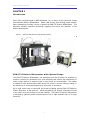
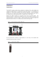
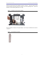
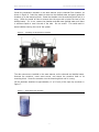
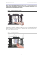
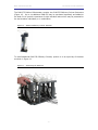
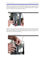
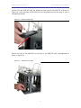
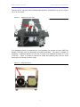
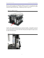
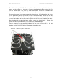
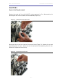
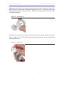
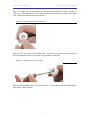
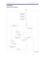
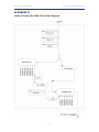
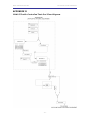
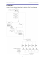
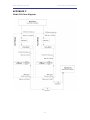
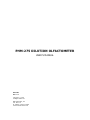
PHM-275 DILUTION OLFACTOMETER
USER’S MANUAL
DOC-007
Rev. 2.2
Copyright © 2007
All Rights Reserved
MED Associates, Inc.
P.O. Box 319
St. Albans, Vermont 05478
www.med-associates.com
MED ASSOCIATES INC.
DILUTION OLFACTOMETER
- ii -
MED ASSOCIATES INC.
DILUTION OLFACTOMETER
TABLE OF CONTENTS
Chapter 1 ...............................................................................................1
Introduction ......................................................................................................... 1
PHM-275 Dilution Olfactometer with Optional Pumps .............................................. 1
Chapter 2 ...............................................................................................2
Installation .......................................................................................................... 2
Chapter 3 .............................................................................................12
Septa Seal Replacement ...................................................................................... 12
Scent Installation or Replacement ...................................................................... 15
Chapter 4 .............................................................................................16
Operation .......................................................................................................... 16
Appendix A ...........................................................................................18
PHM-275 Flow Diagram........................................................................................ 18
Appendix B ...........................................................................................19
PHM-275 with Six PHM-276s Flow Diagram ............................................................. 19
Appendix c ...........................................................................................20
PHM-275 with Single Test Port Flow Diagram .......................................................... 20
Appendix D...........................................................................................21
PHM-275 with Controlled Test Port Flow Diagram .................................................... 21
Appendix E ...........................................................................................22
PHM-275 with Optional Manifold to Multiple Test Ports Diagram ................................ 22
Appendix F ...........................................................................................23
PHM-276 Flow Diagram........................................................................................ 23
- iii -
MED ASSOCIATES INC.
DILUTION OLFACTOMETER
- iv -
MED ASSOCIATES INC.
DILUTION OLFACTOMETER
CHAPTER 1
Introduction
Every effort has been made by MED Associates, Inc. to deliver a fully functional, tested
and calibrated Dilution Olfactometer. Please read through the following pages carefully
before attempting to unpack, set-up or operate the PHM-275 Dilution Olfactometer. This
document contains important information regarding the set-up and operation of the
Dilution Olfactometer.
Figure 1 – Dilution Olfactometer with Optional Pumps
PHM-275 Dilution Olfactometer with Optional Pumps
The PHM-275 Dilution Olfactometer is a standalone unit that provides the capability to
condition incoming air (desiccate, filter, and rehydrate) and controls the presentation of
either a single scent or a mixture of two or more scents to a test chamber. This system
is suitable for odor discrimination tasks where flow control is critical, olfactory coding, or
any behavioral or neurophysiological study using odor as a stimulus.
Up to eight scents may be controlled and mixed by adding optional PHM-276 Olfactory
Column Saturators to the base unit. Valves activated by 28 Volts DC solenoids are used
to mix odors and route airflow to the test chamber. The PHM-275 Dilution Olfactometer
is designed to generate precise concentrations of up to eight separate odors to a single
test point.
- 1 -
MED ASSOCIATES INC.
DILUTION OLFACTOMETER
CHAPTER 2
Installation
The PHM-275 system provides three containers to desiccate, filter, and rehydrate the
incoming air supply before it is mixed with the odor scent sources. The incoming air is
plumbed to a large central chamber that houses the desiccant. From the desiccant
chamber the air is routed to the chamber that contains activated charcoal filter, then to
the chamber that contains distilled water to rehydrate the air (see Figure 1).
Remove the smaller chambers by unscrewing them from the mounting block. The
desiccant container is removed by unscrewing two wing nuts located in the base of the
mounting structure, as shown in Figure 2. After the wing nuts are removed, support the
desiccant container while as it is lowered away from the mounting block.
Figure 2 - Remove Desiccant Container Wing Nuts
Fill the charcoal filter container to approximately ½” (12.5 mm) of its shoulder with
activated charcoal as shown in Figure 3.
Figure 3 – Charcoal Filter Chamber
- 2 -
MED ASSOCIATES INC.
DILUTION OLFACTOMETER
Install the filled charcoal filter chamber as shown in Figure 4. Insert the metal air tube
into the charcoal and gently guide the chamber up to the mounting block. Screw the
chamber into the mounting block until it is snug.
Figure 4 – Installing the Charcoal Filter Chamber
Fill the rehydration chamber with approximately 1” (25.4 mm) of distilled water as shown
in Figure 5.
Figure 5 – Filled Rehydration Chamber
- 3 -
MED ASSOCIATES INC.
DILUTION OLFACTOMETER
Install the rehydration chamber in the same manner as the charcoal filter chamber, as
shown in Figure 6. Insert the metal air tube into the distilled water and gently guide the
chamber up to the mounting block. Screw the chamber into the mounting block until it is
snug. Check the metal air tube to ensure that the open end is below the level of the
distilled water. If it is not, remove the chamber and add more distilled water until there
is sufficient liquid to cover the end of the tube. Do not overfill. This could result in
water bubbles entering the rest of the system.
Figure 6 – Installing the Rehydration Chamber
The odor sources are installed in the same manner as the charcoal and distilled water.
Unscrew the container, insert scent source, and secure the container back to its
mounting block. Screw the container into the mounting block until it is snug.
Fill the desiccant chamber to approximately ½” (12.5 mm) of the open top as shown in
Figure 7.
Figure 7 – Filled Desiccant Chamber
- 4 -
MED ASSOCIATES INC.
DILUTION OLFACTOMETER
Gently raise the desiccant around the central metal air tube as shown in Figure 8. As top
of the container approaches the mounting block, align the threaded rod with holes in the
mounting flange on the bottom of the container.
Figure 8 – Installing the Desiccant Container
Ensure that the top of the container is in the O-ring groove of the mounting block and
attach the wing nuts as shown in Figure 9. Tighten the wing nuts to insure proper seal.
Do not over tighten the wing nuts.
Figure 9 – Installing the Wing Nuts
- 5 -
MED ASSOCIATES INC.
DILUTION OLFACTOMETER
The PHM-275 Dilution Olfactometer contains two PHM-276 Olfactory Column Saturators
(Figure 10). Up to six additional PHM-276 may be purchased separately and added to
the base unit to provide a maximum of eight individual odors which may be presented to
the test chamber individually or in combination.
Figure 10 – PHM-276 Olfactory Column Saturator
To install additional PHM-276 Olfactory Columns, position it on an open bay of the base
as shown in Figure 11.
Figure 11 – Positioning the PHM-276
- 6 -
MED ASSOCIATES INC.
DILUTION OLFACTOMETER
Remove a port plug from the lower manifold and replace it with a barbed nipple fitting
(3/16” [4.7 mm] male to 1/8” [3.2 mm]-27 NPT nylon tube fitting). Connect the inlet of
the new PHM-276’s solenoid valve to the newly installed barb fitting with a length of
3/16” (4.7 mm) ID 5/16” (7.9 mm) OD Tygon tubing.
Figure 12 - PHM-276 Solenoid Valve
Remove a port plug from the upper manifold and replace it with a barbed nipple fitting
(3/16” [4.7 mm] male to 1/8” [3.2 mm]-27 NPT nylon tube fitting). Connect the top
outlet of the new PHM-276 to the newly installed barb fitting with a length of 3/16” (4.7
mm) ID 5/16” (7.9 mm) OD Tygon tubing.
Figure 13 - PHM-276 Upper Connection
- 7 -
MED ASSOCIATES INC.
DILUTION OLFACTOMETER
Position the new PHM-276 onto the aluminum guide pins of the PHM-275 as shown in
Figure 14. Push the body of the PHM-276 onto the guide pins until the body of pins is
completely enclosed.
Figure 14 - PHM-275 Guide Pins
Secure the base of the PHM-276 to the base of the PHM-275 with a thumbscrew as
shown in Figure 15.
Figure 15 - Thumbscrew to Base
- 8 -
MED ASSOCIATES INC.
DILUTION OLFACTOMETER
Connect the air inlet port above the desiccant container (indicated by an arrow in Figure
16) to an air source.
Figure 16 - PHM-275 Air Inlet Port
If an adequate source of pressurized air is not available, an optional air pump (MED Pat
Number PHM-280) may be purchased from MED Associates. The pump is capable of
producing a maximum airflow of 0.28 cfm (7.8 lpm) at a maximum pressure of 7 psig
(0.59 bar). Figure 17 shows an optional air pump and vacuum pump with an arrow
pointing out the outlet of the air pump.
Figure 17 - Pump Outlet Port
- 9 -
MED ASSOCIATES INC.
DILUTION OLFACTOMETER
With air flowing through the conditioning chambers, the flow for the bypass and scent
sources may be adjusted and set. The flow for the bypass air is controlled by the needle
valve at the base of the flow meter, indicated by an arrow in Figure 18.
Figure 18 - Bypass Air Control
The flow rate may be adjusted from 0 to 2.5 liter per minute. The bypass air may be
used as a non scented air flow through the test area so that the introduction of scent will
not be accompanied by the sound of air flow, thus giving the subject an auditory cue to
the start of the test session.
Figure 19 - Flow Meter
- 10 -
MED ASSOCIATES INC.
DILUTION OLFACTOMETER
The airflow through PHM-276 Olfactory Column Saturators is regulated in the same
manner as the bypass air. However a normally closed solenoid valve controls the flow
into the needle valve. This unit has been designed to connect to a standard MED
Associates connection panel (Smart Control or Passive).
If a connection panel is not used, connect the black wire to +28 Volts and the red wire to
28 Volt ground to operate the solenoid valve. To close the valve, remove the red wire
from the ground. To set the flow rate through each odor container, activate the solenoid
valve for that module and use the needle valve to set the flow rate using the flow meter.
Once the desired flow rate has been verified, close the solenoid valve. Repeat this
process for each column saturator to be used during the test session.
Connect output of the top manifold (indicated by an arrow in Figure 20) to the test
chamber and the PHM-275 Dilution Olfactometer is ready to use.
Figure 20 - PHM-275 Air/Odor Outlet Port
- 11 -
MED ASSOCIATES INC.
DILUTION OLFACTOMETER
CHAPTER 3
Septa Seal Replacement
Remove the scent vial from the PHM-276 column saturator by first disconnecting the
scent output line from the check valve and manifold (Figure 21).
Figure 21 – Disconnect Scent Output Line
Disconnect the air inlet line from the flow control valve (Figure 22). Remove the cap and
its plumbing from the vial. Remove the air inlet and scent outlet plumbing from the cap.
Remove the Septa seal from the cap.
Figure 22 – Disconnect Air Inlet Line
- 12 -
MED ASSOCIATES INC.
DILUTION OLFACTOMETER
Replace the old seal with a new seal by inserting it into the cap as shown in Figure 23.
Be sure that the silicone side of the seal is against the cap top. The silicone side is the
lighter colored and softer side of the seal. Replacement Septa seals may be purchased
from MED Associates.
Figure 23 – Seal Alignment
Replace the cap with the new seal onto the glass vial and gently tighten the cap as
shown in Figure 24. This will seat the seal and provide a support for the seal while the
tubes pierce the seal.
Figure 24 – Secure Cap
- 13 -
MED ASSOCIATES INC.
DILUTION OLFACTOMETER
Insert the scent out line (the shorter of the two tubes) through the seal as shown in
Figure 25. Note that the end of the tube is positioned as close as possible to the outer
ring. Gently push the tube through the seal.
Figure 25 – Positioning the Scent Outlet Tube
Insert the air inlet tube into the Septa seal. Position the tip of the tube opposite the
shorter tube and as close to the outer ring as possible (Figure 26).
Figure 26 – Positioning the Air Inlet Tube
Return the assembled scent vial to the position on the PHM-275 Dilution Olfactometer
from which it was removed.
- 14 -
MED ASSOCIATES INC.
DILUTION OLFACTOMETER
Scent Installation or Replacement
Remove the scent vial from the PHM-276 column saturator by first disconnecting the
scent output line from the check valve and manifold (Figure 21). Disconnect the air inlet
line from the flow control valve (Figure 22). Remove the vial from its support structure.
Remove the cap and its plumbing from the vial. Clean the vial and insert the desired
scent source. Replace the cap with its plumbing and tighten until snug. Return the vial
to its support structure and reconnect the fittings. Appendix F presents a flow diagram
of the PHM-276 column saturator and its interface connections with the PHM-275 Dilution
Olfactometer.
- 15 -
MED ASSOCIATES INC.
DILUTION OLFACTOMETER
CHAPTER 4
Operation
With the column saturators and bypass airflow set to the desired flow rates, activation of
a column saturator solenoid will allow air scented with that particular odor to travel to
the test chamber. If more than one column saturator solenoid is activated at the same
time, the odors from each will be mixed in the upper manifold and delivered to the test
chamber.
The flow diagram in Appendix A presents an overview of the operation of a PHM-275
Dilution Olfactometer. Air is conditioned by passing through a desiccant to remove
suspended water, then a charcoal filter to remove odors, and finally rehydrated with
distilled water. The conditioned airflow is then bifurcated to the bypass air flow meter
and the lower manifold (Manifold #1) on the assembly base. The bypass air flows into
the upper manifold (Manifold #2) of the PHM-275 assembly and continues on to the test
chamber. The bypass air may be used as a non-scented “background” air flow through
the test area so that the introduction of scent will not be accompanied by the sound of
air flow, thus giving the subject an auditory cue to the start of the test session.
However, it should be noted that the bypass airflow will dilute the concentration of odor
when introduced to the test chamber.
The flow of air from Manifold #1 proceeds to the normally closed solenoid valves of all
olfactory column saturators present on the PHM-275 base. The standard PHM-275
includes two PHM-276 column saturators. When a solenoid valve is activated, the
conditioned air flows through the flow meter, which is used to adjust the flow rate
through the odor storage container. From the flow meter, the air passes through the
odor source. The scented air then flows through a check valve and into Manifold #2. If
bypass air is flowing through manifold #2 when the scented air is present, it will mix with
and dilute the scented air. When both solenoid valves are open at the same time, the two
odors will mix with the bypass air in Manifold #2 and flow on to the test chamber.
Appendix B depicts a PHM-275 with six PHM-276 Olfactory Column Saturators. The basic
operational concept remains the same. Activation of a single solenoid valve will allow
that scent to be presented at the test chamber. The simultaneous activation of multiple
solenoid valves will allow the mixing of those odors in Manifold #2, with the resulting
combined odor being presented at the test chamber.
The setup of the test chamber is dictated by the researcher’s protocol. Appendix C
presents a basic test approach that employs a sniff port and scent extraction via the use
of an optional vacuum pump. If a vacuum source is not available, MED Associates offers
a small vacuum pump (MED part number PHM-281) that can provide a maximum airflow
of 0.25 cfm (7 lpm) at a maximum vacuum of 11 in. Hg (428 mbar). Contact Sales at
MED Associates for further details on available test chamber equipment and pumps.
If more sophisticated control of the flow at the test chamber, Appendix D presents an
optional test setup, which incorporates a three-way valve to control the flow into the test
port, and a needle valve controlled flow meter to control the flow to the vacuum pump.
- 16 -
MED ASSOCIATES INC.
DILUTION OLFACTOMETER
Appendix E presents another variation of application of the output from a PHM-275
Distillation Olfactometer. Here the odor is directed to a manifold that directs the scent to
the ports of a five-wall nose poke test chamber. The flow to the test ports is controlled
by solenoid valves that allowing the researcher to direct flow to individual ports or
multiple ports.
- 17 -
MED ASSOCIATES INC.
DILUTION OLFACTOMETER
APPENDIX A
PHM-275 Flow Diagram
- 18 -
MED ASSOCIATES INC.
DILUTION OLFACTOMETER
APPENDIX B
PHM-275 with Six PHM-276s Flow Diagram
- 19 -
MED ASSOCIATES INC.
DILUTION OLFACTOMETER
APPENDIX C
PHM-275 with Single Test Port Flow Diagram
- 20 -
MED ASSOCIATES INC.
DILUTION OLFACTOMETER
APPENDIX D
PHM-275 with Controlled Test Port Flow Diagram
- 21 -
MED ASSOCIATES INC.
DILUTION OLFACTOMETER
APPENDIX E
PHM-275 with Optional Manifold to Multiple Test Ports Diagram
- 22 -
MED ASSOCIATES INC.
DILUTION OLFACTOMETER
APPENDIX F
PHM-276 Flow Diagram
- 23 -