1
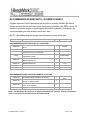
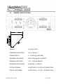
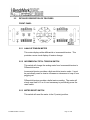
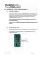
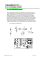
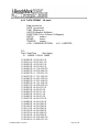
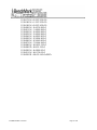
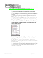
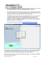
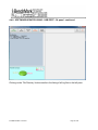
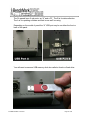
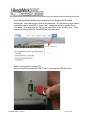
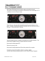
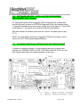
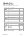
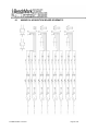
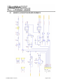
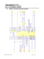
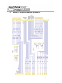
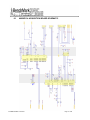
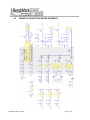
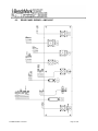
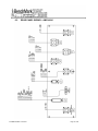
OPERATIONS AND MAINTENANCE MANUAL
WINCH OPERATORS PANEL
STANDARD CONFIGURATION
40 Series Panels
41 - 141 - 142 - 247
40 SERIES PANEL JAN 2015
Page 1 of 80
TABLE OF CONTENTS
___________________________________________
1.0
Quick Start Guide
2.0
Introduction
3.0
Menu Commands
4.0
Operation, Setup & Maintenance
5.0
BOM & Spares List
6.0
Drawings, Diagrams & Lists
7.0
Cables
40 SERIES PANEL JAN 2015
Page 2 of 80
Note - 3A Panel - The current version of this panel is
designated 3A because of its new computer main
board. Though the new panel is significantly improved,
the user interface and menus are mostly the same as
previous models.
4A Panel - All previous versions of this panel were
designated 4A. Any specific instructions in this manual
that refer ONLY to the 4A panels are highlighted with a
Green Background.
You can determine which panel you have by the Part
Number on the identification tag on the back of the
panel.
If your panel has a 3A in the part number, it’s a 3A
panel. If it has a 4A in the part number, it’s a 4A panel.
40 SERIES PANEL JAN 2015
Page 3 of 80
1.0 QUICK START PROCEDURES
1.1
Power up panel and verify it is working properly.
1.2
Verify the panel is configured to match the system (Acquisition System,
encoder, etc.)
1.3
Set up acquisition system.
1.4
Press T-Zero and verify that panel tension reads 0. Verify tension is
recorded on acquisition system.
1.5
Set line size to match cable size to be installed in head (refer to section 3).
1.6
Set Tension Alarm value (refer to section 3).
1.7
Set depth adjust value (refer to section 3).
1.8
Install cable in measuring head and lay it slack on the ground.
1.9
Press T-Zero to zero the tension value.
1.10
Press T-Test and verify that panel tension reads load pin shunt value.
Verify tension is being properly recorded on acquisition system.
1.11
Pull tool to depth 0 position. Press D-Zero and verify that panel depth reads
0. Set acquisition system depth to 0 at this time.
1.12
While logging, depth can be added or subtracted "on the fly by using the +/switch (refer to paragraph 2.1.11). When stationary, the +/- switch can be
used to preset the depth.
40 SERIES PANEL JAN 2015
Page 4 of 80
RECOMMENDED SPARE PARTS - 40 SERIES PANELS
All parts listed are Critical Spares and are required to properly maintain this device.
We recommend that all customers stock the quantity indicated in the ‘QTY’ column. IF
you are in a remote location or prefer having immediate availability of all spares, we
recommend that you stock at least one of each item.
NOTE – BenchMark may not always have all spares in stock all the time.
P/N
DESCRIPTION
QTY
REF
RECOMMENDED SPARE PARTS FOR ALL LOCATIONS
AMS4P020
AMS5P205
AMS4P044
40195
AMS5P191
AMS5P194
AMS5P192
AMS5P193
SWITCH SPDT TOGGLE LOCKING MTL-106D
ALCO
SWITCH SPDT TOGGLE ON-ON
SWITCH DPDT TOGGLE MOM OFF MOM
PANEL MOUNT C&K 7205SYZQE
1
POWER
1
INC/DIFF
1
+/-
SWITCH SPST PB NO MOM LIGHTED NKK
HB15SKW01-5C-CB
1
ALARM RESET
SWITCH SPDT MOM PUSHBUTTON NKK
MB2011SS1W01-RO
5
SWITCH DPDT MOM PUSHBUTTON NKK
MB2061SS1W01-RO
SWITCH CAP SCREW ON BLACK NKK AT407A
SWITCH CAP SCREW ON RED NKK AT407C
1
T-CAL
5
1
DEPTH ZERO
RECOMMENDED SPARE PARTS FOR REMOTE LOCATIONS
AM2KP134
PC BOARD AMS2K ACQUISITION BOARD
1
AMS4A154
METER 4" SHALLOW HSG CROMPTON DUAL
SCALE +/- 500KG 1000LB
1
AMS4P128
ACMU1P06
DISPLAY LED RED 0.5" 14 SEGMNT SERIAL 2"
x 3.5" 12 PIN HEADER
LED RED DIALIGHT 5V
3A PANELS
ONLY
4
1
METRIC
NOTE – PC Boards for 4A panels are no longer manufactured or available. Should a board failure
occur, a conversion kit and the new board can be ordered.
40 SERIES PANEL JAN 2015
Page 5 of 80
OBTAINING TECHNICAL ASSISTANCE
Call BenchMark Wireline Products Inc. at +1 281 346 4300
Or contact by email [email protected]
Or fax in request at +1 281 346 4301
Information in the form of user manuals and instructional videos are also available
on our website www.benchmarkwireline.com
Parts can be ordered by email, phone, or fax
Equipment can be returned for repair and maintenance. Please notify us by Phone,
email, or fax before sending any equipment.
To return equipment to BenchMark, ship it to:
BenchMark Wireline Products
36220 FM 1093
Simonton, Texas 77476
U.S.A.
40 SERIES PANEL JAN 2015
Page 6 of 80
2.0
INTRODUCTION
2.1
GENERAL DESCRIPTION
This panel is designed to acquire and display depth and tension data from a
wireline logging winch unit. The panel provides the operator a means to set
and make adjustments to the data as necessary.
Depth is displayed from data provided from an encoder mounted on a
measuring device. The encoder quadrature pulses are passed through to
the acquisition system. The tension data is provided by a load pin and is
also passed through to the acquisition system.
40 SERIES PANEL JAN 2015
Page 7 of 80
2.2
3A PANEL & NEW 2K BOARD
The new 3A version of the 247 panel contains a newly designed main processor
board designated the 2K Board. Because of advances in computer hardware,
several small boards on the legacy4A panel have been combined into a single more
efficient unit. The limited availability of replacement components on legacy panels
necessitated migrating to the newer more efficient design.
Additionally, the new 3A Panel offers several advantages:
2 USB Ports – software updates and data transfers are now simplified with these
input/output devices.
Internal Data Recorder –
Simplified Software Updates – Updates will be loaded on a thumb drive, inserted
into the proper USB port for downloading and by powering the board off then on,
the panel will automatically install updates.
Users will experience almost no difference in user interface, menu selections or
function between the new and legacy panels.
40 SERIES PANEL JAN 2015
Page 8 of 80
2.3
FEATURES
-
Digital displays for depth, line speed, tension and magnetic marks (or CCL
offset)
-
Analog incremental tension meter, 4 inch (108 mm) dia., 270 degree
-
Differential or Incremental tension zero push button switch
-
Excessive tension alarm setting allows operator to set tension alarm to a
predetermined value. Contact closure is provided for winch shutdown
-
Zero Depth button - sets depth to 0. Depressing button again resets depth to
previous setting. Can only be set when line speed is zero
-
Approaching surface alarm and shutdown.
-
Depth adjust up or down switches. Can only be set when winch is stopped
-
Load pin zero & calibrate controls.
-
Depth & tension saved in non-volatile memory at power loss
-
Outputs for Magnetic Marks, Tension and Encoder to interface to an acquisition
system.
-
RS232 Interface for additional control and data outputs
-
USB connectors for software upgrading and for log file downloading
-
Can be configured for any combination of FEET/METERS or POUNDS/KGS
-
Data Recorder with records both depth and tension data to a solid state memory
device
40 SERIES PANEL JAN 2015
Page 9 of 80
2.4
GENERAL SPECIFICATIONS
WEIGHT
5.5 LBS (2.5 KG)
TEMPERATURE RATING
-20 to 140 deg F
POWER SUPPLY
9 – 30 VDC @ 2 AMP MAX
MAXIMUM LINE SPEED
3000 FT/MIN @ 600 PULSES/FT
MINIMUM LINE SPEED
.6 FT (.18 M) per MINUTE
MAXIMUM LINE TENSION
25,000 LBS (11,340 KG)
DIGITAL TENSION
6 DIGITS WITH 1 LB OR 1KG RESOLUTION
DIGITAL LINE SPEED
6 DIGITS WITH .1 FT OR .1 M RESOLUTION
40 SERIES PANEL JAN 2015
Page 10 of 80
2.5
DETAILED DESCRIPTION OF FEATURES
FRONT PANEL
2.5.1 ANALOG TENSION METER
This meter displays either differential or incremental tension. This
provides a more visual display of tension change.
2.5.2 INCREMENTAL/TOTAL TENSION SWITCH
This switch will change the analog meter from Incremental tension to
Differential tension.
Incremental tension provides a high resolution tension scale. It must
be periodically reset as tension increases or decreases to keep it from
pegging out.
Differential tension provides a delta tension reading. The meter will
slowly reset itself to 0 so it is not necessary to periodically press the
reset switch.
2.5.3 METER RESET SWITCH
This switch will reset the meter to the 0 (center) position.
40 SERIES PANEL JAN 2015
Page 11 of 80
2.5.4 DEPTH DISPLAY
This meter provides a digital display of depth.
2.5.5 LINE TENSION DISPLAY
This meter provides a digital display of total line tension.
2.5.6 LINE SPEED DISPLAY
This meter provides a digital display of line speed.
2.5.7 MMD / CCL DEPTH DISPLAY
This meter provides a digital display of the CCL offset depth. This
depth can be set to provide a visual indication of the CCL depth in
addition to “bull-plug” depth.
If magnetic marks are used, this meter will display the depth of the
last mark detected.
2.5.8 MAGNETIC MARK RESET
Pressing the MMD reset button clears the last mark setting. The next
mark detected will be used to set the window for any subsequent
marks.
2.5.9 ZERO DEPTH
Pressing this button will reset the depth to 0. Depressing the button
again will reset the depth to the previous setting. The Zero Depth
button will only work when the line speed is zero (i.e. winch not
moving).
40 SERIES PANEL JAN 2015
Page 12 of 80
2.5.10 MENU
Pressing this button will activate the menu software. The software
feature to be set will be displayed on the DEPTH display. The
features can be toggled through by pressing the menu button until the
desired feature is displayed.
2.5.11 + / - SWITCH
This switch is used for different functions. It is used to change the
depth setting in either an up or down direction. The winch must be
stopped before the depth can be set. In menu mode (see section 3.0)
the switch is used to set menu parameters.
During logging this switch can also be used to add or subtract depth
while moving. Pressing the switch up one time will add .1 feet if in
feet mode or .1 meters if in metric mode. Pressing the switch down
will subtract depth (depth will be shallower).
The rate that the depth is added or subtracted is .1 foot per foot or .1
meter per meter.
If the switch is depressed longer, the amount of depth to add or
subtract will be increased. This amount to be added or subtracted will
be displayed on the depth display. Example – if you continue to hold
the switch until .5 is displayed, then .5 feet will be added over the next
5 feet.
40 SERIES PANEL JAN 2015
Page 13 of 80
2.5.12 ALARM RESET LED AND ALARM
This LED is lit and an audible alarm is sounded when the depth is less
than 200' (61 m) or whatever value the user has set. This provides a
warning to the hoist operator that they are approaching surface and
should take care to get the equipment safely out of the well. When
the LED is depressed, the alarm will stop but the LED will continue to
blink. Once the depth reading is greater than the set value, both the
alarm and the LED will turn off.
This switch also has a second function. In the event of an overtension
condition that sets the overtension relay, this button must be pressed
to reset the relay (refer to section 3.1).
This switch also resets the shutdown relay due to the depth shutdown
value as set by the operator.
2.5.13 ENGLISH / METRIC UNITS
These LEDs will indicate if the panel is in English (FEET) or metric
(METERS) mode. If the depth is set to English, the English LED will
be lit. If the depth is set to Metric the Metric LED will be lit. The
tension can be set to English (LBS) or Metric (KG) but it will not light
the LED.
2.5.14 T-ZERO SWITCH
Use this switch to set the tension to 0 at the start of a logging run.
This will zero out the tension circuit. The line should be slack through
the head at this time.
2.5.15 T-TEST SWITCH
Press T-TEST and verify that the panel tension reads 10000 lbs.
(4535 kg) for 5K and 5000 lbs. (2267 kg) for 3K. This can also be
used to verify tension is being properly recorded on acquisition
system.
2.5.16 USB CONNECTOR
Provides means to download data and set internal clock. Included in
later models plus modification for earlier models available.
40 SERIES PANEL JAN 2015
Page 14 of 80
2.6
REAR PANEL CONNECTIONS
NOTE – not all panels have all these connectors
Refer to Section 6.1 for Pin Out information.
2.6.1 12 – 24 VDC
This connector supplies dc power for the panel operation (9 VDC min,
30 VDC max). The panel can operate on either 12 or 24 vdc (12 vdc is
North American truck standard voltage, 24vdc is European truck
standard voltage). Pin A is positive, pin B is negative.
2.6.2 ENCODER 1 IN
+5 vdc power is provided to encoder 1 and signal is received from
encoder 1 on this connector.
2.6.3 ENCODER 2 IN
+5 vdc power is provided to encoder 2 and signal is received from
encoder 2 on this connector.
2.6.4 LOAD CELL IN
Load Cell excitation voltage is provided to the load pin and signal is
received from the load pin on this connector
2.6.5 MMD IN
DC power is provided to the magnetic mark detector and signal is
received from the mark detector on this connector.
40 SERIES PANEL JAN 2015
Page 15 of 80
2.6.6 RS232 SERIAL INTERFACE
This connector provides an RS232 interface from the panel to the
acquisition system. This provides a means to control the panel and
read data from the panel using a PC.
Refer to section 6 for details on using this port.
2.6.7 SIGNAL OUTPUT
Encoder, tension, and magnetic mark signals, processed and some
unprocessed are passed through this connector to the acquisition
system
2.6.8 OVER TENSION CONTACT
This connector provides a connection to the overtension circuit relay.
When an overtension condition is active, the two pins are connected
together. In normal position the two pins are open. This feature can
be used to interface to the winch unit control system to provide
automatic hoist shutdown when an overtension condition is reached.
2.6.9 USB ONLY ON 3A PANELS
USB-A and USB-B connectors available on panel for:
USB-A – upgrading panel software – Refer to section 4.10 thru 4.13
USB-B – copying the panel log file to a laptop – Refer to section 4.4.8
40 SERIES PANEL JAN 2015
Page 16 of 80
3.0 MENU COMMANDS
This panel has internal software which allows it to be set for various configurations.
To change the settings, press the MENU button. The feature to be set will be
displayed on the DEPTH display. Press the MENU button again until the feature
you want to set is displayed.
The parameters for each feature will be displayed on the LINE TENSION display.
Press the +/- switch to cycle through all the available parameters. When the value
you want to select is displayed, press the MENU button. ACCEPT will then be
displayed. Press + for yes, - for no.
Following is a listing of all the available settings.
Note: The options for the AM3K and the AM5K measuring heads are not identical.
Note: The panel can be configured for use with either the AM3K or AM5K
measuring head. On the new 3A panel the measuring head is selected within the
Menu Commands.
On the legacy 4A panel, this selection is made by moving the Jumpers on the main
board. See section 4.13.2 for instructions on moving the Jumpers. 4A panels have
software number 247008 and lower.
40 SERIES PANEL JAN 2015
Page 17 of 80
3.1
TENSION ALARM - AM3K & AM5K
When preset tension value is reached, alarm sounds and tension display
flashes value
Procedure:
Use +/- switch to set the tension alarm setting.
Indication:
TENALM will be displayed on the DEPTH display and the value
will be displayed on the TENSION display as it is being set.
Selection:
Each cable size will have a corresponding Tension Alarm
setting. Only the setting for the cable size selected (see menu
option 1) can be adjusted.
Default Values
3-16
7-32
1-4
9-32
5-16
3-8
7-16
15-32
.474
.474DG
.484
.492
.550
.650
Other
40 SERIES PANEL JAN 2015
1500
1500
2000
2400
2400
2400
2400
2400
2400
2400
2400
2400
2400
2400
2400
AM3K or AM5K
AM3K or AM5K
AM3K or AM5K
AM3K or AM5K
AM3K or AM5K
AM3K or AM5K
AM5K ONLY
AM5K ONLY
AM5K ONLY
AM5K ONLY
AM5K ONLY
AM5K ONLY
AM5K ONLY
AM5K ONLY
AM3K or AM5K
Page 18 of 80
3.2
DELTA TENSION ALARM - AM3K & AM5K
When the delta tension setting is reached the alarm sounds. In incremental
mode, you must periodically press meter reset or this alarm will sound when
the tension reaches the set value. In differential mode, the meter will reset
itself and the alarm will only sound on a quick change of tension. The Alarm
Reset switch must be pressed to reset the over tension relay.
Procedure:
Use +/- switch to set the Delta Tension setting.
Indication:
DTALRM will be displayed on the DEPTH display and the
value being set will be displayed on the TENSION display as it
is being adjusted.
40 SERIES PANEL JAN 2015
Page 19 of 80
3.3
TENSION SHUTDOWN - AM3K & AM5K
When value is reached, alarm sounds, tension display flashes value, and
tension contact closure switch is closed. This can be used to provide a
signal to automatically stop the winch.
Procedure:
Use +/- switch to set tension shutdown setting
Indication:
OVRTEN will be displayed on the DEPTH display and the value
will be displayed on the TENSION display as it is being set.
Selection:
Each cable size will have a corresponding Tension Alarm
setting. Only the setting for the cable size selected can be
adjusted.
Default Values
3-16
7-32
1-4
9-32
5-16
3-8
7-16
15-32
.474
.474DG
.484
.492
.550
OTHER
40 SERIES PANEL JAN 2015
2000
2000
2500
3000
3500
3500
3500
3500
3500
3500
3500
3500
3500
3500
AM3K or AM5K
AM3K or AM5K
AM3K or AM5K
AM3K or AM5K
AM3K or AM5K
AM3K or AM5K
AM5K ONLY
AM5K ONLY
AM5K ONLY
AM5K ONLY
AM5K ONLY
AM5K ONLY
AM5K ONLY
AM3K or AM5K
Page 20 of 80
3.4
CABLE SIZE - AM3K & AM5K
Cable size selection automatically sets load pin angle setting for the selected
cable size.
For AM3K heads, wheel size is also automatically set for the selected cable
size.
If ‘Other’ is selected, the Tension Coefficient (TENCOF) value needs to be
entered. This value is based on the bend angle of the cable over the tension
wheel. This value is empirically derived and must be furnished by the
measuring head manufacturer.
Procedure:
Use +/- switch to select cable size.
Indication:
CABLE will be displayed on the DEPTH display and the
selections will be displayed on the LINE TENSION display.
Cable Size Values available
3-16
AM3K or AM5K
7-32
AM3K or AM5K
1-4
AM3K or AM5K
9-32
AM3K or AM5K
5-16
AM3K or AM5K - Default for AM3K
3-8
AM3K or AM5K
7-16
AM5K only
15-32
AM5K only
.474 USE THIS SETTING W/ DEEP GROOVED WHEEL AM5K ONLY
.474DG
AM5K only
.484
AM5K only
.492
AM5K only
.550
AM5K only
.650
AM3K or AM5K
OTHER
AM3K or AM5K - DEFAULT VALUE .474 FOR AM5K
40 SERIES PANEL JAN 2015
Page 21 of 80
3.4
CABLE SIZE - AM3K & AM5K continued
HIGH TENSION (DEEP GROOVE) WHEEL
The .474DG and larger cable sizes designate the High Tension or
deep grooved tension wheel when installed on the AM5K measuring
head (refer to AM5K measuring head user manual). This wheel is
used for high tension operations or with cable requiring less bend. It
can only be used with .474DG or larger cables.
The other tension wheel available on the AM5K measuring head is a
shallow groove or flat wheel. This wheel will work with 15-32 and
smaller cable sizes.
OTHER
If you select the "OTHER" setting, you will be allowed to change the
measuring wheel circumference and the load cell factor. This allows
the panel to with a different type of measuring head or a different load
cell, such as a derrick mounted load cell.
When "OTHER" is selected, two additional inputs will be required:
CALVAL and WHLCIR.
This setting is for the load cell or load pin shunt value. The
default for the AM5K is 10,000 lbs and for the AM3K is 5,000
lbs.
WHLCIR (Wheel Circumference) This value is set to the
circumference of the measuring wheel to ensure the depth is
measured correctly. Default value is 2.0 ft.
TENCOF (Tension Coefficient) The TENCOF value can be
used to adjust the tension reading from the load cell or the load
pin. The range for cable ‘Other’ is +/- 0.2 and the range for all
other cable sizes is +/- 0.1. This equates to a tension factor of
+/- 20% (percent) and +/- 10% (percent), respectively.
40 SERIES PANEL JAN 2015
Page 22 of 80
3.5
DEPTH ADJUST (Shim) AM3K OR AM5K
The shim amount selected will automatically be added or subtracted from the
depth input.
Procedure:
Use +/- switch to set the shim setting.
Indication:
DP-ADJ will be displayed on the DEPTH display and the value
will be displayed on the TENSION display as it is being set.
The values are feet / thousand.
Default value is 0.
40 SERIES PANEL JAN 2015
Page 23 of 80
3.6
DEPTH ALARM AND SHUTDOWN - AM3K OR AM5K
1. When this value is set, it corresponds to the depth shutdown.
2. The depth alarm is automatically set to 25 feet deeper than the shutdown
value.
3. This alarm and shutdown activates when the panel depth is deeper than
the set values and the cable is moving uphole. This is known as
‘Approaching The Surface Alarm And Shutdown’.
4. When Alarm depth value is reached, the alarm will sound and LED will
flash. Pressing the LED switch will turn off alarm but the light will continue to
flash.
5. When shutdown depth value is reached, the alarm will sound again, the
LED will continue to flash and the shutdown relay will energize. Pressing the
LED switch will turn off the alarm and de-energize the shutdown relay but the
light will continue to flash.
6. Procedure: Use +/- switch to set the depth alarm value.
Indication:
40 SERIES PANEL JAN 2015
DPTHSD will be displayed on the DEPTH display and the value
will be displayed on the TENSION display as it is being set.
Default value is 200’
Page 24 of 80
3.7
MMD or CCL - AM5K ONLY
Either MMD or CCL can be selected. MMD provides a the ability to detect
magnetic marks. CCL provides a means to display the offset between the
CCL depth and the bull plug depth.
Procedure:
Use +/- switch to select either MMD or CCL.
3.7.1 CCL - AM3K OR AM5K
The CCL depth will be displayed on the MMD meter. This makes it
easier to monitor CCL depth in addition to bottom of tool depth. The
following menu options are available.
CCL OFFSET
The CCL depth will be displayed on the MMD meter. This
makes it easier to monitor CCL depth in addition to bottom of
tool depth.
Procedure:
Use +/- switch to set the CCL offset depth
Indication: CCL will be displayed on the DEPTH display and the
value will be displayed on the TENSION display as it is being
set.
OFFSET
Use +/- switch to set the CCL offset depth
LOG
The following menu options are available:
LOG CCL
Displays latest 100 collars. Will overwrite the oldest collar after
100.
CCL DLY
Use +/- switch to set delay from 1.0 to -0.1 Adds or subtracts
to detected collar depth.
CCL_BP
Turns detected CCL audio on or off.
40 SERIES PANEL JAN 2015
Page 25 of 80
3.7.1 CCL - AM3K OR AM5K continued
STRCOR (stretch correction) - AM3K OR AM5K
Use +/- switch to toggle between ON or OFF
When STRETCH Correction is on, the panel will automatically
correct depth to compensate for cable stretch. The following
information will then be requested:
TOOLWT - AM3K OR AM5K
The weight of the tool string at the end of the cable. Default
value is 1000 lbs.
FLUIDW- AM3K OR AM5K
The fluid weight of the well bore fluids. Default value is 8.3
lbs.
Stretch in the wireline is compensated in the following
manner:
As the tool is lowered into the well the depth traveled is measured
using the optical encoders 10 times a second. The tension is used
to “back out” the stretch on the wireline for that segment and a non
stretched depth is calculated by keeping a tally of all of the
segments. This summed value is used in the following manner to
calculate the depth:
If the tension is less than the calculated line weight the tool is
assumed to be floating or supported in some other manner. The
tension is due to the line weight so the stretch added is = summed
depth * tension * Ks * 1/2 where Ks is the stretch coefficient. If the
tension is greater than the line weight the stretch due to the line
weight is calculated as above and all other weight is assumed to be
acting over the entire length of the cable or = sum depth *((line
weight * ½) + (tension-line weight)) * Ks
CCL LOG
Press the +/- switch and you will be able to see the depth at
which each casing collar was detected. The MMD/CCL
display will display the depth of each collar when the switch is
pressed.
40 SERIES PANEL JAN 2015
Page 26 of 80
3.7.2 MMD - AM3K OR AM5K
The following menu options are available.
MMDCOR (MMD Correction)
Use +/- switch to toggle between ON or OFF
If MMD is set to ON the panel will automatically correct depth to
correspond to magnetic mark spacing. When depth is
automatically added or subtracted it will be done evenly at a
rate of 1’ per 10’.
STR CORR (Stretch Correction)
Stretch Correction works differently depending if MMD
correction is ON or OFF.
If MMD Correction is ON and STRCORR is ON, the panel will
automatically correct the MMD WINDOW depth to compensate
for cable stretch. The Mark Window will change as the cable
stretches to make sure the window is always set properly.
STRCORR can be turned off by selecting OFF. No stretch will
be added in this case.
If MMD Correction is OFF or STRCORR is off, no stretch will
be calculated.
If STRCORR is turned ON, the following information will be
requested:
TOOLWT - The weight of the tool string at the end of the cable.
Default value is 1000 lbs.
FLUIDW - The fluid weight of the well bore fluids. Default value
is 8.3 lbs.
SPACNG
This is to set the spacing at which the magnetic marks were
installed on the wireline.
Use +/- switch to toggle between 100, 25 M, 50 M.
40 SERIES PANEL JAN 2015
Page 27 of 80
WINDOW
The MMD window determines when the next mark can be
detected. The cable must travel at least the distance of the
mark spacing (100’, 50m or 25m) – the window setting, before
a mark can be detected. Marks can only be detected if they
occur within this window. If the window is set for 5' and the
mark spacing is 100’, the cable must travel no less than 95' and
no more than 105’ from the last mark before a new mark can
be detected.
The MMD Depth display will blink when the depth is within the
mark Window.
The Window is disabled after the MMD Reset button is pressed
and will not be enabled until the first mark is detected.
Procedure:
Use +/- switch to change MMD window value.
Indication:
MMD will be displayed on the DEPTH display and
the window value will be displayed on the
TENSION display as it is being set.
Pressing the MMD reset button clears the last
mark setting.
MMD LOG
The depth of the first 25 detected marks is stored in memory
and can be displayed.
40 SERIES PANEL JAN 2015
Procedure:
Use +/- switch to toggle through all of the marks
that have been detected. This starts from the last
mark detected. Pressing depth 0 will clear all the
stored marks.
Indication:
MMD DP will be displayed on the DEPTH display
and the mark depth will be displayed on the
TENSION display.
Page 28 of 80
3.8
ENCODER SELECT - AM3K OR AM5K
This function allows the user to change encoders by selecting
a different encoder connected to the panel.
Procedure:
Use +/- switch to select which encoder input on the rear panel
will be used.
Indication:
ENCSEL will be displayed on the DEPTH display and the
encoder selected appears on the Depth display.
a. ENC 1
b. ENC 2
c. BOTH - AM5K ONLY
If BOTH is selected, the depth will be a composite of ENC 1 or
2. The two encoders are compared 10 times per second and
the encoder that moves the furthest at each comparison will be
used to increment the composite depth.
Note: Encoder 1 will always turn the opposite direction from encoder 2. In
direct mode (see section 3.11), the encoder output will be in the same
direction as encoder 1.
3.9
ENCODER PULSES PER REVOLUTION - AM3K OR AM5K
The value selected will automatically be used as the encoder input pulses
per revolution (PPR) setting.
Procedure:
Use +/- switch to set the ENCODER Pulse Per Revolution
setting.
Indication:
ENCDOR will be displayed on the DEPTH display and the
value will be displayed on the TENSION display as it is being
set. Default value is 1200.
40 SERIES PANEL JAN 2015
Page 29 of 80
3.10
ENCODER DIRECTION- AM3K OR AM5K
The value selected will toggle the encoder direction between UP and Down.
3.11
Procedure:
Use +/- switch to set the ENCODER direction setting.
Indication:
ENCDIR will be displayed on the DEPTH display and either UP
or DN value will be displayed on the TENSION display.
Default value is UP.
ENCOUT - ENCODER PULSES OUT CORRECTED OR DIRECT - AM3K
OR AM5K
This setting determines whether the encoder output pulses reflect either
corrected depth or raw depth from encoder #1 only.
3.12
Procedure:
Use +/- switch to set mode.
Indication:
ENCOUT will be displayed on the DEPTH display and the
options: CORECT or DIRECT will be displayed on the
TENSION display.
NOTE:
Encoder #2 will not output pulses in DIRECT mode.
SYSTEM PULSES PER FOOT- AM3K OR AM5K
This setting determines the encoder pulse rate that will be output to the
acquisition system.
Procedure:
Use +/- switch to set the encoder output value.
Indication:
SYSPPF will be displayed on the DEPTH display and the value
will be displayed on the TENSION display as it is being set.
40 SERIES PANEL JAN 2015
Page 30 of 80
3.13
DEPTH UNITS - AM3K OR AM5K
The depth values will be displayed in the units selected.
3.14
Procedure:
Use +/- switch to set the DEPTH UNITS setting.
Indication:
DEPTH will be displayed on the DEPTH display. The selection
can be toggled between FEET or METERS. The selection will
be displayed on the TENSION display. The ENGLISH (green)
LED display will be lit when FEET is selected and the METRIC
(red) LED will be lit when METERS is selected.
TENSION UNITS - AM3K OR AM5K
The tension value will be displayed in the units selected.
Procedure:
Use +/- switch to set the TENSION UNITS setting.
Indication:
TENSION will be displayed on the DEPTH display. The
selection can be toggled between POUNDS and KILOGM. The
selection will be displayed on the TENSION display.
40 SERIES PANEL JAN 2015
Page 31 of 80
4.0 OPERATION, SETUP & MAINTENANCE
4.1
PROCESSOR REBOOT
In the event of a panel "lock up" or other malfunction, the processor in the
panel can be rebooted by turning off the panel, depressing the T-ZERO and
T-TEST buttons simultaneously then turning the power back on while the
buttons are depressed. Keep buttons the depressed for at least five
seconds after power is restored.
When the panel is rebooted, all the menu settings will be returned to the
factory default settings.
The panel should always be rebooted after new software (eprom) has been
installed.
4.2
DIGITAL DISPLAY SETUP
The four digital displays can be set for address, baud rate, and brightness
Three buttons are located on the rear of the display which are used to
change these settings.
40 SERIES PANEL JAN 2015
Page 32 of 80
The button nearest the connector selects the parameter (address, baud rate,
brightness).
The center button increments the parameter up
The end button increments the parameter down.
After the parameter is set, press the parameter button again to store it.
The addresses should be set as follows:
Line Tension = 1
Line Speed = 2
Depth = 3
MMD/CCL = 4
Set Baud Rate to 9600
Set Brightness to 15
Digital Display Pinout
PINS 1, 2, 7, 9
PINS 4, 6, 8, 10
PIN 3
PIN 5
40 SERIES PANEL JAN 2015
GND
+5 VDC
TXD
RXD
Page 33 of 80
4.3
CCL BOARD SETUP - 4A panel
To test the operation of the panel, adjust R3 on the CCL/Fuse board to
receive satisfactory collars if needed. The boards were set to a threshold
value of approximately +1.5V input to the CCL circuit during testing.
Setting the input to +1.5V would be a good starting point to set up the
circuit before installing the panel in a unit. CCW adjustments of R3 will
raise the threshold voltage required to acquire a CCL mark (less sensitive).
Example: If CCL marks are constant as the tools go down hole, adjust R3
CCW until CCL marks are on depth. Example #2: If no CCL marks are
found, turn R3 clockwise. An oscilloscope across CCL/Fuse board P2 pin
2 (signal) and 40 board TP1 (ground) will allow you to see the input signal
as you make your adjustments.
40 SERIES PANEL JAN 2015
Page 34 of 80
4.4
INTERNAL DATA RECORDER - 4A panel
This device records depth and tension data along with other job parameters
onto a compact flash card.
4.4.1 DATA FORMAT - 4A panel
Data is stored as:
DATE (yyyymmdd)
TIME (hhmmss.ss
UNITS (E=English, M=Metric)
DIRECTION (U=Up, D=Down, S=Stopped)
DEPTH
nnnnn.n
SPEED
nnnn.n
TENSION
nnnnnn
<CR> - CARRIAGE RETURN,
<LF> - LINEFEED
See following example
20091202
20091202
20091202
20091202
20091202
20091202
20091202
20091202
20091202
20091202
20091202
20091202
20091202
20091202
40 SERIES PANEL JAN 2015
151415.00 E S + 41.7 0.0 2317
151416.00 E S + 42.7 0.0 2317
151417.00 E S + 43.7 0.0 2317
151418.00 E S + 44.7 0.0 2317
151419.00 E S + 45.7 0.0 2317
151420.00 E S + 52.1 0.0 2317
151555.00 E S + 57.1 0.0 2317
151556.00 E S + 57.6 0.0 2317
151557.00 E S + 57.7 0.0 2317
151558.00 E S + 58.7 0.0 2317
151559.00 E S + 59.7 0.0 2317
151600.00 E S + 60.7 0.0 2317
151601.00 E S + 61.7 0.0 2317
151616.00 E S + 64.7 0.0 2317
Page 35 of 80
4.4.2 DATA FORMAT - 3A panel
Data is stored as:
DATE (yyyymmdd)
TIME (hhmmss.ss
UNITS (E=English, M=Metric)
DIRECTION (U=Up, D=Down, S=Stopped)
DEPTH
nnnnn.n
SPEED
nnnn.n
TENSION
nnnnnn
<CR> - CARRIAGE RETURN,
<LF> - LINEFEED
F10
File # Date/Time
Size (bytes)
10 14/09/05 11:38:06 28400
11:38:50 E S + 0.0 0.0 41 0 0
11:38:51 E U + 0.0 0.2 41 0 0
11:38:52 E S + 0.0 0.0 41 0 0
11:38:53 E S + 0.0 0.0 41 0 0
11:38:54 E D + 0.1 14.0 30 0 0
11:38:55 E D + 0.6 30.2 46 0 0
11:38:56 E D + 1.1 30.6 61 0 0
11:38:57 E D + 1.7 31.2 62 0 0
11:38:58 E D + 2.4 51.0 50 0 0
11:38:59 E D + 3.3 51.4 58 0 0
11:39:00 E D + 4.1 51.4 56 0 0
11:39:01 E D + 4.9 39.2 56 0 0
11:39:02 E S + 4.9 0.0 31 0 0
11:39:03 E S + 4.9 0.0 2 0 0
11:39:04 E D + 4.9 0.2 1 0 0
11:39:05 E S + 4.9 0.0 1 0 0
11:39:06 E S + 4.9 0.0 3 0 0
11:39:07 E S + 4.9 0.0 12 0 0
11:39:08 E S + 4.9 0.0 14 0 0
11:39:09 E S + 4.9 0.0 26 0 0
11:39:10 E S + 4.9 0.0 29 0 0
11:39:11 E S + 4.9 0.0 28 0 0
11:39:12 E S + 4.9 0.0 28 0 0
11:39:13 E U + 4.9 0.2 28 0 0
11:39:14 E S + 4.9 0.0 29 0 0
11:39:15 E U + 4.3 53.8 42 0 0
11:39:16 E U + 3.4 55.6 31 0 0
40 SERIES PANEL JAN 2015
Page 36 of 80
11:39:17 E U + 2.5 57.2 32 0 0
11:39:18 E U + 1.5 57.2 30 0 0
11:39:19 E U + 0.5 57.4 30 0 0
11:39:20 E U - 0.4 57.6 29 0 0
11:39:21 E U - 1.4 58.6 29 0 0
11:39:22 E U - 2.4 59.6 28 0 0
11:39:23 E U - 3.4 59.6 28 0 0
11:39:24 E U - 4.4 59.2 26 0 0
11:39:25 E U - 5.3 59.4 26 0 0
11:39:26 E U - 6.3 54.0 25 0 0
11:39:27 E U - 7.2 54.4 24 0 0
11:39:28 E U - 8.0 43.2 12 0 0
11:39:29 E D - 8.0 0.2 12 0 0
11:39:30 E U - 8.4 38.6 9 0 0
11:39:31 E U - 8.8 17.8 5 0 0
11:39:32 E S - 8.8 0.0 14 0 0 <EOF>
40 SERIES PANEL JAN 2015
Page 37 of 80
4.4.3 WELL NAME / UNIT NUMBER HEADER DATA - 4A panel
If a header containing information about the well, location, hoist unit
number, etc. is desired on the file, connect a PC to the USB connector
on the recorder face. When the directory is displayed right click the
mouse and choose new file. Enter the data you wish and save the file
as “unitdata.txt”. When the recorder board boots up it will look for the
file “unitdata.txt” and put whatever is in the file in the new file that will
record the data.
4.4.4 DATA RECORD - 4A panel
Data is written to the board 1 time per second. Data is stored in
ASCII TEXT format. Each line terminates with CR and LF characters.
To minimize the amount of data written to the board, the panel can be
set (see 3.1) to write data only when depth is changed by more than
0.1' or when tension changes by more than 10 pounds. Interpolation
can be used to fill in non written records since a DATE and TIME
stamp is recorded as a part of each data record.
The panel can also be set to write data continuously so that no
interpolation is necessary. This is recommend when if you want to
correlate surface depth and tension readings with memory gauge
readings.
The RECORD LED on the front of the DATA RECORDER board
indicates that it is in RECORD mode.
The DATA LED flashes each time a data record is written.
Before removing the CompactFlash card, turn the panel power off.
There is a delay when turning off the power while the data files are
being closed. After a short delay, the panel will power itself off.
To continue recording on a new flash card, insert the card then turn
the panel off then on. This will put the panel into record mode and
write a new header file on the CompactFlash card.
New File – created or power up
YYMMDDXX where XX=0 - 99
40 SERIES PANEL JAN 2015
Page 38 of 80
4.4.5 DATA EXPORT - 4A panel
Early model 40 Series panels did not have a data collection capability.
Log data was passed to the logging system with no data recording
taking pace.
Later models recorded date on an internal CompactFlash card. The
card could be accessed via an external slot on the panel. The
memory board can be removed and data moved onto a PC using a
standard CompactFlash Media Reader. The data can be imported
into programs such as MS Excel or MS Access.
To remove the compact flash card, Press the release button to eject
the flash card.
4.4.6 MEDIA CARD - 4A panel
The CompactFlash media device used in the data recorder may be
ordered using part number AMS4P232. Additionally it may be
acquired from any number of other retail sources. 2 GB is the
minimum recommended size.
40 SERIES PANEL JAN 2015
Page 39 of 80
4.4.7 SETTING DATA RECORDER TIME AND DATE - 4A panel
To change the time and date of the panel follow this procedure:
1. Turn the panel on and make sure there is a flash card plugged into
the panel.
2. Connect a PC to the panel using the USB program port on the
panel.
3. On the PC, in Windows Explorer you will see the panel shown as
an additional drive on the PC. Autoplay may show the card in the
panel and click ‘explore’.
4. Look for the file/folder ‘howtosettime’ and open it. Inside you will
see the file ‘datetime.txt’. Click on that file to open it. It will likely open
in either Microsoft Wordpad or Notepad. The file will look like this
without the red notations.
5. Following the pattern shown in the example above, change the
number on the ‘Top Line’ to provide the correct time and date
information.
6. When finished, save the updated text file as…’datetime.txt’.
Remember you are saving these changes to the flash card located in
the display panel.
7. Disconnect the USB cord from the panel, power the panel off then
on and the proper time and date will be loaded into the panel. It is
now ready to record data.
40 SERIES PANEL JAN 2015
Page 40 of 80
4.4.8 DATA EXPORT - LOG FILE - USING USB PORT - 3A Panel
The new 3A panels require a Log File Assistant program to help extract the log files
from the flash drive for use in Windows based software. Download this file from our
website onto the laptop that will extract the data from the panel.
The AMS3A panels have a USB connector labelled ‘DATA’ that can be connected
to a laptop computer USB port with a standard cable with type ‘A’ to type ‘B’
connectors. The laptop computer may require a “FTDI Virtual COM Port” driver
installation if it does not recognize the USB COM Port when the cable is plugged in
with power applied to the AMS3A panel.
This data file download is available at www.BenchMarkWireline.com/support
Upon program start the available laptop computer COM Ports are searched for availability.
If the COM Port button text reports that no connection is made, click on the button and
then pull down the COM Port # list box and choose the proper COM Port.
Note that the lower left pane displays the MicroSD card usage – this is where the AMS3A
panel’s Log Files are stored.
40 SERIES PANEL JAN 2015
Page 41 of 80
4.4.8 SOFTWARE UPDATES USING - USB PORT - 3A panel - continued
Clicking on the ‘File Directory’ button results in the listing of all log files in the left pane.
40 SERIES PANEL JAN 2015
Page 42 of 80
4.4.8 SOFTWARE UPDATES USING - USB PORT - 3A panel - continued
Clicking on the ‘Download Files’ button will open a new dialog window. A specific log file is
then chosen from the list box and the Operator has the option of saving the file in three
different file extension formats; and re-naming and re-locating the file using the ‘Browse’
button.
40 SERIES PANEL JAN 2015
Page 43 of 80
4.4.8 SOFTWARE UPDATES USING - USB PORT - 3A panel - continued
The content of the selected log file is displayed in the right pane.
Erase All Log Files Button: Clicking on this button will open a dialog box asking for
confirmation to erase all log files.
40 SERIES PANEL JAN 2015
Page 44 of 80
4.4.8 SOFTWARE UPDATES USING - USB PORT - 3A panel - continued
Clicking on the ‘Set Clock’ button will open a dialog that allows the Operator to set the
Date/Time clock to the current Date/Time or to any Date/Time desired.
40 SERIES PANEL JAN 2015
Page 45 of 80
4.4.8 SOFTWARE UPDATES USING - USB PORT - 3A panel - continued
Clicking on the ‘Help’ button results in the display of the log file related commands for
informational purposes only.
Exit Button: Clicking on the ‘Exit’ button will open a dialog box asking for confirmation to
exit the Log file Assistant program.
40 SERIES PANEL JAN 2015
Page 46 of 80
4.5
RS232 SERIAL INTERFACE – HELP - 4A panel
To connect the panel to a computer, connect a serial cable from the PC to J6 on the
rear of the panel. The wiring is as follows:
DB9 PIN OUT: 2 = TRANSMIT, 3 = RECEIVE,
5 = GROUND
Run a program such as MS Windows HyperTerm using the following parameters
BAUD
BITS
PARITY
STOP
38,400
8
N
1
Press H or ? to display the help screen
* * * AMS4AXXX Help Screen * * *
H,? - This screen.
D - Display units, direction, depth, speed, and tension.
L - Modify load cell angle (factor) Usage: L1.2
P - Modify encoder pulses/revolution. Usage: P600
V - Verify setup status.
W - Modify wheel size (line other) (feet) Usage: W4.0
Z - Preset depth.Usage: Z0.0 |_|--> New depth.
U - Modify units of measure UF(feet);UM(meters);UP(pounds);UK(kg)
A - Depth Alarm. Usage: A100 |_|--> Depth Alarm.
N - Line Size N0 7/32; N1 9/32; N2 5/16; N3 3/8;N4 7/16;
N5 15/32; N6 15/32HT; N7 SLAM N8 SLAMHT; N9 SSLAM
M - Tension Alarm. Usage: 'M2500' for 2500 pound alarm.
J - Depth Adjust. Usage: 'J-1' for -1 ft per 1000 feet
S - System PPF Usage: 'S125' for 125 PPFoot to system
B - Enter Mud Weight B12.3 lbs/gal
T - Enter Tool Weight T1000 lbs
k - Toggle stretch correction on/off
p - Display depth and stretch data
m - Use MMK Correction
40 SERIES PANEL JAN 2015
Page 47 of 80
4.6
RS232 SERIAL INTERFACE - HELP - 3A panel
To connect the panel to a computer, connect a serial cable from the PC to J6 on the
rear of the panel. The wiring is as follows:
DB9 PIN OUT: 2 = TRANSMIT, 3 = RECEIVE,
5 = GROUND
Run a program such as MS Windows HyperTerm using the following parameters
BAUD
BITS
PARITY
STOP
38,400
8
N
1
Press H or ? to display the help screen
* * * AMS3AXXX Help Screen * * *
H,? - This screen.
D - Display units, direction, depth, speed, and tension.
L - Modify load cell angle (factor) Usage: L1.2
P - Modify encoder pulses/revolution. Usage: P600
V - Status Verification
W - Modify wheel size (line other) (feet) Usage: W4.0
Z - Preset depth.Usage: Z0.0 |_|--> New depth.
U - Modify units UF (feet), UM (meters), UP (pounds), UK (kilograms)
A - Depth Alarm. Usage: A100 |_|--> Depth Alarm.
N - Line Size N0 9/32; N1 3/8; N2 7/16; N3 15/32; N4 SLAM; N5 SSLAM;
N6 OTHER
J - Depth Adjust. Usage: 'J-1' for -1 ft per 1000 feet
S - System PPF Usage: 'S125' for 125 PPFoot to system
k - Toggle stretch correction on/off
p - Display depth and stretch data
C - Toggle D string depth/ccl display
E - Erase all log file information.
F - Display log directory/file.
Directory Usage: F
File Usage: F0
Show all files.
File Usage: F12
Where 12 is the file number.
40 SERIES PANEL JAN 2015
Page 48 of 80
a - Display analog values.
C - Display/Modify clock.
Display Usage: C
Modify Usage: CYY/MM/DD hh:mm:ss
YY - Year (00-99)
MM - Month (01-12)
DD - Day (01-31)
hh - Hour (00-23)
mm - Minute (00-59)
ss - Second (00-59)
#n where n = 0-AMS3A041 1-AMS3A141 2-AMS3A142 3-AMS3A247
F
Log Directory
File # Date/Time
Size (bytes)
1 00/00/00 00:00:00 0
2 14/09/19 06:04:46 12630
2 File(s) 12656 bytes 1977601168 bytes free
C - 14/09/19 06:45:42
E - Log file(s) erased.
F - Log Directory
File # Date/Time
Size (bytes)
1 14/09/19 06:45:57 0
1 File(s) 0 bytes 1977613824 bytes free
F# - File # Date/Time
Size (bytes)
1 14/09/19 06:45:57 60
06:46:06 E S + 0.0 0.0 19953
06:46:16 E S + 0.0 0.0 19964<EOF>
40 SERIES PANEL JAN 2015
Page 49 of 80
4.7
RS232 SERIAL INTERFACE – VERIFICATION - 4A panel
Press V to display the Verification Screen
* * * AMS4A247 Setup Status * * *
Software revision
Line Size =
Depth Units =
Depth Units =
Depth alarm =
Tension alarm =
Tension shutdown =
Encoder PPR =
Depth Adjust =
Wheel Circumference =
Load Cell Angle Factor =
System Pulse per Foot =
Cable volume =
Cable weight =
Weight fluid =
Cable weight fluid =
Tool weight =
Stretch Corr is
MMK correction is
Line stretch tool =
40 SERIES PANEL JAN 2015
S4100.01
slam
Feet
Pounds
100 ft
2400 lbs
3500 lbs
1200
0.0
2.000 feet
1.00
600.0
2118 cubic inches per 1000 feet
1.0
8.300
1.000
1000
OFF
OFF
8.3
Page 50 of 80
4.8
RS232 SERIAL INTERFACE - VERIFICATION - 3A panel
* * * AMS3A247 Status Verification* * *
Software Revision 4100.24
Line Size =
.474
Depth Units =
Feet
Depth alarm =
200 ft
Tension Units =
Pounds
Tension alarm =
2400 lbs
Encoder PPR =
1200
Depth Adjust =
0.0
Wheel Circumference = 2.000 feet
Load Cell Angle Factor = 1.00
System Pulse per Foot = 600.0
H
40 SERIES PANEL JAN 2015
Page 51 of 80
4.9
RS232 SERIAL INTERFACE- DATA SCREEN - 4A panel & 3A panel
Press D to display the Data Screen
DATA STRING DESCRIPTION
12345678901234567890123456
U D Zddddd.d ssss.s tttttt<CR><LF>
WHERE:
U – UNITS (Depth,
Tension)
'E' - English, English,
'G' - English, Metric,
'M' - Metric, Metric,
'F' - Metric, English
D - DIRECTION
('U' - UP; 'D' - DOWN; 'S' - STOPPED)
Z - ZERO DEPTH REF. ('+' BELOW GROUND; '-' ABOVE GROUND)
d - DEPTH
s - LINE SPEED
t - TENSION
<CR> - CARRIAGE RETURN, <LF> - LINEFEED
40 SERIES PANEL JAN 2015
Page 52 of 80
4.10
SOFTWARE UPDATES - USING USB PORT - 3A panel
This procedure is for periodic software updates on Benchmark wireline display
panels. It pertains to 40 series, 50 series, and 60 series display panels with the
new 3A board.
You can easily tell if you have a 3A series panel by looking at the silver
identification tag on the panel. If there is a 3A in the part number it is a 3A panel.
If it has a 4A in the part number use the software update method described in the
manual for that panel.
3A panels contain a new generation computer board that simplifies the process of
software updates.
40 SERIES PANEL JAN 2015
Page 53 of 80
The 3A panels have 2 usb ports, an “A” and a “B”. The B is for data collection.
The A is for updating software and that is one we’ll be using.
Depending on the model of panel the “A” USB port may be on either the front or
back of the panel.
You will need a common USB memory stick also called a thumb or flash drive.
40 SERIES PANEL JAN 2015
Page 54 of 80
Go to the BenchMarkWireline.com website and then Support and Software
Downloads. Insert the memory stick in that computer. On the memory stick make a
new folder named “ams2000” in lower case. Locate the software update file for
your panel. Then download the file into the new folder on the memory stick. Then
rename the downloaded file “ams2000.hex” all lower case.
Make sure the panel is turned OFF.
On your panel then locate the USB “A” port…and plug the USB stick into it.
40 SERIES PANEL JAN 2015
Page 55 of 80
Now Power ON the panel and it will go through an automatic boot cycle.
Very quickly it will recognize the presence of the memory stick and will begin a 10-0
countdown on the Line Tension screen.
When it hits zero, the panel will automatically erase the current software on the
panel. It will also automatically upload the necessary files from the memory stick to
the panel. This may take up to 5 minutes.
When the update process is complete it will briefly show a PASS notification. This
means that the update process is complete and was successful.
Now power the display panel OFF.
Remove the memory stick.
Now power the display panel back ON and the update will be complete.
Periodically check the BenchMark website for software updates.
Use this same software update process for all 40, 50 and 60 series 3A panels.
40 SERIES PANEL JAN 2015
Page 56 of 80
4.11 SOFTWARE UPDATES - USING THE RS232 SERIAL PORT REPROGRAMMING CURRENT CHIP - 4A panel
PROCEDURE:
1. Transfer the new revision HEX file to a PC with a serial port or a USB to serial
adapter.
2. Turn power on to the Hoistman’s panel.
3. Connect your PC to the serial port at the rear of the panel.
4. Open a Hyperterminal session. Use the following settings:
Serial Port: COM1
Baud Rate: 57600
Data Bits: 8
Parity: None
Stop Bits: 1
Flow Control: None
5. Set the switches on the CPU PCB to PROGRAM mode as follows:
1 - AWAY FROM CPU
2 - AWAY FROM CPU
3 - TOWARD CPU
6. Open the Hyperterminal connection and then press the keyboard ENTER key.
The MicroController ROM Loader will respond with a banner and then a '>' prompt.
7. Type an uppercase 'K' and the ENTER key and the ROM Loader will Klean-erase
the Flash.
8. Type an uppercase 'L' and the ENTER key and the ROM Loader will wait to Load
a HEX file.
9. Pull down the Hyperterminal TRANSFER menu and choose: Send Text File. The
file browser will open, so ensure that the file filter is set to:
Files of type - All files (*.*) and then go to the C:\ root directory and choose the new
revision HEX file to transfer.
40 SERIES PANEL JAN 2015
Page 57 of 80
10. The ROM Loader will begin programming the Flash and will report a GOOD
status for the duration of the programming procedure as follows:
GGGGGGGGGGGGGGGGGGGGGGGGGGGGGGGGGGGGGGGGGGGGGGGGGGG
GGGGGGGGGGGGGGGGGGGGGGGGGGGGGGGGGGGGGGGGGGGGGGGGGGG
GGGGGGGGGGGGGGGGGGGGGGGGGGGGGGGGGGGGGGGGGGGGGGGGGGG
GGGGGGGGGGGGGGGGGGGGGGGGGGGGGGGGGGGGGGGGGGGGGGGGGGG
GGGGGGGGGGGGGGGGGGGGGGGGGGGGGGGGGGGGGGGGGGGGGGGGGGG
GGGGGGGGGGGGGGGGGGGGGGGGGGGGGGGGGGGGGGGGGGGGGGGGGGG
GGGGGGGGGGGGGGGGGGGGGGGGGGGGGGGGGGGGGGGGGGGGGGGGGGG
GGGGGGGGGGGGGGGGGGGGGGGGGGGGGGGGGGGGGGGGGGGGGGGGGGG
GGGGGGGGGGGGGGGGGGGGGGGGGGGGGGGGGGGGGGGGGGGGGGGGGGG
GGGGGGGGGGGGGGGGGGGGGGGGGGGGGGGGGGGGGGGGGGGGGGGGGGG
GGGGGGGGGGGGGGGGGGGGGGGGGGGGGGGGGGGGGGGGGGGGGGGGGGG
GGGGGGGGGGGGGGGGGGGGGGGGGGGGGGGGGGGGGGGGGGGGGGGGGGG
GGGGGGGGGGGGGGGGGGGGGGGGGGGGGGGGGGGGGGGGGGGGGGGGGGG
GGGGGGGGGGGGGGGGGGGGGGGGGGGG
11. After the ROM Loader is finished programming the Flash set the switches on
the CPU piggy-back PCB as follows:
1 - TOWARD CPU
2 - TOWARD CPU
3 - AWAY FROM CPU
12. To operate from an EPROM instead of the Micro-Controllers internal memory,
set the switches on the CPU piggy-back PCB as follows:
1 - TOWARD CPU
2 - TOWARD CPU
3 - TOWARD CPU
40 SERIES PANEL JAN 2015
Page 58 of 80
4.12 SOFTWARE UPDATES – INSTALLING PRE-PROGRAMMED
REPLACEMENT CHIP - 4A panel
For older panels without CPU piggyback PCB w/3 switches, the software that
controls this panel is stored in an EPROM Integrated Circuit (see drawing below).
To upgrade the software to a new version, simply remove the eprom I.C. and install
a new eprom I.C. (be careful not to bend the legs during installation).
After new software is installed, make sure and "reboot" the panel (refer to step
6.7.3).
NOTE: For newer panels with the cpu piggyback PCB with 3 switches,( refer to
section 6.8 and 7.2.22 programming procedures).
4.13
CHANGING ADDITIONAL SETTINGS WITH PROCESSOR BOARD
In addition to updating software, for older software that does not have menu
selections for TENSION, DEPTH, HEAD TYPE AND LOAD PIN TYPE, you can
also change these values by changing jumpers on the board.
40 SERIES PANEL JAN 2015
Page 59 of 80
Jumpers are used to select default depth and tension units as well as Head Type
and Load Pin type.. These units can also be set with the menu commands (see
section 3) but when the panel is rebooted, it will be reset to the Jumper settings.
DEPTH - Jumper J1 determines the depth units.
A shorting bar across J1 will set the units to meters
No shorting bar will set the units to feet.
TENSION - Jumper J2 determines the tension units
A shorting bar across J2 will set the units to Kilo Grams
No shorting bar will set the units to pounds.
HEAD TYPE - Jumper J3 determines the type of measuring head.
A shorting bar across J3 will configure the panel for an AM3K
No shorting bar will configure the panel for an AM5K.
LOAD PIN TYPE - Jumper J4 determines the type of load pin.
A shorting bar across J4 will configure the panel for a non
amplified non linearized load pin.
No shorting bar will configure the panel for an amplified and
linearized load pin.
40 SERIES PANEL JAN 2015
Page 60 of 80
5.0 BILL OF MATERIALS & SPARES PARTS
40 SERIES PANELS BILL OF MATERIALS
PART
AMS3A247
AM2KP134
SW-247012
AMS4A154
AMS4P128
ACMU1P06
AMS4P307
AMS7M002
AMS4P020
AMS5P205
AMS4P044
AMS7P068
AMS4P198
AMS4M076
F244889000
PART
C276P152
40195
AMS4P738
AMS5P191
DESCRIPTION
PANEL HOIST OPERATOR DISPLAY 2mV/V
NON AMP LOAD PIN USB
PC BOARD AMS2K ACQUISITION BOARD
SOFTWARE FOR 247 DEPTH PANEL
METER 4" SHALLOW HSG CROMPTON DUAL
SCALE +/- 500KG 1000LB
DISPLAY LED RED 0.5" 14 SEGMNT SERIAL 2"
x 3.5" 12 PIN HEADER
LED RED DIALIGHT 5V
SONALERT SC616N MALLORY 4-16V 6-22mA
BRACKET SONALERT MOUNTING
SWITCH SPDT TOGGLE LOCKING MTL-106D
ALCO
SWITCH SPDT TOGGLE ON-ON
SWITCH DPDT TOGGLE MOM OFF MOM
PANEL MOUNT C&K 7205SYZQE
SCREW JACK D-CONNECTOR KEYSTON E
7231
SPACER UNTHREADED RND NYLON #4 5/16L x
3/16 OD (100/PK)
WINDOW LED RECESSED SERIAL DCI
DISPLAY
HANDLE OVAL 1-1/2 X 3 AL
DESCRIPTION
LED GREEN DIALIGHT 12V
SWITCH SPST PB NO MOM LIGHTED NKK
HB15SKW01-5C-CB
DUSTCAP PLUG CAPUSB-A
SWITCH SPDT MOM PUSHBUTTON NKK
MB2011SS1W01-RO
QTY
REF
1
1
1
4
1
1
1
METRIC
1
POWER
1
INC/DIFF
1
+/-
4
16
4
2
205090-1
QTY
1
REF
ENGLISH
1
ALARM RESET
1
102398-4
5
1
T-CAL
AMS5P192
AMS5P193
AMS4P139
SWITCH DPDT MOM PUSHBUTTON NKK
MB2061SS1W01-RO
SWITCH CAP SCREW ON BLACK NKK AT407A
SWITCH CAP SCREW ON RED NKK AT407C
CABLE ASSY USB TYPE A TO B 3 METERS
5
1
1
DEPTH ZERO
AMS5P225
DUSTCAP PLUG CAPUSB-B
1
USB CONN
DUST CAP
AMS5P194
40 SERIES PANEL JAN 2015
Page 61 of 80
RECOMMENDED SPARE PARTS - 40 SERIES PANELS
All parts listed are Critical Spares and are required to properly maintain this device.
We recommend that all customers stock the quantity indicated in the ‘QTY’ column. IF
you are in a remote location or prefer having immediate availability of all spares, we
recommend that you stock at least one of each item.
NOTE – BenchMark may not always have all spares in stock all the time.
6.0
P/N
DESCRIPTION
QTY
REF
RECOMMENDED SPARE PARTS FOR ALL LOCATIONS
AMS4P020
AMS5P205
AMS4P044
40195
AMS5P191
AMS5P194
AMS5P192
AMS5P193
SWITCH SPDT TOGGLE LOCKING MTL-106D
ALCO
SWITCH SPDT TOGGLE ON-ON
SWITCH DPDT TOGGLE MOM OFF MOM
PANEL MOUNT C&K 7205SYZQE
1
POWER
1
INC/DIFF
1
+/-
SWITCH SPST PB NO MOM LIGHTED NKK
HB15SKW01-5C-CB
1
ALARM RESET
SWITCH SPDT MOM PUSHBUTTON NKK
MB2011SS1W01-RO
5
SWITCH DPDT MOM PUSHBUTTON NKK
MB2061SS1W01-RO
SWITCH CAP SCREW ON BLACK NKK AT407A
SWITCH CAP SCREW ON RED NKK AT407C
1
T-CAL
5
1
DEPTH ZERO
RECOMMENDED SPARE PARTS FOR REMOTE LOCATIONS
AM2KP134
PC BOARD AMS2K ACQUISITION BOARD
1
AMS4A154
METER 4" SHALLOW HSG CROMPTON DUAL
SCALE +/- 500KG 1000LB
1
AMS4P128
ACMU1P06
DISPLAY LED RED 0.5" 14 SEGMNT SERIAL 2"
x 3.5" 12 PIN HEADER
LED RED DIALIGHT 5V
3A PANELS
ONLY
4
1
METRIC
NOTE – PC Boards for 4A panels are no longer manufactured or available. Should a board failure
occur, a conversion kit and the new board can be ordered.
40 SERIES PANEL JAN 2015
Page 62 of 80
6.0 DRAWINGS, DIAGRAMS & LISTS
6.1
AM2KP134 ACQUISITION BOARD SCHEMATIC
40 SERIES PANEL JAN 2015
Page 63 of 80
6.1
AM2KP134 ACQUISITION BOARD SCHEMATIC
40 SERIES PANEL JAN 2015
Page 64 of 80
6.1
AM2KP134 ACQUISITION BOARD SCHEMATIC
40 SERIES PANEL JAN 2015
Page 65 of 80
6.1
AM2KP134 ACQUISITION BOARD SCHEMATIC
40 SERIES PANEL JAN 2015
Page 66 of 80
6.1
AM2KP134 ACQUISITION BOARD SCHEMATIC
40 SERIES PANEL JAN 2015
Page 67 of 80
6.1
AM2KP134 ACQUISITION BOARD SCHEMATIC
40 SERIES PANEL JAN 2015
Page 68 of 80
6.1
AM2KP134 ACQUISITION BOARD SCHEMATIC
40 SERIES PANEL JAN 2015
Page 69 of 80
6.1
AM2KP134 ACQUISITION BOARD SCHEMATIC
40 SERIES PANEL JAN 2015
Page 70 of 80
6.1
AM2KP134 ACQUISITION BOARD SCHEMATIC
40 SERIES PANEL JAN 2015
Page 71 of 80
6.1
AM2KP134 ACQUISITION BOARD SCHEMATIC
40 SERIES PANEL JAN 2015
Page 72 of 80
6.2
REAR PANEL WIRING – AMS3A247
40 SERIES PANEL JAN 2015
Page 73 of 80
6.2
REAR PANEL WIRING – AMS3A041
40 SERIES PANEL JAN 2015
Page 74 of 80
6.2
REAR PANEL WIRING – AMS3A141
40 SERIES PANEL JAN 2015
Page 75 of 80
6.2
REAR PANEL WIRING – AMS3A142
40 SERIES PANEL JAN 2015
Page 76 of 80
6.3
INTERNAL WIRING LIST
NOTE – For technical assistance, please make inquiries below:
.
OBTAINING TECHNICAL ASSISTANCE
Call BenchMark Wireline Products Inc. at +1 281 346 4300
Or contact by email [email protected]
Or fax in request at +1 281 346 4301
Information in the form of user manuals and instructional videos are also available
on our website www.benchmarkwireline.com
Parts can be ordered by email, phone, or fax
Equipment can be returned for repair and maintenance. Please notify us by Phone,
email, or fax before sending any equipment.
To return equipment to BenchMark, ship it to:
BenchMark Wireline Products
36220 FM 1093
Simonton, Texas 77476
U.S.A.
40 SERIES PANEL JAN 2015
Page 77 of 80
6.4
FUSE BOARD - 4A panel
AMS4A686
Refer to 6.3 for wirelist
6.5
ENCODER PULLUP BOARD - 4A panel
40 SERIES PANEL JAN 2015
Page 78 of 80
7.0 CABLES
NOTE – View equipment system diagrams to identify the specific cable desired.
For technical questions, please make inquiries below:
OBTAINING TECHNICAL ASSISTANCE
Call BenchMark Wireline Products Inc. at +1 281 346 4300
Or contact by email [email protected]
Or fax in request at +1 281 346 4301
Information in the form of user manuals and instructional videos are also available
on our website www.benchmarkwireline.com
Parts can be ordered by email, phone, or fax
Equipment can be returned for repair and maintenance. Please notify us by Phone,
email, or fax before sending any equipment.
To return equipment to BenchMark, ship it to:
BenchMark Wireline Products
36220 FM 1093
Simonton, Texas 77476
U.S.A.
40 SERIES PANEL JAN 2015
Page 79 of 80
7.1
247 SYSTEM DIAGRAM
40 SERIES PANEL JAN 2015
Page 80 of 80