1
Microprocessors Lab Manual
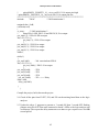
while (1){
led(ledd); // Directive led(0,1)
ledd = ~ledd; // ~ --->> complement
for(i=0;i<k;i++)
{
ledd=ledd; // wasting time or delay
}
delay_ms1(10); // or you can use delay_ms(1000)
}
}
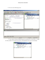
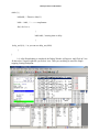
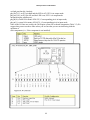
1.8. After Downloading is completed, the Debug Window will appear. And Click on View
Æ then select Target Peripherals you wish to view. Then you can debug as usual like Single
stepping, Setting breakpoint
40


![E^YB?= ce``_bd VY\Uc V_b @QbQTYW] 4UReW BD](http://vs1.manualzilla.com/store/data/005839928_1-81490c34e940fa2480ecad1c81f1b8b0-150x150.png)