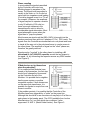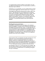
1
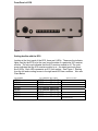
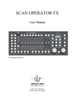
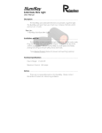
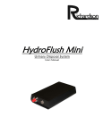
RICHARDSON
PRODUCTS
INCORPORATED
ECS - Environmental Control System
User’s Manual
ECS
Environmental Control System
Patent Pending
Warning:
This device should never be connected to any type of medical or life support system.
Copyright 2004 Richardson Products Incorporated.
9408 Gulf Stream Road Frankfort, Illinois 60423
Internet Address: WWW.RICHARDSONPRODUCTS.COM
Email Address: [email protected]
Some Don'ts
DON'T Use a Wall Switch Module to control a Fluorescent light, a
fan, or any kind of appliance. This could cause damage to the
Module and/or the light/appliance. (Do - get Appliance modules for
appliances.)
DON'T Use a Wall Switch Module to control an outlet unless you
are sure no one will plug an appliance ( a vacuum cleaner for
example) into the outlet. See above.
DON'T Use a Lamp Module to control a fluorescent light, a fan, or
any kind of appliance.
DON'T Use a Lamp Module or a Wall Switch Module to control a
lamp or fixture which already has a dimmer on it. (3-way OK if not
over 300 watts)
DON'T Use a module to control something which would be
dangerous if it were turned on remotely while unattended (e.g. an
empty coffee pot, an electric fan with poorly protected blades, or a
space heater.)
DON'T use a Wall Switch Module for lamps less than 60 watts.
DON'T leave a wireless intercom or baby monitor in the permanent
transmit (or talk) mode. Its transmissions could "block out" X10
transmissions.
DON'T exceed the rating of the modules, these are:
•
•
•
Lamp Module - 300 watts incandescent only.
Wall Switch Module - 500 watts incandescent only.
Appliance Module - appliances rated 15 amp. resistive (such
as coffee pots and heaters) or 1/3 H.P. motor load, or 400
watts for TV sets or 500 watts for lamps, because of the
"inrush current" from a cold lamp.
Introduction
Congratulations on your purchase of the Environmental Control System (ECS).
This product is manufactured from the highest quality electronic components
available. If you have purchased any of the option packages available for the
ECS, please refer to their instruction manuals for further assistance. Before
beginning the installation process please be sure you have received all of the
components. Identify all of the components and associated hardware that
comprise the ECS. Becoming familiar with the associated components will aid in
its installation. Remember to carefully follow the installation instructions in this
manual.
The Environmental Control System is an electronic device that interfaces with
your home or office existing electrical wiring via X10 Technology. The ECS
allows the user pushbutton or hands free voice recognition control of their lights
and appliances. There are 8 programmable X10 channels, which enable the
user to access an unlimited number of X10 receiver modules providing complete
control of their environment.
COMPONENTS
The ECS-100 system ships with the following components:
1 ECS Unit
1 9Volt DC wall adapter
1 PL513 Transmitter Module
1 PL513 line cord
Before you Begin
X10 is a communications "language" that allows compatible products to talk to each other using
the existing electrical wiring in the home. X10 compatible products talk over existing wires in your
home. Therefore, no costly rewiring is necessary. Installation of the ECS system is simple. The
ECS (Transmitter) plugs in at one location in the home and sends its control signals (on, off, dim,
bright, etc.) to a X10 receiver module which then controls the electrical appliance.
(Lamp,fan,radio)
110V
Electrical
Wires
ECS Base Unit X10 Factory Presets
The ECS is factory programmed with preset X10 commands. These settings are
internal and cannot be changed. It is required that all X10 receiver modules to
be used with the ECS have their ‘Housecode’ set to “A”.
ECS Base Unit User Programmable Features
The user only has to be concerned with training the Voice Recognition System
and setting the ’Unit Codes’ on all of the X10 receiver modules.
Lamp Modules
The ‘Lamp’ module is for use with anything that you can dim. This would be
lamps and various lighting fixtures.
The ‘lamp’ module has a rating of 120 Volts AC 60Hz., and a maximum of 300
watts.
Appliance Modules
The ‘Appliance’ module would be for items that you cannot dim. For example,
coffee maker, television set, stereo, ceiling fan, computer, any fluorescent
lighting, etc. The appliance module has a rating of 120 volts AC 60Hz.,
Resistive…..15A, Motor load…..1/3 HP., Incandescent lamp…..500W and
Television…..4000W.
You may purchase X-10 modules through Richardson Products Inc.
www.richardsonproducts.com/afdl.html#showcase
Front Panel of ECS
Figure 1
Getting familiar with the ECS
Looking at the front panel of the ECS, there are 8 LEDs. These are the indicator
lights used by the ECS to let the user know the state of a particular X10 receiver
module. The color red indicates that the X10 receiver module is off. The color
green indicates that the X10 receiver module is on. As stated previously there
are 8 LEDs. Each LED represents an X10 Unit number. See Figure 1, Starting
from the left and counting across to the right each LED has a number. Also see
Chart Below
LED NUMBER
LED#1
LED#2
LED#3
LED#4
LED#5
LED#6
LED#7
LED#8
X10 COMMAND UNIT CODE #
X10 Receiver Module #1
X10 Receiver Module #2
X10 Receiver Module #3
X10 Receiver Module #4
X10 Receiver Module #5
X10 Receiver Module #6
X10 Receiver Module #7
X10 Receiver Module #8
Special Functions
(Relay Control 1/8” Jack Located on
back panel of ECS)
Back Panel of the ECS
Figure 2
Located on the back of the ECS unit there are 5 push buttons.
From left to right they are:
Button Descriptions
#1-black
VOICE RECOGNITION SYSTEM RESET
#2-black
ECS MAIN RESET
Press the black pushbutton #2 This is the ‘X10 Reset’. At this time the ECS will
cycle through each of the 8 LEDs located on the front panel of the ECS unit.
These LEDs correspond to 8 X10 UNIT CODES. Pressing this button will
reboot the ECS and also shut off any item that is currently on and connected the
ECS.
#3-green
START VOICE RECOGNITION TRAINING
Press the green pushbutton #3 to start training the ECS voice recognition
features.
#4-white
#5-red
- Command Word Training
Be careful when both of the white and red pushbuttons are pushed together and
held for (3seconds) this will erase ALL of the voice recognition trained words.
Setting up the ECS
Step1
To install the ECS, begin by connecting one end of the PL513 line cord into the
PL513 module. (These plugs are polarized so they can’t be connected
improperly) Next connect the other end of the PL513 line cord into the back of
the ECS unit. Now plug the PL513 module into a110v wall outlet.
Step2
Plug the 9 volt DC wall adapter into a 110 volt wall outlet and then the other end
of the cord goes into the power jack on the back of the ECS unit.
Step3
Once the unit is plugged in, you will hear a beep followed by flashing red lights
(LEDs) located on the front panel of the unit.
Step4
Plug your test lamp into a wall outlet…MAKE SURE THE LAMP WILL LIGHT AS
SOON AS IT IS PLUGGED INTO THE WALL OUTLET! You have to ensure that
the lamp will light and that the local switch on the wall or the lamp is not blocking the
electricity going to the bulb!
For our examples used in this manual setup an X10 Lamp Module with a unit
code of 1. (Take a lamp module and turn the dial on the unit code switch until it
says 1.This will be the “desklamp” example used later in this manual) Plug a
lamp into the Lamp Module. Plug the Lamp Module into a live 110volt wall outlet.
You can setup another lamp module and turn the dial on the unit code switch
until it says 2 – this will be the “floorlamp” example used later in this manual.
Two Modes for Controlling the ECS
The ECS allows the user pushbutton or hands free voice recognition control of
their lights and appliances.
ECS PUSHBUTTON CONTROL
The ‘A’ and ‘B’ ports on the front of the unit are for pushbuttons access. (These
can be ordered directly from Richardson Products Inc. The red button plugs into
port ‘A’ and the blue button plugs into port ‘B’. These can be used in place of
using ‘trigger’ words. When the buttons are connected you are able to activate
any of the appliances by simply tapping the red button. After tapping the red
button you will see the LEDs begin to flash one at a time starting from the left and
going to the right. When the desired Macro lights up for the device that you want
to activate then tap the blue button. This will turn the chosen LED to green
indicating that the X10 device has been activated. Follow the same sequence to
turn off the X10 device.
ECS VOICE RECOGNITION CONTROL
The ECS can only be set up to recognize one voice. Before you can use the
voice recognition feature of the ECS, you will need to train it by using your voice.
Description of the ECS Voice Recognition System
The ECS has 15 Voice Commands that require a verbal command for proper
operation. The Commands are as follows:
Word 1 – Trigger Word - Command word 1 - your choice
Word 2 – Trigger Word - Command word 2 - your choice
Word 3 – Trigger Word - Command word 3 - your choice
Word 4 – Trigger Word - Command word 4 - your choice
Word 5 – Trigger Word - Command word 5 - your choice
Word 6 – Trigger Word - Command word 6 - your choice
Word 7 – Trigger Word - Command word 7 - your choice
Word 8 – Trigger Word - Command word 8 -your choice
Word 9 – Trigger Word - Command word 9 - ‘All Units Off’ function.
Word 10 – Trigger Word - Command word 10 - ‘All Units On’ function.
Word 11 -not used
Word 12 -not used
Word 13 – Trigger Word - Command word -Dimming function for a light.
Word 14 – Trigger Word - Command word -Brighten function for a light.
Word 15 -not used.
Note: All 15 channels require a verbal command.
Part of the ECS’s highly complex electronics and programming, it is required that
WORD # 11, 12, and 15 are not used but need a verbal command even though
you will not ever use them. This can be as simple as saying ‘No’ or ‘None’ when
prompted to give a verbal command for these Commands.
Special Channels
Command # 8 acts the same as 1-7 but is also specially set up for use with a
computer or any other relay activated device. The electronic relay circuit is built
into the ECS the output jack can be found on the back panel of the ECS. This
gives the user the ability to give a verbal command to control their computer or
any other relay activated device.
Command # 9 is used to turn all appliances off.
(SAY: ALL ON)
Command #10 is used to turn all appliances on.
(Say: ALL OFF)
Command #13 is used for dimming.
(Say: Dim)
Command #14 is used for brightening.
(Say: Brighten)
Remember you can use any words of your choice to program any command.
Voice Recognition Overview
Training the ECS is very simple. There are two types of words used to program
the voice recognition features of the ECS. There is a ‘trigger word’ and there are
the 15 ‘command’ words.
Example #1
The ‘trigger’ word is the word that makes the ECS listen for the command word.
For instance, you might decide to make your trigger word ‘Computer’. An
example voice command sequence would sound like this:
“Computer”…”Floorlamp” The trigger word “computer” gets the ECS
attention…then speaking the command word in this example “Floorlamp”…the
ECS would respond by turning on the floorlamp. To turn off the floorlamp you
would give the same command again. “Computer”…”Floorlamp”
Example #2
For instance, you might be fond of the name Bob and decide to make your trigger
word ‘Bob’. An example voice command sequence would sound like this:
“Bob”…”Floorlamp” The trigger word “Bob” gets the ECS attention…then
speaking the command word in this example “Floorlamp”…the ECS would
respond by turning on the floorlamp. To turn off the floorlamp you would give the
same command again. “Bob”…”Floorlamp”
ERASING VOICE RECOGNITION MEMORY
PLEASE NOTE: THE VOICE RECOGNITION MEMORY MUST BE ERASED
BEFORE PROGRAMMING CAN BEGIN. To erase the voice recognition
memory press the red and white buttons located on the back of the ECS at the
same time and hold for at least 3 seconds. Upon releasing these buttons the
memory of the Voice Recognition System will be erased. You will here the unit
say ‘Memory Erased’. The unit can now be trained.
PROGRAMMING THE ‘TRIGGER’ WORD
To program the ‘trigger’ word, press the green button on the back of the unit. You
will hear a ‘beep’ and the blue light will blink, you will hear ‘Please say word one’
say your trigger word now.
For example if your ‘trigger’ word is going to be ‘Computer’, the ECS will say
‘Please say word one’ you would then say ‘Computer’, it will then ask you to
repeat the ‘trigger’ word. You would again say the word ‘Computer’ again. The
unit will beep confirming that your ‘trigger’ word was successfully programmed.
We recommend following this example for now…once you become an expert using the
ECS you can reprogram the device anyway you like it. So for now try using the trigger
word “computer”. The trigger word is used to get the ECS systems attention. If you do
not speak loud enough, the unit will ask you to speak louder. When training the unit,
be sure to speak clearly and from an approximate distance that any future commands
will be given.
PROGRAMMING YOUR ‘COMMAND’ WORDS
The ECS is now ready to be programmed with your command words.
To train command words, push the red button on the back of the unit. The ECS
will respond by saying ‘Please say word one and then after you have given it a
command word for command # 1, the unit will ask you to repeat it again.
Prompting will continue through the rest of the programming. (Command Words
1-15) Remember that all 15 of the command words have to be programmed for
the ECS to work properly. Again, remember to speak clearly and from the
distance at which you will be giving it commands.
Word 1 Command word 1 “DESKLAMP” (Example say desklamp)
Word 2 Command word 2 – “FLOORLAMP” (Example say floorlamp)
Word 3 Command word 3 - your choice Use your imagination and make up a word for command word 3,4,5,6,7,8
Word 4 Command word 4 - your choice
Word 5 Command word 5 - your choice
Word 6 Command word 6 - your choice
Word 7 Command word 7 - your choice
Word 8 Command word 8 -your choice
Word 9 Command word 9 - ‘All Units Off’ function. (Example say “All Units off”)
Word 10 Command word 10 - ‘All Units On’ function. (Example say “All Units on”)
Word 11 -not used- but you still need to say something here (say anything it doesn’t matter)
Word 12 -not used- but you still need to say something here (say anything it doesn’t matter)
Word 13 – Trigger Word - Command word -Dimming function for a light. (Example say “dim”)
Word 14 – Trigger Word - Command word -Brighten function for a light. (Example say “brighten”)
Word 15 -not used- but you still need to say something here (say anything it doesn’t matter)
Note: All 15 channels require a verbal command.
Part of the ECS’s highly complex electronics and programming, it is required that
WORD # 11, 12, and 15 are not used but need a verbal command even though
you will not ever use them. This can be as simple as saying ‘No’ or ‘None’ when
prompted to give a verbal command for these Commands.
Please Note: You have to press the Main Reset Button #1 located on the
back panel of the ECS for the voice recognition system to start working.
After programming is complete and after you have pressed the voice recognition
reset button, the blue led will light, the ECS is now listening for your first
command. Say the trigger word the ECS should beep once…letting you know
that it recognized the trigger. Now give it the command word used in the
example “desklamp”. The X10 lamp module should light.
Say “Computer” …”Desklamp” the lamp lights.
Give the command again and the lamp will shut off. (The ECS toggles each device…so if
the lamp was on…then next time a command it will turn off…if the device was off …it
will turn the device on.)
DIM AND BRIGHTEN COMMANDS
Commands #’s 13 and 14 are for the dimming and brightening function for every
light that is used with this unit. You can simply use a command of ‘Dim’ for
Command #13 and ‘Brighten’ for Command# 14 to dim each light that is used
with the ECS unit. These commands cannot be changed by the user…they have
to be on channels 13 and 14 only.
To Dim and Brighten lamps. You have to tell the ECS which lamp you want by
first selecting the device then issuing the dim and brighten commands.
Try the following:
Say “Computer” …”Desklamp” the lamp lights.
Say “Computer”… “Dim” The lamp dims 25%
Say “Computer”…”Dim” The lamp dims an additional 25% (Lamp now at 50%)
Say “Computer”…”Dim” The lamp dims an additional 25% (Lamp now at 75%)
Say “Computer”…”Brighten” The lamp brightens 25%.
Say “Computer”…”Brighten” The lamp brightens an additional 25% etc.
Please Note: With each brighten or dim command the lights will change intensity
with each command you give. In other words, you can continue to give the
‘brighten’ or ‘dim’ command until you get the desired lighting effect you want.
Please note: You have to have some space between the trigger word and
the command word…About ½ a second. If you do not give your command
word within 3 seconds, after speaking the trigger word you will have to
repeat your trigger word and then give your ‘command’ word again.
IN THE EVENT OF A POWER FAILURE
In the event of a power failure the ECS unit will remember all of the trained
words. When the power is returned the ECS will reset and all connected
appliances will be shut off. You may have to reset the Voice Recognition Unit by
pressing the VR Reset button located on the back of the unit. Be sure to check if
the unit is listening by checking to see that the Blue Led located on the front
panel of the ECS is illuminated. This feature was designed into the unit for safety
reasons. The user will have to turn them back on by giving the ECS a trigger
word and a command word.
ADVANCED TROUBLE SHOOTING GUIDE
Please note the if the user experiences any of the following problems, they
should contact a certified electrician to make any of the following changes to their
household wiring.
Some Modules Don't Respond
The most commonly encountered problem with X10 systems that
use the existing house wiring to transmit signals is that some signals
are received by some Receiver modules, but not by others. For
example, the Controller controls some lights but not others or
controls some lights intermittently. This can happen sometimes
when the Module to be controlled is on the opposite phase of the
house wiring to the phase which the Controller is connected to. .
. Phases in household wiring is caused
by two different power currents running
from the electrical breaker box. (see
figure 1). It is, therefore, suggested
that the Controller and all Modules to
be controlled by that Controller be on
the same phase. This can be
accomplished by reviewing your
breaker panel (see figure 1 - "N" is
X10 units on "B" phase) Where it is not
possible, the problem can be solved
by fitting a coupling capacitor (also
known as a phase coupler or signal
bridge) across the two phases of the
house wiring to couple the signal from
one phase to the other. .
Phase coupling
In most cases the signals transmitted
by the Controller will control any
Module plugged in anywhere in the
house. The signal level transmitted is
usually in the order or 4 to 5 volts but
varies with line impedance and loading
(Controller plugged in next to a TV set,
for example.) However, the amplitude
of signal required to operate a module
is only 50 millivolts (0.05 volts) so
there is enough tolerance in the
transmit/receive ratio to allow for
considerable signal attenuation. Most
signal attenuation occurs when the
signal has to "jump the phases". .
Most houses are wired such that 220v (240V) is brought into the
breaker panel and then split into 2 phases of 110v ( 120V) each. The
signals from the Controller are transmitted onto one phase and have
to travel all the way out to the pole transformer to couple across to
the other phase. The amplitude of signal on the "other" phase can,
therefore, be greatly reduced.
Signals can be "coupled" to the other phase by installing a 0.1
microfarad (0.1µF), 600VDC capacitor across the two phases in
the panel, i.e. by connecting the capacitor across any 220V breaker
(see Figure 2) .
If Modules turn on by themselves
when they shouldn't:
If it is suspected that Modules have
turned on by themselves, the first step
should be to change the Housecode
on the Controller and all of the
Modules. It is possible that a neighbor
has the same system or another
compatible system. If both houses are
on the same pole transformer, it is
possible for signals to couple from one
house to another. .
If the problem persists, it is possible that the Controller of the
Modules have been triggered by a "spike" on the power line.
Although this should be a rare occurrence it may help to fit a filter on
each phase in the breaker panel, The 6276 (available from Leviton
Manufacturing Co.) is a filter which also contains a "spike
suppresser" or M.O.V. (Metal Oxide Varistor). See Figure 3.
It is suggested that a 6276 be installed on both phases, but if the
controller and all the Modules are on the same phase, one 6276 on
that phase may be sufficient.
If Modules turn on unpredictably, it is also possible that the modules
may have been triggered by a 120V AC power "dip" or "brown out".
Lamp Modules and Appliance Modules have a feature called "local
control". This feature lets you turn the Module on by turning the
power switch on the light or appliance off and then on again. There
is a circuit in the Module which detects this change in load and
interprets it as a request to turn on. This "local control" circuit by
design is very sensitive. Therefore it can sometimes change in the
load, and "think" it has been told to turn on. If this problem is
suspected, it is recommended that the local control feature be
disabled..
Disabling the local control feature
It is possible to disable the local control feature of the Appliance
Module by plugging a "cube tap" into the Module then two items can
be plugged into the same Module. Plug a 7 1/2 watt night light into
one of the receptacles of the cube tap and the appliance you want to
control into the other. When the Module is on, the appliance and
night light will be on. When the Module is off, the appliance and the
night light will be off. Now, even if you operate the power switch on
the appliance, the night light is always "in circuit" so the Appliance
Module's local control circuit is disabled.
Certain brands of TVs can generate noise and superimpose it on the
power line. In most cases, this kind of noise will not cause a
problem. If, however, it is determined that the TV is causing a
problem (which can be determined by unplugging the TV to see if
the problem goes away) it is suggested that the TV be plugged into a
filter to isolate it from the AC line. The kind of filter used to protect a
TV from interference from heavy applications like power drills is
recommended ( Cat.# 15-1111 from radio shack for example). This
filter may help to isolate the load (or internal capacitance) of the TV
from the AC line if it is found that the TV is attenuating the signals
from your Controller(s). .
Wireless Intercoms
Intercom systems which use the house wiring to transmit can "block
out" X10 transmissions while the intercom is left in the permanent
transmit (talk) mode. Unfortunately there is no simple solution to this
problem. If the Controller and all the Modules are on one phase the
first thing to try would be to change them all to the other phase. It
has been found that the 6276 filter can in some cases attenuate
signals from a neighbor's intercom sufficiently enough to allow the
Controller's signals to be received by the X10 Modules. It is NOT
possible to have a wireless intercom and a Controller operating in
the same house. Figure 3 shows how the 6276 should be
connected. .
Disclaimer
Richardson Products Incorporated shall not be held liable or assume any
responsibility for damage that may occur to the ECS or the electronic accessory
equipment intended to be powered from the ECS. If proper care is taken, the
ECS will provide a dependable way to control various appliances in your home
for many years.
RICHARDSON
PRODUCTS
INCORPORATED.
Copyright 2004 Richardson Products Incorporated.
9408 Gulf Stream Road Frankfort, Illinois 60423
Internet Address: WWW.RICHARDSONPRODUCTS.COM
Email Address: [email protected]
©2003 Richardson Products Incorporated.
Patent Pending