1
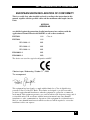
THE ACS335A KVM-EXTENDER FAMILY
Welcome to the ACS335A KVM-Extender
Family!
Thank you for purchasing a ACS335A KVM-Extender model. We appreciate your business,
and we think you’ll appreciate the many ways that your enhanced keyboard/video/ mouse
system will save you money, time, and effort.
That’s because our ACS335A KVM-Extender not only allows you to remotely locate a
console (Monitor, Keyboard, Mouse + optional serial/audio devices) over great distances
without any loss in signal quality (up to 1000m/3250ft) but also to do this in an EMI
hazardous environment.
Wherever you have great distances: airports, roller plants, distributed data centres; or in a
range of applications where you have large electromagnetic generators or loads, magnetic
resonance tomographs, induction furnaces, current generators; the ACS335A KVM-Extender
is a solution for remotely locating your console. Two different models cover a range of
applications: a KVM extender for a standard remote console – Monitor, Keyboard and
Mouse; and a second unit with KVM extension and additional serial and bi-directional audio
support. This device is also suitable for computers equipped with a serial mouse or touch
screen.
This manual will tell you all about your new ACS335A KVM-Extender, including how to
install, operate, and troubleshoot it. For an introduction to the Extender,
see Chapter 2. The Extender product codes covered in this manual are:
ACS335A: KVM-Extender for VGA, PS2-Keyboard/Mouse
ACS335A-AS: KVM-Extender for VGA, PS2-Keyboard/Mouse + Serial/Audio
1
ACS335A –5 STRAND KVM-EXTENDER
Copyrights and Trademarks
©2006. All rights reserved. This information may not be reproduced in any manner without
the prior written consent of the manufacturer.
Information in this document is subject to change without notice and the manufacturer shall
not be liable for any direct, indirect, special, incidental or consequential damages in
connection with the use of this material.
All trademark and trade names mentioned in this document are acknowledged to be the
property of their respective owners.
Disclaimer
While every precaution has been taken in the preparation of this manual, the manufacturer
assumes no responsibility for errors or omissions. Neither does the manufacturer assume any
liability for damages resulting from the use of the information contained herein. The
manufacturer reserves the right to change the specifications, functions, or circuitry of the
product without notice.
The manufacturer cannot accept liability for damage due to misuse of the product or due to
any other circumstances outside the manufacturer’s control (whether environmental or
installation related). The manufacturer shall not be responsible for any loss, damage, or injury
arising directly, indirectly, or consequently from the use of this product.
Cautions and Notes
The following symbols are used in this guide:
CAUTION. This indicates an important operating instruction
that should be followed to avoid any potential damage to
hardware or property, loss of data, or personal injury.
NOTE. This indicates important information to help you make the best use
of this product.
2
FCC/CDC STATEMENTS
FEDERAL COMMUNICATIONS COMMISSION
AND CANADIAN DEPARTMENT OF COMMUNICATIONS
RADIO-FREQUENCY INTERFERENCE STATEMENTS
This equipment generates, uses, and can radiate radio-frequency energy, and if not installed
and used properly, that is, in strict accordance with the manufacturer’s instructions, may
cause interference to radio communication. It has been tested and found to comply with the
limits for a Class A computing device in accordance with the specifications in Subpart B of
Part 15 of FCC rules, which are designed to provide reasonable protection against such
interference when the equipment is operated in a commercial environment. Operation of this
equipment in a residential area is likely to cause interference, in which case the user at his
own expense will be required to take whatever measures may be necessary to correct the
interference.
Changes or modifications not expressly approved by the party responsible for compliance
could void the user’s authority to operate the equipment.
Shielded PC-equipment cables must be used with this equipment to maintain compliance with
radio frequency energy emission regulations and ensure a suitably high level of immunity to
electromagnetic disturbances.
This digital apparatus does not exceed the Class A limits for radio noise emission from digital
apparatus set out in the Radio Interference Regulation of the Canadian Department of
Communications.
Le présent appareil numérique n’émet pas de bruits radioélectriques dépassant les limites
applicables aux appareils numériques de la classe A prescrites dans le Règlement sur le
brouillage radioélectrique publié par le Ministerié des Communications du Canada.
3
EMPTY PAGE
4
CE - DECLARATION OF CONFORMITY
EUROPEAN UNION DECLARATION OF CONFORMITY
This is to certify that, when installed and used according to the instructions in this
manual, together with the specified cables and the maximum cable length <3m, the
Units:
ACS335A
ACS335A-AS
are shielded against the generation of radio interferences in accordance with the
application of Council Directive 89/336/EEC as well as these standards:
EN 55022:
1999
EN 55024:
1999
IEC 61000-4-2:
2001
IEC 61000-4-3:
2001
IEC 61000-4-4:
2001
EN 61000-3-2
2001
EN 61000-3-3
2002
Class A
The device was tested in a typical configuration with PC.
th
Oberteuringen, Wednesday, October 11 , 2006
The management
This equipment has been found to comply with the limits for a Class A digital device,
pursuant to Part 15 of the FCC Rules. These limits are designed to provide reasonable
protection against harmful interference when the equipment is operated in a commercial
environment. This equipment generates, uses, and can radiate radio frequency energy and, if
not installed and used in accordance with the instruction manual, may cause harmful
interference to radio communications. Operation of this equipment in a residential area is
likely to cause harmful interference in which case the user will be required to correct the
interference at his own expense.
5
SAFETY PRECAUTIONS AND INSTALLATION GUIDELINES
Safety Precautions and Installation Guidelines
To ensure reliable and safe long-term operation, please note the following installation
guidelines:
•
Only use in dry, indoor environments.
•
The Remote unit, Local unit and any power supplies can get warm. Do not locate them
in an enclosed space without any airflow.
•
Do not place a power supply directly on top of a unit.
•
Do not obstruct a unit’s ventilation holes.
To safeguard against personal injury and avoid possible
damage to equipment or property, please observe the
following:
6
•
Only use power supplies originally supplied with the
product or manufacturer-approved replacements. Do not
attempt to dismantle or repair any power supply. Do not
use a power supply if it appears to be defective or has a
damaged case.
•
Connect all power supplies to grounded outlets. In each
case, ensure that the ground connection is maintained
from the outlet socket through to the power supply’s AC
power input.
•
Do not attempt to modify or repair this product
QUICK SETUP
Contents
1. Quick Setup
8
2. Overview
9
2.1
2.2
2.3
2.4
2.5
2.6
Introduction
Glossary
Features
Product Range
Compatibility
How to Use This Guide
3. Installation
3.1
3.2
3.3
3.4
Package Contents
Interconnection Cable Requirements
System Setup
Diagnostic and Adjustments
4. Adjustments
4.1
4.2
4.3
Jumper Location in the Local Unit
Jumper Location in the Remote Unit
Customization
5. Monitor Setup
5.1
5.2
5.3
TFT Monitors
Hints for Pixel Clock and Pixel Phase
Manual Adjustment of Video Signals
9
9
11
12
13
14
15
15
16
17
21
25
26
27
27
30
32
33
34
6. Troubleshooting
35
Appendix A: Example Applications
36
Appendix B: 19” Rack Mount Options
38
Appendix C: Audio/Serial Upgrade
40
Appendix D: Technical Support
42
Appendix E: Specifications
43
Appendix I: Connectors
45
7
ACS335A –5 STRAND KVM-EXTENDER
1. Quick Setup
This section briefly describes how to install your KVM extender system and optimise the
video signals. Unless you are an experienced user, we recommend that you follow the full
procedures described in the rest of this manual.
Install System
1.
2.
3.
4.
Connect Remote unit to KVM.
Connect Local unit to CPU or switch.
Connect Local and Remote units with fibre interconnection cable.
Power up the system.
Wait until the dot lapses
YES
Is the dot on the
7 segment display
illuminated?
NO
Does the 7segment display show
’C’?
The fibres for data transmission
(1 + 2) are swapped – switch the
fibres at one device (see page 20).
NO
Does the 7segment display show
’0’?
NO
Solve the problem as described in
the Troubleshooting section
(page 35).
YES
Done
8
YES
OVERVIEW
2. Overview
2.1 Introduction
With a fibre KVM Extender you can dramatically increase the maximum distance between a
CPU and its Console – the keyboard/mouse and monitor (+ serial/audio devices). In addition,
they are essential for installations in hazardous EMI environments. Normal
keyboard/mouse/monitor extender cables (and Extenders using regular cables) have lower
extension capabilities and EMI interference may further reduce the maximum distance and
reliability. The ACS335A fibre optical KVM Extender System has none of these limitations.
Locate your CPU in a secure cabinet or data centre and access it remotely from a distance of
up to 1000m.
A basic KVM extension system comprises a Local unit (transmitter) and a Remote unit
(receiver). The Local unit connects directly to the computer (or a KVM switch system) using
the supplied cable(s). The user console (keyboard, mouse and monitor) attaches to the
Remote unit. The Remote and Local units communicate video and data information along the
interconnecting cable. Local units offer dual access, allowing the connection of a second user
console close to the computer. With the optional upgrade kit, you can also use the units to
communicate stereo audio and serial port signals.
2.2 Glossary
The following terms are used in this guide:
Multimode
Any multimode 5+-fibre cable 50/125µ or 62.5/125µ
PSU
The desktop power supply connected to the Local/Remote unit.
KVM
Keyboard, Video (monitor) and Mouse.
Console
A keyboard, monitor, and mouse, plus optional serial/audio devices.
Dual Access
A system allowing connection of Local and Remote user consoles.
RGB
Video signal, consisting of R (red) G (green) and B (blue) signals. The
signals have a level of 0.7Vpp. The Green-Signal also carries the
(composite) synchronisation signals.
RGBS
Video signal, consisting of R (red) G (green) and B (blue) signals and
the additional (composite) SYNC signal. All signals have 0.7Vpp.
VGA
(also called
RGBHV)
Video signal, consisting of R (red) G (green) and B (blue) signals and
the additional horizontal/vertical synchronisation signals. The colour
signals have a level of 0.7Vpp, the synchronisation TTL (5Volts).
9
ACS335A –5 STRAND KVM-EXTENDER
ACS335A KVM-Extender System
Local Access
CPU with VGA
Graphic Card
Optional Serial
device + Audio
Remote Console
ACS335A – KVM Extender System (Example)
10
OVERVIEW
2.3 Features
The ACS335A KVM-Extenders offer the following features:
•
Support for VGA Graphic Cards (all models).
•
Support for PS2-Keyboard and PS2-Mouse. Intelligent PS/2 keyboard and mouse
emulation ensures PCs do not lock up and allows peripherals to be hot-plugged (all
models).
•
Transparent serial port (on ACS335A-AS only) enables any serial device to be extended
(up to 19.2K Baud). The serial port may be used to extend one device (requiring
handshaking lines) or up to three simple serial devices (no handshaking).
•
Bi-directional stereo audio (16-bit digitised) support (ACS335A-AS only) enables highquality, low-noise, audio extension.
•
Maximum Resolution:
VGA: 1280x1024@75Hz.
•
Status indicator LED on each device.
•
7-Segment diagnostic display on Remote Unit aids troubleshooting.
•
Small footprint chassis.
•
Rack mount options available.
•
CPU KVM-cable (1.8m) + universal PSU included.
11
ACS335A –5 STRAND KVM-EXTENDER
2.4 Product Range
There are two products in the range and various options:
ACS335A - Extender
ACS335A-AS
KVM-Extender for VGA, PS2-Keyboard/Mouse
Serial/Audio
ACS335A
KVM-Extender for VGA, PS2-Keyboard/Mouse
Extender for VGA only
Upgrade Kits
ACS253A-RMK
12
19”/1U Rack Mount Kit (RMK) to mount up to 3 devices
in a 1U rack space
OVERVIEW
2.5 Compatibility
Interface Compatibility
•
VGA (also called RGBHV): Video signal, consisting of R (red) G (green) and B (blue)
signals and the additional horizontal/vertical synchronisation signals. The colour signals
have a level of 0.7Vpp, the synchronisation TTL (5Volts).
•
RGB: Video signal, consisting of R (red) G (green) and B (blue) signals. The signals
have a level of 0.7Vpp. The Green-Signal also carries the (composite) synchronisation
signals.
•
PS/2 Keyboard: Compatible with all standard keyboards. Certain keyboards with
enhanced features may also be supported with custom firmware.
•
PS/2 Mouse: Compatible with all standard 2-button, 3-button and wheel mice.
•
Audio: Input and output are line-level. Amplified speakers are required. A microphone
may be directly connected to the Remote unit (optional pre-amplification).
•
Serial: Transparent up to 19.2K Baud. The following serial signals are extended: TX,
RX, RTS, CTS, DTR, DSR. In rare cases, a wiring adaptor may be required to transfer
RI and DCD.
13
ACS335A –5 STRAND KVM-EXTENDER
2.6 How to Use This Guide
This guide describes the installation and configuration of the ACS335A KVM-Extender
Series. Although the connection and operation of the system is relatively straightforward, you
should consider the following before getting started:
Connection & Compatibility
If you have purchased a ACS335A KVM-Extender Kit, this will contain all the cables required
to connect the Local unit to your PC or KVM switch. The Remote console (keyboard,
monitor and mouse) and any audio and serial equipment connect directly to the Remote unit.
For information about connection and installation, see Installation, page 15.
Graphic Source (RGB or VGA)
The device can transmit RGB signals as well as VGA. In addition, it is able to convert from
VGA to RGB as well as from RGB to VGA.
Factory setting: VGA (see page 27).
Fibre Cable (50µ or 62,5µ)
The ACS335A KVM-Extender can be used with 50µ or 62,5µ fibre cable. The transmission
power must be adjusted to the type of cable. You need not to modify the setting, if at least one
of the following two circumstances become true: 1st the cable type is 50µ, 2nd the cable length
exceeds 300ft/100m. (see also page 27)
Automatic Gain Control (AGC)
In some applications (e.g. RGB Signals) it may be necessary to switch off the Automatic Gain
Control.
Factory setting: Automatic Gain Control ON (see page 27)
Compatibility
The devices are NOT compatible with ACS235A models.
14
INSTALLATION
3. Installation
For first-time users, we recommend that you carry out a test placement, confined to a single
room, before commencing full installation. This will allow you to identify and solve any
cabling problems, and experiment with the KVM extender system more conveniently.
3.1 Package Contents
You should receive the following items in your extender package:
•
ACS335A (ACS335A –AS) KVM-Extender Local Unit
•
ACS335A (ACS335A –AS) KVM-Extender Remote Unit
•
VGA CPU cable, ZIP type 1,8m (HD15 male / HD15 female, 2 x PS2 male / PS2 male)
Models ACS335A-AS and ACS335A
•
Audio CPU-cable 1,8m (3,5mm Stereo Jack / 3,5mm Stereo Jack)
Model ACS335A-AS only
•
Serial CPU-cable 1,8m (DB9 female / DB9 male)
Model ACS335A-AS only
•
2 x 6V DC universal PSU
•
2 x power cord
•
Manual (Quick Setup)
If anything is missing, please contact Technical Support (see Appendix D – Technical
Support).
15
ACS335A –5 STRAND KVM-EXTENDER
3.2 Interconnection Cable Requirements
CPU/Local Unit Connections
To connect the Local unit to your graphic source you will need:
•
VGA, Keyboard, Mouse (ACS335A-AS + ACS335A): Connect the supplied VGA
CPU cable, ZIP type 1,8m (HD15 male / HD15 female, 2x PS2 male / PS2 male) to the
CPU (or KVM Switch). Please ensure that the connection is tension-free.
Power Supplies
Connect the supplied 6V/DC power supplies to the Plug terminals on the rear of both the
Local and Remote units.
Local Unit/Remote Unit Connection
To connect the Local and Remote units you will need:
•
Multimode Fibre Cable: 5 Fibres 50µm or 62.5µm – ST-plugs. (ACS335AAS+ACS335A)
If you want to use the devices with fibres 62.5µ AND the
cable length falls short of 300ft/100m, it might be
necessary, to reduce the optical budget. For this purpose,
please contact Technical Support.
16
INSTALLATION
3.3 System Setup
To install your ACS335A KVM-Extender system:
1.
Switch off all devices.
2.
Connect your keyboard, monitor, mouse, audio device and serial device to the Remote
unit (depending on type of device). Ensure that you attach the keyboard and mouse
connectors to the correct ports. The keyboard connector is purple; the mouse connector
is green.
3.
Connect the CPU to the Local Unit, using the supplied CPU cable. Ensure that you
attach the keyboard and mouse connectors to the correct ports. The keyboard connector
is purple; the mouse connector is green.
4.
Connect the 6V power supplies to the Local and Remote units.
Only use the power supply originally supplied with this
equipment or a manufacturer-approved replacement.
5.
For a dual access system, connect the keyboard, mouse and monitor for the Local
console to the appropriate ports on the Local unit. The ports may also be used to feed
into a KVM switch.
6.
Connect the Interconnection cable (Multimode Fibre Cable) from the Remote unit to the
Local unit. Ensure that you attach the fibre connectors to the correct ports. R goes to R,
G to G, B to B, 1 to 1 and 2 to 2.
7.
Power up the system.
17
ACS335A –5 STRAND KVM-EXTENDER
Audio Connectors
PS/2 Connectors
Connect to
local Mouse
Connect to CPU
Mouse socket
Connect to 6V
Power supply
Connect to CPU
CPU Line In
Connect to CPU
V24 socket
Connect to CPU
CPU Line Out
Connect to Connect to CPU
local Keyboard Keyboard socket
Connect to Connect to CPU
local Monitor
VGA socket
VGA-Monitor Connectors
Keyboard Connectors
ACS335A KVM-Extender Type ACS335A-AS Local Unit
7-Segment display for
Troubleshooting
Audio Connectors
To the powered
speakers
Connect to 6V
Power supply
Mouse
To the
microphone
Keyboard
Monitor
Remote Console Connectors
ACS335A KVM-Extender Type ACS335A-AS Remote Unit
18
To the
serial device
INSTALLATION
PS/2 Connectors
Connect to
local Mouse
Connect to CPU
Mouse socket
Connect to 6V
Power supply
Connect to local Connect to CPU
Keyboard
Keyboard socket
Connect to Connect to CPU
local Monitor
VGA- socket
PS/2 Connectors
VGA Connectors
ACS335A KVM-Extender Type ACS335A Local Unit
7-Segment display for
Troubleshooting
Connect to 6V
Power supply
Connect to remote
Connect to
Connect to
Mouse
remote Keyboard remote Monitor
Console Connectors
ACS335A KVM-Extender Type ACS335A Remote Unit
19
ACS335A –5 STRAND KVM-EXTENDER
Fibre connectors (ST)
Connectors for
color signals
Connectors for
Digital signals
ACS335A KVM-Extender Type ACS335A-AS + ACS335A Local Unit
Fibre connectors (ST)
Potentiometer for
manual gain control
Connectors for
color signals
Potentiometer for
Contrast
Connectors for
Digital signals
Potentiometer for
Brightness
ACS335A KVM-Extender Type ACS335A-AS + ACS335A Remote Unit
20
INSTALLATION
3.4 Diagnostic and Adjustments
Each ACS335A KVM-Extender is fitted with an indicator LED Device Ready and a 7Segment display for enhanced troubleshooting: The Device Ready LEDs are next to the
power sockets. The 7-Segment display is next to the power socket of the remote unit.
On each ACS335A KVM-Extender you can adjust Brightness and Contrast manually. In
addition, each colour can be adjusted manually (only with automatic gain control – AGC =
OFF). The potentiometers to adjust Brightness and Contrast are to the right of the fibre
connectors on the Remote unit. The 7- Segment display is next to the Power socket of the
Remote unit.
The location of the LEDs is shown below:
Diagnostic LED
Device Ready
Diagnostic LED
Device Ready
Diagnostic LEDs on ACS335A Extender
LED
Appearance
Diagnostics
Device Ready
(Red LED)
Off
On
Device not ready
Device ready
21
ACS335A –5 STRAND KVM-EXTENDER
The location of the 7- Segment display is shown below:
7-Segment display for troubleshooting
7-Segment display on ACS335A Extender
7-Segment
display
22
Diagnostics
Possible cause of fault
Only in mode “AGC-ON”
NO error
NO error detectable
Only in mode “AGC-ON”
illuminated
NO error detectable:
Processor adjusts color amplifying (AGC)
Blank-pulse is missing
Problem with the GREEN fibre
Data interface (receiving)
deranged
Problem with the 1-Fibre
Problem with the Local Unit
1-Fibre and 2-Fibre swapped
Contrast is adjusted too high
The gain of the contrast potentiometer is
adjusted too high. Automatic Gain Control
(AGC) is no longer possible. Please readjust to lower gain.
HSYNC signal is missing
Problem with the GREEN fibre
Problem with the CPU cables
Wrong jumper setting in the Local unit
VSYNC signal is missing
Problem with the BLUE fibre
Problem with the CPU cables
Wrong jumper setting in the local unit
INSTALLATION
The location of potentiometers for brightness/contrast control is shown below:
Potentiometer for
Contrast
Potentiometer for
Brightness
Brightness/Contrast controls on ACS335A – Extender
On each ACS335A KVM-Extender you can adjust Brightness and Contrast manually. You’ll
find the potentiometers to the right hand of the fibre connectors on the Remote unit. Please
use these potentiometers for adjustment of all colours simultaneously.
If the gain of the contrast potentiometer is adjusted too high,
Automatic Gain Control (AGC) is no longer possible. Please
readjust to lower gain until the 'F' on the 7- Segment display
lapses.
The location of potentiometers for manual gain control is shown below:
Potentiometer for
manual gain control
Potentiometer for manual gain control on ACS335A – Extender
23
ACS335A –5 STRAND KVM-EXTENDER
On the front panel of the Remote unit there are potentiometers to adjust the gain of each
colour signal. In the mode 'With AGC', these potentiometers have no function. In the mode
'Without AGC' you can adjust the factory setting for the gain of each single colour. This may
be necessary if there is a different attenuation between the three lines. This could result in
chromatic aberrations on screen.
Use the AGC Mode 'Automatic Gain Control = OFF' only if
there are problems that you can’t solve with 'AGC = ON'.
In mode 'AGC = ON' the gain of each colour signal is fixed, since all have the same white
level (0.7Vpp). The individual color potentiometers do not function. Use the brightness and
contrast controls to achieve the best screen display.
Use mode 'AGC = OFF' if you see chromatic aberrations on the screen. Each colour has to be
adjusted by using the appropriate potentiometer. You can adjust by visual comparison or use
an oscilloscope to get the best results. Brightness and contrast control allow further control of
the screen display. Please do not select this mode unless you have problems with your display
(see also above).
24
ADJUSTMENTS
4. Adjustments
For most applications, you shouldn't need not to make any adjustments to set up your
ACS335A KVM-Extender.
For some applications, you may need to open the Local Unit and/or the Remote Unit.
Unscrew the Philips-type screws at both sides of the device. Unscrew the UNC type screws at
both sides of the monitor connectors. Carefully displace the lower and upper shells of the
case.
Model ACS335A-AS carries a Serial/Audio daughter board
connected through a flat cable to the main board. Please
remove the upper shell carefully to avoid damaging the flat
cable.
Philips type
screws
Philips type
screws
UNC type screws at the monitor connectors
Philips type
screws
Philips type
screws
UNC type screws at the monitor connectors
25
ACS335A –5 STRAND KVM-EXTENDER
4.1 Jumper Location in the Local Unit
After unscrewing and opening the upper shell, please place the device in this orientation: with
the fibre connectors to the left and the electrical connectors to the right.
The main PCB then will look like this:
JP5
JP2, JP3, JP4
JP11
JP10, JP6
Use the diagram to locate jumpers JP2, JP3, JP4, JP5, JP6, JP10, and JP11.
26
ADJUSTMENTS
4.2 Jumper Location in the Remote Unit
After unscrewing and opening the upper shell, please place the device in this orientation: with
the fibre connectors to the left and the electrical connectors to the right.
The main PCB then will look like this:
JP20
JP11, JP12
JP1, JP2, JP3
JP9
Use the diagram to locate jumpers JP1, JP2, JP3, JP9, JP11, JP12 and JP20.Customization
You can make the following application-specific adjustments:
27
ACS335A –5 STRAND KVM-EXTENDER
Changing the graphic source (RGB or VGA)
This device can transfer RGB as well as VGA signals. In addition, it is able to do a signal
conversation while transferring the signals from RGB to VGA, or from VGA to RGB.
Factory setting: VGA in – VGA out
= open
= shorted
Local Unit
Jumpers:
VGA Source VGA Source
RGB Source
VGA Monitor RGB Monitor VGA Monitor
RGB Source
RGB Monitor
JP2
JP6
JP10
JP11
Pins 13&14 (HS,
VS) from CPU
connected
connected
open
open
connected
open
connected
open
Contrast
if necessary
if necessary
if necessary
if necessary
Brightness
no
if necessary
no
if necessary
Remote Unit
Jumpers
JP1, 2, 3
JP9
JP12
Pins 13&14 (HS,
VS) to Monitor
Use Remote Unit’s
controls?
28
ADJUSTMENTS
Using 62.5µ fibre cable
The ACS335A KVM-Extender can be used with 50µ or 62,5µ fibre cable. The transmission
power must be adjusted to the type of cable. You need not to modify the setting, if at least one
of the following two circumstances become true: 1st the cable type is 50µ, 2nd the cable length
exceeds 300ft/100m.
If you use a 62.5µ fibre AND the cable length falls short of 300ft/100m, please connect the
devices without modifications and evaluate the function! In many cases, the devices will
work also with shorter cables because of other attenuating components e.g. patch panels, …
If you recognize an instable screen picture, you need to attenuate the optical budget. To do
this, so called optical fibre pigtails are insertet at the local unit.These fibres in combination
with the coupling connectors raise the opical loss to a value, where a correct function is
assured. These optical fibre pigtails you can get from your dealer for free (see also Product
Range on page 12
Switch OFF the Automatic Gain Control (AGC)
With AGC = ON, the gain of each color signal is fixed so that all have the same white level
(0,7Vpp). The potentiometers are without function. Use the brightness and contrast control to
adjust the screen display.
With AGC = OFF: each color has to be adjusted by using the appropriate potentiometer. You
can adjust by visual comparison or use an oscilloscope to get best results. Brightness and
contrast control allow private adaptation to desired screen display. Please do not select this
mode unless you have problems, such as chromatic aberration, with your display. Factory
setting: Automatic Gain Control ON
AGC
JP3 in Local Unit
JP20 in Remote Unit
ON (Factory setting)
OFF
.
29
ACS335A –5 STRAND KVM-EXTENDER
5. Monitor Setup
This schematic diagram shows the principles of data transmission through the extender
system:
Normally you should not need to make any modifications. However, under some
circumstances, you may want to customize the extenders:
Changing the Graphics
The factory setting for our devices is to transmit VGA signals to a VGA screen (VGA
in/VGA out). By changing the appropriate jumper settings the units can also be used for:
•
VGA in/RGB out: RGB monitor displaying output from a VGA graphics card
•
RGB in/RGB out: RGB monitor displaying output from an RGB graphics card
•
RGB in/VGA out: VGA monitor displaying output from an RGB graphics card
30
MONITOR SETUP
VGA in/RGB out
This application uses the extender as a VGA/RGB Converter. The attached monitor must be
able to display an RGB signal with the provided frequencies.
You can only use an RGB Monitor with a VGA-Signal if the
Monitor is able to process the SYNC frequencies (for
example, a monitor with HSYNC = 40-90 kHz may not work
from VGA with 640x480 = 31,5 kHz).
RGB in/RGB out
The attached monitor must be able to display an RGB signal with the provided frequencies. In
this mode, it might be necessary to switch off the automatic gain control (AGC) if your
monitor does not blank the ‘white pulse’.
RGB in/VGA out – SYNC Stripper
In this mode, the remote unit works as an additional SYNC stripper – the SYNC signals are
stripped off from green, separated and presented as TTL-signals.
Depending on the technical design of the units, you receive
at HSYNC-output a CSYNC signal (HSYNC and VSYNC mixed)
and at the VSYNC-output a VSYNC-signal. Some types of
VGA-monitors show distorted pictures, while receiving both
CSYNC on HS and an additional VSYNC on VSYNC.
If you have a monitor that shows distorted pictures in this configuration, you can suppress the
VSYNC -signal by removing jumper JP9 on the Remote unit (VRO). All monitors that show
distorted pictures, because of this double signal, work well with a pure composite-signal
(VSYNC disconnected).
A VGA-monitor only works as an RGB graphic adapter if the
monitor is able to process the synchronization frequency of
the video source (e.g. a multi sync-monitor with horizontal
bandwidth of 30-90 kHz may not work with a WF470 graphic
adapter with 15.625 kHz).
It is not possible to generate the special phase relations (of the VGA-standard) that are
required by some types of dual scan monitors (LCD-panels, for example). In this mode, you
may have to switch off AGC if your monitor does not blank out the WRI (White Reference
Impulse) and shows it on screen.
RGB signals have a lot of different types of signal forms and combinations. For further
information please contact our Technical Support. We will help you to find a solution for
your application.
31
ACS335A –5 STRAND KVM-EXTENDER
5.1 TFT Monitors
Use this procedure to correct for discrepancies in the video signal due to analog/digital video
conversion by a TFT monitor. You do not need to follow this procedure if you have a CRT
monitor connected because the video format is not converted.
1.
Connect the Extender system and display the regular desktop in the desired screen
resolution. Monitor Setup may vary depending on screen resolution and/or refresh rate.
For different screen resolutions and/or refresh rates it might be necessary to follow this
procedure several times.
2.
Depending on the type of TFT, press the ‘AUTO’ Button on the monitor control panel or
select Auto Adjust in the TFT Setup Menu. Refer to the manual supplied with your
monitor for more information.
3.
If the picture quality is not acceptable after the automatic adjustment, you might get
enhanced results using an applicable test pattern display: go to Step 4. If the vertical
stripes are sharp and without jitter or smearing, the adjustment has been successful. The
setup is completed.
4.
Download the test pattern from: ftp://ftp.blackbox.com/manuals/ACS/ACS335A.bmp
and store this file in a directory of your choice.
5.
Select this graphic for the desktop background:
Start / Settings / Control Panel / Display / Backgrounds
6.
Select it as a tiled display. Your desktop should now show fine, black and white, vertical
stripes over the total background.
7.
Depending on the type of TFT, press the ‘AUTO’ Button on the monitor control panel or
select Auto Adjust in the TFT Setup Menu. Refer to the manual supplied with your
monitor for more information.
8.
If the vertical stripes are sharp and without jitter or smearing, the adjustment has been
successful. Go to Step 10.
9.
If the picture quality is not acceptable after the automatic adjustment, you will have to
manually adjust the pixel clock and pixel phase (in this order). Please follow the
instructions in your monitor’s user manual.
10. Select a graphic of your choice for the desktop background:
Start / Settings / Control Panel / Display / Backgrounds
The Setup is complete.
32
MONITOR SETUP
5.2 Hints for Pixel Clock and Pixel Phase
Why do you need to adjust Pixel clock and Pixel phase (always in this order) when you are
using a TFT screen?
This can be explained by means of a 'virtual' reduced system, which has only a few pixels and
lines displaying a burst pattern (see above). The system would look like:
On the Oscilloscope
To display an analog picture correctly, the TFT must know Pixel Clock and Pixel Phase. To
define these, it needs to calculate:
The exact center of each Pixel...
Wrong Pixel Clock
... the black 'shoulder' (the beginning of the
picture), the number of pixels per line and
the Pixel Phase (Middle of each Pixel)
Wrong Pixel Phase
33
ACS335A –5 STRAND KVM-EXTENDER
5.3 Manual Adjustment of Video Signals
CAUTION: This procedure applies to Remote Unit only with
AGC=OFF! – do not attempt any adjustment of the Local Unit.
The level of the three video signals may be simultaneously adjusted with the Brightness
control. If you open too far to “brighten”, the video signal increases on oscilloscope-CRT,
and a part of the SYNC signals appears in the video signal, as shown in (a).
(a) Signal too light
(b) Signal too dark
(c) Signal OK
If you close too far to “dark”, the video signal decreases on the oscilloscope-CRT and a part
of the signal is cut: see (b).
Adjust the brightness control so that it falls just before the signal: see (c).
Adjustment of amplitude
The amplitude of the colour channels depends on:
•
The attenuation of the optical fibre
•
The attenuation of the FO-connectors
•
The position (gain) of the color control trimmer.
You may correct up to a 20% difference in signal amplitude in the three colour channels by
setting the gain with the colour control trimmer. Adjust all channels (R, G, B) to the same
value (amplitude app. 0.7Vpp...0.8Vpp = white). Since the attenuation exceeds, you may
adjust the amplitude for all channels together, using the Contrast control (see above)
A difference greater than 20% indicates either a broken fibre or FO-connector.
34
TROUBLESHOOTING
6. Troubleshooting
There isn’t a picture
Check the power supply connection at the Local unit. Is the Device Ready (Red
LED) at the Local and Remote unit illuminated? If not, the internal power-supply
may be damaged or there may be an internal error (see page 21).
Check that the Interconnection cable is connected at the Local Unit and the Remote
Unit. Check the 7-segment display for error codes (see page 22).
There may be one or more broken fibres. Do NOT look into a fibre’s end directly
while it is connected to a Local or Remote unit! Check for broken fibres using a
flashlight.
Are the cables of the recommended fibre type? If you used your own fibre optical
cable (not supplied by us), please ensure that you have used 50µ or 62.5µ fibres.
Other fibre-types and poly-fibres are not supported.
Either HSYNC or VSYNC is missing; because of this, the power save function is
enabled (EPA or TCO): Are the fibres for R, G, B swapped?
Running picture
The Monitor does not synchronize: are the fibres for R, G, B swapped?
instable screen picture
Do you use 62.5µ fibres with a length below of 100m (app. 330 ft)? Please
attenuate the optical budget by inserting optical fibre pigtails (see also Using 62.5µ
fibre cable on page 29
Keyboard, as well as Mouse does not work
You have swapped the 1- and 2-fibre.
The fibres 1 and/or 2 are not connected to the Local or Remote unit.
There may be one or more broken fibres. Do NOT look into a fibre’s end directly
while it is connected to a Local or Remote unit! Check for broken fibres using a
flashlight.
Are the cables of the recommended fibre type? If you used your own fibre optical
cable (not supplied by us), please ensure that you have used 50µ or 62.5µ fibres.
Other fibre-types and poly-fibres are not supported.
35
ACS335A –5 STRAND KVM-EXTENDER
Appendix A: Example Applications
This section illustrates some specific applications using Extender units:
•
ACS335A KVM-Extender with speaker and microphone.
Audio/serial extension
Remote console
ACS335A KVM-Extender with speaker and microphone
36
APPENDIX A: EXAMPLE APPLICATIONS
•
4 CPU’s – local outputs managed through a KVM- Switch and a single console. Remote
Consoles up to 1000m away
ACS335A KVM-Extender – local Consoles through a KVM- Switch
37
ACS335A –5 STRAND KVM-EXTENDER
Appendix B: 19” Rack Mount Options
The ACS335A KVM- Extender units can be mounted in a 19” rack using the ACS253ARMK.
This contains the following parts:
Narrow strip
Two small blanking plates
Wide blanking plate
Base plate
M3x5 Screws (14)
19” Rack Mounting Kit
To mount a unit:
1.
Align the holes on the base plate with the vacant screw holes on the base of the
ACS335A KVM extender unit.
2.
Fasten the base of the unit to the plate of the mounting kit using the supplied screws.
Only use the supplied short screws; longer screws may
cause damage to the PCBs.
3.
38
Close the remaining gaps with blanking plates.
APPENDIX B: 19” RACK MOUNT OPTIONS
Mounting examples: The kit allows you to mount various combinations of regular housings.
1. One regular unit (using two small plates)
2. Two regular units (using one small plate)
3. Mounting of three regular units
39
ACS335A –5 STRAND KVM-EXTENDER
Appendix C: Audio/Serial Upgrade
The Audio/Serial Upgrade option consists of daughter boards that allow bi-directional stereo
audio and a full-duplex serial data link to be sent across the regular interconnection cable in
addition to keyboard, mouse and VGA/DVI video.
To set up the extender’s audio and serial link, please follow all of the instructions detailed in
this appendix. If you have any questions, contact Technical Support.
Serial Interface - Set Up and Operation
No setting up or user adjustments are required. Please note that on the Dual Access model,
the serial link is always active.
Please bear in mind that the Remote Unit’s serial port is wired as DTE (the same as that on a
PC). To connect a serial printer (or other DTE rather than DCE device) to the Remote Unit,
you will need a Null-Modem (crossover) cable between the Remote Unit and the printer.
A serial touch screen may be plugged directly into the Remote Unit.
Serial Interface - Handling Multiple Serial Devices
The extender’s serial interface transmits/receives six signals (3 signals in each direction).
Normally four of these signals are used for hardware handshaking (in addition to TX & RX).
However, because each handshaking line can support signals up to 19,200 Baud it is possible
to configure the serial interface to handle up to three simple 2-wire (Tx/Rx only) serial links.
Select Xon/Xoff software flow control on the remote device and PC.
To do this you will need to construct a custom breakout cable. Please contact technical
support for further information.
40
APPENDIX C: AUDIO/SERIAL UPGRADE
Audio Interface - Set Up and Operation
The audio interface is line-level and is designed to take the output from a sound card (or other
line-level) source and be connected to a set of powered speakers at the other end of the link.
Stereo audio may be transmitted either way across the link (simultaneously). No set up is
required unless a microphone is connected to the remote unit.
Connect up the extender as follows:
1.
Take the line-level output from your sound card (green connector) and connect to ‘Line
In’ on the extender's Local Unit.
2.
Connect a set of powered speakers to ‘Line Out’ on the Extender's Remote Unit.
Audio Interface - Using a Microphone
A microphone may be plugged into the ‘Line In’ connector on the Remote Unit.
There are two ways of setting up a microphone:
•
The Local Unit’s ‘Line Out’ connection should normally be wired to the microphone
input (Red) on your sound card. The sound card should then be set up to provide
additional amplification (+20dB). This is the preferred connection method.
•
Alternatively, the Remote Unit itself can provide microphone amplification. To set this,
open up the Remote Unit and locate the jumper labelled ‘MIC’ on the daughter board.
Connect this jumper across the pins. The Local Unit’s ‘Line Out’ connection should then
be wired to ‘Line In’ (Blue) on your sound card.
If your microphone is already amplified, follow the second method but DO NOT install the
amplification jumper in the Remote Unit.
41
ACS335A –5 STRAND KVM-EXTENDER
Appendix D: Technical Support
If you determine that your ACS335A KVM Extender is malfunctioning, do not attempt to
alter or repair it. It contains no user-serviceable parts. Contact Technical Support at 724-7465500.
Before you do, make a record of the history of the problem. We will be able to provide more
efficient and accurate assistance if you have a complete description, including:
•
The firmware-revision level printed on the bottom of the Extender (very important,
especially for keyboard and mouse problems); The ACS335A KVM extender’s firmware
revision level:
•
Version Number Format:
Board:
Transceiver:
Keyboard/Mouse:
xxLO/RE Myyy Pzzz Auuu Gvvvvvv
C/M/S xx Pyy Mzz
P/U xx Vyyy
•
The nature and duration of the problem.
•
When the problem occurs.
•
The components involved in the problem—that is, what type of computers, what type of
keyboard, brand of mouse, make and model of monitor, type and make of cable, etc.
•
Any particular application that, when used, appears to create the problem or make it
worse.
•
The results of any testing you’ve already done.
To solve some problems, it might be necessary to upgrade the Extender’s firmware. If this
turns out to be the case for your difficulty, our Technical Support technicians will arrange for
you to receive the new firmware and will tell you how to install it.
Shipping and Packaging
If you need to transport or ship your ACS335A KVM Extender:
•
Package it carefully. We recommend that you use the original container.
•
If you are shipping it for repair, please include the Unit’s external power supplies. If you
are returning it, please include everything you received with it. Before you ship the
Extender back to Black Box for repair or return, contact us to get a Return Authorization
(RA) number.
42
APPENDIX E: SPECIFICATIONS
Appendix E: Specifications
Power Requirements
Voltage
PSU: 90..240VAC-0.5A-47..63Hz/6VDC-2000 mA
Power required
Local Unit: approx. 8W
Remote Unit without keyboard: approx. 8W
Remote Unit with keyboard: approx. 9.5W
Interface
(Depending on type of device)
Video Source/Monitor
VGA up to 1280x1024@75Hz
Keyboard
PS2 (AT through adaptor)
Mouse
PS2 2-/3-button and wheel mice
Serial
Audio
Speed
Up to 19200BAUD
Data format
Format Independent, transparent
Handshake
RTS, CTS, DTR, DSR are sent across link
Description
Bi-directional stereo audio link
Transmission
Method
Digitised virtually CD quality audio (16-bit, 38.4KHz)
Signal Levels
Line-Level (5 Volts Pk-Pk maximum) @ 47kOhm
Connectors
Local Unit: 2 x 3.5mm stereo jack socket (Line In &
Line Out)
2 x 3.5mm stereo jack socket (Line/Mic In& Line Out)
Microphone
Support
A microphone may be connected to the Remote Unit.
Pull-up resistor provides bias for condenser
microphone.
Option to set microphone amplification to +17dB.
Maximum Length of Interconnection Cable
50µm Multimode
3250ft (1000m)
62.5µm Multimode
3250ft (1000m)
43
ACS335A –5 STRAND KVM-EXTENDER
Type of Interconnection Cable
ACS335A-AS / ACS335A
5 Fibres Multimode, A/DQ(ZN)B2Y 4G50 (Outdoor
Breakout cable with protection against rodent)
Optical Elements
Center Wavelength
850nm
Optical budget total (typical)
-5 dBm
Size and Shipping Weight
ACS335A / ACS335A-AS
Remote/Local Unit: 7.1”x5.2”x1.7” (180x133x44mm)
Weight: 2.6lb (1.2kg) each
Shipping box
Shipping Box: 18.1”x9.8”x4.7” (460x250x120mm)
Weight: 9.5lb (4.3kg)
Environmental
Operating Temperature
41 to 113°F (5 to 45 °C)
Storage Temperature
-13 to 140°F (-25 to 60 °C)
Relative Humidity
max. 80% non-condensing
44
APPENDIX F: CONNECTORS
Appendix F: Connectors
ACS335A KVM-Extender Connector Pin outs
VGA female (Signal Output)
Pin
Signal
VGA male (Signal Input)
Pin
Signal
Pin
Signal
1
RED-
6
RED GND
11
2
GREEN
7
GREEN GND
12
3
BLUE
8
BLUE GND
13
HSYNC
14
VSYNC
4
9
5
10
SYNC GND
15
Keyboard/Mouse female (Signal Input/Output)
Pin
1
Keyboard
KBD-DATA-
2
Pin
1
Mouse
MOUSE-DATA-
2
3
KBD-GND
3
MOUSE-GND
4
VCC (+5V)
4
VCC (+5V)
5
KBD-CLCK
5
MOUSE-CLCK
6
6
45
ACS335A –5 STRAND KVM-EXTENDER
RS232 (only device ACS335A-AS with serial/Audio Upgrade)
9 pin DSUB female (Local Unit)
9 pin DSUB male (Remote Unit)
Pin
Signal
1
Not connected
2
RxD
3
TxD
4
DTR
5
GND
6
DSR
7
RTS
8
CTS
9
Not connected
Power
1
2
3
46
Pin
Signal
1
GND
2
Earth
3
n.c.
4
+6VDC
Housing
Shield
4
NOTES
NOTES