1
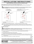
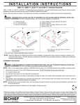
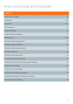
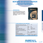
INSTALLATION INSTRUCTIONS SINGLE CIRCUIT KIT The Underfloor Heating Store Ltd Unit 17 Gardiners Lane South Basildon Essex SS14 3AP Tel: 0800 0778374 Fax: 01268 527199 E-mail: [email protected] 1. Installation 1) 2) 3) 4) Read all of this document first! Select a suitable location for the pump/control valve unit and mount on the wall. Fit the two ½”x16mm pipe adaptors as shown in the illustration. Refer to the typical pipe installation drawings and determine the pipe layout- the layout is not critical and can be varied to suit site conditions, the important criteria being the pipe spacing. 5) Pipe spacing is 200mm for a conservatory & 250mm for other rooms. 6) The pipe is marked every metre by the metre. 7) Pipes should be laid 100mm away from walls. 8) Do not lay pipe under kitchen units. 9) Start from the far end of the room and work back to the pump/control valve unit location. 10) To lay the circuit, cut the pipe end squarely using the plastic pipe cutter, re-round the pipe end with the tool provided, place the nut over the pipe, the olive and insert is fully fitted over the end of the pipe and the assembly attached to the pipe adaptor. Tighten the nut (it is not necessary to over tighten) using an open end spanner. 11) Lay the pipe as planned, fixing every 1.0m and return to the manifold. 12) If the pipe is kinked when bending, the pipe should be straightened and rearranged so that the location of the kink remains in a straight length, no other remedial action is required. 13) Prevent people from walking on the pipes, keep tools etc away from the pipes and use running boards. The pipe is very tough, but it is better to be safe than sorry. 14) It is IMPORTANT that the underfloor heating system is properly filled with water (use a garden hose) and purged completely of air to ensure correct operation, . 15) IT IS NOT ADEQUATE TO FILL THE SYSTEM USING THE BOILER FILLING LOOP!! 1a. Commissioning. 1) Screed or chipboard flooring should be laid immediately after pipelaying to protect the pipe. 2) Concrete screed floors must be cured before any heat is applied, a general rule of thumb is to allow 1 day per 2 millimetres of screed. 3) Timber floor with drymix infill can have heat applied immediately, the drymix must be dried completely before laying the flooring. 4) Hardwood timber flooring must be ‘conditioned’ before fixing. 5) It is important to purge the pipework from the boiler to the manifold, to avoid air being introduced into the underfloor heating system. 6) Initially start the system with the thermostatic valve set at min (35c). 7) Increase the setting by 5 per day, up to a maximum of 50 for concrete floors, max 60 for timber floors. 8) NOTE. When first starting up the system it may take 12-24 hours for the heating effect to become apparent! 1b. Electrical 1) Thermostat position in the room is not critical but positions affected by the sun should be avoided, mounting height approx.1.5M. 2) The pump control valve unit incorporates a pipe thermostat and will not operate unless hot water is available from the boiler/heating system. 2. Electrical TYPICAL ELECTRICAL CONNECTION SINGLE CIRCUIT UFH + EXISTING S PLAN SYSTEM +SYSTEM BOILER DS1,DT,PRT,PRT-TS thermostat (underfloor heating) TP5000Si thermostat (underfloor heating) room thermostat (radiators) 2 3 ATC cylinder thermostat Supply to UFH pump. N L A1 NL 123 A2 Supply to UFH pump. HORSTMAN H37 N L 5 1 3 123 12 3 RET230P thermostat (underfloor heating) Supply 230V AC Earth wires omitted for clarity! HP motorised valve DHW HP motorised valve radiators M Supply to UFH pump. HP motorised valve underfloor heating M RET230L thermostat (underfloor heating) M NL 3 Supply to boiler & boiler pump Supply to UFH pump. TYPICAL ELECTRICAL CONNECTION SINGLE CIRCUIT UFH + RADIATORS + COMBINATION BOILER DS1,DT,PRT,PRT-TS thermostat (underfloor heating) TP5000Si thermostat (underfloor heating) room thermostat (radiators) N L 1 2 4 2 3 Supply to UFH pump. DANFOSS FP975-2H 5 N L A1 A2 Supply to UFH pump. 123 RET230P thermostat (underfloor heating) Earth wires omitted for clarity! HP motorised valve radiators M NL Supply 230V AC 123 Supply to UFH pump. HP motorised valve underfloor heating RET230L thermostat (underfloor heating) M NL 3 Volt free to room thermostat connections in combination boiler. WARNING: Exercise care when connecting to boiler connections, its important that a voltage is not applied to boiler terminals from this control system or damage to boiler may occur. Supply to UFH pump. 3. System schematics. Schematic for system boiler & UFH + radiators + hot water HWC Motorised valves Boiler Boiler pump Schematic for gas combination boiler & underfloor heating + radiators Motorised valves Combination boiler UFH 4. Pump/control valve assembly. return to boiler water temperature control flow from boiler ½" ½" xx 16mm 16mm coupling coupling from UFH circuit pump to UFH circuit ½" x 16mm coupling 5. Typical pipe layout.