1
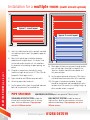
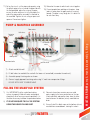
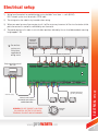
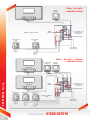
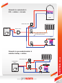
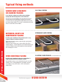
INSTALLATION MANUAL
Water
Underfloor
Heating Kit
For multiple rooms
50 year pipe warranty
CE approved
Easy to install
MULTIPLE ROOM SYSTEM INSTALLATION MANUAL
MULTI ROOM SYSTEM INSTALLATION
AT ION
Manufactured in
Europe!
Thank you for investing in our industry
oor heating system
leading ProWarm™ underfl
underfloor
ProWarm™ Water Underfloor Heating Systems are the ideal choice for homeowners and tradesmen
wishing to install a premium branded water underfloor heating kit.
This instruction manual contains important information regarding the safe installation and operation
of your underfloor heating system. Please read carefully.
See our online videos for helpful guidance
In addition to this manual we have online installation videos that
guide you through each stage of process with easy to follow CGi
graphics and helpful dialogue. Scan QR code to watch video
Technical support
2
01268 567019
Before
Be
ef
you begin Installing:
Pleaas read through these instructions carefully and check that you have
Please
all tthe components required. ProWarm™ water underfloor heating kits
contain
con
nta everything you need in one box for your water underfloor heating
project.
pro
jec NB: This multi zone system is controlled by multiple thermostats.
A rated UPS 2 Grundfos pump
Pipe rerounding tool
P
PE-Xb-multilayer pipe to suit area
Wiring centre
EEdging insulation (NA: for low profile)
All pipe connections to fix pipe to
pump and manifold
M
Manual
anual Thermostat
A
Actuators
ctuators
P
Pipe
pe Staples
We use high quality multi layered pipe (PE-Xb-Al-HDPE)
in all our ProWarm™ water underfloor heating systems
AN INNER LAYER in cross-linked polyethylene
PE-Xb (crosslinked with silanes)
AN INTERMEDIATE LAYER in aluminium
alloy, butt-welded along length of pipe.
PIPE
WARRANTY
PE-Xb-Al-HDPE.
Working pressure &
temperature10bar, 95°C.
100% oxygen impermeable.
TWO BINDING LAYERS of adhesive bind
the metal pipe with the two outer layers in
cross-linked polyethylene
Lifetime warranty.
www.
prowarm.com
AN OUTER LAYER in crosslinked polyethylene PE-Xb
(crosslinked with silanes).
MULTI ROOM SYSTEM INSTALLATION
P
Pipe
pe Cutters
3
Installation for a multiple room (multi circuit system)
Typical 1 circuit layout
Typical 2 circuit layout
1) Select a suitable location for the pump & manifold
unit and mount on the wall. See opposite page for
assembly.
MULTIPLE ROOM pipe layout
2) Refer to the typical pipe installation drawings
and determine the pipe layout - the layout is not
critical and can be varied to suit site conditions,
the important criteria being the pipe spacing, see
below.
4) The pipe is marked every metre by the metre.
(maximum length for any circuit is 110m, 70m for
low profile 12mm pipe circuit).
5) Pipes should be laid 100mm away from walls.
6) Do not lay pipe under fixed units.
7) Lay the rooms furthest from the manifold and work
back, do the room with the manifold last.
PIPE SPACINGS
9) Lay the pipe as planned, fixing every 1.0m if on a
screeded celotex base and return to the manifold.
10) If the pipe is kinked when bending, the pipe
should be straightened and rearranged so that the
location of the kink remains in a straight length, no
other remedial action is required.
LOW PROFILE SYSTEM panels are spaced at 150mm centres
STANDARD OUTPUT SYSTEM suitable for
internal well insulated areas such as a living
room, kitchen or bathroom. Pipe spacings
are set at 250mm centres.
Technical support
4
8) When pipes to/from one area pass through another
area, the two pipes should be run together, the
‘bunches’ of pipes should then be spaced as if
they were one pipe.
HIGH OUTPUT SYSTEM suitable for areas of
high heat loss, ideal for conservatories, extensions
and external buildings. Pipe spacings are set at
200mm centres.
01268 567019
11) To lay the circuit, cut the pipe end squarely using
the plastic pipe cutter, re-round the pipe end with
the tool provided, place the nut over the pipe,
ensure the olive and insert is fully fitted over the
end of the pipe and the assembly is attached to
the manifold. Tighten the nut using an open end
spanner. Do not over tighten.
12) Note also the room to which each circuit applies.
13) Prevent people from walking on the pipes, keep
tools etc away from the pipes and use running
boards. The pipe is very tough, but it is better to
be safe than sorry.
PUMP & MANIFOLD ASSEMBLY
Wiring centre
Flow meters
Ball valves
Pump
Fill & drain
valves
Actuators
Mixing valve
Flow from boiler
to UFH circuit
1) Attach manifold to wall.
2) Fit ball valves to manifold, the end with the loose nut to manifold( remember the washers!).
3) Assemble pump & mixing valve as shown.
4) Connect supply pipework to mixing valve using ¾" male iron compression fittings.
DO NOT APPLY HEAT TO MIXING VALVE
FILLING THE MANIFOLD SYSTEM
1) It is IMPORTANT that the underfloor heating
system is properly filled with water and purged
completely of air to ensure correct operation, it is
therefore necessary to follow the procedure below.
2) IT IS NOT ADEQUATE TO FILL THE SYSTEM
USING THE BOILER FILLING LOOP!
www.
3) Connect a hose from a mains pressure cold
water supply to the hose connection on the top
(flow) manifold, and another hose from the hose
connection on the bottom (return) manifold to a
drain.
4) Ensure that all the black caps on the bottom (return)
manifold are screwed down, closing the valves.
prowarm.com
MULTIPLE ROOM pump & manifold assembly & filling
Return to
boiler
5
FILLING THE MANIFOLD SYSTEM (cont.)
5) Ensure that the main flow & return ball valves are
closed on the manifold.
10) Open the third circuit valve and close the second
etc.
6) Turn on the water and open the hose connection
valve on the top (flow) manifold.
11) Continue until the last circuit has been purged and
close the hose connection valve on the bottom
(return) manifold before closing the last circuit
valve (black cap).
MULTIPLE ROOM filling the manifold / commisioning / mantenance
7) Open the first circuit valve by unscrewing the
black cap allowing water to flow into the pipe.
8) Open the hose connection valve on the bottom
(return manifold) allowing water to flow freely
into the drain until the water is clear with no air
bubbles.
13) Close hose connection valve on the top (flow
manifold) and remove the hoses.
9) Open the second circuit valve (black cap) and
close the first.
COMMISIONING
1) Screed or chipboard flooring should be laid
immediately after pipelaying to protect the pipe.
2) Concrete screed floors must be cured before any
heat is applied, a general rule of thumb is to allow
1 day per 2 millimetres of screed.
3) Timber floor with drymix infill can have heat
applied immediately, the drymix must be dried
completely before laying the flooring.
should be set at a figure calculated by dividing
the length of pipe for that zone by 40. Example:
Circuit 1, 85m÷40 = approx 2 on the scale. Low
profile systems circuit at 70m÷40=1.75.
8) Fit actuators to valves after connecting the control
wiring.
9) It is important that the actuators are screwed
tightly on to the valve.
4) Hardwood timber flooring must be ‘conditioned’
before fixing.
7) Initially start the system with the thermostatic
valve set at min (35°c).
5) It is important to purge the pipework from
the boiler to the manifold, to avoid air being
introduced into the underfloor heating system.
8
6) It is not normally necessary to balance the
system but if required follow this procedure. The
system is balanced by running the pump, and
adjusting the flow to each zone by turning the
square spigots under the blue caps on the bottom
manifold, the flow in the respective sight glasses
9) The flow & return from the boiler should be
connected to the manifold connections shown
using compression couplings.
MAINTENANCE
Increase the setting by 5° per day, up to a
maximum of 50° for concrete floors, max 65° for
timber floors.
10) NOTE. When first starting up the system it may
take 12-24 hours for the heating effect to become
apparent!
It is recommended that the following maintenance be carried out annually.
1) Check that all actuator nuts are tightened firmly and that actuators are not loose. 2) Remove end plug from
pump and check that pump rotates when energised. 3) Turn up thermostats and check that actuators move into
open position also check flow gauges are indicating. If not, re-pressurise manifold, remove indicator, clean and
replace, repressurise manifold.
Technical support
6
12) While under pressure, check manifold & pipework
for leakage.
01268 567019
Electrical setup
1) Wiring from thermostats to manifold wiring centre should be 1mm 3core + earth (6243Y).
NB: A network system must be wired in 'CAT6' cable.
2) The wiring centre has a back entry to avoid surface wiring.
3) Where one room has more than one pipe circuit it will be necessary to connect all the circuit actuators to that
particular zone on the controller, controlled by one thermostat.
4) Thermostat position in the room is not critical but positions affected by the sun should be avoided, mounting
height approx 1.5M
Heatmiser
DS1/DT/
PRT/PRT-TS
For wireless
systems see
instructions
supplied with
wiring centre
N L
1 2 3
N L
A1 A2
N L
N L 1 2 3
3
2 3
room thermostat connections
Only required for manual
dial stats
TIME CLOCK
ZONE 1
ZONE 2
ZONE 3
ZONE 4
ZONE 5
ZONE 6
ZONE 7
ZONE 8
EXTERNAL
PROGRAMMER
L N
GrOr L E N
L L N N
L L N N
L L N N L L N N
ZONE 1
ZONE 2
ZONE 3
ZONE 4
L L N N
ZONE 5
L L N N L L N N
ZONE 6
ZONE 7
L L N N
ZONE 8
manifold actuators
(up to 4 per zone)
230v AC supply
connect across room
thermostat connections in
combination boiler
WARNING: DO NOT CONNECT 230V FROM
THIS CONTROL SYSTEM TO THE BOILER
TERMINALS OR BOILER MAY BE DAMAGED!
www.
prowarm.com
manifold
pump
ELECTRICAL setuup
L E N IN OUT L E N
MAINS BOILER UFH P/P UFH VALVE
7
cylinder
thermostat
Boiler + hot water
+ underfloor heating
hot water programmer
N
L
refer to wiring centre
schematic for these
connections
Supply
230V AC
Earth wires omitted for clarity!
X ufh manifold 1
motorised valve
DHW
motorised valve
UFH1
M
M
power to boiler
& boiler pump
room thermostat
(radiators)
Boiler + hot water + radiators
+ underfloor heating
cylinder
thermostat
hot water + radiators
programmer
ELECTRICAL setuup
N
L
underfloor heating
programmer
N
Supply
230V AC
L
X ufh manifold 1
motorised valve
DHW
M
motorised valve
radiators
M
motorised valve
UFH1
M
Earth wires omitted for
clarity!
power to boiler
& boiler pump
Technical support
8
refer to wiring centre
schematic for these
connections
01268 567019
Schematic for system boiler &
UFH + radiators + hot water
HWC
Motorised valves
Boiler pump
(not needed on a UHF only
/ Hot water sytsem)
UFH
Schematic for gas combination boiler &
underfloor heating + radiators
Motorised valves
Combination
Boiler
www.
UFH
prowarm.com
ELECTRICAL setuup
Boiler
9
Typical fixing methods
UNDER NEW CONCRETE
OR SCREED FLOORS
CLIP RAIL SYSTEM
A cost effective solution for installing water underfloor
heating into new build properties or new extensions.
This type of system installation is the most popular and cost
effective type on the market today, the pipes are incased in
screed or concrete meaning that the whole floor warms up like
one huge storage radiator. This system is normally for new build
houses or extensions/conservatories.
BETWEEN JOISTS OR
SUSPENDED FLOORS
SPREADER PLATE SYSTEM
Installing water underfloor heating between joists is easy
using our different installation solutions.
TYPICAL FIXING METHODS
Please note all in joist systems require the pipe spacing to be
200mm apart or less
This means you need to select a conservatory style kit or a
multiple room kit – standard room kits are designed with the pipe
spacing at 250mm centers which would mean you would not
have enough pipe in the kit
OVER EXISTING FLOORS
Installing water underfloor heating over existing floors is
simple using our different installation solutions.
Our overfloor systems can be installed directly over any solid
subfloor such as existing floorboards, plywood or concrete/
screed floors, or any solid surface such as existing tiles/
wooden floors.
Technical support
10
FLOATING FLOOR PANELS for finished timber floor
01268 567019
CLIPPED DIRECT WITH STAPLES
DRY BISCUIT MIX/ SCREED SYSTEM
IN JOIST FOIL BOARDS
SOLID FLOOR PANELS for finished tiled floor
For more information on various floor
fixings watch our helpful videos for step
by step guidance.
Scan QR code
to watch videos
www.
prowarm.com
TYPICAL FIXING METHODS
PLASTIC EGG CRATE SYSTEM
11
Visit us online for a list of suppliers:
www.prowarm.com
Call us direct for technical advice:
01268 567019
Unit 12, Carnival Park, Carnival Way, Basildon, Essex, SS14 3WN
T: 01268 567019
www.
.com