1
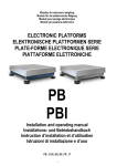
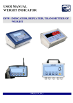
Modules for electronic weighing
ELECTRONIC PLATFORMS
PB
PBI
Installation and operating manual
PB_13.02_EN_DE_FR _IT
1
ENGLISH
INDEX
IMPORTANT WARNINGS ..........................................................................................................................4
1. INTRODUCTION.....................................................................................................................................5
1.1 TECHNICAL SPECIFICATIONS .......................................................................................................5
2. INSTALLATION ......................................................................................................................................6
2.1 INSTALLING THE CSP COLUMN ....................................................................................................6
2.2 ASSEMBLING PBI+PBICL…+PBICLST+DFWLI ..............................................................................8
2.3 ASSEMBLING PB+PBCL…+PBCLST+DFWLI (WALL-E) ...............................................................9
3. MAINTENANCE AND REPAIRS ..........................................................................................................10
4. TRANSPORTING THE PLATFORM .....................................................................................................10
5. DRAWING.............................................................................................................................................11
5.1 DIMENSIONS .................................................................................................................................11
5.2 TABLE OF PB SERIES PLATFORM ..............................................................................................11
5.3 INSTALLATION ..............................................................................................................................12
6. PLATFORM SHIELDED CABLE AND CONNECTOR..........................................................................13
WARRANTY AND AUTHORIZED SERVICE CENTRE ............................................................................14
3
IMPORTANT WARNINGS
Put the platform in a place in which the following conditions are respected:
-Flat, level, stable support surface
- Stable and absent of vibrations,
-Absence of dust or aggressive vapours,
- Absence of air currents,
- Moderate temperature and humidity (not exposed to direct sunlight or near heat sources).
Make sure to level the platform by adjusting the feel (see INSTALLATION instructions).
Do not weld, perforate or modify the structure without consulting the reseller. If it is damaged or
tampered with the warranty conditions will be annulled.
If the place of use is a humid or wet environment, the installation must be carried out in such a way so
that water stagnation and/or scraps under the structure are avoided.
The platform must be connected to a weigh indicator. Refer to weigh indicator owner’s manual for
connection instruction (Make sure that the connections are correct).
Do not step, crush or expose to sunlight the connecting screen cable.
YOU NEED TO GROUND the metallic structure of the platform, especially if you need to weigh
materials that, while handled, can cause electrical discharges (dust, plastic materials, etc.). If there
are any doubts, consult the reseller.
DO NOT INSTALL IN HAZARDOUS ENVIRONMENTS.
(unless specifically made for this use)
Do not use solvents when cleaning.
4
1. INTRODUCTION
All PB series weighing modules are built with high quality materials and are calibrated in such a way,
which guarantees full reliability and weighing accuracy that lasts in time. The measuring elements are
load cells, produced in conformance to the OIML R60 standards.
The PB platforms have load cells connected to the indicator with a shielded cable, 3 meters of length.
Every PB series weighing module is built and engineered to guarantee a uniform detection of the load
on the load cell weighing modules, even in adverse environment conditions.
The electronic weighing platform PB series, are suitable for creating weighing systems or small and
medium, capacity, piece counter. The weigh capacity goes from 6 kg to 600 kg.
1.1 TECHNICAL SPECIFICATIONS
- Blue, oven-fired painted steel tubular structure.
- Stainless steel load surface.
- Equipped with one, OFF-CENTER, aluminium load cell with dust and humidity protection IP65.
- Shielded cable, 3 meters of length.
SPECIFICATION
Load cell
Power supply
Nominal output (max. load)
Input resistance
Combined error
Operating temperature range
off-center, direct load
15 Vdc Max
2 mV/V
350ohm
0,02 % R.O.
-10 / + 40 °C
ACCESSORIES
Floor-mounted indicator column.
5
2. INSTALLATION
NOTE: The weighing module must be connected to its appropriate weight indicator with the
cable coming from the load cell. The indicator, connected to the platform, can not be calibrated
if not powered.
It is the customer’s responsibility to prepare and calibrate the indicator.
For any further detail, refer to the technical and operational manual, supplied with the indicator.
A) Unpack then product.
B) Remove the locking catch for the transportation (see section 5.3).
C) Level the platform by adjusting the adjustable feet. The stability of the platform is very important.
ALL THE CORNERS MUST REST IN A UNIFORM WAY. Carefully check that all feet fully rest on the
ground and that the platform, loaded on the corner, is not unstable (if a corner is not resting on the
ground its relative foot is easier to turn).
D) Connect the shielded cable from the load cell to the weigh indicator (refer to the indicator manual).
The cable must be free, so that the resistances are not energised, which could alter the measurement.
E) You need to ground the metallic structure of the platform, especially if you need to weigh materials
that, while handled, can cause electrical discharges (dust, plastic materials, etc.). If there are any
doubts, consult the reseller.
F) Perform the indicator calibration and setup as shown by the manual
G) MAKE SURE TO FOLLOW THE WARNINGS AT PAGE 4.
2.1 INSTALLING THE CSP38I COLUMN (FIG.1)
1.
2.
3.
4.
5.
6.
7.
8.
9.
Lock column (2) to base (7) with the two fitted screws (10 and 3).
Screw nut on feet (8).
Screw the four feet (8) to the base (7).
Make the connecting cable, coming from the scale, run inside column (2) until you get it out from
hole.
Connect the cable to the terminal board referring to the indicator technical-user manual.
Lock column (2) to the support for the indicator (9 and 5) with the two fitted screws (11 and 5).
Set the weigh indicator (6) to the support (9) with screws (4). Make sure the cable, connecting the
scale, is stretched.
Set the column CSP perpendicular to the floor, by adjusting feet (8).
Thigh nut on feet (8).
6
FIG.1
7
2.2 ASSEMBLING PBI+PBICL…+PBICLST+DFWLI (FIG.2)
Components:
1. Bench Scale
2. Support
3. n.4 VTC M6X16 inox (screw)
4. n.1 column PBICL350/ PBICL500/ PBICL700
5. n.2 VTC M3x5 inox (screw)
6. n.1 13PBICLST indicator bracket
7. n.2 M6 exagonal nuts
8. DFWLI indicator
Please note that the M6 hex nuts (part 7) are supplied with the DFWLI. Remove the DFWLI wall
brackets and use nuts for connection to 13PBICLST.
Fig.2
8
2.3 ASSEMBLING PB+PBCL…+PBCLST+DFWLI (WALL-E) (FIG.3)
Fig.3
n.
1
2
3
4
5
6
7
8
9
10
q.ty
1
1
1
1
2
1
4
2
2
2
description
DFWL Indicatore
Stainless steel column
DFWL holder
Foot
M6x1 hexagonal nut
Platform
M6x12 screws
6.4x18 washer
M4x6 screw
M6x12 screw
9
3. MAINTENANCE AND REPAIRS
TO OBTAIN THE BEST PERFORMANCE
-
One should keep the platform clean. If dirt and dust accumulate on the platform one should clean it
with a damp cloth or with the common cleaning products (do not use SOLVENTS and ACIDS)
- Avoid platform collisions because this could cause serious damages.
BREAKDOWNS AND OVERLOADS
If you think the platform is broken or damaged disconnect it in a permanent way. Do this if the platform:
- appears to be damaged.
- does not work.
- has been loaded more than its tolerable limits (which could happen during the transportation or at
time of storage).
4. TRANSPORTING THE PLATFORM
To pack the platform follow the procedure below:
a) turn off the instrument.
b) disconnect the platform’s instrument.
c) Reposition the locking catch for the transportation.
d) Pack it like when it was received.
10
5. DRAWINGS
5.1 DIMENSIONS
FIG.2
5.2 TABLE OF PB SERIES PLATFORM
PLATFORM
MODEL
PBT
PBQ
PBX
PBE
MAX LOAD
kg
6 / 15 / 30
30 / 60 / 150
60 / 150 / 300
300 / 600
A
300
400
600
800
N.B. All dimensions can be changed without notice.
11
DIMENSION mm
B
300
400
600
800
C
130
140
150
165
5.3 INSTALLATION
To protect the platform during the transport, 4 plastic gaskets are installed above the limiting bolt.
Before using the scale, remove the 4 plastic gaskets.
12
6. PLATFORM SHIELDED CABLE AND CONNECTOR
PBT-PBQ-PBX
4-WIRE LOAD CELL
CABLE
CONNECTOR 5-PIN
(SCALEHOUSE INDICATOR)
Red
5
Black
4
Green
1
White
2
Transparent
CONNECTOR 7-PIN
(DINI ARGEO INDICATOR)
1, 4
2, 3
6
5
MEANING
6-WIRE LOAD CELL
CABLE
CONNECTOR 5-PIN
(SCALEHOUSE INDICATOR)
Red
5
Black
4
Green
1
White
2
Blu
5
Brown/Yellow
4
Transparent
CONNECTOR 7-PIN
(DINI ARGEO INDICATOR)
1
2
6
5
4
3
MEANING
4-WIRE LOAD CELL
CABLE
CONNECTOR 5-PIN
(SCALEHOUSE INDICATOR)
Red
5
Yellow
4
Blue
1
White
2
Transparent
CONNECTOR 7-PIN
(DINI ARGEO INDICATOR)
1, 4
2, 3
6
5
MEANING
6-WIRE LOAD CELL
CABLE
CONNECTOR 5-PIN
(SCALEHOUSE INDICATOR)
Red
5
Yellow
4
Blue
1
White
2
Brown
5
Black
4
Transparent
CONNECTOR 7-PIN
(DINI ARGEO INDICATOR)
1
2
6
5
4
3
MEANING
EXCITATION +
EXCITATION SIGNAL +
SIGNAL EARTH BRAIDING
EXCITATION +
EXCITATION SIGNAL +
SIGNAL –
SENSE +
SENSE EARTH BRAIDING
PBE
13
EXCITATION +
EXCITATION SIGNAL +
SIGNAL EARTH BRAIDING
EXCITATION +
EXCITATION SIGNAL +
SIGNAL –
SENSE +
SENSE EARTH BRAIDING
WARRANTY
Scale House products are guaranteed for a period of twelve months
from delivery, excluding the parts classified as expendable materials
such as mechanical printing heads, batteries, electric motors and
wheels. The warranty for these expendable materials is three months.
The warranty refers to breakdowns resulting from any construction
defect or material defect of the product supplied and covers the cost
of labor and spare parts. The product must be returned to the Seller
address in its original packaging with shipping paid by the sender.
The warranty does not apply to breakdowns due to improper use or
non-observance of the operating instructions, electrical phenomenon,
unauthorized repair attempt, connection to other equipment or
removal of any product identification elements (serial number, label,
etc.). This warranty does not provide for any compensation for
damages, direct or indirect, incurred by the user due to complete or
partial failure of instruments, even during the warranty period. The
warranty for the load cells excludes the damages caused by knocks
and overloads.
AUTHORIZED SERVICE CENTER STAMP
14