1
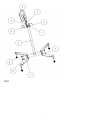
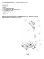
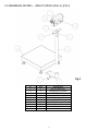
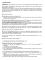
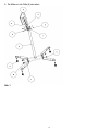
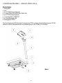
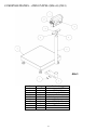
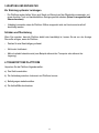
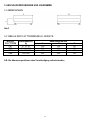
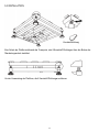
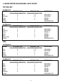
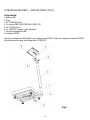
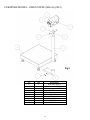
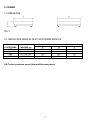
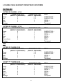
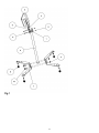
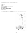
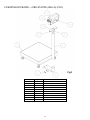
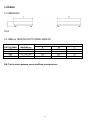
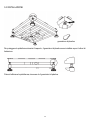
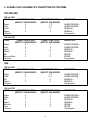
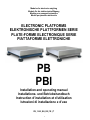
Modules for electronic weighing
Module für die elektronische Wägung
Module pour pesage électronique
Moduli per pesatura elettronica
ELECTRONIC PLATFORMS
ELEKTRONISCHE PLATTFORMEN SERIE
PLATE-FORME ELECTRONIQUE SERIE
PIATTAFORME ELETTRONICHE
PB
PBI
Installation and operating manual
Installations- und Betriebshandbuch
Instruction d’installation et d’utilisation
Istruzioni di installazione e d’uso
PB_13.02_EN_DE_FR _IT
1
LANGUAGES
SPRACHEN
LANGUES
LINGUE
ENGLISH ..........................................................................................................3
DEUTSCH .......................................................................................................15
FRANÇAIS ......................................................................................................27
ITALIANO .......................................................................................................39
2
ENGLISH
INDEX
IMPORTANT WARNINGS ..........................................................................................................................4
1. INTRODUCTION.....................................................................................................................................5
1.1 TECHNICAL SPECIFICATIONS .......................................................................................................5
2. INSTALLATION ......................................................................................................................................6
2.1 INSTALLING THE CSP COLUMN ....................................................................................................6
2.2 ASSEMBLING PBI+PBICL…+PBICLST+DFWLI ..............................................................................8
2.3 ASSEMBLING PB+PBCL…+PBCLST+DFWLI (WALL-E) ...............................................................9
3. MAINTENANCE AND REPAIRS ..........................................................................................................10
4. TRANSPORTING THE PLATFORM .....................................................................................................10
5. DRAWING.............................................................................................................................................11
5.1 DIMENSIONS .................................................................................................................................11
5.2 TABLE OF PB SERIES PLATFORM ..............................................................................................11
5.3 INSTALLATION ..............................................................................................................................12
6. PLATFORM SHIELDED CABLE AND CONNECTOR..........................................................................13
WARRANTY AND AUTHORIZED SERVICE CENTRE ............................................................................14
3
IMPORTANT WARNINGS
Put the platform in a place in which the following conditions are respected:
-Flat, level, stable support surface
- Stable and absent of vibrations,
-Absence of dust or aggressive vapours,
- Absence of air currents,
- Moderate temperature and humidity (not exposed to direct sunlight or near heat sources).
Make sure to level the platform by adjusting the feel (see INSTALLATION instructions).
Do not weld, perforate or modify the structure without consulting the reseller. If it is damaged or
tampered with the warranty conditions will be annulled.
If the place of use is a humid or wet environment, the installation must be carried out in such a way so
that water stagnation and/or scraps under the structure are avoided.
The platform must be connected to a weigh indicator. Refer to weigh indicator owner’s manual for
connection instruction (Make sure that the connections are correct).
Do not step, crush or expose to sunlight the connecting screen cable.
YOU NEED TO GROUND the metallic structure of the platform, especially if you need to weigh
materials that, while handled, can cause electrical discharges (dust, plastic materials, etc.). If there
are any doubts, consult the reseller.
DO NOT INSTALL IN HAZARDOUS ENVIRONMENTS.
(unless specifically made for this use)
Do not use solvents when cleaning.
4
1. INTRODUCTION
All PB series weighing modules are built with high quality materials and are calibrated in such a way,
which guarantees full reliability and weighing accuracy that lasts in time. The measuring elements are
load cells, produced in conformance to the OIML R60 standards.
The PB platforms have load cells connected to the indicator with a shielded cable, 3 meters of length.
Every PB series weighing module is built and engineered to guarantee a uniform detection of the load
on the load cell weighing modules, even in adverse environment conditions.
The electronic weighing platform PB series, are suitable for creating weighing systems or small and
medium, capacity, piece counter. The weigh capacity goes from 6 kg to 600 kg.
1.1 TECHNICAL SPECIFICATIONS
- Blue, oven-fired painted steel tubular structure.
- Stainless steel load surface.
- Equipped with one, OFF-CENTER, aluminium load cell with dust and humidity protection IP65.
- Shielded cable, 3 meters of length.
SPECIFICATION
Load cell
Power supply
Nominal output (max. load)
Input resistance
Combined error
Operating temperature range
off-center, direct load
15 Vdc Max
2 mV/V
350ohm
0,02 % R.O.
-10 / + 40 °C
ACCESSORIES
Floor-mounted indicator column.
5
2. INSTALLATION
NOTE: The weighing module must be connected to its appropriate weight indicator with the
cable coming from the load cell. The indicator, connected to the platform, can not be calibrated
if not powered.
It is the customer’s responsibility to prepare and calibrate the indicator.
For any further detail, refer to the technical and operational manual, supplied with the indicator.
A) Unpack then product.
B) Remove the locking catch for the transportation (see section 5.3).
C) Level the platform by adjusting the adjustable feet. The stability of the platform is very important.
ALL THE CORNERS MUST REST IN A UNIFORM WAY. Carefully check that all feet fully rest on the
ground and that the platform, loaded on the corner, is not unstable (if a corner is not resting on the
ground its relative foot is easier to turn).
D) Connect the shielded cable from the load cell to the weigh indicator (refer to the indicator manual).
The cable must be free, so that the resistances are not energised, which could alter the measurement.
E) You need to ground the metallic structure of the platform, especially if you need to weigh materials
that, while handled, can cause electrical discharges (dust, plastic materials, etc.). If there are any
doubts, consult the reseller.
F) Perform the indicator calibration and setup as shown by the manual
G) MAKE SURE TO FOLLOW THE WARNINGS AT PAGE 4.
2.1 INSTALLING THE CSP38I COLUMN (FIG.1)
1.
2.
3.
4.
5.
6.
7.
8.
9.
Lock column (2) to base (7) with the two fitted screws (10 and 3).
Screw nut on feet (8).
Screw the four feet (8) to the base (7).
Make the connecting cable, coming from the scale, run inside column (2) until you get it out from
hole.
Connect the cable to the terminal board referring to the indicator technical-user manual.
Lock column (2) to the support for the indicator (9 and 5) with the two fitted screws (11 and 5).
Set the weigh indicator (6) to the support (9) with screws (4). Make sure the cable, connecting the
scale, is stretched.
Set the column CSP perpendicular to the floor, by adjusting feet (8).
Thigh nut on feet (8).
6
FIG.1
7
2.2 ASSEMBLING PBI+PBICL…+PBICLST+DFWLI (FIG.2)
Components:
1. Bench Scale
2. Support
3. n.4 VTC M6X16 inox (screw)
4. n.1 column PBICL350/ PBICL500/ PBICL700
5. n.2 VTC M3x5 inox (screw)
6. n.1 13PBICLST indicator bracket
7. n.2 M6 exagonal nuts
8. DFWLI indicator
Please note that the M6 hex nuts (part 7) are supplied with the DFWLI. Remove the DFWLI wall
brackets and use nuts for connection to 13PBICLST.
Fig.2
8
2.3 ASSEMBLING PB+PBCL…+PBCLST+DFWLI (WALL-E) (FIG.3)
Fig.3
n.
1
2
3
4
5
6
7
8
9
10
q.ty
1
1
1
1
2
1
4
2
2
2
description
DFWL Indicatore
Stainless steel column
DFWL holder
Foot
M6x1 hexagonal nut
Platform
M6x12 screws
6.4x18 washer
M4x6 screw
M6x12 screw
9
3. MAINTENANCE AND REPAIRS
TO OBTAIN THE BEST PERFORMANCE
-
One should keep the platform clean. If dirt and dust accumulate on the platform one should clean it
with a damp cloth or with the common cleaning products (do not use SOLVENTS and ACIDS)
- Avoid platform collisions because this could cause serious damages.
BREAKDOWNS AND OVERLOADS
If you think the platform is broken or damaged disconnect it in a permanent way. Do this if the platform:
- appears to be damaged.
- does not work.
- has been loaded more than its tolerable limits (which could happen during the transportation or at
time of storage).
4. TRANSPORTING THE PLATFORM
To pack the platform follow the procedure below:
a) turn off the instrument.
b) disconnect the platform’s instrument.
c) Reposition the locking catch for the transportation.
d) Pack it like when it was received.
10
5. DRAWINGS
5.1 DIMENSIONS
FIG.2
5.2 TABLE OF PB SERIES PLATFORM
PLATFORM
MODEL
PBT
PBQ
PBX
PBE
MAX LOAD
kg
6 / 15 / 30
30 / 60 / 150
60 / 150 / 300
300 / 600
A
300
400
600
800
N.B. All dimensions can be changed without notice.
11
DIMENSION mm
B
300
400
600
800
C
130
140
150
165
5.3 INSTALLATION
To protect the platform during the transport, 4 plastic gaskets are installed above the limiting bolt.
Before using the scale, remove the 4 plastic gaskets.
12
6. PLATFORM SHIELDED CABLE AND CONNECTOR
PBT-PBQ-PBX
4-WIRE LOAD CELL
CABLE
CONNECTOR 5-PIN
(SCALEHOUSE INDICATOR)
Red
5
Black
4
Green
1
White
2
Transparent
CONNECTOR 7-PIN
(DINI ARGEO INDICATOR)
1, 4
2, 3
6
5
MEANING
6-WIRE LOAD CELL
CABLE
CONNECTOR 5-PIN
(SCALEHOUSE INDICATOR)
Red
5
Black
4
Green
1
White
2
Blu
5
Brown/Yellow
4
Transparent
CONNECTOR 7-PIN
(DINI ARGEO INDICATOR)
1
2
6
5
4
3
MEANING
4-WIRE LOAD CELL
CABLE
CONNECTOR 5-PIN
(SCALEHOUSE INDICATOR)
Red
5
Yellow
4
Blue
1
White
2
Transparent
CONNECTOR 7-PIN
(DINI ARGEO INDICATOR)
1, 4
2, 3
6
5
MEANING
6-WIRE LOAD CELL
CABLE
CONNECTOR 5-PIN
(SCALEHOUSE INDICATOR)
Red
5
Yellow
4
Blue
1
White
2
Brown
5
Black
4
Transparent
CONNECTOR 7-PIN
(DINI ARGEO INDICATOR)
1
2
6
5
4
3
MEANING
EXCITATION +
EXCITATION SIGNAL +
SIGNAL EARTH BRAIDING
EXCITATION +
EXCITATION SIGNAL +
SIGNAL –
SENSE +
SENSE EARTH BRAIDING
PBE
13
EXCITATION +
EXCITATION SIGNAL +
SIGNAL EARTH BRAIDING
EXCITATION +
EXCITATION SIGNAL +
SIGNAL –
SENSE +
SENSE EARTH BRAIDING
WARRANTY
Scale House products are guaranteed for a period of twelve months
from delivery, excluding the parts classified as expendable materials
such as mechanical printing heads, batteries, electric motors and
wheels. The warranty for these expendable materials is three months.
The warranty refers to breakdowns resulting from any construction
defect or material defect of the product supplied and covers the cost
of labor and spare parts. The product must be returned to the Seller
address in its original packaging with shipping paid by the sender.
The warranty does not apply to breakdowns due to improper use or
non-observance of the operating instructions, electrical phenomenon,
unauthorized repair attempt, connection to other equipment or
removal of any product identification elements (serial number, label,
etc.). This warranty does not provide for any compensation for
damages, direct or indirect, incurred by the user due to complete or
partial failure of instruments, even during the warranty period. The
warranty for the load cells excludes the damages caused by knocks
and overloads.
AUTHORIZED SERVICE CENTER STAMP
14
DEUTSCH
INHALT
WICHTIGE HINWEISE..............................................................................................................................16
1. EINLEITUNG ........................................................................................................................................17
1.1 TECHNISCHE DATEN ...................................................................................................................17
2. INSTALLATION ....................................................................................................................................18
2.1 ANWEISUNGEN FÜR DIE STATIVMONTAGE CSP ......................................................................18
2.2 MONTAGE PBI+PBICL…+PBICLST+DFWLI .................................................................................20
2.3 MONTAGE PB+PBCL…+PBCLST+DFWLI (WALL-E)....................................................................21
3. WARTUNG UND REPARATUR ...........................................................................................................22
4. TRANSPORT DER PLATTFORM ........................................................................................................22
5. ANSCHLUSSZEICHNUNGEN UND -DIAGRAMME .............................................................................23
5.1 ABMESSUNGEN ............................................................................................................................23
5.2 TABELLE DER PLATTFORMMODELLE: SERIE PB ......................................................................23
5.3 INSTALLATION ..............................................................................................................................24
6. ABGESCHIMTES WAAGENKABEL UND STECKER .........................................................................25
GARANTIE UND STEMPEL DER KUNDENDIENSTSTELLE ..................................................................26
15
WICHTIGE HINWEISE
Stellen Sie die Plattform in einer Umgebung auf, wo die folgenden Bedingungen beachtet
werden:
- Gerade und ebene Aufstellfläche,
- Stabilität und keine Vibration,
- Staubfrei und ohne aggressive Dämpfe,
- Ohne Luftströmungen,
- Gemäßigte Temperatur und Feuchtigkeit (vor direkter Sonnenbestrahlung schützen und von
Wärmequellen fernhalten).
Sicherstellen, dass die Plattform unter Nutzung der höheneinstellbaren Füße und der Libelle eben
ausgerichtet ist (siehe Punkt 2).
Die Struktur nicht ohne Zustimmung des Konstrukteurs schweißen, durchbohren oder verändern.
Eventuelle Schäden oder unsachgemäßer Gebrauch löschen jeden Garantieanspruch.
Falls der Gebrauchsort feucht oder nass ist, muß bei der Installation darauf geachtet werden, dass
keine Wasseransammlungen oder –rückstaus und/oder Bohrklein unter der Struktur sind.
Die Plattform muss über das von der Wägezelle kommende Kabel an eine Gewichtsanzeige
angeschlossen werden. Befolgen Sie dafür bitte die Anweisungen für die Anzeige.
Das Verbindungs-Abschirmkabel nicht quetschen oder darauf treten oder Wärmequellen aussetzen.
Erden Sie alle metallischen Teile der Plattform und entfernen Sie den Schutzfilm von der Lastfläche.
Dies ist besonders wichtig, wenn Material gewogen wird, das elektrostatische Entladungen bewirken
kann (Staub, Materialien aus Plastik, etc.).
Fragen Sie im Zweifelsfall den Verkäufer.
NICHT IN BEREICHEN MIT EXPLOSIONSGEFAHR INSTALLIEREN.
(Es sei denn, sie ist extra dafür vorgesehen)
Keine Lösungsmittel für die Reinigung benutzen.
16
1. EINLEITUNG
Alle Wagenmodule der Serie PB sind aus qualitativ hochwertigen Materialien hergestellt so dass eine
langlebige Zuverlässigkeit und Wägegenauigkeit garantiert ist. Die Messelemente bestehen aus 1
Wägezelle hergestellt gemäß der OIML R60 Standards.
Die PB Plattformen haben 1 Wägezelle mit einem abgeschirmten Kabel mit 3 m Länge für den
Anschluss an das Gewichtsanzeigegerät.
Jedes PB Wagenmodul ist gebaut und ausgelgt um eine gleichmäßige Erfassung der auf den
Wägezellenmodulen aufliegenden Last auch unter widrigen Umständen zu garantieren.
Die elektronischen Plattformen PB sind für dem Einsatz der unterschiedlichsten industriellen
Anwendungen ausgelegt, mit Wägebereichen von 6 kg bis 600 kg.
1.1 TECHNISCHE DATEN
– Röhrenförmige Struktur und einbrennlackierter Profilstahl sowie einstellbare Stützfüße.
– Satinierte Inox-Lastplatte AISI 304.
– Die Messelemente sind aus einer eichfähigen “Single Point”-Aluminium Wägezelle, staub- und
feuchtigkeitsgeschützt Schutzart IP65.
– 3m Kabel.
TECHNISCHE DATEN
Wägezelle
Max. Spannung der Versorgung
Nennausgang:
Linearitätsfehler:
Arbeitstemperaturbereich:
Off Center bei direkter Belastung
Max 15 VDC
2 mV/V
0,02% des Nennbereichs der Zelle
-10...+ 40 °C
ZUBEHÖR:
Stativ für Anzeigegeräte.
17
2. INSTALLATION
ANMERKUNG: Das Wägemodul muss über ein von der Anschlussbox kommendes Kabel an eine
dafür geeignete Gewichtsanzeige angeschlossen werden. Befolgen Sie für die Installation bitte die
Anweisungen für die Anzeige.
Die elektronischen Instrumente, die an die Plattformen angeschlossen werden, können nicht kalibriert
werden, bevor sie mit Strom versorgt werden. Der Kunde ist für die Vorbereitungen und Kalibrierung
des Instruments verantwortlich. Beziehen Sie sich für detaillierte Informationen auf das technische
handbuch der Anzeige.
A) Die Verpackung öffnen.
B) Befestigungen entfernen (siehe Abschnitt 5.3).
Bewahren Sie die hölzernen Befestigungen auf und verwenden Sie wieder, falls die Plattform
erneut transportiert werden muss
C) Nivellieren Sie die Plattform durch Einwirken auf die Fuß-Schrauben bis die Nivellierblase sich im
Zentrum der Libelle befindet. Die Stabilität der Plattform ist sehr wichtig.
Alle Ecken MÜSSEN GLEICHMÄSSIG STEHEN. Überprüfen Sie gründlich, dass alle Füße auf dem
Boden feststehen, und dass die Plattform bei Ecklast nicht instabil ist (wenn eine Ecke nicht richtig auf
dem Boden steht, ist der entsprechende Fuß leicht zu bewegen).
D) Verbinden Sie das abgeschirmte Kabel der Wägezelle mit dem Gewichtsanzeigegerät (siehe
Handbuch des Anzeigegerätes). Das Kabel muss frei sein, so dass die Widerstände nicht unter
Spannung stehen, dies könnte die Messung verändern.
E) Erden Sie die Metallteile der Plattform, vor allem wenn Materialien verwogen werden, bei deren
Verarbeitung elektrische Entladungen entstehen können (Staub, plastisches Material, etc.). Bei
Zweifeln halten Sie Rücksprache mit dem Händler.
F) Setup und Kalibrierung der Anzeigegeräte ausführen (siehe Bedienungsanleitung von der
Anzeigegeräte).
G) Befolgen Sie die Warnhinweise auf Seite 14
2.1 ANWEISUNGEN FÜR DIE STATIVMONTAGE CSP
Beachten Sie Zeichnung 1 auf der nächsten Seite.
1. Das Stativ (2) mit den zwei mitgelieferten Schrauben (10 und 3) auf dem Untergestell (7)
befestigen.
2. Die Muttern in die Füße (8) schrauben.
3. Die 4 Füße (8) in das Untergestell(7) schrauben.
4. Das von der Waage kommende Anschlusskabel durch das ganze Stativ (2) ziehen, bis es aus der
Öffnung herauskommt.
5. Die Verbindung durchführen unter Beachtung des Benutzerhandbuchs der Gewichtsanzeige.
6. Das Stativ (2) mit den 2 mitgelieferten Schrauben (11 und 5) an die Anzeigenhalterung (9 und 5)
fixieren.
7. Befestigen Sie die Gewichtsanzeige (6) an die Halterung (9) mit zwei Schrauben (4) und halten Sie
währenddessen das Anschlusskabel der Waage immer gespannt.
8. Positionieren Sie das Stativ CSP lotrecht zum Boden, indem Sie die Füße (8) einstellen.
18
9. Die Muttern in die Füße (8) schrauben.
Abb. 1
19
2.2 MONTAGE PBI+PBICL…+PBICLST+DFWLI (FIG.2)
Bestandteile:
1. Waage PBI
2. Fuß
3. 4x VTC M6X16 aus Edelstahl
4. 1x Stativ PBICL350/ PBICL500/ PBICL700
5. 2x VTC M3x5 aus Edelstahl
6. 1x Anzeigestativ 13PBICLST
7. 2x Sechskantmutter M6
8. Anzeigegerät DFWLI
Die Sechskantmutter M6 (Einzelheit 7) sind mit der DFWLI geliefert. Die Wandbügel aus der DFWLI
entfernen und die Sechskantmutter für die Befestigung an die 13PBICLST benutzten.
Abb.2
20
2.3 MONTAGE PB+PBCL…+PBCLST+DFWLI (WALL-E) (FIG.3)
Abb.3
Nr.
1
2
3
4
5
6
7
8
9
10
Menge
1
1
1
1
2
1
4
2
2
2
Beschreibung
Anzeigegerät DFWL
Stativ INOX
Anschluss für DFWL
Fuß
Sechskantmutter M6x1
Plattform
VTC M6x12
Unterlegscheibe 6.4x18
VTC M4x6
VTC M6x12
21
3. WARTUNG UND REPARATUR
Zur Erzielung optimaler Leistungen
-
Die Plattform sauber halten. Wenn sich Staub und Schmutz auf der Wägebrücke ansammeln, mit
einem feuchten Tuch und handelsüblichen Reinigungsmitteln säubern (keine Lösungsmittel und
Säuren benutzen).
- Unbedingt vermeiden, dass die Plattform Stößen ausgesetzt wird, sie könnte sonst ernsthaft
beschädigt werden.
Schäden und Überlastung
Wenn Sie vermuten, dass die Plattform defekt oder beschädigt ist, trennen Sie sie von der Anzeige.
Dies sollte erfolgen, wenn die Plattform:
- Zeichen für eine Beschädigung aufweist.
- Nicht mehr funktioniert.
- Mehr als erlaubt belastet wurde (zum Beispiel während des Transports oder während der
Lagerung).
4. TRANSPORT DER PLATTFORM
Verpacken Sie die Plattform folgendermaßen:
a) Das Gerät ausschalten.
b) Die Verbindung zwischen Instrument und Plattform trennen.
c) Befestigungen wiederherstellen.
d) Die Aufstellfüße abschrauben.
22
5. ANSCHLUSSZEICHNUNGEN UND -DIAGRAMME
5.1 ABMESSUNGEN
Abb.2
5.2 TABELLE DER PLATTFORMMODELLE: SERIE PB
MODELL
PLATTFORM
PBT
PBQ
PBX
PBE
WÄGEBEREICH
kg
6 / 15 / 30
30 / 60 / 150
60 / 150 / 300
300 / 600
A
300
400
600
800
ABMESSUNGEN mm
B
300
400
600
800
N.B. Alle Abmessungen können ohne Vorankündigung verändert werden.
23
C
130
140
150
165
5.3 INSTALLATION
Kunststoffdichtung
Zum Schutz der Plattform während des Transports, sind 4 Kunststoff-Dichtungen über den Bolzen der
Überlastungsschutz installiert.
Vor der Verwendung der Plattform, die 4 Kunststoff-Dichtungen entfernen.
24
6. ABGESCHIMTES WAAGENKABEL UND STECKER
PBT-PBQ-PBX
4er Wägezelle
KABEL
STECKER 5-PIN
(SCALEHOUSE INDIKATOR)
Rot
5
Schwarz
4
Grün
1
Weiß
2
Schirm
STECKER 7-PIN
(DINI ARGEO INDIKATOR)
1, 4
2, 3
6
5
BEZEICHNUG
6er Wägezelle
KABEL
STECKER 5-PIN
(SCALEHOUSE INDIKATOR)
Rot
5
Schwarz
4
Grün
1
Weiß
2
Blue
5
Braun/Gelb
4
Schirm
STECKER 7-PIN
(DINI ARGEO INDIKATOR)
1
2
6
5
4
3
BEZEICHNUG
4er Wägezelle
KABEL
STECKER 5-PIN
(SCALEHOUSE INDIKATOR)
Rot
5
Gelb
4
Blue
1
Weiß
2
Schirm
STECKER 7-PIN
(DINI ARGEO INDIKATOR)
1, 4
2, 3
6
5
BEZEICHNUG
6er Wägezelle
KABEL
STECKER 5-PIN
(SCALEHOUSE INDIKATOR)
Rot
5
Gelb
4
Blue
1
Weiß
2
Braun
5
Schwarz
4
Schirm
STECKER 7-PIN
(DINI ARGEO INDIKATOR)
1
2
6
5
4
3
BEZEICHNUG
SPEISUNG +
SPEISUNG SIGNAL +
SIGNAL DURCHSICHTIG
SPEISUNG +
SPEISUNG SIGNAL +
SIGNAL –
SENSE +
SENSE DURCHSICHTIG
PBE
25
SPEISUNG +
SPEISUNG SIGNAL +
SIGNAL DURCHSICHTIG
SPEISUNG +
SPEISUNG SIGNAL +
SIGNAL –
SENSE +
SENSE DURCHSICHTIG
GARANTIE
Die Gewährleistung beläuft sich auf zwoelf Monate ab Lieferdatum,
ausgenommen sind Verschleißteile wie: Druckköpfe, Batterien, Räder
und elektrische Motoren. Für dieses Verbrauchsmaterial beträgt die
Gewährleistungsdauer drei Monate. Die Gewährleistung betrifft die
eventuellen Schaden, der von Baumangel oder Produktfehler
herkommen und sie deckt die Kosten der Arbeitsleistung und der
ersetzten Bauteilen. Das Produkt muss in der originellen Verpackung
zu Lasten des Käufers an die Verkaufsfirma zurückgeschickt werden.
Falls der Eingriff am Gebrauchsort erwünscht ist, gehen die
Reisekosten des Technikers zu Lasten des Antragsteller. Die
Arbeitsleistung und die eventuelle Bauteile, die ersetzt sind, gehen zu
Lasten der Verkaufsfirma. Die Gewährleistung greift nicht, DIE
GEWÄHRLEISTUNG GREIFT NICHT, wenn die Schäden auf
unsachgemäße Behandlung, auf nicht autorisierten Eingriffe, auf
Anschlüsse an andere Geräte oder Entnahme von Kennelementen
des Produkt (z.B. Seriennummer, Schilder) zurückzuführen sind.
Ausgeschlossen ist jede Vergütung von direkten oder indirekten
Schäden, die dem Auftraggeber durch den Ausfall oder
Funktionsstörungen der verkauften Geräte oder Anlagen entstehen,
auch falls sie während des Garantiezeitraums auftreten. Schließt die
Gewährleistung auf Wägezellen Schäden aus, die durch Stöße oder
Überlast verursacht curde.
STEMPEL DER KUNDENDIENSTSTELLE
26
FRANÇAIS
INDEX
AVERTISSEMENT IMPORTANT..............................................................................................................28
1. INTRODUCTION...................................................................................................................................29
1.1 CARACTERISTIQUE TECHNIQUE ................................................................................................29
2. INSTALLATION ....................................................................................................................................30
2.1 INSTRUCTION POUR LE MONTAGE DE LA COLONNE CSP38 ..................................................30
2.2 MONTAGE PBI+PBICL…+PBICLST+DFWLI ................................................................................32
2.3 MONTAGE PB+PBCL…+PBCLST+DFWLI (WALL-E)....................................................................33
3. MANUTENTION ET REPARATION ......................................................................................................34
4. TRANSPORT DE LA PLATEFORME ...................................................................................................34
5. SCHEMA ..............................................................................................................................................35
5.1 DIMENSIONS .................................................................................................................................35
5.2 TABLEAU VERSIONS PLATEFORME SERIE PB ..........................................................................35
5.3 INSTALLATION ..............................................................................................................................36
6. SCHEMA CABLE BLINDE ET CONNECTEUR PLATEFORME ..........................................................37
GARANTIE ET TAMPON DU CENTRE D'ASSISTANCE AUTORISE .....................................................38
27
AVERTISSEMENT IMPORTANT
Positionner la plateforme en un local où les conditions suivantes sont respectées :
- superficie au sol plate et nivelée,
- stabilité et absence de vibration,
- absence de poussière et de vapeur agressive,
- absence de courant d’air,
- température et humidité modérées (ne pas l’exposer aux rayons directs du soleil ou à côté d’une
source de chaleur).
S’assurer de la mise à niveau de la plateforme en observant les pieds et la bulle du niveau (voir
instructions d’INSTALLATION).
Ne pas souder, percer ou modifier la structure sans consulter le vendeur.
D’éventuels dégâts annulent les conditions de garantie.
Si le lieu d’utilisation est situé dans un milieu humide ou en présence d’eau, l'installation doit être effectué
dans un lieu sec et propre afin d’éviter des projections d’eaux et / ou poussière sur la structure.
La plateforme doit être connectée à un indicateur de poids avec le câble fournis, en suivant les
instructions de l’indicateur (s’assurer que le branchement soit correct).
Ne pas écraser ou piétiner le câble blindé de connexion.
CONNECTER A LA TERRE toutes les parties métallique de la plateforme et déplacer la pellicule de
protection du plateau de charge, spécialement si est pesé du matériel, cette manipulation peut
provoquer un court-circuit (poudre, matériel plastique, etc.).
En cas de doutes consulter le vendeur.
NE PAS INSTALLER LE PRODUIT DANS LES LOCAUX A RISQUE D’EXPLOSION
NE PAS UTILISER DE SOLVANT POUR LE NETTOYER.
28
1. INTRODUCTION
Tous les modèles de pesage de la série PB sont construits avec des matériaux de qualité et avec une
procédure d’étalonnage qui garantie une fiabilité et précision maximum de pesage dans le temps. Les
éléments de mesure sont constitués de 1 capteur de charge, produits en conformité à la
Recommandation International OIML R60.
Les plateformes mod. PB ont les capteurs de charge dotés de câble blindé à 4 pôles long de 3 m environ
pour la connexion à l’indicateur de poids.
Tous les modèles de la série PB sont relativement sécuritaires et utilisables dans des conditions
environnementales particulièrement hostiles.
Les plateformes électroniques de pesage série PB sont étudiées par plusieurs applications industrielles
de pesage (pesage simple, dosage, pesage bande, etc..) ; les capacités de poids varient de 6 kg à 600 kg
permettent l’usage d’une vaste variété d’application.
1.1. CARACTERISTIQUE TECHNIQUE
– Structure et profilés en acier peinture époxy et pieds d’appui réglables.
– Plateau de charge en acier inoxydable satiné AISI 304.
– L’élément de mesure est constitué d’un capteur de charge homologué “appui central” en aluminium
selon la norme OIML R60 avec protection contre la poussière et l’humidité, selon la norme IP65.
– Câble blindé de 3 m de longueur.
CARACTERISTIQUE:
Capteur de charge
Alimentation:
Signal en sortie à la charge max.:
Erreur de non linéarité:
Température max. de travail:
off centre à la charge directe
15 VDC
2 mV/V
0,02% de la portée nominal du capteur de charge
-10...+ 40 °C
ACCESSOIRE:
Colonne porte -indicateur solidaire à la plate-forme.
29
2. INSTALLATION
REMARQUE : Le module de pesage doit être connecté à son propre indicateur de poids par le
câble provenant du capteur de charge.
L’indicateur de poids, connecté à la plateforme, ne peut pas être étalonné avant d’être alimenté.
Le client sera responsable de la préparation et de l’étalonnage de l’instrument.
Pour plus d’informations veuillez vous référer à la notice technique et de l’utilisateur de
l’instrument.
A) Ouvrir l’emballage.
B) Retirer les vis de blocage (voir paragraphe 5.3).
C) Mettre à niveau la plateforme en ajustant les pieds réglables. La stabilité de la plateforme est très
importante.
TOUS LES COINS DOIVENT S’APPUYER DE FACON UNIFORME.
Contrôler soigneusement que tous les pieds s’appuient entièrement sur le sol et que la plateforme,
chargée sur le coin, n’est pas instable (si un angle ne appuie pas au sol, son pieds est plus facile à
tourner).
D) Brancher le câble blindé provenant du capteur de charge à l’indicateur de poids (voir les manuels de
l’indicateur). Le câble doit être libre et ne doit pas provoquer de la résistance pour ne pas influencer le
pesage.
E) Brancher à la terre la structure métallique de la plateforme, surtout si l’on pèse du matériel dont la
manipulation peut provoquer une décharge électrique (poussières, matières plastiques, etc.).
S’il y a des doutes, contacter le vendeur.
F) Exécuter l’étalonnage et la configuration de l’indicateur comme indiqué sur la notice de l’utilisateur.
G) RESPECTER LES AVERTISSEMENTS A LA PAG. 23
2.1 INSTRUCTION POUR LE MONTAGE DE LA COLONNE CSP38I
Référez vous au fig. 4 de la page suivant.
1. Fixer la colonne (2) à la base (7) avec les deux vis en dotation (10 et 3).
2. Visser l’écrou aux pieds réglables (8).
3. Visser n°4 pieds réglables (8) à la base (7).
4. Insérer le câble de branchement à l'intérieur de la colonne (2) jusqu'à quand il sort par le trou.
5. Brancher le câble sur le bornier (voir la notice technique et de l'utilisateur).
6. Fixer la colonne (2) au support de l'indicateur (9 et 5) par les deux vis en dotation.
7. Fixer l'indicateur de poids (6) au support (9) par n°2 vis (4). S’assurer que le câble de branchement de
la balance est tendu.
8. Positionner la colonne CSP perpendiculairement au sol en réglant les pieds - presseurs (8).
9. Visser les écrous dans les pieds – presseurs (8).
30
Fig.1
31
2.2 MONTAGE PBI+PBICL…+PBICLST+DFWLI (FIG.2)
Composants:
1. Balance PBI
2. Pied
3. 4x VTC M6X16 inox
4. 1x colonne PBICL350/ PBICL500/ PBICL700
5. 2x VTC M3x5 inox
6. 1x 13PBICLST support pour indicateur
7. 2x écrous hexagonaux M6
8. Indicateur DFWLI
Les écrous hexagonaux M6 (détail 7) sont livrés avec le DFWLI. Enlever les supports muraux du DFWLI
et utiliser les écrous pour le montage de la 13PBICLST.
Fig.2
32
2.3 MONTAGE PB+PBCL…+PBCLST+DFWLI (WALL-E) (FIG.3)
Fig.3
Nr.
1
2
3
4
5
6
7
8
9
10
Q.té
1
1
1
1
2
1
4
2
2
2
Description
Indicateur DFWL
Colonne INOX
Attaque porte DFWL
Pieds
Écrou hexagonal M6 x1
Plateforme
VTC M6x12
Rondelle 6.4x18
VTC M4x6
VTC M6x12
33
3. ENTRETIENT ET REPARATION
Pour obtenir les meilleures performances
-
Garder la plateforme propre. S’il y a de la poussière et de la poudre qui s’accumule sur la plateforme,
il faut la nettoyer avec un chiffon humide ou avec des produits d’entretien (ne pas utiliser de
SOLVANTS ou D’ACIDES).
- Éviter à la plateforme des chocs car pourraient l’endommagée.
Panne et surcharge
Si vous constatez que la balance est en panne ou endommagée, débranchez-la de façon permanente.
Faire cela si la plateforme:
- semble endommagée.
- ne fonctionne pas.
- a été surchargée au dessus des limites tolérées (par exemple pendant le transport ou le stockage).
4. TRANSPORT DE LA PLATEFORME
Pour transporter la plateforme suivre la procédure ci-dessous :
a) éteindre l’instrument.
b) déconnecté l’instrument de la plateforme.
c) Repositionner les vis de protection du capteur de charge.
d) Emballer de nouveau.
34
5. SCHEMA
5.1 DIMENSIONS
FIG. 2
5.2 TABLEAU DES MODELES DES PLATEFORMES SERIE PB
MODELE
PLATEFORME
PBT
PBQ
PBX
PBE
CHARGE
MAXIMAL kg
6 / 15 / 30
30 / 60 / 150
60 / 150 / 300
300 / 600
A
300
400
600
800
DIMENSIONS mm
B
300
400
600
800
N.B. Toutes les mesures peuvent être modifiées sans préavis.
35
C
130
140
150
165
5.3 INSTALLATION
Blocage en plastique
A fin de protéger la plateforme pendant le transport, 4 blocages en plastique sont installés au-dessus de
la vis de limitation de surcharge.
Avant d’utiliser la plateforme, enlever les 4 blocages en plastique.
36
6. SCHEMA CABLE BLINDE ET CONNECTEUR PLATEFORME
PBT-PBQ-PBX
CAPTEUR DE CHARGE A 4 FILS
CÂBLE
CONNECTEUR 5-PIN
(INDICAT. SCALEHOUSE)
Rouge
5
Noir
4
Vert
1
Blanc
2
Blindage
CONNECTEUR 7-PIN
(INDICAT. DINI ARGEO)
1, 4
2, 3
6
5
SENS
CAPTEUR DE CHARGE A 6 FILS
CÂBLE
CONNECTEUR 5-PIN
(INDICAT. SCALEHOUSE)
Rouge
5
Noir
4
Vert
1
Blanc
2
Blu
5
Marron/Jaune
4
Blindage
CONNECTEUR 7-PIN
(INDICAT. DINI ARGEO)
1
2
6
5
4
3
SENS
CAPTERU DE CHARGE 4 FILS
CÂBLE
CONNECTEUR 5-PIN
(INDICAT. SCALEHOUSE)
Rouge
5
Jaune
4
Bleu
1
Blanc
2
Blindage
CONNECTEUR 7-PIN
(INDICAT. DINI ARGEO)
1, 4
2, 3
6
5
SENS
CAPTEUR DE CHARGE 6 FILS
CÂBLE
CONNECTEUR 5-PIN
(INDICAT. SCALEHOUSE)
Rouge
5
Jaune
4
Bleu
1
Blanc
2
Marron
5
Noir
4
Blindage
CONNECTEUR 7-PIN
(INDICAT. DINI ARGEO)
1
2
6
5
4
3
SENS
ALIMENTATION +
ALIMENTATION SIGNAL +
SIGNAL Transparent
ALIMENTATION +
ALIMENTATION SIGNAL +
SIGNAL SENS +
SENS Transparent
PBE
37
ALIMENTATION +
ALIMENTATION SIGNAL +
SIGNAL Transparent
ALIMENTATION +
ALIMENTATION SIGNAL +
SIGNAL SENS +
SENS Transparent
GARANTIE
Les produits Scale House sont garantis pendant une durée de douze
mois à compter de la date de livraison, exclus les consommables (par
exemple têtes d’impression, batteries, roues et moteurs électriques)
pour les quels la durée de la garantie est de trois mois. La garantie se
réfère à des dommages résultant d'un défaut de fabrication ou d'un
défaut du produit et elle comprend la main d'œuvre et le remplacement
des pièces défectueuses. Le produit doit être retourné dans son
emballage d'origine avec la livraison à la charge de l'expéditeur au siège
de la société qui a vendu le produit. La garantie ne s'applique pas aux
défauts causés par une mauvaise utilisation et par un non respect des
consignes d'utilisation, phénomène électrique, réparation non autorisée,
relié vers d'autres équipements ou lorsque les éléments d'identification
du produit sont altérés ou retirés (numéro de série, étiquette, etc.). Ne
sont pas couvert également toutes les indemnités pour les dommages,
directs ou indirects, causés à l'utilisateur par la défaillance partielle ou
complète des instruments, même pendant la période de garantie. La
présente garantie ne couvre pas les dommages des capteurs de charge
dus à des chocs ou surcharges.
TAMPON DU CENTRE D'ASSISTANCE AUTORISE
38
ITALIANO
INDICE
AVVERTENZE IMPORTANTI ...................................................................................................................40
1. INTRODUZIONE ...................................................................................................................................41
1.1 CARATTERISTICHE TECNICHE ...................................................................................................41
2. INSTALLAZIONE .................................................................................................................................42
2.1 MONTAGGIO DELLA COLONNA CSP ..........................................................................................42
2.2 MONTAGGIO PBI+PBICL…+PBICLST+DFWLI .............................................................................44
2.3 MONTAGGIO PB+PBCL…+PBCLST+DFWL (WALL-E) ...............................................................45
3. MANUTENZIONE E RIPARAZIONI ......................................................................................................46
4. TRASPORTO DELLA PIATTAFORMA ................................................................................................46
5. DISEGNI ...............................................................................................................................................47
5.1 DIMENSIONI ..................................................................................................................................47
5.2 TABELLA VERSIONI PIATTAFORME SERIE PB ..........................................................................47
5.3 INSTALLAZIONE ............................................................................................................................48
6. SCHEMA CAVO SCHERMATO E CONNETTORE PIATTAFORMA....................................................49
GARANZIA E CENTRO DI ASSISTENZA AUTORIZZATO .....................................................................50
39
AVVERTENZE IMPORTANTI
Posizionare la piattaforma in un locale dove siano rispettate le seguenti condizioni:
- superficie di appoggio piana e livellata,
- stabilità e assenza di vibrazioni,
- assenza di polveri o vapori aggressivi,
- assenza di correnti d'aria,
- temperatura e umidità moderate ( non esporre alla luce diretta del sole o vicino a fonti di calore).
Assicurarsi del livellamento della piattaforma attraverso i piedini (vedere istruzioni di INSTALLAZIONE).
Non saldare, forare o modificare la struttura senza consultare il venditore.
Eventuali danni o manomissioni annullano le condizioni di garanzia.
Se il luogo di utilizzo è un ambiente umido o bagnato, l'installazione deve essere eseguita in modo da
evitare accumuli o ristagni di acqua e/o detriti sotto la struttura.
La piattaforma deve essere collegata ad un indicatore di peso attraverso il cavo proveniente dalla cella
seguendo le istruzioni dell'indicatore (assicurarsi che i collegamenti siano corretti).
Non calpestare, schiacciare od esporre a fonte di calore il cavo schermato di collegamento.
COLLEGARE A TERRA tutte le parti metalliche della piattaforma e rimuovere la pellicola protettiva dal
piano di carico, specialmente se viene pesato del materiale la cui manipolazione può provocare scariche
elettrostatiche (polveri, materie plastiche, ecc.).
In caso di dubbio consultare il venditore.
NON INSTALLARE IN AMBIENTE CON RISCHIO DI ESPLOSIONE.
(a meno che non sia specificatamente previsto)
Non usare solventi per la pulizia.
40
1. INTRODUZIONE
Tutti i moduli di pesatura della serie PB sono costruiti con materiali di qualità e con una procedura di
calibrazione che garantisce la massima affidabilità e precisione di pesatura nel tempo. Gli elementi di
misura sono costituiti da celle di carico prodotte secondo gli standard richiesti dalla Raccomandazione
Internazionale OIML R60.
Le piattaforme Mod. PB hanno la cella di carico con il cavo schermato lungo 3 m circa per il collegamento
all’indicatore di peso.
Tutti i moduli della serie PB sono progettati e costruiti con largo margine di sicurezza al carico che ne
garantisce il funzionamento anche in condizioni ambientali particolarmente avverse.
Le piattaforme elettroniche della serie PB sono adatte per la realizzazione di sistemi per pesare o
contapezzi di piccola e media portata; le capacità di peso variano da 6 kg a 600 kg.
1.1 CARATTERISTICHE TECNICHE
– Struttura in tubolari e profilati di acciaio verniciati a forno e piedini di appoggio regolabili.
– Piano di carico inox satinato in AISI 304 di serie.
– Funzionamento basato sull'utilizzo di un’unica cella di carico off center in alluminio protetta da
polvere ed acqua a norma IP65.
– Cavo schermato lungo 3 m circa.
CARATTERISTICHE:
Cella di carico
Alimentazione:
Segnale in uscita al carico max.:
Errore di non linearità:
Temperatura max. di lavoro:
off center a carico diretto
Max 15 Vdc
2 mV/V
0,02% della portata nominale della cella
-10...+ 40 °C
ACCESSORI:
Colonna portaindicatore solidale alla piattaforma.
41
2. INSTALLAZIONE
NOTA: Il modulo di pesatura deve essere collegato ad un indicatore di peso, ad esso dedicato,
attraverso il cavo proveniente dalla cella di carico seguendo le istruzioni dell'indicatore.
Gli strumenti elettronici collegati alle piattaforme non possono essere calibrati prima di essere
alimentati. Il cliente sarà responsabile per la preparazione e la calibrazione dello strumento. Per
informazioni dettagliate fare riferimento al manuale tecnico - operativo dello strumento.
A) Togliere l'eventuale imballo.
B) Togliere i fermi di bloccaggio per il trasporto (vedere sezione 5.3).
C) Livellare la piattaforma agendo sui piedini a vite (vedere sezione 5.3). Riveste molta importanza la
stabilità della piattaforma.
TUTTI GLI ANGOLI DEVONO APPOGGIARE IN MODO UNIFORME. Controllare con cura che tutti i
piedini oppongano resistenza al suolo e che la piattaforma, caricata in angolo, non sia instabile (se un
angolo non appoggia il relativo piedino è più agevole da girare).
D) Collegare il cavo schermato proveniente dalla cella, allo strumento indicatore di peso facendo
riferimento alle istruzioni dell'indicatore stesso. Il cavo deve essere libero e non provocare resistenza per
non influenzare la misura.
E) Collegare a terra la struttura metallica della piattaforma, specialmente se viene pesato del materiale la
cui manipolazione può provocare scariche elettrostatiche (polveri, materie plastiche, ecc.).
In caso di dubbio consultare il venditore.
F) Effettuare la calibrazione e il SetUp dell’indicatore come indicato sul manuale operativo dello stesso.
G) RISPETTARE ED APPLICARE LE AVVERTENZE DI PAG. 33
2.1 MONTAGGIO DELLA COLONNA CSP38I (FIG.1)
1.
2.
3.
4.
5.
6.
7.
8.
9.
Fissare la colonna (2) alla base (7) con le due viti in dotazione (10 e 3).
Avvitare i dadi nei piedini (8).
Avvitare n°4 piedini (8) alla base (7).
Far passare il cavo di collegamento, proveniente dalla bilancia, attraverso tutta la colonna (2), fino a
farlo fuoriuscire dal foro.
Eseguire il collegamento facendo riferimento al manuale di istruzioni dell’indicatore.
Fissare la colonna (2) al supporto per l’indicatore (9 e 5) con le due viti in dotazione (11 e 5).
Fissare l’indicatore di peso (6) al supporto (9) con n°2 viti (4) tenendo ben teso il cavo di collegamento
bilancia.
Posizionare la colonna CSP perpendicolare al pavimento regolando i piedini (8).
Stringere i dadi nei piedini (8).
42
Fig.1
43
2.2 MONTAGGIO PBI+PBICL…+PBICLST+DFWLI (FIG.2)
Componenti:
1. PBI bilancia
2. Piede
3. n.4 VTC M6X16 inox
4. n.1 colonna PBICL350/ PBICL500/ PBICL700
5. n.2 VTC M3x5 inox
6. n.1 13PBICLST staffa porta indicatore
7. n.2 dadi esagonali M6
8. DFWLI indicatore
I dadi esagonali M6 (particolare 7) sono in dotazione con il DFWLI. Togliere le staffe da muro dal DFWLI
e usare i dadi per il collegamento alla 13PBICLST.
Fig.2
44
2.3 MONTAGGIO PB+PBCL…+PBCLST+DFWL (WALL-E) (FIG.3)
Fig.3
n.
1
2
3
4
5
6
7
8
9
10
q.tà
1
1
1
1
2
1
4
2
2
2
descrizione
Indicatore DFWL
Colonna INOX
Attacco porta DFWL
Piede
Dado esagonale M6x1
Piattaforma
VTC M6x12
Rosetta 6.4x18
VTC M4x6
VTC M6x12
45
3. MANUTENZIONE E RIPARAZIONI
Per ottenere ottime prestazioni
-
Tenere la piattaforma pulita. Se sporcizia e polvere si accumulano sulla piattaforma pulirla con uno
straccio umido o con i normali prodotti di pulizia (non usare SOLVENTI e ACIDI).
- Evitare che la piattaforma subisca urti, potrebbero causare seri danneggiamenti.
Guasti e sovraccarichi
Se ritenete che la piattaforma sia guasta o danneggiata scollegatela permanentemente. Fare questo se la
piattaforma:
- mostra segni di danneggiamento.
- cessa di funzionare.
- è stata sovraccaricata oltre i limiti tollerabili (per esempio durante il trasporto, oppure durante
l’immagazzinamento).
4. TRASPORTO DELLA PIATTAFORMA
Per imballare la piattaforma seguire le seguenti procedure:
a) spegnere la strumento.
b) disconnettere lo strumento dalla piattaforma.
c) Riposizionare i fermi di bloccaggio per il trasporto (vedere sezione 5.3).
d) Imballare come al momento del ricevimento
46
5. DISEGNI
5.1 DIMENSIONI
FIG.2
5.2 TABELLA VERSIONI PIATTAFORME SERIE PB
MODELLO
PIATTAFORMA
PBT
PBQ
PBX
PBE
CARICO
MASSIMO kg
6 / 15 / 30
30 / 60 / 150
60 / 150 / 300
300 / 600
A
300
400
600
800
DIMENSIONI mm
B
300
400
600
800
N.B. Tutte le misure possono essere modificate senza preavviso.
47
C
130
140
150
165
5.3 INSTALLAZIONE
guarnizione di plastica
Per proteggere la piattaforma durante il trasporto, 4 guarnizioni di plastica sono installate sopra i bulloni di
limitazione.
Prima di utilizzare la piattaforma, rimuovere le 4 guarnizioni di plastica.
48
6 - SCHEMA CAVO SCHERMATO E CONNETTORE PIATTAFORMA
PBT-PBQ-PBX
CELLA 4-FILI
CAVO
CONNETTORE 5-POLI
(INDICAT. SCALEHOUSE)
Rosso
5
Nero
4
Verde
1
Bianco
2
Schermo
CONNETTORE 7-POLI
(INDICAT. DINI ARGEO)
1, 4
2, 3
6
5
SIGNIFICATO
CELLA 6-FILI
CAVO
CONNETTORE 5-POLI
(INDICAT. SCALEHOUSE)
Rosso
5
Nero
4
Verde
1
Bianco
2
Blu
5
Marrone/Giallo
4
Schermo
CONNETTORE 7-POLI
(INDICAT. DINI ARGEO)
1
2
6
5
4
3
SIGNIFICATO
CELLA 4-FILI
CAVO
CONNETTORE 5-POLI
(INDICAT. SCALEHOUSE)
Rosso
5
Giallo
4
Blu
1
Bianco
2
Schermo
CONNETTORE 7-POLI
(INDICAT. DINI ARGEO)
1, 4
2, 3
6
5
SIGNIFICATO
CELLA 6-FILI
CAVO
CONNETTORE 5-POLI
(INDICAT. SCALEHOUSE)
Rosso
5
Giallo
4
Blu
1
Bianco
2
Marrone
5
Nero
4
Schermo
CONNETTORE 7-POLI
(INDICAT. DINI ARGEO)
1
2
6
5
4
3
SIGNIFICATO
ALIMENTAZIONE +
ALIMENTAZIONE SEGNALE +
SEGNALE Transparente
ALIMENTAZIONE +
ALIMENTAZIONE SEGNALE +
SEGNALE –
SENSE +
SENSE Transparente
PBE
49
ALIMENTAZIONE +
ALIMENTAZIONE SEGNALE +
SEGNALE Transparente
ALIMENTAZIONE +
ALIMENTAZIONE SEGNALE +
SEGNALE –
SENSE +
SENSE Transparente
GARANZIA
I prodotti Scale House sono assistiti da garanzia per dodici mesi dalla
data di acquisto, con esclusione delle parti classificate come materiale
di consumo come testine di stampa, batterie, ruote e motori elettrici e
materiale di consumo. La garanzia su questo materiale è di tre mesi.
Per maggiori informazioni potete rivolgervi al Centro di Assistenza
Autorizzato nel seguito indicato. La garanzia è riferita al guasto
derivante da eventuale difetto di costruzione e copre il costo della mano
d'opera e dei componenti sostituiti. Il prodotto deve essere inviato nel
suo imballo originale con trasporto a carico del mittente, presso la sede
della venditrice. La garanzia non trova applicazione per i guasti derivanti
da uso improprio e inosservanza delle istruzioni di funzionamento,
fenomeno elettrico, tentativo di riparazione non autorizzato,
collegamento ad altre apparecchiature o rimozione degli elementi
identificativi del prodotto (numero di serie, etichetta, etc.). E' escluso
qualsiasi indennizzo per danni, diretti o indiretti, provocati all'utente dal
mancato o parziale funzionamento degli strumenti anche se durante il
periodo di garanzia. La garanzia sulle celle di carico esclude i danni da
urti e sovraccarichi.
TIMBRO CENTRO ASSISTENZA AUTORIZZATO
50