1
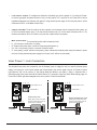
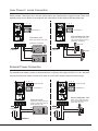
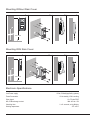
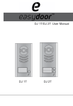
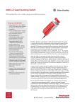
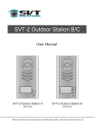
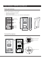
Door Camera - VDT591 User Manual
Parts and functions
The 591 is a special design for the 2-wire system:
• Full matel cover with backlight nameplate
• 4 Door cameras connection
• Directly connect 2 separate electronic locks, unlock time controlled by Monitor
Camera Lens
Speaker
Name
176 mm
Night View LED
Nameplate
Call Button
Microphone
90 mm
23 mm
Terminal Descriptions
1 2 3
ON
1 2
Camera Code DIP
1 2
ON
Lock Control Jumper
MIC adjustment
SPK adjustment
S2+ SPL S1+
L1 L2
Main Connect Port
1
• Lock Control Jumper: To configure the electronic lock safety type; set the jumper in 1-2 position for Powerto-Unlock type(pulse activated electronic lock), set the jumper in 2-3 position for the Power-Off-to-Unlock
type(electromagnetic lock). Remove the jumper if using external power supply for the lock.(the power+ will be
connected to the PL on the Main Connect Port)
• Camera Code DIP: To set the code for the door camera, total 4 cameras can be connected in the system; set
to 00 for the master camera, set to 10 for the slave 2nd camera, set to 01 for the slave 3rd camera, set to 11 for
the slave 4th camera. Set to 00 if there is only one door camera used in the system.
•
•
•
•
•
Main Connect Port: To connect the bus line and the electronic locks.
L1, L2: Connect to the bus line, no polarity.
PL: External lock power input, connect to the power positive(power +).
S1+, S2+: Lock power(+) output, to connect 2 electronic locks.
S-: Lock power(-) output, connect to the power(-) input of electronic locks(only when using the camera to power
the locks, if using the external power supply for the locks, the S- will not be connected)
Inner Power 1 Lock Connection
The standard inner power lock connection, use the Camera power to supply the lock, no need for external power
supply. In this way, the Lock Control Jumper and Unlock Mode in the monitor need to be set: for Power-to-Unlock
type electronic lock, set to position 1-2 and Unlock Mode 0(in Monitor, goto Main--> Setup--> Advanced Set-->
Information page, then press and hold the Unlock Button for 2 seconds to open the Unlock Mode setting page); for
Power-Off-to-Unlock type electromagnetic lock, set to position 2-3 and Unlock Mode 1.
1 2 3
1 2 3
ON
CALL
CALL
UNLOCK
UNLOCK
TALK/MON
IN-USE
MENU
L1 L2 PL S1+ S2+ S-
Unlock Mode: 0
TALK/MON
IN-USE
MENU
2
Unlock Mode: 1
Electronic lock
ElectronMagnetic lock
Safety Type: Power-on-to-open
The lock consumption must not
greater than 12V 500mA.
Safety Type: Power-off-to-open
The lock consumption must not
greater than 12V 500mA.
L1 L2 PL S1+ S2+ S-
to Monitor
1 2
ON
Jumper position in 2-3
1 2
Jumper position in 1-2
+
to Monitor
+
Inner Power 2 Locks Connection
Directly connect 2 electronic locks to the door station and use the Camera power to supply the locks. There are 2
separate unlock icons on Monitor for opening each lock. Note that the 2 locks should be the same safety type.
1 2 3
1 2 3
ON
1 2
Jumper position in 2-3
1 2
ON
Jumper position in 1-2
CALL
CALL
UNLOCK
TALK/MON
IN-USE
MENU
UNLOCK
Unlock Mode: 0
TALK/MON
IN-USE
MENU
ElectronMagnetic lock
Electronic lock
Safety Type: Power-on-to-open
The lock consumption must not
greater than 12V 500mA.
L1 L2 PL S1+ S2+ S-
to Monitor
L1 L2 PL S1+ S2+ S-
-
Safety Type: Power-off-to-open
The lock consumption must not
greater than 12V 300mA.
lock #2
-
lock #2
to Monitor
+
Unlock Mode: 1
+
lock #1
-
lock #1
+
+
External Power Connection
Use external power supply to power the electronical locks, in this way, wide range lock from 5V to 48 V electronic
locks can be used in the system. Note that in this case, the Lock Control Jumper is removed in both lock type.
1 2 3
1 2 3
Jumper removed
ON
CALL
CALL
UNLOCK
UNLOCK
TALK/MON
IN-USE
MENU
L1 L2 PL S1+ S2+ S-
Unlock Mode: 0
TALK/MON
IN-USE
MENU
L1 L2 PL S1+ S2+ S-
Safety Type: Power-on-to-open
The lock consumption must not
greater than 48V 1.5A.
to Monitor
+
Adaptor
Safety Type: Power-off-to-open
The lock consumption must not
greater than 48V 1.5A.
+
-
-
Unlock Mode: 1
ElectronMagnetic lock
Electronic lock
+
to Monitor
1 2
ON
1 2
Jumper removed
-
+
3
Mounting Without Rain Cover
1
2
3
4
3
4
1
2
160-165cm
Mounting With Rain Cover
1
2
1
2
160-165cm
Electronic Specifications
Lock Power supply:
12Vdc, 500mA(supplied by system)
Power Consumtion:
1W in standby, 12W in working
Video signal:
NO, COM exchange contact:
Unlocking time: Working temperature:
4
1Vp-p 75 ohm CCIR
Max. 48V dc 1.5A
1 to 9 seconds, set by Monitor
-5ºC +45ºC