1
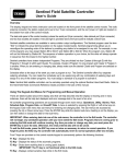
Remote Controller
User's Manual
HCT-820/HCR-4873
REMOTE CONTROLLER
Digital Remote Control System
USER’S
USER
S MANUAL
HCT-820 / HCR-4873
HANGIL CONTROL Co.,, Ltd.
Hangil Control Co., Ltd
1
2008-09-24
Remote Controller
User's Manual
HCT-820/HCR-4873
TABLE OF CONTENTS
1. INTRODUCTION ---------------------------- 2
2. FEATURES --------------------------------
2
3. CONFIGURATIONS -------------------------- 3
4 SPECIFICATIONS AND DRAWING --------------- 4
4.
5. INSTALLATION AND SETUP ------------------- 6
6. OPERATING PROCESS ----------------------- 9
7. OPERATING FLOWCHART --------------------
10
8. MAINTENANCE ----------------------------- 11
9. TROUBLESHOOTING GUIDE ------------------
12
10. CHARGER AND BATTERY ------------------- 13
Hangil Control Co., Ltd
2
2008-09-24
Remote Controller
User's Manual
HCT-820/HCR-4873
1. INTRODUCTION
1 1 Overview
1-1.
HC-820 is a wireless remote controller consisting of a portable transmitter, a receiver,
an antenna and rechargeable batteries
This is generally applicable to hoist cranes, gantry cranes, bogies and general industrial
machines.
1-2. Product Advantages
-
Improvement in Operation Efficiency
Working in Safety
Improvement in Working Environment
Reduction of Worker force
2. FEATURES
2-1. Multi-Frequency
Radio frequency (RF) of the transmitter and the receiver is changeable with simple action in the
job site
2-2. Auto Power-off Function
When the transmitter is not operation more than 3 minutes, power turned off to prevent
discharging of the battery
2-3. Water-proof,
p
, Dust-proof
p
and Wide Operating
p
g Temperature
p
Range
g
This transmitter has water-proof, dust-proof function and wide operating temperature ranges
from -30°C to +70°C.
2-4. Low-voltage Warning Function
When the transmitter’s battery is discharged lower than 4.5V, the battery (BAT) lamp blinks
twice per second
2-5. Assigned Own Code Number (Address Code)
Each transmitter has assigned own code number (Address Code) among 4,096 Electronic Key
Code Numbers to prevent any electronic interferences.
2-6. Enough Distance for Operation
The operating distance of transmitter is 70 meters which is enough to operate and be in safe
operation.
Hangil Control Co., Ltd
3
2008-09-24
Remote Controller
User's Manual
HCT-820/HCR-4873
3. CONFIGURATIONS
3 1 Basic Parts
3-1.
Transmitter (HCT-820) -------------------------------1 SET
Receiver (HCR-4873) ---- ---------------------------- 1 SET
Receiving Antenna (for 173MHz) ------------------------ 1 EA
Charger (HCG-4814) ---------------------------------1 EA
Rechargeable Battery (HCB-4814)
(HCB 4814) -----------------------1 PACK
3-2. Spare Parts
Rechargeable Battery (HCB-4814) -----------------------1 PACK
Fuse (250V 0.5A) ------------------------------------5 EA
S
5) --------------------------------------- 5 EA
Screws (3
(3*5)
PVC Cover for Case ----------------------------------1 EA
Hangil Control Co., Ltd
4
2008-09-24
Remote Controller
User's Manual
HCT-820/HCR-4873
4. SPECIFICATIONS AND DRAWING
4 1 Specifications
4-1.
TRANSMITTER
RECEIVER
HCT-820
HCR-4873
MODEL
FREQUENCY
173.6250 MHz ~173.7875 Mhz
TYPE of EMISSION
F2D
RF POWER
Under 5Mw & 10mW
RF BANDWIDTH
173 MHz
OSCILLATION METHOD
PLL / X-tal
MODULATION METHOD /
DATA TRANSFER RATE
MSK / 2400bps
INTERMEDIATE FREQUENCY
1 t : 21
650 MH
d : 450 kH
1st
21.650
MHz, 2
2nd
kHz
COMMUNICATION METHOD
SIMPLEX
NUMBER of CHANNELS
21 Channels (Frequency Separation: 12.5 kHz)
MULTIPLYING METHOD
2nd Mix (Multiplying 10.6 kHz * 2)
POWER AMPLIFIER
2 Stages
EMISSION
SS O ANGLE
G
360°
OPERATING TEMPERATURE
-30°C ~ +70°C
WEIGHT (GROSS)
1520g
30kg
INPUT POWER
DC4.8V(PACK)
AC85V~264V 50/60Hz
NOMINAL SWITCHING
CAPACITY
Hangil Control Co., Ltd
AC250V 5A
5
2008-09-24
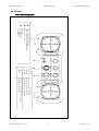
◀L
R
PWR: POWER ON LAMP(GRE
EEN)
BAT: LOW BATTERY CHECK
K NLAMP(RED)
T L
1
EMS S/W (PULL TYPE)
DESCRIPTION
2
KEY S/W
O: POWER OFF
I: POWER ON
S: SIREN ON
NO
3
F
T
S
LIGHT
SPARE
SPARE
O I S
D
M
H
U
EMS
3
◀D
A H
T L L,R
T S F,B
B
SLEW L,R
R
M H U,D
D
1 BUTTON 1 STEP PU
USH S/W
1 BUTTON 1 STEP PUSH
P
S/W(SELF HOLDING)
TRAVELLING 3 NOTC
CH LEVER S/W
TRAVERSING 3 NOTC
CH LEVER S/W
AUX HOIST 3 NOTCH
H LEVER S/W
MAIN HOIST 3 NOTC
CH LEVER S/W
U
LIGHT
DE
ESCRIPTION
SPARE
BUTTON SP
PEC
2
B
PW
WR BAT
1
◀
2008-09-24
6
Hangil Control Co., Ltd
◀
HCT-820/HCR-4873
User's Manual
Remote Controller
4-2. Drawing
- HCT-820 (Transmitter)
Remote Controller
User's Manual
HCT-820/HCR-4873
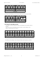
4-3.
4
3. Drawing
- HCR-4873 (Receiver)
SURGE KILLER
주권-하
주권-상
보권-하
보권-상
횡행 후
횡행-후
횡행 전
횡행-전
주행-우
주행-좌
SURGE KILLER
SURGE KILLER
SURGE KILLER
SURGE KILLER
Hangil Control Co., Ltd
7
2008-09-24
Remote Controller
User's Manual
HCT-820/HCR-4873
5. INSTALLATION AND SETUP
This equipment operates normally after wireless communications between the
transmitter and the receiver which is the same Frequency Channel and Address
Code.
5-1. Setup for the Radio Frequency (RF) Channel
The Radio Frequency (RF) channel must adjust the same frequency between
the transmitter and the receiver.
Open
p the case of the transmitter and the receiver; see the Channel Switch is
adjusted the same channel number according to the table as below.
*기기명:HCT-820
CHANNEL NO
설정 주파수(㎒)
10
1
0
0
173.6250
0
1
173.6375
0
2
173.6500
0
3
173.6625
0
4
173.6750
0
5
173.6875
0
6
173.7000
0
7
173.7125
0
8
173.7250
0
9
173.7375
0
A
173.7500
0
B
173 7625
173.7625
0
C
173.7750
0
D
173.7875
TOTAL
14 CH
NOTICE
DO NOT CHANGE the RF Channel and the Address Code Switch at Site
because of an Accident.
If Necessary to Change Any Switch, Contact Us (Engineering Departmaent)before Change.
If Any Abnormality or Problemis Found While Using the Transmitter and the Receiver,
Stop its Use
Use, and Call to your Local Dealer or Our Factory
Factory.
Hangil Control Co., Ltd
8
2008-09-24
Remote Controller
User's Manual
ON
1
HCT-820/HCR-4873
ON
2
3
4
1
2
10
3
4
1
CHANNEL
Eg. Refer to the settings of the Channel Switch and frequency as below.
ON
1
ON
2
3
4
1
2
10
3
4
1
CHANNEL
5-2. Setup for the Address Code
The address Code must adjust the same code between the transmitter and the
receiver
receiver.
Open the case of the transmitter and the receiver; see the Address Code
Switch is adjusted the same position.
ON
1
ON
2
3
100
4
1
ON
2
3
10
ADDRESS
4
1
2
3
4
1
Eg. Refer to the settings of the Channel Switch and frequency as below.
ON
1
ON
2
3
100
Hangil Control Co., Ltd
4
1
ON
2
3
4
10
ADDRESS
1
2
3
4
1
9
2008-09-24
Remote Controller
User's Manual
HCT-820/HCR-4873
6. OPERATING PROCESS
6-1. Starting for Transmitter and Receiver
-. Check the condition with these steps.
1) Open the case of the receiver and turn no the Power Switch.
2) Pull the red EMS(Emergency Stop Switch) button at the bottom of the
transmitter, and turn on the Key Switch to the siren('I' position).
WARNING
IN AN EMERGENCY, PUSH THE EMS (EMERGENCY STOP SWITCH0 BUTTON TO SHUT DOWN.
Operate after check the causes and remove them.
6-2. Operating for Transmitter and Receiver
1
2
3
4
5
6
Push
Push
Push
Push
Push
Push
or
or
or
or
or
or
pull
pull
pull
pull
pull
pull
the
the
the
the
the
the
lever
lever
lever
lever
lever
lever
in
in
in
in
in
in
the
the
the
the
the
the
direction
direction
direction
direction
direction
direction
of
of
of
of
of
of
"U"(Up) on the transmitter.
"D"(Down) on the transmitter.
"F"(Forward) on the transmitter.
"B"(Backward) on the transmitter.
"L"(LEFT) on the transmitter.
"R"(Right) on the transmitter.
The PWR lamp (green) on the
transmitter and the Relay's lamp
in the receiver blinks
blinks.
WARNING
-
Operating Only the Workers Being Trained as Operator’s Training Course.
Take Checkup and Training Regularly.
B Sure
Be
S
tto O
Operate
t th
the Sh
Shortest
t t Di
Distance
t
and
dS
See it th
the F
Freight
i ht iis L
Locked
k d iin S
Safety.
f t
See what the Crane and the Transmitter Move the Same Direction.
Never to Operate Out of Sight. (Be Sure to Operate in Sight of the Crane and the Freight.)
Hangil Control Co., Ltd
10
2008-09-24
Remote Controller
User's Manual
HCT-820/HCR-4873
7. OPERATING FLOWCHART
Insert the battery pack to the transmitter.
Pull the red EMS button at the button of the transmitter
transmitter, and
turn on the Key Switch to the right
PWR lamp (green) is Turned-on
Check the Siren Button
Operating the Transmitter
Push the red EMS button, and turn off the Key Switch to the left
The End of the Operating Transmitter
Hangil Control Co., Ltd
11
2008-09-24
Remote Controller
User's Manual
HCT-820/HCR-4873
8. MAINTENANCE
NOTICE
-
Checkup Every Functions One by One.
Replace the Worn Parts of the Transmitter and the Receiver Regularly.
Take Checkup Spare Parts Regularly.
If Replacing any Parts, Turn Off the Power.
Keep the Antistatic Bag the PCB of the Transmitter and the Receiver.
8-1. Weekly Maintenance
1.
2.
3.
4.
5
5.
6.
Check abrasion and operating condition of each Button Switches.
Operating condition of EMS (Emergency Stop Switch) Button.
Check any external abrasion of the transmitter.
Charging state of the batteries.
Checking life cycle of the batteries
batteries.
Contacting state of batteries.
8-2. Monthly Maintenance
Monthly Maintenance of the transmitter
1.Every Connectors state of every units.
2. Check foreign material or dust inside the transmitter
3 Broken state of the dust proof transmitter cover
3.
cover.
4. State of the battery case
8-3. Monthly Maintenance of the receiver
1.
2.
3.
4
4.
5.
6.
7.
8.
9.
Every Connectors state of every units.
Check foreign material or dust inside the receiver.
Joint state of the clamp screw of the receiver.
State of the output relay and the fuse
fuse.
Joint state of the output terminal board.
Joint state of the IC terminal pins.
Contact state of antenna
Operation state of each operation lamp.
The fixing state of all fixed dip switches.
Hangil Control Co., Ltd
12
2008-09-24
Remote Controller
User's Manual
HCT-820/HCR-4873
9. TROUBLESHOOTING GUIDE
1. PWR Lamp is Turned-off
1
Turned off but PWR Switch is Turned
Turned-on
on
2 Not Operating Transmitter but PWR Lamp is Turned-on
3. A function doesn't operate
4. BATTERY'S LIFETIME IS CONSIDERABLY REDUCED
5. Not Operating from a Distance
No.
1
ITEMS
PWR Lamp is Turned-off
but PWR Switch is
Turned-on
CAUSE
ACTION
Low Voltage of the Battery
Replace the Battery
Bad or Poor Connection in the
Transmitter or the Receiver
Check Connection
Bad or Poor Connection of
the Battery
Check Connection
Turn Off and Turn On the
Working in Auto Power-off Circuit EMS(Emergency Stop Switch) Button,
then Turn On the Power Switch
2
Turn On the Power Switch in the
Receiver
Breakdown of Fuse
Replace the Fuse
Bad Button
Replace the Button
Bad Relay
Replace the Relay
Bad or Poor Connection of the
Transmitter
Check or Replace the Bad Parts
contact failure of the transmitter
s/w
REPLACE CONNECTION PARTS
Not Operating Transmitter
but PWR Lamp is Turnedon
3
A function doesn't
doesn t
operate
4
BATTERY'S LIFETIME IS
CONSIDERABLY
REDUCED
5
Not Operating from a
Distance
6
Power Switch is Turned-Off in the
Receiver
OTHERS
Hangil Control Co., Ltd
RELAY OF RECEIVING POWER
DISCONNECTED
Bad or Poor Connection of
the Antenna
Check or Replace the Antenna
Bad RF Module
Replace the RF Module
EXAMINATION WITH THE NAKED
EYE
CHECK THE BROKEN PARTS BY A
SHOCK AND MAINTENANCE
NO CAUSES FOUND
REQUEST WARRANTY SERVICE
13
2008-09-24
Remote Controller
User's Manual
HCT-820/HCR-4873
10. CHARGER AND BATTERY
10 1 Features
10-1.
- Wide Range Voltage Battery Charging (AC100V~220V)
- High Capacity NiMH (Nickel Metal Hydride) Rechargeable Battery
(NiMH (Nickel Metal Hydride) batteries have high energy density and deliver up
to double the capacity of NiCd (Nickel Cadmium) batteries of similar size.)
- Indicate Battery Charging State with the LED Lamp
- Pack and Unpack Easily with the Coin Screw on the Battery
- Slim
Sli T
Type B
Battery
- High Reliability
10-2. Configurations
- Charger: HCG-4814 --------------------------------------- 1 EA
- Batteries: HCB-4814 <NiMH (Nickel Metal Hydride) Battery> ------- 2 Packs
- Adapter: AC100V~220V, 60Hz / DC12V 1A --------------------- 1 EA
10-3. Charge/Discharge Characteristics
-
Charging Time: about 2 hours
Discharge Capacity (Discharge Time): about 22 hours (at full charging)
Long Service Life: 300~1,000 charge/discharge cycles
Charging/Discharging Temperature: 0°C~40°C
0 C 40 C
10-4. Usage of the charger
1.
2.
3.
4.
Contact the power to AC 220V.
In put one battery to charger.
The red lamp light on to start charging.
The green lamp on when the charging goes 90%.
Please more charge for 1 hour.( full charging)
5. Please charge at – 10~40
6. If the batteries life time shorter than usual, push the discharge switch to discharge.
7. Look out the foreign material to the connection part.
8. Take careful the foreign material is at the bolt make them hard to move.
Hangil Control Co., Ltd
14
2008-09-24