1
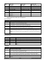
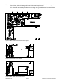
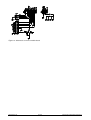
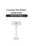
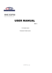
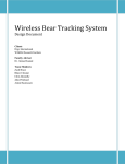
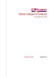
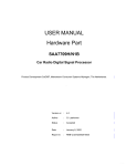
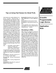
Hartcran House, 231 Kenton Lane, Harrow, Middlesex, HA3 8RP, England
Tel: +44 (0) 20 8909 9595, Fax: +44 (0) 20 8909 2233, www.radiometrix.com
NBEK
Narrow Band Module Evaluation Kit
Narrow Band Evaluation Kit (NBEK) can be
used to evaluate all Narrow Band Multichannel and Single frequency DIL version
modules. Radio modules can be assessed for
their suitability in terms of wireless operating
range, functionality, reliability and robustness
in a multi-user environment with several other
modules on different channels. Built in
Control44, I1200 modes allow user to evaluate
the performance of Radiometrix narrow band
modules in a typical Remote Control and data
transmission application in an industrial
environment.
Issue 1, 30 July 2012
Figure 1: Main controller board + xx2M series
carrier board
Features
RF module range testing
Noise and interference identification
Antenna type evaluation
Analogue and digital data transmission
4 Data channel remote control
1200 baud dumb modem
Setup is simple as Plug-and-Play
RS232 Serial port interface for frequency/channel configuration
RS232 Serial port interface for 1200 baud dumb modem
Access to internal diagnostic/Test modes using HyperTerminal
Access to each data/control pins for external interface or testing
Contents
2 Controller board
2 Carrier boards according to modules ordered separately
o BiM/SMX series (BiM1, NiM2, BiM2A, BiM3B, SMX1 and SMX2) carrier board
o xx2M series (TX1M/RX1M, TX2M/RX2M, TR1M and TR2M) carrier board
o LM series (LMT1/LMR1 and LMT2/LMR2) carrier board
o TLC2H /RLC2H and HVR2 carrier board
o SIL series modules (e.g. HX1, NTX2 / NRX2, TX3H/RX3A etc.) carrier board
o USX / UHX carrier boards
1 Pair of Radiometrix multichannel or single frequency TX/RX or transceivers (ordered separately)
2 9V alkaline battery (PP3)
10 Jumpers
1 Narrow Band Evaluation Kit manual
1 Data sheet of Radio module ordered
2 1/4 wavelength monopole antenna with BNC connector for 433MHz operation
2 Helical antennas with BNC connector for 151MHz / 173MHz (optional)
Radiometrix Ltd
Page 1
Narrow Band Evaluation Kit Manual
Configuring the Narrow Band Multi-channel Evaluation Kit
One of the Evaluation Kit should be assigned as transmitter and other as receiver.
Jumpers on the main controller board
LK1
Inserted
Removed
LK2
D0
D1
D2
D3
Connects R1=2.2kΩ across TXD and GND pins
R18=1.5kΩ in series with TXD.
3V CMOS Data Input to Transmitter. Only being fitted for 3VPk-Pk input only modules
(BiM1, NiM2, TX1, NTX2 etc)
5V CMOS Data Input to Transmitter
Jumper inserted: 0V (logic ‘0’) and LED ON; Jumper removed: 5V (logic ‘1’)
Selects Data Bit0 value during Control44 encoder mode
Selects Data Bit1 value during Control44 encoder mode
Selects Data Bit2 value during Control44 encoder mode
Selects Data Bit3 value during Control44 encoder mode
Jumpers on the carrier board:
XX2M series
LK3
LK4
LK5
Slide yellow coloured switches to ON position marked by arrow for TX1M, TX2M
Remove for RX1M, RX2M, TR2B, TR2M
TXE from controller routed to TXE pin on TX2M (SQF pin on RX2M, TR2M)
TXD from controller routed to TXD pin on TX2M, (AFOUT pin on RX2M, TR2M)
AFIN from controller routed to AFIN pin on TX2M (RXD pin on R2M, TR2M)
Switches
MODE
(yellow)
0
1
2
3
4
5
6
7
8
9
A
B
C
D
E
F
H=VDD L=0V (inverted logic)
M3 M2 M1 M0
HHHH
Receiver ON
HHHL
Un-modulated Transmission for testing carrier frequency, power, spurii
HHLH
250Hz (500bps) square wave Modulated Transmission
HHLL
1250Hz (2.5kbps) square wave Modulated Transmission
HLHH
Pseudorandom NRZ stream modulated Transmission
HLHL
Transmitter and Receiver turned ON and OFF periodically at 100ms interval
HLLH
RESERVED for future use
HLLL
RESERVED for future use
LHHH
Continuous Control44 Transmission of Address=0 and Data=D3, D2, D1, D0
LHHL
Control44 Transmission of Address=0 and Data=D3, D2, D1, D0
If either Data is changed or RESET (Trigger) switch is pressed.
LHLH
Control44 Reception with Momentary Output. (paired with Mode 8)
LHLL
Control44 Reception with Latched Output. (paired with Mode 9)
LLHH
Transmits CTR44 Test Packet, Receive Echoed Packet (Radar Mode – Master)
LLHL
Receive CTR44 Test Packet, Re-transmit it back to Sender (Echo Mode – Slave)
LLLH
I1200 type 1200 baud Dumb Modem for bit balanced serial data transmission
LLLL
RESERVED for future use
Notes:
1. Mode C, D require Transceiver
2. In Mode C, a test packet is transmitted, then the unit switches to Receive mode for 100ms before
repeating.
3. Data sequence of 8 (D3=L, D2=H, D1=H, D0=H), 4, 2, 1 (D3=H, D2=H, D1=H, D0=L) is cycled
through with each transmission.
4. In Mode D, the unit idles in Receive mode. When a valid CTR44 burst is received the unit keys up
the Transmitter and re-transmits this CTR44 burst back to sender in Mode C.
5. The 'modem' mentioned (Mode E) is a 1200 baud RS232 semi-intelligent unit (Transmit keyed when
valid serial data is present, so no separate TX control needed. Coding in the datastream also permits
the receiver to ignore noise and only output valid serial data). This is a half duplex unit, so collisions
between transmitted and received packets must be dealt with by the user.
Radiometrix Ltd
Page 2
Narrow Band Evaluation Kit Manual
CHANNEL
(blue)
0
1
2
…..
7
8
xx2M, SMX
H=4V, L=0V
Hex Switch
P2=H, P1=H, P0=H
P2=H, P1=H, P0=L
P2=H, P1=L, P0=H
……
P2=L, P1=L, P0=L
Not in Use (Appears as
Channel 0)
LM Series Units
H=3V, L=0V
Hex Switch
P3=H P2=H, P1=H, P0=H
P3=H, P2=H, P1=H, P0=L
P3=H, P2=H, P1=L, P0=H
TLC/RLC/HVR
H=3.5V, L=0V
Hex Complement Switch
P3=L, P2=L, P1=L, P0=L
P3=L, P2=L, P1=L, P0=H
P3=L, P2=L, P1=H, P0=L
P3=H, P2=L, P1=L, P0=L
P3=L, P2=H, P1=H, P0=H
P3=L, P2=H, P1=H, P0=H
P3=H, P2=L, P1=L, P0=L
……
E (14)
Not in Use (Appears as
P3=L, P2=L, P2=L, P0=H
P3=H, P2=H, P1=H, P0=L
Channel 6)
F (15)
Not in Use (Appears as
P3=L, P2=L, P1=L, P0=L
P3=H, P2=H, P1=H, P0=H
Channel 7)
Note: channel switch to be set to 0 (LMR, LMT) or F (RLC, TLC, HVR) when serial (RS232)
programming the unit, as 'P0' is also 'serial program in'.
User Test Points
Pin
5V
AFIN
TXD
TXE
RXD
AFOUT
SQF
RSSI
Description
5V, 1A Low Dropout Voltage Regulator Output
Transmit Input for 1Vpk-pk Audio Frequency (Analogue) Signal using TX1M, TX2M, TR2M
Set to MODE 1, to feed external Analogue Signal
Transmit Input for Digital (Binary) Data driven by onboard microcontroller
Set to MODE 1, to feed external 5V CMOS level Digital Data
Active Low Transmit Enable driven by onboard microcontroller
Received (Digital) Data Output from Radio Module
Open Collector output from module pulled up to 5V using R4=10kΩ
Audio Frequency (Demodulated Buffered Analogue) Signal
Active Low Squelch Function when RF Carrier is not present
Open Collector output pulled up to 5V using R1=22kΩ on RX1M, RX2M, TR2M Carrier
Board
Connected to Q5 (NPN transistor) via R4=330kΩ base resistor to turn on Carrier Detect
LED.
Received Signal Strength Indicator
Visual Indicators
LED
D0
D1
D2
D3
STATUS
ON
CD
Colour
Red
Red
Red
Red
Bright Yellow
Green
Bright Orange
Description
Data Bit0 output indicator during Control44 decoder mode
Data Bit1 output indicator during Control44 decoder mode
Data Bit2 output indicator during Control44 decoder mode
Data Bit3 output indicator during Control44 decoder mode
STATUS indicator – Transmitter Active or Valid Data received
Evaluation Kit powered with correct polarity power supply
Carrier Detect indicator for RX1M, RX2M or TR2M derived from SQF
output
Connectors
Pin
DC socket
PROG
MODEM
PP3 SNAP
SIL socket
Radiometrix Ltd
Description
2.1mm power socket; when a power supply jack is inserted, a mechanical switch
disconnects the battery negative
Connect to COM port of a PC using straight DB9M-DB9F serial cable to configure the
channel and frequency of a multichannel module
Hyper Terminal setting: 2400 baud, none parity, 8 data bits, 1 stop bit, none flow control
Connect to COM port of a PC using straight DB9M-DB9F serial cable to evaluate serial
data transmission through a radio module using onboard 1200 baud dumb modem.
Hyper Terminal setting: 1200 baud, none parity, 8 data bits, 1 stop bit, none flow control
8.4V NiMH or 9V Alkaline PP3 type battery
Appropriate radio module carrier board is inserted into the socket and secured with 4 short
spacers
Page 3
Narrow Band Evaluation Kit Manual
Note:
The carrier board should always be firmly bolted down to the main controller board mounting studs at
all four corners, or the grounding of the carrier board will be compromised.
This is especially important when high power transmitters are used with the aerial connected directly
onto the BNC. In this case, any mismatch will cause significant ground currents to flow.
Figure 2: Main controller board component layout
Figure 3: xx2M series carrier board
Figure 4: BiM / SMX series carrier board
Radiometrix Ltd
Page 4
Narrow Band Evaluation Kit Manual
Figure 5: LM series carrier board
Figure 6: TLC2H/RLC2H and HVR2 carrier board
Figure 7: SIL series module carrier board
Figure 8: MSR or COR series module carrier board
Radiometrix Ltd
Page 5
Narrow Band Evaluation Kit Manual
Figure 8: UHX1 module carrier board
Figure 9: USX2 module carrier board
Radiometrix Ltd
Page 6
Narrow Band Evaluation Kit Manual
Radiometrix Ltd
Page 7
Narrow Band Evaluation Kit Manual
Figure 10: Schematics of main controller board
Radiometrix Ltd
Page 8
Narrow Band Evaluation Kit Manual
Narrow band Eval Kit controller IC
The NBEK controller IC can also be ordered separately with equal number of radio modules.
TXD
NC
STATUS
TXE
OSC1
RESET
OSC2
Vss (0V)
Remote control
Data bits
serial data I/O
RXD
Vdd
D0
M3
RSTXD/D1
M2
mode select bits
M1
M0
D3
Figure 11: NBEK-000-DIL pinouts
Ordering Information (IC):
NBEK-000-SS - Shrink Small Outline
NBEK-000-SO - Small Outline
NBEK-000-DIL - Plastic Dual In Package
Radiometrix Ltd
Page 9
Narrow Band Evaluation Kit Manual
Radiometrix Ltd
Hartcran House
231 Kenton Lane
Harrow, Middlesex
HA3 8RP
ENGLAND
Tel: +44 (0) 20 8909 9595
Fax: +44 (0) 20 8909 2233
[email protected]
www.radiometrix.com
Copyright notice
This product data sheet is the original work and copyrighted property of Radiometrix Ltd. Reproduction in
whole or in part must give clear acknowledgement to the copyright owner.
Limitation of liability
The information furnished by Radiometrix Ltd is believed to be accurate and reliable. Radiometrix Ltd
reserves the right to make changes or improvements in the design, specification or manufacture of its
subassembly products without notice. Radiometrix Ltd does not assume any liability arising from the
application or use of any product or circuit described herein, nor for any infringements of patents or other
rights of third parties which may result from the use of its products. This data sheet neither states nor
implies warranty of any kind, including fitness for any particular application. These radio devices may be
subject to radio interference and may not function as intended if interference is present. We do NOT
recommend their use for life critical applications.
The Intrastat commodity code for all our modules is: 8542 6000
R&TTE Directive
After 7 April 2001 the manufacturer can only place finished product on the market under the provisions of
the R&TTE Directive. Equipment within the scope of the R&TTE Directive may demonstrate compliance
to the essential requirements specified in Article 3 of the Directive, as appropriate to the particular
equipment.
Further details are available on The Office of Communications (Ofcom) web site:
http://www.ofcom.org.uk/
Information Requests
Ofcom
Riverside House
2a Southwark Bridge Road
London SE1 9HA
Tel: +44 (0)300 123 3333 or 020 7981 3040
Fax: +44 (0)20 7981 3333
[email protected]
European Communications Office (ECO)
Peblingehus
Nansensgade 19
DK 1366 Copenhagen
Tel. +45 33896300
Fax +45 33896330
[email protected]
www.ero.dk