1
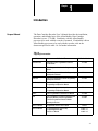
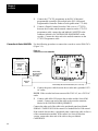
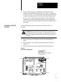
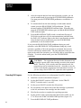
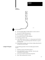
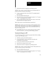
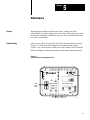
AllenBradley
Data Cartridge
Recorder
(Cat. No.
1770SB)
User Manual
Table of Contents
Introduction . . . . . . . . . . . . . . . . . . . . . . . . . . . . . . . . . . . .
11
Scope of Manual . . . . . . . . . . . . . . . . . . . . . . . . . . . . . . . . . . . .
General Information . . . . . . . . . . . . . . . . . . . . . . . . . . . . . . . . . .
Data Cartridge . . . . . . . . . . . . . . . . . . . . . . . . . . . . . . . . . . . . . .
Marking Tapes . . . . . . . . . . . . . . . . . . . . . . . . . . . . . . . . . . . . . .
Data Cartridge Repacking . . . . . . . . . . . . . . . . . . . . . . . . . . . . . .
Importance of Verification . . . . . . . . . . . . . . . . . . . . . . . . . . . . . .
11
12
12
13
14
14
Recorder Hardware . . . . . . . . . . . . . . . . . . . . . . . . . . . . . .
21
General Description . . . . . . . . . . . . . . . . . . . . . . . . . . . . . . . . . .
Switches . . . . . . . . . . . . . . . . . . . . . . . . . . . . . . . . . . . . . . . . . .
Indictors . . . . . . . . . . . . . . . . . . . . . . . . . . . . . . . . . . . . . . . . . .
Data Interface . . . . . . . . . . . . . . . . . . . . . . . . . . . . . . . . . . . . . .
230 V Fuse Kit . . . . . . . . . . . . . . . . . . . . . . . . . . . . . . . . . . . . . .
21
21
21
21
22
Installation . . . . . . . . . . . . . . . . . . . . . . . . . . . . . . . . . . . . .
31
General . . . . . . . . . . . . . . . . . . . . . . . . . . . . . . . . . . . . . . . . . . .
Connection to PLC Programmable Controllers . . . . . . . . . . . . . . .
Connection to PLC2 Family and PLC3 Programmable Controller
and Series 7100 CNCs . . . . . . . . . . . . . . . . . . . . . . . . . . . . .
Connection to PLC4 Microtrol Programmable Controllers . . . . . . .
Connection to Series 8200 CNCs . . . . . . . . . . . . . . . . . . . . . . . .
Converting for 230 V AC Operation . . . . . . . . . . . . . . . . . . . . . . .
31
31
32
33
34
35
Operation . . . . . . . . . . . . . . . . . . . . . . . . . . . . . . . . . . . . .
41
General . . . . . . . . . . . . . . . . . . . . . . . . . . . . . . . . . . . . . . . . . . .
Recording PLC Programs . . . . . . . . . . . . . . . . . . . . . . . . . . . . . .
Loading PLC Programs . . . . . . . . . . . . . . . . . . . . . . . . . . . . . . .
Verifying PLC Programs . . . . . . . . . . . . . . . . . . . . . . . . . . . . . . .
Recording PLC2 Family Programs . . . . . . . . . . . . . . . . . . . . . . .
Loading PLC2 Family Programs . . . . . . . . . . . . . . . . . . . . . . . . .
Verifying PLC2 Family Programs . . . . . . . . . . . . . . . . . . . . . . . .
Recording PLC3 Programs . . . . . . . . . . . . . . . . . . . . . . . . . . . .
Loading PLC3 Programs . . . . . . . . . . . . . . . . . . . . . . . . . . . . . .
Verifying PLC3 Programs . . . . . . . . . . . . . . . . . . . . . . . . . . . . .
Recording PLC4 Microtrol Programs . . . . . . . . . . . . . . . . . . . . . .
Loading PLC4 Microtrol Programs . . . . . . . . . . . . . . . . . . . . . . .
Verifying PLC4 Microtrol Programs . . . . . . . . . . . . . . . . . . . . . . .
Recording Series 7100 CNC Programs . . . . . . . . . . . . . . . . . . . .
Loading Series 7100 CNC Program . . . . . . . . . . . . . . . . . . . . . . .
Verifying Series 7100 CNC Programs . . . . . . . . . . . . . . . . . . . . .
41
42
43
45
45
46
47
47
410
411
411
412
413
413
414
415
ii
Table of Contents
Recording Series 8200 CNC Part Programs . . . . . . . . . . . . . . . . .
Reading Series 8200 CNC Part Programs . . . . . . . . . . . . . . . . . .
Recording Series 8200 CNC PAL Programs . . . . . . . . . . . . . . . . .
Loading Series 8200 CNC Pal Programs . . . . . . . . . . . . . . . . . . .
Recording Series 8200 CNC Executive Programs . . . . . . . . . . . . .
Loading Series 8200 CNC Executive Programs and PAL
Binary Programs . . . . . . . . . . . . . . . . . . . . . . . . . . . . . . . . . .
Recording Series 8200 AMP or Diagnostics Utility Programs . . . . .
Load AMP From Cassette to 8200 CNC . . . . . . . . . . . . . . . . . . . .
Load Diagnostics From Cartridge to 8200 CNC . . . . . . . . . . . . . . .
Erasing Series 8200 Programs . . . . . . . . . . . . . . . . . . . . . . . . . .
415
417
420
421
422
Maintenance . . . . . . . . . . . . . . . . . . . . . . . . . . . . . . . . . . .
51
General . . . . . . . . . . . . . . . . . . . . . . . . . . . . . . . . . . . . . . . . . . .
Head Cleaning . . . . . . . . . . . . . . . . . . . . . . . . . . . . . . . . . . . . . .
Unit Cleaning . . . . . . . . . . . . . . . . . . . . . . . . . . . . . . . . . . . . . . .
Head Demagnetizing . . . . . . . . . . . . . . . . . . . . . . . . . . . . . . . . .
Data Cartridge Storage . . . . . . . . . . . . . . . . . . . . . . . . . . . . . . . .
51
51
52
52
52
Specifications . . . . . . . . . . . . . . . . . . . . . . . . . . . . . . . . . .
61
423
424
424
425
426
Chapter
1
Introduction
Scope of Manual
The Data Cartridge Recorder User’s Manual describes the installation,
operation, and intended uses of the Allen-Bradley Data Cartridge
Recorder (cat. no. 1770-SB). Familiarity with the Allen-Bradley
processor to be used with the recorder is assumed. If unfamiliar with an
Allen-Bradley processor to be used with the recorder, refer to the
document specified in table 1.A for further information.
Table 1.A
Supporting Documentation
Processor
Publication Tile
Publication Number
PLC4 Microtrol
PLC4 Microcontrol Programmable Controller
Product Guide
1773800
PLC3
PLC3 Programmable Controller Programming
Manual
1775801
PLC2/30
PLC2/30 Programmable Controller Programming
and Operations Manual
1770806
PLC2/20
PLC2/20 Programmable Controller Programming
and Operations Manual
1772802
MiniPLC2/15
MiniPLC2/15 Programmable Controller
Programming and Operations Manual
1772804
MiniPLC2
MiniPLC2 Programmable Controller
Programming and Operations Manual
1772821
PLC2
PLC2 Programmable Controller User's Manual
1772800
PLC
PLC Programmable Controller Programming and
Operations Manual and PLC Programmable
Controller Program Panel Interface Module
Operating Instructions
1774800
1774817
Series 7100 CNC
Programmable Interface User's Guide
71004.2
Series 8200 CNC
Programming Manual (2axis Lathe)
Programming Manual (Mill)
Robot User's Manual
82005.2.1
82005.2.3
82005.2.4
11
Chapter 1
Introduction
General Information
The Data Cartridge Recorder is a portable, light-weight, recording device.
The recorder is used to load user programs into and record the contents of
memories of Allen-Bradley PLC, PLC-2 Family, PLC-3 and PLC-4
Programmable Controllers; and Series 7100 and Series 8200
Computerized Numerical Controllers, and Series 8200 Robot Control.
NOTE: Although programs can be duplicated from one tape to another,
Allen- Bradley does not recommend this practice because there is no
verification of programs when you duplicate the program. If an error
occurs during the duplication, you may not be able to load the tape.
There are several reasons for recording a user program, including:
Providing a dependable back-up to processor memory.
Allowing off-line storage for multiple programs, including diagnostic
programs.
WARNING: Never use diagnostic programs when the
processor is on line. Unintended machine motion may occur
causing possible equipment damage and/or injury to personnel.
Providing a source or valid record when temporary modifications to a
program are required.
Allowing identical programs to be used on several machines.
Series B data cartridge recorders may also transmit and receive programs
in the manual mode. In this mode, all control lines are disabled. Data is
transmitted over a 3-conductor cable.
The manual mode of operation makes the recorder compatible with both
the XL2 and XL3 translator packages.
Refer to publication 6004-800 for use with the XL2 translator package.
Refer to publication 6005-800 for use with the XL3 translator package.
Data Cartridge
12
The data cartridge recorder uses the Allen-Bradley Mini Data Cartridge
(cat. no. 1770-XJ). The mini data cartridge is shown in figure 1.1. It is a
2-track magnetic tape storage medium. Each track stores 72K words
(max) (K-1024). Compatible tapes must conform to ANSI X3.48-1977.
Chapter 1
Introduction
The contents of the mini-data cartridge can be protected using the
RECORD tab (Figure 1.1). If the tab is positioned to the right, the tape is
protected. If the tab is positioned to the left, the tape is unprotected and
can be recorded on.
Figure 1.1
Mini Data Cartridge
RECORD
CAT. NO. 1770XJ
MINI DATA CARTRIDGE
10014
Marking Tapes
When a program is recorded, you should mark the following information
on the blank data cartridge information label provided with each cartridge.
Tape name
file name
Program identification
Processor identification
Memory size
Data table size
Date
If multiple programs are recorded on one data cartridge, this information
must be supplied for each program. List programs in the order that they
appear on tape and list the track used for each program. It is important
that this information be clearly marked on the data cartridge. Individuals
unfamiliar with the contents of the tape will need this information to use
the programs.
13
Chapter 1
Introduction
Data Cartridge Repacking
Before inserting a data cartridge into the recorder, verify that the power
ON/OFF switch is in the ON position. This ensures that when the
cartridge is inserted, an automatic repacking operation is initiated. The
repacking operation involves a fast forward to the EOT (end of tape)
marker, and a fast reverse to the BOT (beginning of tape) marker. This
operation improves the reliability of program recording and loading. If
the power ON/OFF switch is turned on after the cartridge has been
inserted, the tape will not be repacked.
Importance of Verification
Verifying that programs are properly transferred between the recorder and
the processor is extremely important. A program which contains errors
due to the data transfer has little value.
Errors in transmission can be caused by many factors, including loose
connections, faulty cables, and electrical noise. If errors are found after
loading a program into the processor memory, you have two options:
The program can be re-loaded
An Industrial Terminal (cat. no. 1770-T1,-T2,-T3,-T4) can be used to
locate and correct the error
If errors are found after recording the contents of the processor memory,
the only practical option is to repeat the record operation.
Another use of the recorder’s verification feature is to check the contents
of an improperly marked tape. If the suggestions of section 1.3 are
followed, this should not be necessary.
14
Chapter
2
Recorder Hardware
General Description
This chapter describes the various switches, indicators, connectors, and
labels associated with the Allen–Bradley data cartridge recorder.
Switches
There are six switches on the recorder. Figure 2.1 shows the position of
the switches on the recorder front panel. Table 2.A lists switch functions.
Figure 2.1
Data Cartridge Recorder Front Panel
POWER
10846I
Indictors
There are ten LED indicators on the recorder. Figure 2.1 shows the
position of these indicators on the recorder front panel. Table 2.B lists
indicator functions.
Data Interface
The data cartridge recorder interfaces with Allen–Bradley products
through a 25–pin RS–232–C connector labeled A–B CONTROLLER
EQUIPMENT. This connector attaches to one end of a Cassette Recorder
Interconnect Cable (cat. no. 1774– TD), or a Digital Cassette Recorder
Cable (cat. no. 1772–TH).
The other end of the cable attaches to the Allen–Bradley product used
with the recorder. Installation with specific products is described in
chapter 3.
21
Chapter 2
Recorder Hardware
Table 2.A
Data Cartridge Recorder Switches
Name
Function
POWER ON/OFF
Toggle switch. Turns recorder power on or off.
BAUD RATE
Rotary switch. Selects 300, 600, 1200, 2400, 4800 or 9600 baud
operation.
TRACK SELECT
Rotary switch. Selects track 1, track 2, or continuous operation.
READ FROM TAPE
Momentary action pushbutton switch. Puts the recorder into the READ
mode.
RECORD ON TAPE
Momentary action pushbutton switch. Puts the recorder into the
WRITE mode.
STOP/REWIND
Momentary action pushbutton switch. Used to exit READ or WRITE
mode. When the tape is stopped, the switch initiates a rewind to the
Beginning Of Tape (BOT) mark.
Table 2.B
Data Cartridge Recorder Indicators
Name
230 V Fuse Kit
Indication
POWER
Power is applies to the recorder and the toggle switch is in the ON
position.
STOP/REWIND
Tape is repacking or rewinding.
BOTH TRACKS USED
TRACK SELECT switch is in CONT position and current operation
(READ, WRITE or IDLE) is on track 2.
END OF TRACK
Tape has reached the end of track 1 or track 2. Illuminates between
tracks and at the end of track 2 in continuous operation.
DATA IN
Recorder is receiving data.
DATA ERROR
Recorder has failed an attempted operation.
DATA OUT
Recorder is transmitting data.
RECORD ON TAPE
Recorder is in the WRITE mode.
WRITE INHIBITED
Data cartridge is protected. Data can not be recorded.
READ FROM TAPE
Recorder is in the READ mode.
The data cartridge recorder includes a 230V AC fuse kit for conversion to
230V AC operation. The fuse kit includes:
Instructions for converting to 230V AC operation
A 230V, 0.25A fuse
A 230V AC label
The recorder does not come with a 230V AC power cord. Therefore, the
power cord must be changed for 230V AC operation.
22
Chapter
3
Installation
General
PLC programmable controllers connect directly to the data cartridge
recorder. Other Allen-Bradley products connect to an Industrial Terminal
System (cat. no. 1770-T1,-T2,-T3,-T4), or a 1770-T12 programmer which
provides the interface with the recorder. This section describes both types
of installation. Table 3.A shows the cables used to connect the recorder to
other Allen-Bradley products.
Table 3.A
Cables for Connecting the Data Cartridge Recorder to Other AllenBradley Products
Product Connected to
the Data Cartridge
Recorder
Connection to PLC
Programmable Controllers
Cable
Cat. No.
PLC
Cassette Recorder Interconnect Cable
1774TD
Industrial Terminal
System
Digital Cassette Recorder Cable
1772TH
PLC4 Microtrol
Digital Cassette Recorder Cable
1772TH
Digital Cassette
Recorder
Digital Cassette Recorder Cable
1772TH
PLC4 Microtrol
Digital Cassette Recorder Cable
1772TH
Series 8200 CND
Cassette Recorder Interconnect Cable
8200CS
Use the following procedure to connect the recorder to PLC
programmable controllers (Figure 3.1).
1.
Connect the power cable between the recorder and a grounded 115V
AC outlet.
NOTE: If the recorder has been converted to 230V AC operation, use a
230V AC outlet.
2.
Connect a Cassette Recorder Interconnect Cable (cat. no. 1774-TD)
between the recorder and the PLC programmable controller.
Connect the end labeled CASSETTE to the connector labeled A-B
CONTROLLER EQUIPMENT on the recorder. Connect the 41-pin
connector to the Program Panel Interface Module (cat. no. 1774-TB,
-TB2) or the On-line Programming Module (cat. no. 1774-TL2).
31
Chapter 3
Installation
Figure 3.1
Connection to a PLC Programmable Controller
PLC Processor
Program
Panel
Interface
Module
POWER
Cassette Recorder Interconnect Cable
(Cat. No. 1774TD)
Connection to PLC2 Family and
PLC3 Programmable Controller
and Series 7100 CNCs
10376
PLC-2 Family and PLC-3 programmable controllers and series 7100
CNCs require an industrial terminal system connected between the
controller and the recorder. Connect the industrial terminal system to the
controller as described in the Industrial Terminal Systems User’s Manual,
publication 1770-805. Connect the recorder to the industrial terminal
system using the following procedure (Figure 3.2):
Figure 3.2
Connection to an Industrial Terminal System
POWER
Channel C
PLC2 Family
Processor or
Series 7100 CNC
32
PLC3 Processor
Digital Cassette
Recorder Cable
(Cat. No. 1772TH)
10378
Chapter 3
Installation
1.
Connect the power cable between the recorder and a grounded 115V
AC outlet.
NOTE: If the recorder has been converted for 230V AC operation, use a
230V AC outlet.
2.
Connection to PLC4 Microtrol
Programmable Controllers
Connect a Digital Cassette Recorder Cable (cat. no. 1772-TH)
between the recorder and the industrial terminal system. Connect the
end labeled CASSETTE to the connector labeled A-B
CONTROLLER EQUIPMENT on the recorder. Connect the other
end to the connector labeled CHANNEL C on the industrial terminal
system.
Use the following procedure to connect the recorder to PLC-4 Microtrol
programmable controllers (Figure 3.3).
1.
Connect the power cable between the recorder and a grounded 115V
AC outlet.
NOTE: If the recorder has been converted for 230V AC operation, use a
230V AC outlet.
Figure 3.3
Connection to a PLC4 Microtrol Programmable Controller
PLC4
Microtrol
PLC4
Microtrol
POWER
Digital Cassette
Recorder Cable
(Cat. No. 1772TH)
11296
33
Chapter 3
Installation
2.
Connect the 1770-T12 programmer to the PLC-4 Microtrol
programmable controller as described in the PLC-4 Microtrol
Programmable Controller Product Guide (publication 1773-800).
3.
Connect a Digital Cassette Recorder Cable (cat. no. 1772-TH)
between the recorder and the unused connector on the 1770-T12
programmer cable. connect the end labeled CASSETTE to the
connector labeled A-B CONTROLLER EQUIPMENT on the
recorder. Connect the other end to the unused connector on the
1770T12 Programmer cable.
Connection to Series 8200 CNCs Use the following procedure to connect the recorder to series 8200 CNCs
(Figure 3.4):
Figure 3.4
Connection to a Series 8200 CNC
8200 Processor
Communication
Interface
Module
(cat. no.
8000KAC_)
POWER
Data Cartridge
Recorder Internal
Cable (cat. no.
800032KH)
Peripheral
Panel
Data Cartridge Recorder External Cable (cat. no. 8000CS)
1.
11295
Connect the power cable between the recorder and a grounded 115V
AC outlet.
NOTE: If the recorder has been converted for 230V AC, use a 230V AC
outlet.
2.
Connect cable 8000-CS between the recorder and the Series 8200
control. Connect one end of the cable to the recorder connector
labeled A-B CONTROLLER EQUIPMENT.
Connect the other end of the cable to the peripheral panel port labeled
SERIAL 1/TAPE PUNCH if the control is a standard Series 8200 control.
If the control does not have a peripheral panel, connect the cable to Port A
of the communication module. If the control is a Series 8200 robot
version, connect the other end of the cable to the port labeled
CARTRIDGE.
34
Chapter 3
Installation
3.
Converting for 230 V AC
Operation
Set the control’s baud rate of 9600 baud. The baud rate can be
changed by altering the bits of PAL table 161, index 0. Change bits
2,1,0 to a value of 1,1,0. Do not alter the other bits in index 0 as they
control the communications between the control and its peripheral
devices. if the executive tape being used does not have PAL edit
capabilities, you will not be able to change or set the control baud
rate. If you do not have this capability, contact the OEM and request
the change.
Use the following procedure to convert the recorder for 230V AC
operation:
WARNING: Power must be moved from the recorder before
converting for 230V AC operation. Performing the conversion
with power applied to the recorder may cause serious injury to
personnel.
1.
Remove the power cord from the recorder and the grounded AC
outlet.
2.
Remove the four screws which attach the front panel to the case
(Figure 3.5).
3.
Disconnect the ground wire from the bottom of the front panel.
Figure 3.5
Converting to 230V Operation
230 VAC 1/4A SB
50/60 HZ 3AG
When using unit for 230 volt operation,
use the above label.
Screw
ON
115V 5060 HZ 5A SB
3 AMP
3 AG
Screw
OFF
BULLETIN 1770
POWER
STOP REWIND
BOTH
END OF
TRACKS USED TRACK
IN ERROR OUT
DATA
Screw
WRITE
INHB
RECORD
READ
ON
FROM
TAPE
TAPE
DATA CARTRIDGE RECORDER
1
2
1200
CONT 600
300
TRACK
SELECT
2400
4800
9600
BAUD
RATE
CONTROLLER
EQUIPMENT
Screw
11294
35
Chapter 3
Installation
4.
Remove the front panel from the case.
5.
Position the switch on the power supply (Figure 3.6) to the position
labeled 230.
6.
Reconnect the ground wire and front panel.
7.
Replace the fuse with a 0.25A slow blow 3AG fuse (included in the
2130V AC fuse kit).
8.
Place the 230V AC label over the existing voltage label (Figure 3.5).
9.
Replace the power cord or modify it for 230V AC operation by
replacing the plug.
Figure 3.6
Power Supply Switch Position
115/230V ac Switch
36
10859I
Chapter
4
Operation
General
The data cartridge recorder can be used to record programs at anytime.
However, to provide a backup which contains proper data for startup, it is
advisable to record the program before the process is started (while the
processor is still in the program load mode). This chapter describes the
steps required to operate the recorder with other Allen-Bradley products.
Table 4.A summarizes the baud rate switch settings.
Table 4.A
Baud Rate Switch Settings
Processor
Baud Rate Switch
Position
PLC
1200
PLC2 Family
1200
PLC3
9600
PLC4 Microcontrol
1200
Series 7100 CNC
1200
Series 8200 CNC
9600
NOTE: In most applications the data cartridge recorder is used in the
same manner as the Digital Cassette Recorder (cat. no. 1770-SA).
Manual Mode
Use the data cartridge recorder in the manual mode allows the recorder to
be compatible with the XL2 and XL3 translator packages. In the manual
mode all control lines are disabled. Data is transferred and received
through a 30- conductor cable. XON and XOFF protocol provides data
synchronization.
1.
To send data to the data cartridge recorder under manual control,
press the RECORD ON TAPE pushbutton. The tape advances and
the STOP/REWIND indicator lights. When the tape stops, the
STOP/REWIND indicator goes out and the RECORD ON TAPE
indicator lights.
2.
Press the RECORD ON TAPE switch a second time. The recorder
will transmit a XON character to indicate it is ready to receive data.
Start the data transmission to the cartridge recorder. If the data
transmission is interrupted the recorder will issue a XOFF character.
When data can again be sent a XON character will be transmitted.
The DATA IN indicator will light whenever data is entering the
recorder.
41
Chapter 4
Operation
3.
After the required data has been entered into the recorder, you can
exit the manual mode by pressing the STOP/REWIND pushbutton.
You must press the STOP/REWIND pushbutton a second time to
rewind.
4.
To transmit data from the data cartridge recorder under manual
control, press the READ FROM TAPE pushbutton. The tape
advances and the STOP/REWIND indicator lights. When the tape
stops the STOP/REWIND indicator goes out and the READ FROM
TAPE indicator lights.
5.
Press the READ FROM TAPE switch a second time (Receipt of
XON after second time will also start transmission) and third time,
the DATA OUT indicator lights as the data is sent from the recorder.
After the data has been transferred, press the STOP/REWIND
pushbutton to exit the manual mode.
If you press the READ FROM TAPE pushbutton during any read
operation, or the RECORD ON TAPE pushbutton during any record
operation, regardless of how the operation was initiated, the Series B
recorder will enter the manual mode. The only indication of this will
appear at the end of the operation, you will not be able to rewind the data
cartridge. To exit the manual mode, press the STOP/REWIND
pushbutton.
CAUTION: : The equipment discussed in this document is not
designed to operate with a data cartridge recorder in the manual
mode. Therefore, if the recorder enters the manual mode, the
program may not be transmitted correctly. when this occurs, be
sure to verify that the program has been transmitted correctly. If
you are using a Series 8200 CNC, repeat the entire operation.
Recording PLC Programs
42
Use the following procedure to record programs from PLC memory:
1.
Install the recorder as described in chapter 3.
2.
Set the BAUD RATE switch to 1200 baud. Set the TRACK
SELECT switch to track 1 or track 2.
3.
Set the power ON/OFF switch to the ON position.
4.
Be sure that the write protect tab on the data cartridge is positioned
to the left, and insert a data cartridge into the recorder.
5.
Wait for the recorder to complete the repacking operation.
6.
Set the switch on the Cassette Recorder Interconnect Cable (cat. no.
1774-TD) to the VERIFY AND RECORD position (Figure 4.2).
7.
Press the RECORD ON TAPE pushbutton.
Chapter 4
Operation
Figure 4.1
Error Indicator
10860I
8.
Wait for the RECORD ON TAPE indicator to turn on, then off.
9.
Press the STOP/REWIND pushbutton.
10. Wait for the tape to completely rewind.
11. Press the READ FROM TAPE pushbutton.
12. Wait for tape motion to stop.
13. If the ERROR indicator (Figure 4.2) on the program panel interface
module or the on-line programming module illuminates, repeat the
record operation.
14. When finished recording, remove the data cartridge and position the
record protect tab to the right.
Loading PLC Programs
Use the following procedure to load a recorded program into PLC
memory.
1.
Install the recorder as described in chapter 3.
2.
Set the BAUD RATE switch to 1200 baud. Select the track
containing the desired program.
3.
Set the power ON/OFF switch on the ON position.
4.
Insert a data cartridge into the recorder.
43
Chapter 4
Operation
Figure 4.2
Error Indicator
Error
Error
Error
••
••
••
••
••
••
••
••
••
••
••
••
••
••
••
••
(b) Cat. No. 1774TB
(a) Cat. No. 1774TB2
(c) Cat. No. 1774TL2
10861I
5.
Wait for the recorder to complete the repacking operation .
6.
Verify that the size of the switch-selected data table in the PLC
memory is a least as large as the data table in the recorded program.
7.
Verify that the total memory capacity of the PLC programmable
controller is large enough to store the recorded program.
8.
Set the mode select keyswitch of the PLC to the PROGRAM LOAD
position.
9.
Set the switch on the cassette recorder interconnect cable to the
LOAD position.
10. Press the READ FROM TAPE pushbutton.
11. Wait for the READ FROM TAPE indicator to turn on, then off.
12. Press the STOP/REWIND pushbutton.
13. Set the switch on the cassette recorder interconnect cable to the
VERIFY AND RECORD position.
14. Press the READ FROM TAPE PUSHBUTTON.
15. If the ERROR indicator on the program panel interface module or
the on-line programming module illuminates, either locate and
correct the errors or repeat the load operation.
44
Chapter 4
Operation
Verifying PLC Programs
Recording PLC2 Family
Programs
Procedures for recording and loading include steps for verifying
programs. Verification is done by the PLC programmable controller. If
using a cat. no. 1774-TB, series B revision C or earlier program panel
interface module, do not attempt to verify the tape after data table values
have had a chance to change. With later modules, the data table is
checked only if it has not had a chance to change, allowing you to verify
the program at any time by using the following procedure:
1.
Install the recorder as described in chapter 3.
2.
Set the BAUD RATE switch to 1200 baud. Select the track
containing the desired program.
3.
Set the power ON/OFF switch to the ON position.
4.
Insert a data cartridge into the recorder.
5.
Wait for the recorder to complete the repacking operation.
6.
Set the switch on the cassette recorder interconnect cable to the
VERIFY AND RECORD position.
7.
Press the READ FROM TAPE switch on the recorder.
8.
Wait for the READ FROM TAPE indicator to turn off and the tape to
stop.
9.
If errors are found, the ERROR indicator on the program panel
interface module or the on-line programming module illuminates.
Use the following procedure to record PLC-2 family programs:
1.
Install the recorder as described in chapter 3.
2.
Set the BAUD RATE switch to 1200 baud. Set the TRACK
SELECT switch to track 1 or track 2.
3.
Set the power ON/OFF switch to the ON position.
4.
Be sure that the write protect tab on the data cartridge is positioned
to the left, and insert a data cartridge into the recorder.
5.
Wait for the recorder to complete the repacking operation.
6.
Place the cursor on the first program instruction.
7.
Press [RECORD][0]on the industrial terminal keyboard.
8.
Press the RECORD ON TAPE pushbutton.
9.
Wait for the RECORD ON TAPE indicator to turn off and for the
tape to stop.
10. Press the STOP/REWIND pushbutton.
45
Chapter 4
Operation
11. Wait for the tape to completely rewind.
12. Press the READ FROM TAPE pushbutton.
13. If errors are indicated on the CRT, repeat the record operation.
14. When finished recording, remove the data cartridge and position the
record protect tab to the right.
NOTE: If using a 1770-T3 industrial terminal system, steps 7-12 can be
replaced by pressing [RECORD][SHIFT][B] on the keyboard.
Loading PLC2 Family Programs
Use the following procedure to load a recorded program into the memory
of PLC-2 Family programmable controllers.
1.
Install the recorder as described in chapter 3.
2.
Set the BAUD RATE switch to 1200 baud. Select the track
containing the desired program.
3.
Set the power ON/OFF switch to the ON position.
4.
Insert a data cartridge into the recorder.
5.
Wait for the recorder to complete the repacking operation .
6.
Verify that the memory capacity and data table size of the controller
are large enough to accept the program.
7.
Set the mode select switch on the controller to the PROG position.
8.
Place the cursor on the first program instruction (if replacing an
existing program).
9.
Press [RECORD][0] on the industrial terminal keyboard.
10. Press the READ FROM TAPE pushbutton on the recorder.
11. Wait for the READ FROM TAPE indicator to turn off and for the
tape to stop.
12. Press the STOP/REWIND pushbutton on the recorder.
13. Wait for tape motion to stop.
14. Press the READ FROM TAPE pushbutton on the recorder.
15. If errors are indicted on the CRT, either repeat the load operation or
locate and correct the errors.
16. If an error message appears, type [SEARCH][9] to display the
number of errors found.
17. If the number of errors is 19 or less, the location of each error found
can be displayed by typing [SEARCH] followed by the number of
46
Chapter 4
Operation
the error. For example, the first error found is displayed after
[SEARCH][0][1] is typed, while the fifth error found is displayed
after [SEARCH][0][5] is typed.
NOTE: If using a 177-T3 industrial terminal system, steps 9-14 can be
replaced by pressing [RECORD][SHIFT][A] on the keyboard.
Verifying PLC2 Family
Programs
The procedures for recording and loading include steps for verifying the
programs. you can also verify programs at other times by using the
following procedure:
NOTE: The data table is compared only on the first verification, and only
if the mode select keyswitch is left in the PROG position. If it is not
necessary to verify the data table, the mode select keyswitch can be in any
position.
1.
Install the recorder as described in chapter 3.
2.
Set the BAUD RATE switch to 1200 baud. Select the track
containing the desired program.
3.
Set the power ON/OFF switch to the ON position.
4.
Insert a data cartridge into the recorder.
5.
Wait for the recorder to complete the repacking operation .
6.
Place the cursor on the first program instruction.
7.
Press [RECORD][1] on the industrial terminal keyboard.
8.
Press the READ FROM TAPE switch on the recorder.
9.
Wait for the READ FROM TAPE indicator to turn off and the tape to
stop.
10. If errors are found, a message will appear on the industrial terminal
CRT monitor.
NOTE: If using a 1770-T3 industrial terminal system, steps 7-9 can be
replaced by pressing [RECORD][SHIFT][C] on the keyboard.
Recording PLC3 Programs
You can record all or part of the user accessible memory of a PLC-3
programmable controller by using PLC-3 extended addressing. Five tape
commands are used: A, Y, U, N, and E. The functions of these commands
follow:
47
Chapter 4
Operation
[A] - Causes the area shown on the industrial terminal CRT monitor as the
CURRENT ADDRESS to be recorded on tape. If the prompt DUMP
SYSTEM is displayed, and no CURRENT ADDRESS is shown, all user
accessible memory is recorded.
[Y] - Causes the next lower level of memory to be displayed as the
CURRENT ADDRESS.
[U] - Causes the next higher level of memory to be displayed as the
CURRENT ADDRESS.
[N] - Advances the CURRENT ADDRESS one number at the same level.
[E] - Used to end files and to verify the tape.
Following are procedures for recording all user accessible memory and
for recording the user’s program and assistance (HELP) messages only.
Other areas of memory are recorded in a similar manner.
Recording All User Accessible Memory
Use the following procedure to record accessible PLC-3 memory.
NOTE: The mini data cartridge is limited to 144K words of data.
1.
Install the recorder as described in chapter 3.
2.
Set the BAUD RATE switch to 9600 baud. Set the TRACK
SELECT switch to the continuous (CONT) position.
3.
Set the power ON/OFF switch to the ON position.
4.
Be sure that the write protect tab on the data cartridge is positioned
to the left, and insert a data cartridge into the recorder.
5.
Wait for the recorder to complete the repacking operation .
6.
Type [D][U][M][P][ENTER] on the industrial terminal keyboard.
7.
Respond to prompts for tape and file names.
8.
Respond to the prompt DUMP SYSTEM by typing [A][ENTER] on
the industrial terminal keyboard.
9.
Wait for the RECORD ON TAPE indicator to turn off and the tape to
stop.
10. Type [E][ENTER] on the industrial terminal keyboard.
48
Chapter 4
Operation
11. When finished recording, remove the data cartridge and position the
record protect tab to the right.
A detailed discussion of the PLC-3 extended address system appears in
the PLC-3 Programmable Controller Programming Manual (publication
1775-801).
Recording The User Program and Assistance (HELP) Messages
Use the following procedures to record the user program (area E4) and
assistance (HELP) messages (area E5.15) of PLC-3 memory:
1.
Install the recorder as described in chapter 3.
2.
Set the BAUD RATE switch to 9600 baud. Set the TRACK
SELECT switch to the continuous (CONT) position.
3.
Set the power ON/OFF switch to the ON position.
4.
Be sure that the write protect tab on the data cartridge is positioned
to the left, and insert a data cartridge into the recorder.
5.
Wait for the recorder to complete the repacking operation.
6.
Type [D][U][M][P][ENTER] on the industrial terminal keyboard.
7.
Respond to prompts for tape and file names.
8.
Respond to the prompt DUMP SYSTEM by typing [Y][ENTER] on
the industrial terminal keyboard. CURRENT ADDRESS = E3 and
the prompt ENTER TAPE COMMAND are displayed on the
industrial terminal CRT monitor.
9.
Type [N][ENTER] on the industrial terminal keyboard. The
CURRENT ADDRESS change to E4.
10. Type [A][ENTER] on the industrial terminal keyboard. Wait for the
CURRENT ADDRESS to change to E5.
11. Type [Y][ENTER] on the industrial terminal keyboard. The
CURRENT ADDRESS changes to E5.1.
12. Type [Y][ENTER] on the industrial terminal keyboard. The
CURRENT ADDRESS changes to E5.1.1.
13. Type [N][ENTER] on the industrial terminal keyboard four times.
The CURRENT ADDRESS changes to E5.1.5.
14. Type [A][ENTER] on the industrial terminal keyboard. The
CURRENT ADDRESS changes to E.5.1.6.
15. Type [E][ENTER] on the industrial terminal keyboard twice to end
the file, verify the tape, and exit the record function.
49
Chapter 4
Operation
16. When finished recording, remove the data cartridge and position the
record protect tab to the right.
Loading PLC3 Programs
Use the following procedure to load a recorded program into PLC-3
memory:
1.
Install the recorder as described in chapter 3.
2.
Set the BAUD RATE switch to 9600 baud. Set the TRACK
SELECT switch to the continuous (CONT) position.
3.
Set the power ON/OFF switch to the ON position.
4.
Insert a data cartridge into the recorder.
5.
Wait for the recorder to complete the repacking operation .
6.
Place the PLC-3 in the PROGRAM LOAD mode.
7.
Type [L][O][A][D][ENTER] on the industrial terminal keyboard.
8.
If tape and file names are known respond to prompts for them.
Otherwise press [ENTER] and allow the recorder to process the tape
and file names and display them on the industrial terminal CRT
monitor.
9.
Respond to the prompt APPEND? by typing [Y][ENTER] on the
industrial terminal keyboard to add the recorded information to
existing information in memory or by typing [N][ENTER] on the
industrial terminal keyboard to replace the existing information with
the recorded information.
NOTE: If the file contains memory area 2 (module status) you must
select append.
10. If another file is to be loaded, respond to the next prompt with the
next file name.
11. After all files are loaded, type [E][ENTER] on the industrial terminal
keyboard.
410
Chapter 4
Operation
Verifying PLC3 Programs
The procedures for recording and loading include steps for verifying the
programs. you can also verify programs at other times by using the
following procedure:
NOTE: The data table is compared only on the first verification, and only
if the PLC-3 programmable controller is left in the PROGRAM LOAD
mode. If it not necessary to verify the data table, the PLC-3
programmable controller can be in any mode.
Recording PLC4 Microtrol
Programs
1.
Install the recorder as described in chapter 3.
2.
Set the BAUD RATE switch to 9600 baud. Set the TRACK SELECT
switch to the continuous (CONT0 position.
3.
Set the power ON/OFF switch to the ON position.
4.
Insert a data cartridge into the recorder.
5.
Wait for the recorder to complete the repacking operation .
6.
Type [C][O][M][P][ENTER] on the industrial terminal keyboard.
7.
Wait for the READ FROM TAPE indicator to turn off. If errors are
found, a message will appear on the industrial terminal CRT monitor.
Use the following procedure to record programs from PLC-4 Microtrol
memory:
1.
Install the recorder as described in chapter 3.
2.
Set the BAUD RATE switch to 1200 baud. Set the TRACK
SELECT switch to track 1 or track 2.
3.
Set the power ON/OFF switch to the ON position.
4.
Be sure that the write protect tab on the data cartridge is positioned
to the left, and insert a data cartridge into the recorder.
5.
Wait for the recorder to complete the repacking operation.
6.
Type [AUX FUNC] 40 on the 1770-T12 programmer.
7.
Wait until the 1770-T12 programmer displays the message:
TAPE RECORDING
COMPLETE
8.
Type [CLEAR] on the 1770-T12 programmer to terminate the load
function.
9.
When you finish recording, remove the data cartridge and position
the record protect tab to the right.
411
Chapter 4
Operation
Loading PLC4 Microtrol
Programs
Use the following procedure to load a recorded program into PLC-4
Microtrol memory:
1.
Install the recorder as described in chapter 3.
2.
Set the BAUD RATE switch to 1200 baud. Select the track
containing the desired program.
3.
Set the power ON/OFF switch to the ON position.
4.
Insert a data cartridge into the recorder.
5.
Wait for the recorder to complete the repacking operation .
6.
Type [AUX FUNC] 41 on the 1770-T12 programmer.
7.
Wait until the 1770-T12 programmer displays the message:
TAPE LOADING
COMPLETE
8.
412
Type [CLEAR] on the 1770-T12 programmer to terminate the load
function.
Chapter 4
Operation
Verifying PLC4 Microtrol
Programs
Use the following procedure to verify that a recorded program matches
the program in the memory of the PLC-4 Microtrol programmable
controller.
1.
Install the recorder as described in chapter 3.
2.
Set the BAUD RATE switch to 1200 baud. Select the track
containing the desired program.
3.
Set the power ON/OFF switch to the On position.
4.
Insert a data cartridge into the recorder.
5.
Wait for the recorder to complete the repacking operation .
6.
Type [AUX FUNC][4][2] on the 1770-T12 programmer.
7.
Wait until the 1770-T12 programmer displays the message:
TAPE VERIFY
COMPLETE
8.
Recording Series 7100 CNC
Programs
Type [CLEAR] on the 1770-T12 programmer to terminate the verify
function.
When recording Series 7100 CNC programs through an industrial
terminal system, use the following procedure:
1.
Install the recorder as described in chapter 3.
2.
Set the BAUD RATE switch to 1200 baud. Set the TRACK
SELECT switch to track 1 or track 2.
3.
Set the power ON/OFF switch to the ON position.
4.
Be sure that the write protect tab on the data cartridge is positioned
to the left, and insert a data cartridge into the recorder.
5.
Wait for the recorder to complete the repacking operation .
6.
Place the mode select switch on the programmable interface (PI)
module in the LOAD (up) position.
7.
Place the cursor on the first program instruction.
8.
Press [RECORD][0] on the industrial terminal keyboard.
9.
Press the RECORD ON TAPE pushbutton.
10. Wait for the RECORD ON TAPE indicator to turn off and for the
tape to stop.
11. Press the STOP/REWIND pushbutton.
12. Wait for the tape to completely rewind.
413
Chapter 4
Operation
13. Press the READ FROM TAPE pushbutton.
14. If errors are indicated, repeat the record operation.
15. When finished recording, remove the data cartridge and position the
record protect tab to the right.
NOTE: If using a 1770T3 industrial terminal system, steps 8-13 can be
replaced by pressing [RECORD][SHIFT][B] on the keyboard.
Loading Series 7100 CNC
Program
When loading Series 7100 CNC programs, use the following procedure:
1.
Install the recorder as described in chapter 3.
2.
Set the BAUD RATE switch to 1200 baud. Select the track
containing the desired program.
3.
set the power ON/OFF switch to the On position.
4.
Insert a data cartridge into the recorder.
5.
Wait for the recorder to complete the repacking operation.
6.
Place the mode select switch on the programmable interface (PI)
module in the LOAD (up) position.
7.
Press [RECORD][0] on the industrial terminal keyboard.
8.
Press the READ FROM TAPE pushbutton on the recorder.
9.
Wait for the industrial terminal CRT monitor to display the prompt
REWIND TAP AND PRESS READ FROM TAPE/PLAY.
10. Press the STOP/REWIND pushbutton on the recorder.
11. Wait for tape motion to stop.
12. Press the READ FROM TAPE pushbutton on the recorder.
13. If errors are indicated, either repeat the load operation or locate and
correct the errors.
14. If an error message appears, type [SEARCH][9] to display the
number of errors found.
15. If the number of errors is 19 or less, the location of each error found
can be displayed by typing [SEARCH] followed by the number of
the error. For example, the first error found is displayed when
[SEARCH][0][1] is typed, while the fifth error found is displayed
when [SEARCH][0][5] is typed.
NOTE: If using a 1770-T3 industrial terminal system, steps 7-12 can be
replaced by pressing [RECORD][SHIFT][A] on the keyboard.
414
Chapter 4
Operation
Verifying Series 7100 CNC
Programs
The procedures for recording and loading include steps for verifying the
programs. you can also verify programs at other times by using the
following procedure:
1.
Install the recorder as described in chapter 3.
2.
Set the BAUD RATE switch to 1200 baud. Select the track
containing the desired program.
3.
Set the power ON/OFF switch to the ON position.
4.
Insert a data cartridge into the recorder.
5.
Wait for the recorder to complete the repacking operation.
6.
Place the cursor on the first program instruction.
7.
Press [RECORD][1] on the industrial terminal keyboard.
8.
Press the READ FROM TAPE switch on the recorder.
9.
Wait for the READ FROM TAPE indicator to turn off and the tape to
stop.
10. If errors are found, a message will appear on the industrial terminal
CRT monitor.
NOTE: If using a 1770-T3 industrial terminal system, steps 7-9 can be
replaced by pressing [RECORD][SHIFT][C] on the keyboard.
NOTE: The data table is compared only on the first verification, and
only if the mode select keyswitch is left in the PROG position. If it is not
necessary to verify the data table, the mode select keyswitch can be in any
position.
Recording Series 8200 CNC Part
Programs
You can record Series 8200 CNC part programs that are stored in main
memory or punched tape on the data cartridge recorder. The program to
be recorded does not have to be active at the time of the data transfer.
Recording Part Programs from Memory
Use the following procedure to record programs from the control’s
memory:
1.
Install the recorder as described in chapter 3.
2.
Set the BAUD RATE switch to 9600 baud. Set the TRACK
SELECT switch to track 1 or track 2.
3.
Set the power ON/OFF switch to the ON position.
415
Chapter 4
Operation
4.
Be sure that the write protect tab on the data cartridge is positioned
to the left, and insert a data cartridge into the recorder.
5.
Wait for the recorder to complete the repacking operations.
NOTE: If the recorder is turned off while a tape rewind operation is in
progress, the data on the tape will be altered.
6.
Select the KYBD (keyboard) mode.
7.
Enter the following command through the keyboard: CS, CY, name,
CA]. “Name” is the program name in memory.
8.
Wait for the RECORD ON TAPE indicator to turn on. After a short
delay the DATA IN indicator turns on.
Wait for tape motion to stop. Both indicators should be off.
NOTE: If the recorder stops unexpectedly and either the DATA IN or
RECORD ON TAPE indicator is on in addition to the ERROR indicator,
turn the recorder off and then on again. Press the READER RESET key.
Repeat the recording operation.
9.
When finished recording, remove the data cartridge and position the
record protect tab to the right.
Recording Part Programs from Punched Tape
Use the following procedure to record programs stored on punched tape:
1.
Install the recorder as described in chapter 3.
2.
Set the BAUD RATE switch to 9600 baud. Set the TRACK
SELECT switch to track 1 or track 2.
3.
Set the power ON/OFF switch to the ON position.
4.
Be sure that the write protect tab on the data cartridge is positioned
to the left, and insert a data cartridge into the recorder.
5.
Wait for the recorder to complete the repacking operation.
NOTE: If the recorder is turned off while a tape rewind operation is in
progress, the data on the tape will be altered.
416
6.
Position the tape containing the program to be copies on the tape
reader. Bypass the man-readable leader.
7.
Select the KYBD (keyboard) mode.
Chapter 4
Operation
8.
Enter the following command through the keyboard: CA, TA, name].
“Name” is the name the program is to be stored under on the
cassette.
9.
Wait for the RECORD ON TAPE indicator to turn on, then off.
After a short delay the DATA IN indicator turns on.
Wait for tape motion to stop. Both indicators should be off.
NOTE: If the recorder stops unexpectedly and either the DATA IN or
RECORD ON TAPE indicator is on in addition to the ERROR indicator,
turn the recorder off and then on again. Press the READER RESET key.
Repeat the recording operation.
10. When finished recording, remove the data cartridge and position the
record protect tab to the right.
Reading Series 8200 CNC Part
Programs
Programs stored in the data cartridge recorder can be transferred to either
a Series 8200 control’s memory, to a tape punch, or to a CRT.
A mini-data cartridge may contain more than one program. you can
advance the tape and skip over programs that are not presently needed.
Use the following to advance the tape:
1.
Install the recorder as described in chapter 3.
2.
Set the BAUD RATE switch to 9600 baud. Set the TRACK
SELECT switch to the track containing the desired program.
3.
Set the power ON/OFF switch to the ON position.
4.
Insert the desired data cartridge.
5.
Wait for the recorder to complete the repacking operation.
6.
Select the KYBD (keyboard) mode.
7.
Enter the following command through the keyboard: CA, SK, xx].
Replace symbol”xx” (1 to 99) with the number of programs to be
skipped over.
8.
After the tape advances, the selected program is ready for additional
operations.
NOTE: If you need to rewind the cartridge, simply select the KYBD
(keyboard) mode and enter the command: CA, RW]. The cartridge will
rewind automatically. You can also rewind the cartridge by pressing the
recorder’s STOP/REWIND pushbutton.
417
Chapter 4
Operation
Transferring Part Programs to Memory
Use the following procedure to load a recorded program into the Series
8200 CNC’s memory:
1.
Install the recorder as described in chapter 3.
2.
Set the BAUD RATE switch to 9600 baud. Select the track
containing the desired program.
3.
Set the power ON/OFF switch to the ON position.
4.
Insert a data cartridge into the recorder.
5.
Wait for the recorder to complete the repacking operation.
NOTE: If the recorder is turned off while a tape rewind operation is in
progress, the data on the tape will be altered.
6.
Select the KYBD (keyboard) mode.
7.
Enter the following command through the keyboard; CS, CA, name].
“Name” is the program name the program is to be stored under in
memory.
8.
Wait for the READ FROM TAPE indicator to turn on. After a short
delay the DATA OUT indicator turns on.
Wait for tape motion to stop. Both indicators should be off.
NOTE: If the recorder stops unexpectedly and either the DATA OUT or
READ FROM TAPE indicator is on in addition to the ERROR indicator
turn the recorder off and then on again. Press the READER RESET key.
Repeat the loading operation.
9.
If the error indicator turns on during program transfer, program data
has been altered. you must repeat the loading operation.
Transferring Part Programs to a Tape Punch
Use the following procedure to transfer a recorded program from a
recorder to a tape punch:
418
1.
Install the recorder as described in chapter 3.
2.
Set the BAUD RATE switch to 9600 baud. Select the track
containing the desired program.
3.
Set the power ON/OFF switch to the ON position.
4.
Insert the data cartridge into the recorder.
Chapter 4
Operation
5.
Wait for the recorder to complete the repacking operation
NOTE: If the recorder is turned off while a tape rewind operation is in
progress, the data on the tape will be altered.
6.
Connect a tape punch to the Series 8200 CNC’s peripheral panel’s
tape punch port.
7.
Select the KYBD (keyboard) mode.
8.
Enter the following command through the keyboard: CA, CY, name].
“Name” is any program name or number.
9.
Wait for the READ FROM TAPE indicator to turn on. After a short
delay the DATA OUT indicator turns on.
Wait for tape motion to stop. Both indicators should be off.
NOTE: If the recorder stops unexpectedly and either the DATA OUT or
READ FROM TAPE indicator is on in addition to the ERROR indicator,
turn the recorder off and then on again. Press the READER RESET key.
Repeat the loading operation.
10. If the ERROR indicator turns on during program transfer, program
data has been altered. you must repeat the loading operation.
Transferring Part Programs to a CRT
Use the following procedure to transfer a program from the data cartridge
recorder to the CRT display screen.
1.
Install the recorder as described in chapter 3.
2.
Set the BAUD RATE switch to 9600 baud. Select the track
containing the desired program.
3.
Set the power ON/OFF switch to the ON position.
4.
Insert the data cartridge into the recorder.
5.
Wait for the recorder to complete the repacking operation.
NOTE: If the recorder is turned off while the tape rewind operation is in
progress, the data on the tape will be altered.
6.
Select the KYBD (keyboard) mode.
7.
Enter the following command through the keyboard: CA, TT, name].
“Name” is any program name or number.
419
Chapter 4
Operation
8.
Wait for the READ FROM TAPE indicator to turn on. After a short
delay the DATA OUT indicator turns on.
Wait for tape motion to stop. Both indicators should be off. Only the first
page of Part Program data will be displayed. Press XMIT to see
subsequent pages. READ FROM TAPE and data out may come on again.
NOTE: If the recorder stops unexpectedly and either the DATE OUT or
READ FROM TAPE indicator is on in addition to the ERROR indicator,
turn the recorder off and then on again. Press the READER RESET key.
Repeat the loading operation.
9.
Recording Series 8200 CNC PAL
Programs
If the ERROR indicator turns on during program transfer, program
data has been altered. you must repeat the loading operation.
PAL (programmable applications logic) programs may be stored on a data
cartridge. Binary formatted PAL programs of either the B or C type may
be recorded through the data cartridge recorder.
If an error is detected while the PAL program is being loaded, the recorder
will stop and an error message will be displayed on the CRT.
Recording a B Version PAL Program
Use the following procedure to store a B version PAL program on the data
cartridge recorder:
1.
Install the recorder as described in chapter 3.
2.
Set the BAUD RATE switch to 9600 baud. Set the TRACK SELECT
switch to track 1 or track 2.
3.
Set the power ON/OFF switch to the ON position.
4.
Be sure that the write protect tab on the data cartridge is positioned
to the left, and insert the cartridge into the recorder.
5.
Wait for the recorder to complete the repacking operation.
NOTE: If the recorder is turned off while a tape rewind operation is in
progress, the data on the tape will be altered.
420
6.
Select the KYBD (keyboard) mode.
7.
Enter the following command through the keyboard: AL, PN, B,CA].
8.
Wait for the RECORD ON TAPE indicator to turn on. After a short
delay the DATA IN indicator turns on.
Chapter 4
Operation
Wait for tape motion to stop. Both indicators should be off.
9.
Remove the data cartridge and position the record protect tab to the
right.
Recording a C Version PAL Program
Use the following procedure to store a C version PAL program on the data
cartridge recorder:
1.
Install the recorder as described in chapter 3.
2.
Set the BAUD RATE switch to 9600 baud. Set the TRACK
SELECT switch to track 1 or track 2.
3.
Set the power ON/OFF switch to the ON position.
4.
Be sure that the write protect tab on the data cartridge is positioned
to the left, and insert the cartridge into the recorder.
5.
Wait for the recorder to complete the repacking operation.
NOTE: If the recorder is turned off while a tape rewind operation is in
progress, the data on the tape will be altered.
6.
Select the KYBD (keyboard) mode.
7.
Enter the following command through the keyboard: AL,PN,C,CA].
8.
Wait for the RECORD ON TAPE indicator to turn on. After a short
delay the DATA IN indicator turns on.
Wait for tape motion to stop. Both indicators should be off.
9.
Loading Series 8200 CNC Pal
Programs
Remove the data cartridge and position the record protect tab to the
right.
Use the following procedure to load a PAL program from a data cartridge
into the control’s memory:
1.
Install the recorder as described in chapter 3.
2.
Set the BAUD RATE switch to 9600 baud. Select the track
containing the desired program.
3.
Set the power ON/OFF switch to the ON position.
4.
Insert the data cartridge into the recorder.
5.
Wait for the recorder to complete the repacking operation.
421
Chapter 4
Operation
NOTE: If the recorder is turned off while a tape rewind operation is in
progress, the data on the tape will be altered.
6.
Select the KYBD (keyboard) mode.
7.
Enter the following command through the keyboard: AL,RL,CA].
8.
Wait for the READ FROM TAPE indicator to turn on. After a short
delay the DATA OUT indicator turns on.
Wait for tape motion to stop. Both indicators should be off.
Recording Series 8200 CNC
Executive Programs
Use the following procedure to record executive programs from the
control’s memory.
1.
Install the recorder as described in chapter 3.
2.
Set the BAUD RATE switch to 9600 baud. Set the TRACK switch
to track 1 or track 2.
3.
Set the power ON/OFF switch to the ON position.
4.
Be sure that the write protect tab on the data cartridge is positioned
to the left, and insert the cartridge into the recorder.
5.
Wait for the recorder to complete the repacking operation.
NOTE: If the recorder is turned off while a tape rewind operation is in
progress, the data on the tape will be altered.
6.
Halt the processor.
7.
Select and clear the P-register.
8.
Set the P-register to octal 6.
9.
Press STORE.
10. Press PRESET.
11. Press RUN.
12. Enter the following command through the keyboard: PC]. If only a
position of memory is to be stored enter the command: PC, start,
end]. “Start” and ’end” are the memory addresses between which the
data is located.
NOTE: If PC] or PC, ST, END] gives a * indication, the executive does
not have cartridge capability.
13. Wait for the RECORD ON TAPE indicator to turn on. After a short
delay the DATA IN indicator turns on.
422
Chapter 4
Operation
Wait for tape motion to stop. Both indicators should be off.
NOTE: If the recorder stops unexpectedly and either the DATA IN or
RECORD ON TAPE indicator is on in addition to the ERROR indicator,
turn the recorder off and then on again. Press the READER RESET key.
Repeat the recording operation.
14. If the error indicator turns on during program transfer, program data
has been altered. you must repeat the recording operation.
15. Remove the data cartridge and position the record protect tab to the
right.
Loading Series 8200 CNC
Executive Programs and PAL
Binary Programs
Use the following procedure to load an executive program from data
cartridge:
1.
Install the recorder as described in chapter 3.
2.
Set the BAUD RATE switch to 9600 baud. Select the track
containing the desired program.
3.
Set the power ON/OFF switch to the ON position.
4.
Insert the data cartridge into the recorder.
5.
Wait for the recorder to complete the repacking operation .
NOTE: If the recorder is turned off while a tape rewind operation is in
progress, the data on the tape will be altered.
6.
Half the processor.
7.
Select and clear the S-register.
8.
Set the DATA SELECT switch to the CASSETTE position. If your
system is not equipped with this switch, set the S register to octal
30000. If the AMP-generated area of the program is to be protected,
set the S register to 34000.
9.
Press STORE.
10. Press PRESET.
11. Press BBL.
12. Wait for the READ FROM TAPE indicator to turn on. After a short
delay the DATA OUT indicator turns on.
Wait for tape motion to stop. Both indicators should be off.
423
Chapter 4
Operation
After a successful program load the switch register should display octal
102077.
Recording Series 8200 AMP or
Diagnostics Utility Programs
1.
Install the recorder as described in chapter 3.
2.
Set the baud rate switch to 9600 baud. Set the track switch to track 1
or track 2.
3.
Set the power ON/OFF switch to the ON position.
4.
Be sure the write protect tab on the data cartridge is positioned to the
left, and insert the cartridge into the recorder.
5.
Wait for the recorder to complete the repacking operation.
NOTE: If the recorder is turned off while a tape rewind operation is in
progress, the data on the tape will altered.
6.
Half the processor.
7.
Position the AMP utility or diagnostic tape on the tape reader.
Bypass the man-readable leader.
8.
Press BBL.
9.
After the tape has finished loading, position the cartridge bootstrap
program tape on the tape reader. This tape is included in 8000 UR or
8000 URZ options. Bypass the man-readable leader.
10. Press BBL.
11. Set S-Register to 1 (octal) to transfer the AMP utility program and
diagnostics to the cartridge.
12. Set the P-Register to 076000 (octal).
13. Preset PRESET.
14. Press RUN. The selected AMP or Diagnostic utility program will be
copied onto the data cartridge.
Load AMP From Cassette to
8200 CNC
424
Use the following procedure to load AMP from the data cassette to the
8200.
1.
Install the recorder as described in chapter 3.
2.
Set the baud rate switch to 9600 baud. Select the track containing the
desired program.
3.
Set the power ON/OFF switch to the ON position.
Chapter 4
Operation
4.
Insert the data cartridge into the recorder.
5.
Wait for the recorder to complete the repacking operation.
NOTE: If the recorder is turned off while a rewind operation is in
progress, the data on the tape will be altered.
The following procedures assume that all information to be loaded is
contained on a data cartridge.
6.
Load the executive program into the 8200 CNC using the procedures
outlined in Loading Series 8200 CNC Executive Programs and PAL
Binary Programs. Set the DATA SELECT switch to the CASSETTE
position. If your system is not equipped with this switch, set the
S-register to 34000 (octal).
7.
Wait for tape motion to stop. Both the READ FROM TAPE and
DATA OUT indicators should be off. After a successful program
load, the 8200 processor switch panel will display 102077 (octal).
Do not press the RUN button.
8.
Place the AMP utility program into the cartridge recorder.
9.
Wait for the recorder to complete the repacking operation .
10. Halt the processor.
11. Set the S-register to 34000.
12. Press STORE.
13. Push PRESET.
14. Press BBL.
15. Wait for tape motion to stop. Both the READ FROM TAPE and
DATA OUT indicators should be off. After a successful program
load, the 8200 CNC processor switch panel will display 102077
(octal).
16. Press RUN. The AMP utility program will begin execution.
NOTE: When you have completed entering the AMP parameters into the
control, the composite executive can be loaded onto the data cartridge
using the procedures outlined in Loading PLC Programs.
Load Diagnostics From
Cartridge to 8200 CNC
1.
Install the recorder as described in chapter 3.
425
Chapter 4
Operation
2.
Set baud switch to 9600 baud. Set the track switch to the track
containing diagnostics program.
3.
Set the power ON/OFF switch to the ON position.
4.
Insert the data cartridge into the recorder.
5.
Wait for the recorder to complete the repacking operation.
NOTE: If the recorder is turned off while a tape rewind is in progress,
the data on the tape will be altered.
6.
Halt the processor.
7.
Set the DATA SELECT switch to the CASSETTE position. If your
system is not equipped with this switch, set the S-register to 34000
(octal).
8.
Press STORE.
9.
Press PRESET.
10. Press BBL.
11. Wait for the tape motion to stop. Both the READ FROM TAPE and
DATA OUT indicators should be off. After a successful program
load, the 8200 processor switch panel will display 102077 (octal).
12. Press RUN and the diagnostics will display the first question.
Erasing Series 8200 Programs
426
Series 8200 programs stored on a cassette may be erased so that the
cassette may be re-used. use the following procedure to erase cassette
programs:
1.
Install the recorder as described in chapter 3.
2.
Set the BAUD RATE switch to 9600 baud.
3.
Set the TRACK SELECT switch to the area of the tape to be erased.
Select either TRACK 1, TRACK 2, OR CONT (to erase the entire
tape).
4.
Set the power ON/OFF switch to the ON position.
5.
Wait for the recorder to complete the repacking operation.
6.
Position the recorder’s cartridge head at the point from which the
recorder is to erase the tape. Advance or rewind the tape as
necessary.
7.
Select the KYBD (keyboard) mode.
8.
Enter the following command through the keyboard: CA,IZ].
Chapter 4
Operation
9.
Wait for the END OF TRACK indicator to come on. After a short
delay the ERROR indicator turns on and a rewind operation is
performed. Both indicators turn off when the operation is complete.
427
Chapter
5
Maintenance
General
When the data cartridge recorder needs repair, contact your local
Allen-Bradley Customer Support Services Center. Only routine preventive
maintenance should be performed by the user. This section describes this
preventive maintenance.
Head Cleaning
After every ten hours of operation, clean the read/record and erase heads
(Figure 5.1) with cotton swabs dipped in a magnetic header cleaner
solvent. Also, clean the drive roller in the same manner. Do not touch the
heads with fingers or other foreign objects which may damage the head.
Figure 5.1
Data Cartridge Recorder Magnetic Heads
ON
115V 5060 HZ
3 AMP
5A SB
3 AG
OFF
POWER
Head
Drive
Roller
STOP REWIND
BOTH
END OF
TRACKS USED
TRACK
IN ERROR OUT
DATA
WRITE
INHB
RECORD
ON
TAPE
READ
FROM
TAPE
DATA CARTRIDGE RECORDER
1
2
1200
CONT 600
300
TRACK
SELECT
2400
4800
9600
BAUD
RATE
CONTROLLER
EQUIPMENT
10013
51
Chapter 5
Maintenance
Unit Cleaning
After every 100 hours of operation, clean the entire unit using the
following procedure:
1.
Remove the power cord from the recorder and the grounded AC
outlet.
2.
Remove the four screws which attach the front panel to the case.
3.
Disconnect the ground wire from the bottom of the front panel.
4.
Remove the front panel from the case.
5.
Using an air hose (2 psi maximum pressure, clean, dry air) or a soft
brush, clean the inside of the recorder.
WARNING: : To avoid eye injury, be sure to wear safety
glasses when using an air hose. Loose dirt may be propelled by
air currents.
6.
Reconnect the ground wire and front panel.
7.
Clean the heads as described in section titled Head Cleaning.
Head Demagnetizing
After every 100 hours of operation, demagnetize the read/record and erase
heads.
Data Cartridge Storage
Store the data cartridge in a closed container away from dirt, heat, and
magnetic fields. This helps maintain the quality of recordings and extends
the life of the tape and the tape heads.
52
Chapter
6
Specifications
Specifications
Power Requirements
•115/230V AC +10%, 50/60Hz
Data Rate
• Switch selectable 300, 600,
1200, 2400, 4800 or 9600 baud
Data Cartridge
Cat. No. 1770-XJ
• ANSI X3.48-1977 Magnetic Tape
Cassette 140 ft computer grade
magnetic tape certified at 1600 FCI
(flux changes per inch)
Data Format
• 8 bit binary, serial plus 1 start bit
and 1 stop bit per character
Size (H x D x W)
• 15.3 x 35.6 x 45.8 cm (6 x 14 x 18
inches)
I/O Interface
Weight
Transmission Mode
• Full-duplex
Environmental Operating Temperature
• 0o to 50oC (+32o to 122oF)
Bit Error Rate
• Less than 1 intermittent (soft)error
in 107 bits
• Less than 1 unrecoverable (hard)
error in 108 bits
Operating Humidity
• 20% to 80% RH noncondensing
Recording Density
• 800 bits per inch
Storage Humidity (without cartridge)
• 5% to 95% RH non-condensing
• EIA RS-232-C
• 6.8 kg (15 lbs)
Storage Temperature (without cartridge)
• 40o to 65o C (40o to + 149o F)
Recording Head
• 2 track read-after-write (RAW)
head
61
AllenBradley, a Rockwell Automation Business, has been helping its customers improve pro
ductivity and quality for more than 90 years. We design, manufacture and support a broad range
of automation products worldwide. They include logic processors, power and motion control
devices, operator interfaces, sensors and a variety of software. Rockwell is one of the worlds
leading technology companies.
Worldwide representation.
Argentina • Australia • Austria • Bahrain • Belgium • Brazil • Bulgaria • Canada • Chile • China, PRC • Colombia • Costa Rica • Croatia • Cyprus • Czech Republic •
Denmark • Ecuador • Egypt • El Salvador • Finland • France • Germany • Greece • Guatemala • Honduras • Hong Kong • Hungary • Iceland • India • Indonesia •
Ireland • Israel • Italy • Jamaica • Japan • Jordan • Korea • Kuwait • Lebanon • Malaysia • Mexico • Netherlands • New Zealand • Norway • Pakistan • Peru •
Philippines • Poland • Portugal • Puerto Rico • Qatar • Romania • RussiaCIS • Saudi Arabia • Singapore • Slovakia • Slovenia • South Africa, Republic • Spain •
Sweden • Switzerland • Taiwan • Thailand • Turkey • United Arab Emirates • United Kingdom • United States • Uruguay • Venezuela • Yugoslavia
AllenBradley Headquarters, 1201 South Second Street, Milwaukee, WI 53204 USA, Tel: (1) 414 3822000 Fax: (1) 414 3824444
Publication 17706.5.4- March, 1985
Publication 17706.5.4- March, 1985
PN 955097-55
Copyright 1985 AllenBradley Company, Inc. Printed in USA