1
BA00339G/00/EN/14.13
71241952
Products
Solutions
Services
Valid as of software version:
01.05.00
Description of Instrument Functions
Tankvision
Tank Scanner NXA820, Data
Concentrator NXA821, Host Link
NXA822
Inventory Control
Tankvision
Table of Contents
1
Document information . . . . . . . . . . . . . . 4
1.1
1.2
1.3
1.4
Target audience for this manual . . . . . . . . . . . . . . . 4
Version history . . . . . . . . . . . . . . . . . . . . . . . . . . . . . 4
Document function . . . . . . . . . . . . . . . . . . . . . . . . . . 4
Documentation . . . . . . . . . . . . . . . . . . . . . . . . . . . . . 6
2
Basic safety instructions . . . . . . . . . . . . 7
2.1
2.2
2.3
2.4
2.5
2.6
Requirements for the personnel . . . . . . . . . . . . . . . 7
IT security . . . . . . . . . . . . . . . . . . . . . . . . . . . . . . . . . . 7
Designated use . . . . . . . . . . . . . . . . . . . . . . . . . . . . . 7
Workplace safety . . . . . . . . . . . . . . . . . . . . . . . . . . . 7
Operational safety . . . . . . . . . . . . . . . . . . . . . . . . . . . 8
Product safety . . . . . . . . . . . . . . . . . . . . . . . . . . . . . . 8
3
8.10 The "Product Transfer Report" tab . . . . . . . . . . . . . 88
8.11 The "Tank Calculator" tab . . . . . . . . . . . . . . . . . . . . 90
9
The "Products" menu . . . . . . . . . . . . . . .91
9.1
9.2
Adding, Modifying and Deleting Products . . . . . 91
View Product Tank Groups . . . . . . . . . . . . . . . . 101
10
The "Customized Groups" menu. . . . 105
10.1
10.2
10.3
10.4
10.5
Static Tank Group . . . . . . . . . . . . . . . . . . . . . . . .
Dynamic Tank Group . . . . . . . . . . . . . . . . . . . . .
Modify Tank Groups . . . . . . . . . . . . . . . . . . . . . .
Delete Tank Groups . . . . . . . . . . . . . . . . . . . . . .
View Real Time Tank Group Details . . . . . . . . .
Getting Started. . . . . . . . . . . . . . . . . . . . . 9
11
The "Transfers" menu . . . . . . . . . . . . 114
3.1
3.2
3.3
3.4
Introduction to the Tankvision system . . . . . . . . . . 9
The Tankvision User Interface . . . . . . . . . . . . . . . 11
Logging into the Tankvision system . . . . . . . . . . 14
Common settings - Tankvision system . . . . . . . . 15
11.1 Graphical View of the Product Transfer Group
Details . . . . . . . . . . . . . . . . . . . . . . . . . . . . . . . . . 115
11.2 Tabular View of the Product Transfer Group
Details . . . . . . . . . . . . . . . . . . . . . . . . . . . . . . . . . 115
4
The Tankvision Operating Screens. . . 35
12
5
The "Tanks" menu - Tank Details . . . . 37
5.1
5.2
5.3
5.4
5.5
5.6
5.7
5.8
5.9
5.10
General Details . . . . . . . . . . . . . . . . . . . . . . . . . . .
Capacity Details . . . . . . . . . . . . . . . . . . . . . . . . . . .
Shell Details . . . . . . . . . . . . . . . . . . . . . . . . . . . . . .
Floating Roof . . . . . . . . . . . . . . . . . . . . . . . . . . . . .
Flow Calculation . . . . . . . . . . . . . . . . . . . . . . . . . .
Water Content . . . . . . . . . . . . . . . . . . . . . . . . . . . .
Hybrid Tank Measurement System . . . . . . . . . .
Inventory Calculation . . . . . . . . . . . . . . . . . . . . . .
Put Tank into Calibrated Status . . . . . . . . . . . . .
HART command . . . . . . . . . . . . . . . . . . . . . . . . . .
6
The "Tanks" menu - Alarm Settings . . 56
6.1
6.2
Measured Data Alarm Configuration . . . . . . . . . 57
Calculated Data Alarm Configuration . . . . . . . . 59
7
The "Tanks" menu - Gauge
Commands . . . . . . . . . . . . . . . . . . . . . . . 61
38
40
45
47
49
51
52
53
54
55
8
The Tank Details screen. . . . . . . . . . . . 63
8.1
8.2
8.3
8.4
8.5
8.6
8.7
8.8
8.9
The "General Details" tab . . . . . . . . . . . . . . . . . . . .
The "Spot Temperature" tab . . . . . . . . . . . . . . . . .
The "Manual Data" tab . . . . . . . . . . . . . . . . . . . . .
The "Dipped Data" tab . . . . . . . . . . . . . . . . . . . . . .
The "Gauge Commands" tab . . . . . . . . . . . . . . . . .
The "Real Time Trend" tab . . . . . . . . . . . . . . . . . .
The "Product Transfer" tab . . . . . . . . . . . . . . . . . .
The "Tank Status" tab . . . . . . . . . . . . . . . . . . . . . .
The "Assign Product" tab . . . . . . . . . . . . . . . . . . . .
2
64
66
67
68
69
73
75
84
87
106
107
108
109
110
The "System" menu . . . . . . . . . . . . . . 116
12.1 Customer Settings . . . . . . . . . . . . . . . . . . . . . . . .
12.2 Network Setting . . . . . . . . . . . . . . . . . . . . . . . . .
12.3 Environment Settings . . . . . . . . . . . . . . . . . . . .
12.4 Trend Global Settings . . . . . . . . . . . . . . . . . . . . .
12.5 Field Scan - Modbus EIA485 . . . . . . . . . . . . . . .
12.6 Configure Field Scan - Sakura V1 . . . . . . . . . . .
12.7 Configure Field Scan - Whessoe WM550 . . . .
12.8 W&M Seal . . . . . . . . . . . . . . . . . . . . . . . . . . . . . .
12.9 Data Archival . . . . . . . . . . . . . . . . . . . . . . . . . . . .
12.10 Tank Scanner Unit and Tank Assignment . . . .
12.11 Host Link . . . . . . . . . . . . . . . . . . . . . . . . . . . . . . .
12.12 Downloads . . . . . . . . . . . . . . . . . . . . . . . . . . . . . .
12.13 Operator Workstation Settings . . . . . . . . . . . . .
12.14 System Diagnostics . . . . . . . . . . . . . . . . . . . . . . .
12.15 Uploads . . . . . . . . . . . . . . . . . . . . . . . . . . . . . . . .
12.16 Device Status Codes . . . . . . . . . . . . . . . . . . . . . .
12.17 Tankvision Outputs . . . . . . . . . . . . . . . . . . . . . .
117
128
134
135
136
141
146
151
153
160
161
181
185
187
189
196
197
13
The "Reports" menu . . . . . . . . . . . . . . 198
13.1
13.2
13.3
13.4
13.5
13.6
13.7
13.8
Select NXA820 Configuration Details . . . . . . .
Select Product Transfer Details . . . . . . . . . . . . .
Event Report . . . . . . . . . . . . . . . . . . . . . . . . . . . .
Alarm Report . . . . . . . . . . . . . . . . . . . . . . . . . . . .
Select Tanks For Tank Report . . . . . . . . . . . . . .
Select Tanks For Tank Detail Report . . . . . . . .
Select Tank Groups For Report . . . . . . . . . . . . .
Select Inventory Report . . . . . . . . . . . . . . . . . . .
14
The "Users" menu . . . . . . . . . . . . . . . . 203
199
199
200
200
201
201
202
202
14.1 Manage Users . . . . . . . . . . . . . . . . . . . . . . . . . . . 203
14.2 Managing the User Access Rights . . . . . . . . . . 207
Endress+Hauser
Tankvision
15
Historical Trend . . . . . . . . . . . . . . . . . .209
16
KPI Dashboards . . . . . . . . . . . . . . . . . .211
16.1
16.2
16.3
16.4
16.5
16.6
16.7
16.8
Starting KPI Dashboards . . . . . . . . . . . . . . . . . .
Global Settings . . . . . . . . . . . . . . . . . . . . . . . . . . .
Tank Turn Over KPI . . . . . . . . . . . . . . . . . . . . . .
Safety Stock KPI . . . . . . . . . . . . . . . . . . . . . . . . . .
Free Stock KPI for Tanks . . . . . . . . . . . . . . . . . .
Free Stock KPI for Groups . . . . . . . . . . . . . . . . .
Percentage of Products KPI . . . . . . . . . . . . . . . .
Errors . . . . . . . . . . . . . . . . . . . . . . . . . . . . . . . . . .
17
The Alarm and Event Panel . . . . . . . .217
17.1
17.2
17.3
17.4
Overview of the Alarm and Event Panel . . . . .
Types of Alarms . . . . . . . . . . . . . . . . . . . . . . . . .
Alarm Color Schemes . . . . . . . . . . . . . . . . . . . . .
Acknowledging an Alarm . . . . . . . . . . . . . . . . .
18
Other Global Setting . . . . . . . . . . . . . .223
19
Comm DTM for FieldCare . . . . . . . . . .225
211
211
212
212
213
214
214
215
217
220
220
222
Index. . . . . . . . . . . . . . . . . . . . . . . . . . . .226
Endress+Hauser
3
Document information
Tankvision
1
Document information
1.1
Target audience for this manual
This manual is giving detailed information on the system capabilities and architecture. It
supports project and sales engineers in designing the system architecture during acquisition
and execution phase. Furthermore the needed service information during system operation
can be retrieved by servicing personnel.
This manual should support the operating personal working on a regular basis with the Tank
Gauging System understanding the possible tasks they have to perform and should serve as
encyclopedia for those tasks.
This manual is for day to day use of the Tankvision system. This manual will help in
configuring and using the Tankvision system.
Beside basic PC operating knowledge no special training is needed to perform the Tank
Gauging System operations. Nevertheless it is recommended receiving a training on the
system by Endress+Hauser.
1.2
Version history
Document version
Valid for SW version
Changes to the previous version
BA00339G/00/EN/05.08
01.01.01
initial version
BA00339G/00/EN/12.09
01.02.00
Edition weight and measures system
BA00339G/00/EN/13.12
01.02.02
Hybrid tank management and changes
in TCT
BA00339G/00/EN/14.13
01.05.00 onwords
Introducing "Interface only" version, new
layout
1.3
Document function
1.3.1
Used symbols
Safety symbols
Symbol
Meaning
DANGER
A0011189-EN
WARNING
A0011190-EN
CAUTION
A0011191-EN
NOTICE
A0011192-EN
4
DANGER!
This symbol alerts you to a dangerous situation. Failure to avoid this situation will
result in serious or fatal injury.
WARNING!
This symbol alerts you to a dangerous situation. Failure to avoid this situation can
result in serious or fatal injury.
CAUTION!
This symbol alerts you to a dangerous situation. Failure to avoid this situation can
result in minor or medium injury.
NOTICE!
This symbol contains information on procedures and other facts which do not result
in personal injury.
Endress+Hauser
Tankvision
Document information
Electrical symbols
Symbol
Meaning
Direct current
A terminal to which DC voltage is applied or through which direct current flows.
A0011197
Alternating current
A terminal to which alternating voltage is applied or through which alternating current flows.
A0011198
)
*
A0011200
Ground connection
A grounded terminal which, as far as the operator is concerned, is grounded via a grounding
system.
Protective ground connection
A terminal which must be connected to ground prior to establishing any other connections.
A0011199
Symbols for certain types of information
Symbol
Meaning
Tip
Indicates additional information.
A0011193
Reference to page
Refers to the corresponding page number.
A0011195
1. , 2. , 3. ... Series of steps
Result of a sequence of actions
A0018373
Symbols in graphics
Symbol
Meaning
1, 2, 3 ...
Item numbers
1. , 2. , 3. ... Series of steps
A, B, C ...
.
Endress+Hauser
Views
Hazardous area
Indicates a hazardous area.
A0011187
Indicates a non-hazardous location
Safe area (non-hazardous area)
A0011188
5
Document information
Tankvision
1.4
Documentation
1.4.1
Operating instructions
Document number
Instrument
BA00339G/00
BA00340G/00
BA00424G/00
Description of Instrument Functions
• Tank Scanner NXA820
• Data Concentrator NXA821
• Host Link NXA822
BA00426G/00
BA01137G/00
6
Type of Document
Installation Instructions
System Description
Operator Manual
Tankvision NXA820 OPC Server
User Manual
Endress+Hauser
Tankvision
Basic safety instructions
2
Basic safety instructions
2.1
Requirements for the personnel
The personnel for installation, commissioning, diagnostics and maintenance must fulfill the
following requirements:
• Trained, qualified specialists: must have a relevant qualification for this specific function
and task
• Are authorized by the plant owner/operator
• Are familiar with federal/national regulations
• Before beginning work, the specialist staff must have read and understood the instructions
in the Operating Instructions and supplementary documentation as well as in the
certificates
(depending on the application)
• Following instructions and basic conditions
The operating personnel must fulfill the following requirements:
• Being instructed and authorized according to the requirements of the task by the facility's
owner operator
• Following the instructions in these Operating Instructions
2.2
IT security
We only provide a warranty if the device is installed and used as described in the Operating
Instructions. The device is equipped with security mechanisms to protect it against any
inadvertent changes to the device settings.
IT security measures in line with operators' security standards and designed to provide
additional protection for the device and device data transfer must be implemented by the
operators themselves.
Endress+Hauser can be contacted to provide support in performing this task.
2.3
Designated use
2.3.1
Application
Tankvision is a dedicated tank inventory management system.
Components:
• Tankvision Tank Scanner NXA820
scans parameters from tank gauges and performs tank calculations
• Tankvision Data Concentrator NXA821
summarizes data from various Tank Scanners NXA820
• Tankvision Host Link NXA822
provides data to host systems (such as PLC or DCS) via Modbus
The above mentioned components are operated via a standard web browser. It does not
require any proprietary software. Tankvision is based on a distributed architecture on a Local
Area Network (LAN). Due to its modular structure it can be adjusted to any application. It is
ideally suited for small tank farms with only a couple of tanks, but also for large refineries
with hundreds of tanks.
2.4
Workplace safety
For work on and with the device:
Endress+Hauser
7
Basic safety instructions
Tankvision
• Wear the required personal protective equipment according to federal/national
regulations.
• Switch off the supply voltage before connecting the device.
2.5
Operational safety
Risk of injury!
• Operate the device in proper technical condition and fail-safe condition only.
• The operator is responsible for interference-free operation of the device.
Conversions to the device
Unauthorized modifications to the device are not permitted and can lead to unforeseeable
dangers
• If, despite this, modifications are required, consult with Endress+Hauser.
Repair
To ensure continued operational safety and reliability,
• Carry out repairs on the device only if they are expressly permitted.
• Observe federal/national regulations pertaining to repair of an electrical device.
• Use original spare parts and accessories from Endress+Hauser only.
2.6
Product safety
The device is designed to meet state-of-the-art safety requirements, has been tested and left
thefactory in a condition in which it is safe to operate. The device complies with the
applicable standards and regulations as listed in the EC declaration of conformity and thus
complies with the statutory requirements of the EG directives. Endress+Hauser confirms the
successful testing of the device by affixing to it the CE mark.
8
Endress+Hauser
Tankvision
Getting Started
3
Getting Started
3.1
Introduction to the Tankvision system
Tankvision is a tank inventory control system. Based on extensive engineering services,
intelligent field device configuration, standardized bus technology and trend-setting
software solutions, a web based system has been devised for the optimization of storage and
delivery processes with Inventory and Process Control. This system provides tank inventory
data to end users. Tank inventory control systems are mainly used in oil, gas, and
petrochemical industries.
Tankvision allows worldwide access to inventory data. This enhances storage area
optimization and improves logistics between the vendor and the final customer. Tankvision
archives the inventory data for historical reports. Tankvision also manages product transfers
and generates product transfer reports.
3.1.1
System Features
Tankvision is a web-based system running over the Intranet. The system provides an easy to
use, GUI based multi-lingual interface. All you need is a web-browser to configure and view
the system.
Tankvision acquires measured data such as level, temperature, pressure and density from
field gauges. It then calculates tank inventory data such as product volume, mass, etc.
A list of Tankvision features is as follows:
• Provides measured data
• Performs inventory calculations
• Provides calculated inventory data
• Displays real-time trends and historical trends
• Displays and prints inventory reports
• Displays alarm and event notifications
As a system, Tankvision provides:
• Web based interface
• Minimum configurations to get started
• No additional software to be installed
• Redundancy (planned)
• Pan caking of features to suite all kinds of installations
• Scalable
• Interface through standard network protocols
• Customizable web pages
• W&M compliance
• Inventory and Product Transfer Reports
• Multilingual user interface
Endress+Hauser
9
Getting Started
Tankvision
3.1.2
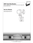
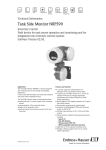
System components
The Tankvision system is physically divided into separate units. Each unit is responsible for
a specific operation. All Tankvision units are connected together through an Ethernet link.
The architecture for the Tankvision system is shown in the figure as follows:
NXA821
Data Concentrator
NXA822
Host Link
Host Computer
NXA820
Tank Scanner
(with inventory
calculations)
L00-NXA820xx-14-00-00-en-002
10
Unit
Description
NXA820
Tank Scanner
•
•
•
•
•
•
NXA821
Data Concentrator
• Provides a single entrance point to Tankvision systems with several NXA820 units.
• Enables grouping of tanks regardless to which NXA820 unit they are connected.
NXA822
Host Link
• Provides a Modbus link (serial Modbus or Modbus TCP/IP) to a DCS host or an Entis+
link to an Entis system.
• Enables Modbus compliant DCS software to monitor and control the tank farm
operation.
Captures measured data from the gauges installed on tanks.
Provides measured data to other Tankvision units and visualization to end users.
Provides the real-time trend of the measured data.
Includes inventory calculations.
Stores measured and calculated inventory data for a certain amount of time.
Generates inventory reports and historical trends.
Endress+Hauser
Tankvision
Getting Started
3.2
The Tankvision User Interface
Tankvision provides an intuitive user interface allowing the user to quickly navigate through
the system. The following sections illustrate various parts of the Tankvision user interface
and their usage.
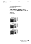
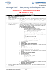
The Home Page
1
3
2
6
4
5
Pos.
Field
Description
1
System Header
Displays the Customer Logo or Graphic.
2
Navigation Tree
Contains header bars corresponding to different functional objects or groups in
the system.
Refer to "Navigation Tree - detailed description" (→ ä 12) for details.
3
Main Header
Displays the following information:
• The site name, tank name, Tankvision tag name or product name depending on what is displayed in the Main View below the header
• The system date and time
The main header is displayed with a background color depending on the access
rights of the user logged into the system:
• Grey: the user does not have configuration rights and can only view non-real
time data.
• Orange: the user has configuration rights and can view real time data.
Endress+Hauser
4
Metadata Header
Displays the following information:
• The user name and the user type
• The language options link
• The help link
• The logout option
5
Main View
Displays the screens that the user has selected to configure the settings and
view the operational information.
Refer to "Main View Section- Colors in Edit Data" (→ ä 12) for details.
6
Alarm and Event
Panel
The Alarm and Event Panel displays the real time information about alarms and
events.
Refer to "Alarm and Event Panel Section- Description" (→ ä 13) for details.
11
Getting Started
Tankvision
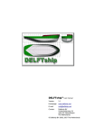
Navigation Tree - Detailed Description
The Navigation Tree is shown on the left side of the screen. Typically, the Navigation Tree
allows the user to navigate down to the tanks. The image of the expanded Navigation Tree
is as follows:
1
2
3
4
Pos.
Field
Description
1
Header
The user can click on the text or the arrow of the Header to expand or collapse
the branch.
The Header name shows a number, which is dynamically appended. The
number states the following:
• Tanks: The number of tanks in the NXA820
• Products: The number of products defined in the system
• Customized Groups: The number of tank groups defined in the system
• Transfers: The number of product transfer stages (Waiting, In Progress,
Finished, and Aborted) defined in the system
• Users: The number of users defined in the system
The text will appear in bold and black when the header is in the expanded form.
2
Collapsed Arrow
This type of arrow is displayed when the Header is in the collapsed position.
Click on the collapsed arrow to expand the Header.
3
Expanded Arrow
This type of arrow is displayed when the Header is in the expanded position.
Click on the expanded arrow to collapse the Header.
4
Node
The user can click on the Node to view the operational information on the Main
View section. If a Node is selected, it will appear in red color.
The number of tanks in the group is appended to the Node name.
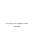
Main View Section - Colors in the Edit Data Area
The system displays different colors in the Edit Data area, based on the access rights of the
user:
1.
If the user has access rights, then the edit data area has a light grey and light yellow
background on alternate rows. The Submit button to save the settings is enabled.
NXA82x_Tank-Capacity-Table-Summary
12
Endress+Hauser
Tankvision
Getting Started
2.
If the user does not have access rights, then the edit data area has a light grey and dark
grey background on alternate rows. The Submit button to save the settings is disabled.
NXA82x_Tank-Capacity-Table-Summary_Inactive
Alarm and Event Panel - Description
The Alarm and Event Panel displays the alarm and event information, which is dynamically
generated by the system.
Endress+Hauser
Tab
Description
Alarm
Displays details of the alarms generated by the system.
Events
Displays details of the events generated by the system.
Alarm & Events
Displays details of the alarms and events generated by the system.
13
Getting Started
Tankvision
3.3
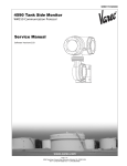
Logging into the Tankvision system
To integrate a Tankvision unit (i.e. a Tank Scanner NXA820, Data Concentrator NXA821 or
Host Link NXA822) into the network, proceed as follows:
1. Connect a laptop to the service port of the Tankvision unit. Make sure that the laptop is
3
3
2
2
POWER
E
L-
1
1
10,5 ... 32V DC
configured to get a dynamic IP addresses from a DHCP server.
L+
RESET
Fuse
13
12
10
11
RESET
10 11 12 13
2AT
6
6
7
7
MODBUS
8
8
W &M
Alarm Relay
L00-NXA82xxx-04-00-00-yy-025
2. Open the internet browser and enter the following URL: http://192.168.1.1
The Tankvision login screen appears. You are logged in as Operator 1).
3. Login as Supervisor.
Click on Login in the Meta header, the following screen opens:
NXA82x_Login-Screen
Field
Description
User ID
Enter the appropriate user login name 1). The user login name is alphanumeric and case
sensitive.
Password
Enter the appropriate password.1)
The user password is alphanumeric and case sensitive. It consists of 3 to 8 characters.
1)
1)
14
The user ID ( = User Login Name) and password are defined by the system administrator when adding a
user to the system.
Description of Functions: Operators do not have the right to change settings. Supervisors are permitted to change settings.
Endress+Hauser
Tankvision
Getting Started
Enter ...
• ... "Super" into User ID.
• ... "Super" into Password.
• Click the Login button.
Tankvision displays the Home Page as follows:
NXA82x_Home-Screen
3.4
Common settings - Tankvision system
stand alone /
subscription store
all other units
Network configuration
subscription store settings
units
customer additional settings
environment settings
Products
Users and users rights
global configuration store
device specific settings
L00-NXA82xxx-16-00-00-en-001
Endress+Hauser
15
Getting Started
Tankvision
3.4.1
Network settings
You are logged in as "Supervisor".
1. In the navigation tree, click the System Header. It expands as follows:
NXA82x_Menu_System
2. Click Global Settings. Tankvision displays the screen as follows:
NXA82x_System-Screen
3. Click
on Network Settings. Tankvision displays the screen as follows:
NXA82x_Network-Settings
4. Enter the appropriate information in the relevant fields.
16
Endress+Hauser
Tankvision
Getting Started
Observe the following when entering information into the fields:
• Parameters marked by an asterisk are mandatory.
• The required values of the parameters depend on your local network configuration. For
more information please contact your local network administrator.
• Detailed information on the individual fields, → ä 128.
5. Click the Submit button to proceed. The system displays a confirmation box as follows:
6. Click the OK button to proceed, or click the Cancel button to exit.
7. After saving the settings, Tankvision displays a confirmation message.
8. Disconnect the laptop and connect the Tankvision unit to the network using the System
LAN port. The Tankvision unit can now be operated from a computer within the LAN.
Endress+Hauser
17
Getting Started
Tankvision
3.4.2
Network Node Detection
The Network Node Detection helps to detect and connect to all devices in the same network.
This is a precondition for a global/local scenario (e.g.to use a Data Concentrator NXA821 as
a Global Store or for the usage of Subscription Stores).
To do so, proceed as follows:
1. Login to the Tankvision unit as "Supervisor" and navigate to the Global Settings screen
as described in "Network settings", → ä 16.
Click on Customer Settings.
2. Click
on Network Node Detection. Tankvision displays the screen as follows:
NXA82x_Network-Settings_Network-Node-Detection
Field
Description
Scan Method
Select the appropriate Scan Method from this field. Choose between scanning for a single
IP address (Scan Address) and scanning a range of IP addresses (Scan Address Range).
Timeout in
Milliseconds
Enter the appropriate scan timeout (in milliseconds) in the text box.
Enter Address
Enter the known IP address of a device in the network into the text boxes.
This field is only available when Scan Address was selected for Scan Method.
Enter Address Range
Enter a range of IP addresses, that are in the same network as the current device, into the
text boxes.
This filed is only available when Scan Address Range was selected for Scan Method.
Message
Displays a message after the scan, e.g. how many devices were detected.
Detected Units
Lists all the devices that were detected during a scann.
Connected Units
Lists all devices that are already connected to the current device.
Distrubute
Connected Units
Select the check box to distribute the selected Detected Units to all connected units when
clicking Save Connected Units.
Clear the check box to save the selected Detected Units only to the current device when
clicking Save Connected Units.
3. Enter the appropriate information in the relevant fields.
18
Endress+Hauser
Tankvision
Getting Started
4. Click Perform Scan to start the Network Node Detection.
During the scan a progress bar is displayed. The rest of the screen is locked while the
progress bar is displayed.
5. Click on the detected units (multiple selection by holding the Ctrl key while clicking) to
select the detected units that are to be saved. Click Save Connected Units to save the
selected units (and the current device).
Click Clear Detected Units to clear the Detected Units.
If a device in the network is removed or replaced, repeat the Network Node Detection
to update the connected devices.
3.4.3
Monitoring Configuration
Configure the interval and timeout for monitoring the other devices in the network as well
as the network quality.
To do so, proceed as follows:
1. Login to the Tankvision unit as "Supervisor" and navigate to the Global Settings screen
as described in "Network settings", → ä 16. Click
2. Click
on Customer Settings.
on Monitoring Configuration. Tankvision displays the screen as follows:
NXA82x_Network-Settings_Monitoring-Configuration
Column
Description
Unit Type
Displays the device type (Tank Scanner NXA820, Data Concentrator NXA821, Host Link
NXA822).
Monitoring interval
in Milliseconds
Enter the appropriate interval, in which the current device checks if the other devices in
the network are available, in the text box.
Timeout in
Milliseconds
Enter the appropriate timeout for the availability check of the other devices in the
network in the text box.
Field
Description
QNet-Timeout & Retry Setings
Select the appropriate network quality. The names of the settings are self-explanatory.
3. Enter the appropriate information in the relevant fields.
4. Click the Save Monitoring Configuration button.
3.4.4
Time Server Settings
The availability of the Time Server Settings depends on the Configuration Store Type
selected in Define Configuration Store Details (→ ä 21).
Synchronize the time of the device with a time server in the network.
To do so, proceed as follows:
Endress+Hauser
19
Getting Started
Tankvision
1. Login to the Tankvision unit as "Supervisor" and navigate to the Global Settings screen
as described in "Network settings", → ä 16. Click
2. Click
on Customer Settings.
on Time Server Settings (NTP). Tankvision displays the screen as follows:
NXA82x_Network-Settings_Time-Server-Settings
Field
Description
Synchronize time
against time server
Select the check box to synchronize the system time of the current device with a time
server in the network.
Clear the check box to use the system time of the current device.
Only available if Subscription Store is selected as the Configuration Store Type in
Define Configuration Store Details (→ ä 21).
Not available if Use Local Configuration Store is selected as the Configuration Store
Type, because this setting always uses the system time of the current device.
If Use Global Configuration Store is selected as the Configuration Store Type, the IP
address of the configured Subscription Store is automatically used as time server.
Server IP-Address
Enter the appropriate IP address of a time server. The IP address has to be available in the
network of the current device.
Entering the IP address "127.127.1.0" (default) synchronizes with the internal real-time
clock of the current device.
If an invalid IP address is entered and Submit button is clicked, the field returns to the
last valid IP address.
This field is only available if the Synchronize time against time server check box is
available and selected.
NOTE! Do not use other Tankvision devices as time servers.
3. Enter the appropriate information in the relevant fields.
4. Click the Submit button.
The time of synchronization depends, amongst other things, on the network quality.
20
Endress+Hauser
Tankvision
Getting Started
3.4.5
Subscription Store definition
In a typical Tankvision system, most configuration settings are common for all Tankvision
units within the network. Therefore, the time required for the configuration of the system
can be minimized by defining one of the units to be a Subscription Store. The configuration
settings are only performed on this Subscription Store. These settings are then distributed to
the other units within the network.
For each Tankvision unit (i.e. Tank Scanner NXA820, Data Concentrator NXA821 or Host
Link NXA822) within the network it is necessary to define if it is a Subscription Store or if it
receives its configuration from a Subscription Store.
To do so, proceed as follows:
1. Login to the Tankvision unit as "Supervisor" and navigate to the Global Settings screen
as described in "Network settings", → ä 16. Click
on Customer Settings.
2. Click
on Define Configuration Store Details. Tankvision displays the screen as
follows:
NXA82x_Define-Configuration-Store-Details
3. For the Subscription Store:
• In Configuration Store Type select the option Subscription Store (Default)
For the other units
• In Configuration Store Type select the option Use Global Configuration Store
• In Subscription Store select the Subscription Store to which this unit is to be linked
• In Allow Local Configuration Change define whether local configuration changes of this
unit are allowed in case the Subscription Store is not available.
4. Click the Submit button to proceed, or click the Refresh button to reset the screen.
5. After saving the settings, Tankvision displays a confirmation message.
With the (recommended) use of global configuration store the following information is
transferred to the subscription units:
• Customer settings like site information (without customer specific logo), unit, email server
and day and time settings (configurations of languages and printer agent must be done for
every single device)
• Environment settings
• Products
• Users incl. user access rights
Global settings could be changed later on, also after assigning other units. It is highly
recommended to use a NXA820 as subscription store.
Endress+Hauser
21
Getting Started
Tankvision
3.4.6
Further common steps (stand alone or subscription store)
Login to the Tank Scanner NXA820 as "Supervisor" and perform the following
configurations:
1.
Customer Settings and Environment Settings
a. In the navigation tree, click the System header.
b. Click Global Settings (below the System header).
c. In the main screen click the Customer Settings header and configure the
parameters (→ ä 199).
d. In the main screen, click the Environment Settings header and configure the
parameters (→ ä 199).
2.
Product Configuration
a. In the navigation tree, click the Products header.
b. Click the Add button to add a new product.
c. Click the individual headers of the Product menu (General Details, Volume
Correction Factor, ...) and define the product properties (→ ä 91).
3.
Users and user access rights
a. In the navigation tree, click the Users header.
b. Click on Group rights tab and define the rights of the different users.
c. Click on User view and create the required users.
22
Endress+Hauser
Tankvision
Getting Started
3.4.7
Tank Scanner NXA820 specific settings
Login to the Tank Scanner NXA820 as "Supervisor" and perform the following
configurations:
1.
Field Scan Configuration
a. In the navigation tree, click the System header.
b. Click Global Settings (below the System header).
c. In the main screen, click the Field Scan header.
d. Click the individual headers of the Field Scan menu and configure the parameters 2).
For a description of the parameters refer to
– Chap. 12.5 (Modbus)
– Chap. 12.6 (V1)
– Chap. 12.7 (WM550)
2.
Tank Configuration
a. In the navigation tree, click the Tanks header.
b. In the main screen, select the tank you are going to configure and click the Modify
button.
c. Click the individual headers of the tanks menu (General Details, Capacity Details,
...) and configure the parameters (→ ä 35).
3.
Product-tank assignment
a. In the navigation tree, click the Tanks header.
b. In the list below the Tanks header select a tank.
c. In the main screen click the Assignment Product tab (if necessary use the << or >>
button to find the Assign Product tab.
d. Select the product from the drop-down list.
e. Click Submit to save the settings.
For details about tank-product assignment refer to Chap. 8.7.
4.
Additional Settings
Depending on your requirements, you can perform numerous further settings.
5.
Start Field Scan
a. In the navigation tree, click the System header.
b. Click Global Settings (below the System header).
c. In the main screen, click the Field Scan header.
d. Click the Start/Stop Field Scan tab and then click on Start. Field Scanning is now
active.
2)
The parameters can only be edited if the field scan is not currently active. If necessary, go to the Start/Stop Field Scan tab and stop the field scan.
Endress+Hauser
23
Getting Started
Tankvision
3.4.8
1.
Data Concentrator NXA821 specific settings
Associate Tank Scanner
Assign the Tank Scanner NXA820 to the Data Concentrator NXA821:
a. Login to the Data Concentrator NXA821 as "Supervisor".
b. In the navigation tree, click the System header.
c. Click Global Settings (below the System header).
d. In the main screen, click the header Tank Scanner Unit And Tank Assignment.
e. Select all Tank Scanner units you want to assign to the Data Concentrator from the
Available Units list and move them to the Selected Units list using the arrow
buttons. All units in the Selected Units list will be assigned to the Data
Concentrator.
f. Click the Submit button to save the settings.
2.
Additional Settings (like groups)
Depending on your requirements, you can perform numerous further settings.
3.4.9
Host Link NXA822 specific settings
The Host Link NXA822 provides an interface for a host system to access inventory data from
the NXA820 unit. To configure the Host Link settings, proceed as follows:
24
1.
Login to the Host Link NXA822 as "Supervisor".
2.
In the navigation tree, click the System header.
3.
Click Global Settings (below the System header).
4.
In the main screen, click the Field Scan header.
It contains the following sub-headers which are used to configure the Host Link settings
and to start the Host Link:
– Host Link Configuration
– Modbus TCP Configuration (if the Modbus TCP protocol has been selected).
– Modbus Serial (if the Modbus Serial protocol has been selected).
– Entis+ (if the Entis+ serial protocol has been selected)
– Start/Stop Host Link
Endress+Hauser
Tankvision
Getting Started
3.4.10
Configuration of W+M systems
Description of the sealing process
Locking mechanisms in Tankvision:
Connected PCs are registered in the system by assigning the MAC address. Once the system
has been locked, only these PCs are accepted and can display calibrated data.
When the W+M switch is flipped, a checksum is calculated and set.
This calculation is repeated every 8 hours. If this checksum deviates from that at the time of
sealing, changes have been made to the system. It is no longer possible to modify W+M
parameters, such as tank tables, units and print templates, once the W+M switch has been
flipped.
Recommended procedure:
It is recommended to start calibrating the tank gauging system from the field devices via
possible protocol converters and finish the process with the Tankvision inventory
management system. When calibrating the Tankvision Tank Scanner or Data Concentrator,
it is recommended to start with the unit used as the Global Configuration Store since the
engineering units are configured centrally here. These units would then not have to be
checked separately in the boxes assigned (see "Units", → ä 26).
Endress+Hauser
25
Getting Started
Tankvision
Initial calibration and system modifications
Initial calibration and changes to the Tankvision Tank Scanner NXA820
Units
The units do not have to be configured if Use Global Configuration Store (→ ä 21) is
selected. The units can be checked under System → Tank Scanner Unit → Customer
Settings → Units.
This view allows the user to choose between the unit schemes.
Selecting the Unit
The exact settings of the unit scheme selected can be checked under Advanced.
NXA82x_Units
Checking the Units
Observe the following information!
• An apostrophe may not be chosen as the thousand separator for W&M applications.
• If the Tankvision device retrieves the basic settings from another Tankvision device (Global
Configuration Store), the units of this Tankvision device do not have to be checked. The
name of the box (Subscription Store) that provides the basic settings can be found under
System → Global Settings → Customer Settings → Define Configuration Store Details
(Fig. Configuration Store Details).
NXA82x_Define-Configuration-Store-Details
Configuration Store Details
26
Endress+Hauser
Tankvision
Getting Started
Field device assignment
The field device assignment must be checked under System → Tank Scanner Unit → Field
Scan → Manage Field Scan Configuration-Modbus EIA485.
The following parameters have to be checked for Modbus EIA485:
• Baud rate
• Parity
• Gauge slave address: assignment to the tank ID / tank name
• Gauge type: assignment to the tank ID / tank name
• Modbus register map: assignment to the field device type (gauge type)
Field Scan Configuration - Modbus
Endress+Hauser
27
Getting Started
Tankvision
The following parameters have to be checked for the V1 protocol:
• Gauge slave address (DEC) assignment to the tank ID / tank name
• Gauge type assignment to the tank ID / tank name
• V1 map file assignment to the gauge type
Field Scan Configuration - V1 Protocol
The following parameters have to be checked for the WM550 protocol:
• Baud rate
• Loop current
• Gauge slave address assignment to the tank ID / tank name
• Gauge type assignment to the tank ID / tank name
• WM550 map file assignment to the field device type (gauge type)
28
Endress+Hauser
Tankvision
Getting Started
Field Scan Configuration - WM550 Protocol
Endress+Hauser
29
Getting Started
Tankvision
Tank table
The tank capacity details have to be loaded to check the tank table (Tanks → Select the tank
under Select - select and confirm with Modify (see Fig. "Tank Selection") → Select Capacity
Details (see Fig. "Tank Capacity Table Summary")).
Tank Selection
NXA82x_Capacity-Details
Tank Capacity Table Summary
Steps for checking the tank table:
• Check that the information in the Tank Capacity Table Summary is correct for the selected
tank.
• Check whether the TCT is suitable for the relevant tank.
Clicking Show TCT file opens a browser window that shows the TCT in a tabular form
(with the units in the configured format). Print by clicking Print TCT.
To store the TCT file on a PC, click the Get TCT file link. The system will perform an export
of the TCT in XML form as a compressed file (.gz). All units in the file are SI units
(independent from the configured format).
30
Endress+Hauser
Tankvision
Getting Started
Tankvision_TCT
Table in XML Format
Endress+Hauser
31
Getting Started
Tankvision
PC assignment
Tankvision Tank Scanner - PC Assignment
Every PC to be connected to the sealed system has to be registered. The PCs are registered
under System → Global Settings → W&M Seal → Access Configuration.
The registered devices are listed with their MAC address in the column on the left.
The MAC address of the PC currently used is displayed in the column on the right.
Each PC has to be registered individually on every Tankvision box. If no PC is registered in
the system, an error message is shown on the display of the Tankvision box once the W+M
switch has been flipped.
NXA
0.0.0.0
172.0.0.1
02/12/2009
02:51:54 PM
NXA820_A30016011
F317:
Access Configuration Er
INFO
L00-NXA820xx-07-00-00-xx-001
Error Message - No PC Registered in the System
During calibration acceptance, the list must be checked to ensure it only contains the MAC
addresses of the Tankvision boxes and the PCs that should access the system. The PCs can
be checked, for example, by loading the page above from every PC that should have access
to the system and then comparing the MAC addresses (Registered Systems against Current
MAC Address). The MAC addresses of the Tankvision box are provided on the nameplate.
32
Endress+Hauser
Tankvision
Getting Started
Sealing tank data
The tank data are sealed individually for every tank. The W+M values are selected under :
Tanks → Select the Tank (Select + Modify) → Put Tank into Calibrated Status.
For more details, → ä 54.
NXA82x_Put-Tank-into-Calibrated-status
Sealing Tank Data
If the W+M switch is flipped, tanks can be removed from the calibrated status. This
changes the calibration checksum. Removing a tank from the sealed system is
equivalent to a system modification and must be accepted by an official from the
Standards Authority.
Locking
3
2
3
E
L-
1
POWER
2
1
10,5 ... 32V DC
The unit is locked by flipping the W+M switch on the Tankvision Tank Scanner NXA820.
L+
RESET
Fuse
10 11 12 13
10
11
RESET
12
13
2AT
6
6
7
7
MODBUS
8
8
W &M
NXA Status
Relay
A
L00-NXA82xxx-04-00-00-xx-002
A
Tankvision W+M Switch
Flipping the switch means that the settings checked under "Sealing tank data" (→ ä 33) are
fixed and can no longer be modified, and that the values specified under Sealing Tank Data
are displayed as calibrated values by the computers specified under PC Assignment. A
master checksum is calculated approx. 2 minutes after the W+M switch is flipped. This
master checksum can be called up under System → Tank Scanner Unit → W&M Seal. After
approximately 2 more minutes, the system performs the first check calculation. The
subsequent calculations are then performed every 8 hours.
The following information is displayed:
• Date and time the page was loaded
• W&M switch status
• W&M CRC at sealing time
• Last calculated W&M CRC
• Last calculated CRC’s time stamp
Tankvision W&M Seal
Endress+Hauser
33
Getting Started
Tankvision
A modified checksum indicates that changes have been made to the system. The checksum
must be documented (e.g. by printing out the screenshot, see Figure "Tankvision W&M Seal")
and recorded in the acceptance report (e.g. by attaching the printout).
The checksum can be recalculated by switching the Field Scan off and then on again.
Checking the W&M display
The following steps must be taken to check the weights and measures display:
• The settings listed under "Sealing tank data" (→ ä 33) can no longer be modified.
• A WM in front of the values for the Product Level, Product Temperature and Total
Observed Volume indicates that the values are calibrated.
• The level and temperature information has to match that of the field devices.
Checking the printouts
All printouts from connected printers that cannot be officially verified must bear the
annotation "Measured values not calibrated" and no measured values may appear as
calibrated.
Initial calibration and changes to the Tankvision Data Concentrator NXA821
Tank Scanner assignment
The assignment between the Tank Scanner units and the Data Concentrator must be
checked under System → Data Concentrator Unit → Tank Scanner Unit and Tank
Assignment.
Tankvision Data Concentrator - Tank Scanner Assignment
PC assignment
The locking procedure is the same as for the tank scanner (see "Locking", → ä 33).
Stamp points for Tankvision Tank Scanner NXA820 and Data Concentrator NXA821
The stamp points are listed under Point 6 in type approval 4.454/08.10.
34
Endress+Hauser
Tankvision
The Tankvision Operating Screens
4
The Tankvision Operating Screens
Operating Screen
NXA820
NXA821
x
x
→ ä 37
General Details
x
x
→ ä 38
Capacity Details
x
x
→ ä 40
Shell Details
x
x
→ ä 45
Floating Roof
x
x
→ ä 47
Flow Calculation
x
x
→ ä 49
Water Content
x
x
→ ä 51
Hybrid Tank Measurement System
x
x
→ ä 52
Inventory Calculation
x
x
→ ä 53
Put Tank into Calibrated Status
x
x
→ ä 54
HART command
x
x
→ ä 55
x
x
→ ä 56
Measured Data Alarm Configuration
x
x
→ ä 57
Calculated Data Alarm Configuration
x
x
→ ä 59
Tanks - Gauge Commands Tab
x
x
→ ä 61
Tank Screen
x
x
→ ä 63
The "General Details" tab
x
x
→ ä 64
The "Spot Temperature" tab
x
x
→ ä 66
The "Manual Data" tab
x
x
→ ä 67
The "Dipped Data" tab
x
x
→ ä 68
The "Gauge Commands" tab
x
x
→ ä 69
The "Real Time Trend" tab
x
x
→ ä 73
The "Product Transfer" tab
x
x
→ ä 75
Tanks - Tank Details Tab
Tanks - Alarm Settings Tab
Page
The "Tank Status" tab
x
x
→ ä 84
The "Assign Product" tab
x
x
→ ä 87
The "Product Transfer Report" tab
x
x
→ ä 88
The "Tank Calculator" tab
x
x
→ ä 88
x
x
→ ä 91
Adding, Modifying and Deleting Products
x
x
→ ä 91
General
x
x
→ ä 93
Volume Correction Factor (VCF)
x
x
→ ä 94
Reference Density Calculation (RDC)
x
x
→ ä 95
Sediment & Water
x
x
→ ä 96
Mass & Weight
x
x
→ ä 98
Vapor Calculation
x
x
→ ä 99
Advanced (Weight & Measure)
x
x
→ ä 100
View Product Tank Groups
x
x
→ ä 101
Menu Customized Groups
x
x
→ ä 105
Menu Transfers
x
x
→ ä 114
Menu Products
Endress+Hauser
NXA822
35
The Tankvision Operating Screens
Tankvision
Operating Screen
NXA820
NXA821
NXA822
Page
x
x
x
→ ä 116
Customer Settings
x
x
x
→ ä 117
Network Setting
x
x
x
→ ä 128
Environment Settings
x
x
x
→ ä 134
Trend Global Settings
x
x
x
→ ä 135
Field Scan - Modbus EIA485
x
Configure Field Scan - Sakura V1
x
Configure Field Scan - Whessoe WM550
x
W&M Seal
x
x
Data Archival
x
x
→ ä 153
x
→ ä 160
Menu System
Tank Scanner Unit and Tank Assignment
→ ä 136
x
→ ä 141
→ ä 146
Host Link
x
→ ä 151
x
→ ä 161
Downloads
x
x
x
→ ä 181
Operator Workstation Settings
x
x
x
→ ä 185
System Diagnostics
x
x
x
→ ä 187
Uploads
x
x
x
→ ä 189
Tankvision Outputs
x
x
x
→ ä 197
x
x
x
→ ä 198
Select NXA820 Configuration Details
x
x
x
→ ä 199
Select Product Transfer Details
x
Event Report
x
x
Alarm Report
x
x
→ ä 200
Select Tanks For Tank Report
x
x
→ ä 201
Select Tanks For Tank Detail Report
x
x
→ ä 201
Select Tank Groups For Report
x
x
→ ä 202
Select Inventory Report
x
x
→ ä 202
Menu Users
x
x
KPI Dashboards
x
Menu Reports
36
x
→ ä 199
x
x
→ ä 200
→ ä 203
→ ä 211
Endress+Hauser
Tankvision
The "Tanks" menu - Tank Details
5
The "Tanks" menu - Tank Details
The working of the entire Tankvision system depends on the tanks and their contents. The
Tankvision system acquires measured data from the gauges, processes these data using
Tank Inventory calculations and then presents the data on the Tankvision interface for the
user to view or access. Some of the inventory data such as volume and mass depend on the
tank configuration and the product assigned to the tank.
To configure a tank
1. On the Navigation Tree, click the Tanks Header. (The number of tanks configured is
displayed in brackets next to the Header’s name). The Manage Tanks screen appears:
2. Select the appropriate tank by clicking on the selection box in front of the tank.
3. Click the Modify button to modify the tank details. Tankvision displays the Tank
Details screen as follows:
With the Manage Tanks button, you can step back to the Manage Tanks screen.
Endress+Hauser
37
The "Tanks" menu - Tank Details
5.1
Tankvision
General Details
The General Details screen allows the user to view and modify the general details of the tank
according to the requirements.
To configure the general details of the tank
1. Click
on General Details. Tankvision displays the screen as follows:
NXA82x_Tank-Details_General-Details
Field
Description
Tank ID
Each tank in the system has a unique numerical identifier ranging from 1 to 15. This ID is
used in the system to refer to the tank to display the tank data, perform product transfer,
generate reports, etc. This field is not editable.
Tank Name
Enter the name of the tank. Each tank in the Tankvision system has a unique name for
reference, which should not exceed 16 characters in length. The data type for this field is
alphanumeric and can contain the special characters "-" and "_" (hyphen and underscore).
Tank Location
Enter the location of the Tank. This field is used to identify the tank and enables the
creation of a tank group based on the physical location of the tank in a tank farm.
The data type for this field is alphanumeric and can contain all special characters.
Tank Level Type
Select the appropriate settings in which way the measured value is transmitted from
gauge. Innage or Ullage.
Tank Type
Select the appropriate type of tank from the drop down list.
This field indicates whether the tank has a floating roof or not. This enables the
Tankvision system to decide whether to perform the floating roof adjustment during
tank calculation.
Gauge Model
Enter the appropriate gauge model name or number for the tank.
The data type for this field is alphanumeric and can contain all special characters.
Gauge Reference
Height
Enter the appropriate height of the gauge or tank top. The field is used to convert the
product ullage level to the innage level. The data type for this field is numeric.
Pressure Transmitter Enter the appropriate pressure type option. This field specifies, whether the measured
Type
pressure is absolute or relative if the pressure is measured using a pressure gauge.
Position of Lowest
Temperature Sensor
Enter the value of the position of the lowest temperature sensor.
This field indicates the level of the lowest temperature sensor. If the product level falls
below the position of lowest temperature sensor, then the temperature measured by this
sensor can no more be considered as product temperature in the tank calculations.
Temperature Status
When Level is too
Low
Select the appropriate temperature status from the drop down list.
This field indicates the temperature status when the product level drops below the
position of the lowest temperature sensor. This enables the system to change the value of
the temperature status to an existing value in the drop down list.
Change Picture
Click the Change Picture link to change the picture of the tank.
Refer to section "Change Tank Picture" (→ ä 39) for more details.
2. Enter the appropriate information in the relevant fields.
3. Click the Submit button to save the tank general details.
38
Endress+Hauser
Tankvision
The "Tanks" menu - Tank Details
4. After saving the settings, Tankvision displays a confirmation message.
An event is generated after configuring the tank general details. The event details can
be viewed in the Event or Alarm & Event overview.
5.1.1
Change Tank Picture
To change the tank picture
1. Click the Change picture link on the General Details screen. Tankvision displays the
screen as follows:
NXA82x_Tank-Details_Change-Tank-Picture
2. Click the appropriate option to select the picture.
3. Click the Submit button to save the tank image or click the Cancel button to exit.
4. Tankvision returns to the General Details screen.
Endress+Hauser
39
The "Tanks" menu - Tank Details
5.2
Tankvision
Capacity Details
Capacity Details are used to calculate the product volume from the product level. The most
common industry method to measure the product volume is to use a Tank Capacity Table
(TCT).
A TCT has a number of data points for each level in the tank and it gives the product volume
corresponding to these levels. The Capacity Details screen allows you to view and modify
the details of the tank in terms of the tank capacity table, total volume, minimum volume of
the product that can be pumped out of the tank, etc.
To configure tank capacity details
1. Click
on Capacity Details. Tankvision displays the screen as follows:
NXA82x_Capacity-Details
Field
Description
Select TCT file to Download Enter the appropriate path to download the TCT file, or click the Browse button to
search for an appropriate file location. The system reads the product level and uses
the corresponding volume from the TCT as the product volume for further
calculations. Read more about the TCT file contents below.
Sump & Pipeline Volume
Enter the value of the sump and pipeline volume. This field indicates the volume of
the product contained in the sump and pipeline. The data type for this field is
numeric.
Maximum Tank Capacity
Indicates the maximum volume which can be filled into a tank.
Volume Calculation
Method
Value: Raw
Sub Table Present
Indicates wether a sub strapping table is present in the downloaded Tank Capacity
Table.
Product Density for FRA
P_Density_FRA, if present is the density used to calculate the displaced volume.
Heel Volume
"Waste" volume, located on the tank bottom, it’ll be substracted from the actual
volume.
TCT Level Type
Defines the level type of entered straps in the Tank Capacity Table.
Values: Innage, Ullage
Minimum pumpable
volume
Indicates the minimum pumpable volume of the attached pump on the tank.
While configuring a product transfer this should be considered as minimum batch
size.
Number of Straps
Value shows the number of straps read from the Tank Capacity Table.
Water Table Present
Indicates whether a water table is present in the downloaded Tank Capacity Table.
Volumetric Floating Roof
Correction
V_FRC, if present it is used to correct the volume.
Get TCT file
Link to download a Tank Capacity Table.
Static Pressure Table
Present
Indicates whether a table for static pressure correction is present in the
downloaded Tank Capacity Table.
View TCT file
Link to view a Tank Capacity Table.
2. Click the Browse button to search the TCT file location.
40
Endress+Hauser
Tankvision
The "Tanks" menu - Tank Details
3. Click the Download Tct Xml File button to download a TCT XML file from the system.
4. Enter the sump and pipeline volume in the Sump & Pipeline Volume field.
5. Click the Submit button to save the tank capacity details.
6. Tankvision displays the capacity details in the Tank Capacity Table Summary section,
which is imported from the TCT file. After saving the details, Tankvision also displays a
confirmation message.
An event is generated after configuring the tank capacity details. The event details can
be viewed in the Event or Alarm & Event overview.
Endress+Hauser
41
The "Tanks" menu - Tank Details
5.2.1
Tankvision
TCT XML file contents
The TCT file is a XML file, which provides the following information about the tank.
42
XML Tag
Definition
TCT_Date
TCT Date
TCT_CalDate
TCT Calibrated Date
Level_Type
Level Type
Volume_Method
Volume Method
Units
Level
Units
- Level Unit
Volume
- Volume Unit
Weight
- Weight Unit
P_Density_FRA
- Density Unit
FRA_TCT
P_Density_FRA
Floating Roof Details
- Used Liquid Density
V_FRC
- Volumetric FR Correction
Heel_Volume
Heel Volume
Max_Tank_Capacity
Max Tank Capacity
Total_Tank_Volume
Total Tank Volume
Min_Pump_Volume
Minimum Pumpable Volume
P_TCT
CNT
Main TCT Table
- Number of TCT straps
P_Strap
- - Each Strap
P_Level
- - - Level
P_Volume
- - - Volume
Sub_TCT
Sub TCT Present
Min_Sub_TCT_Level
Minimum Sub TCT level
P_S_TCT
CNT
Sub TCT Table
- Number of Sub TCT Straps
P_S_Strap
- - Each Strap
P_S_Level
- - - Level
P_S_Volume
- - - Volume
WATER_TCT
Water Table Present
Water
CNT
Water Table
- Number of Water TCT Straps
W_Strap
- - Each Strap
W_Level
- - - Level
W_Volume
- - - Volume
VSP_TABLE
Static Pressure Table Present
VSP_TABLE
CNT
Static Pressure Table
- Number of VSP straps
P_Strap
- - Each Strap
P_Level
- - - Level
VSP_Vol
- - - Volume
Endress+Hauser
Tankvision
The "Tanks" menu - Tank Details
Sample TCT file
<?xml version =“1.0"?>
<?xml-stylesheet type =“text/xsl“ href= “nxa820tct.xsl“?>
<Tankvision CRC =“12345“>
<TCT TCT_Date=“3/28/2011“ TCT_CalDate=“3/28/2011“ Sub_TCT=“N“ WATER_TCT=“W_TCT“ VSP_TABLE=“Y“>
<Level_Type>Innage</Level_Type>
<Units>
<Level>mm</Level>
<Volume>m3</Volume>
<P_Density_FRA_Unit>kg/m3</P_Density_FRA_Unit>
</Units>
<FRA_TCT>
<P_Density_FRA>1500</P_Density_FRA>
<V_FRC>1</V_FRC>
</FRA_TCT>
<Heel_Volume>50</Heel_Volume>
<Total_Tank_Volume>62369</Total_Tank_Volume>
<Max_Tank_Capacity>61745</Max_Tank_Capacity>
<Min_Pump_Volume>624</Min_Pump_Volume>
<Volume_Method>RAW</Volume_Method>
<P_TCT CNT=“13">
<P_Strap><P_Level>0</P_Level><P_Vol>87</P_Vol></P_Strap>
<P_Strap><P_Level>50</P_Level><P_Vol>500</P_Vol></P_Strap>
<P_Strap><P_Level>100</P_Level><P_Vol>1000</P_Vol></P_Strap>
<P_Strap><P_Level>200</P_Level><P_Vol>2000</P_Vol></P_Strap>
<P_Strap><P_Level>410</P_Level><P_Vol>5771</P_Vol></P_Strap>
<P_Strap><P_Level>470</P_Level><P_Vol>6604</P_Vol></P_Strap>
<P_Strap><P_Level>1000</P_Level><P_Vol>14047</P_Vol></P_Strap>
<P_Strap><P_Level>1080</P_Level><P_Vol>25170</P_Vol></P_Strap>
<P_Strap><P_Level>2440</P_Level><P_Vol>44039</P_Vol></P_Strap>
<P_Strap><P_Level>2580</P_Level><P_Vol>45976</P_Vol></P_Strap>
<P_Strap><P_Level>4160</P_Level><P_Vol>57809</P_Vol></P_Strap>
<P_Strap><P_Level>10000</P_Level><P_Vol>80000</P_Vol></P_Strap>
<P_Strap><P_Level>20000</P_Level><P_Vol>100000</P_Vol></P_Strap>
</P_TCT>
<W_TCT CNT=“10">
<W_Strap><W_Level>-1000</W_Level><W_Vol>0</W_Vol></W_Strap>
<W_Strap><W_Level>-778</W_Level><W_Vol>222.22</W_Vol></W_Strap>
<W_Strap><W_Level>-556</W_Level><W_Vol>444.44</W_Vol></W_Strap>
<W_Strap><W_Level>-333</W_Level><W_Vol>666.66</W_Vol></W_Strap>
<W_Strap><W_Level>-111</W_Level><W_Vol>888.88</W_Vol></W_Strap>
<W_Strap><W_Level>111</W_Level><W_Vol>1111.1</W_Vol></W_Strap>
<W_Strap><W_Level>333</W_Level><W_Vol>1333.32</W_Vol></W_Strap>
<W_Strap><W_Level>555</W_Level><W_Vol>1555.54</W_Vol></W_Strap>
<W_Strap><W_Level>778</W_Level><W_Vol>1777.76</W_Vol></W_Strap>
<W_Strap><W_Level>1000</W_Level><W_Vol>1999.98</W_Vol></W_Strap>
</W_TCT>
<VSP_TABLE CNT=“23">
<P_Strap><P_Level>1000</P_Level><VSP_Vol>0</VSP_Vol></P_Strap>
<P_Strap><P_Level>1100</P_Level><VSP_Vol>0</VSP_Vol></P_Strap>
<P_Strap><P_Level>1200</P_Level><VSP_Vol>0</VSP_Vol></P_Strap>
<P_Strap><P_Level>1300</P_Level><VSP_Vol>0</VSP_Vol></P_Strap>
<P_Strap><P_Level>1400</P_Level><VSP_Vol>13</VSP_Vol></P_Strap>
<P_Strap><P_Level>1500</P_Level><VSP_Vol>14</VSP_Vol></P_Strap>
<P_Strap><P_Level>1600</P_Level><VSP_Vol>16</VSP_Vol></P_Strap>
<P_Strap><P_Level>1700</P_Level><VSP_Vol>22</VSP_Vol></P_Strap>
<P_Strap><P_Level>1800</P_Level><VSP_Vol>28</VSP_Vol></P_Strap>
<P_Strap><P_Level>1900</P_Level><VSP_Vol>34</VSP_Vol></P_Strap>
<P_Strap><P_Level>2000</P_Level><VSP_Vol>40</VSP_Vol></P_Strap>
<P_Strap><P_Level>3000</P_Level><VSP_Vol>102</VSP_Vol></P_Strap>
<P_Strap><P_Level>4000</P_Level><VSP_Vol>215</VSP_Vol></P_Strap>
<P_Strap><P_Level>5000</P_Level><VSP_Vol>360</VSP_Vol></P_Strap>
<P_Strap><P_Level>6000</P_Level><VSP_Vol>542</VSP_Vol></P_Strap>
<P_Strap><P_Level>7000</P_Level><VSP_Vol>789</VSP_Vol></P_Strap>
<P_Strap><P_Level>8000</P_Level><VSP_Vol>1073</VSP_Vol></P_Strap>
<P_Strap><P_Level>9000</P_Level><VSP_Vol>1403</VSP_Vol></P_Strap>
<P_Strap><P_Level>10000</P_Level><VSP_Vol>1802</VSP_Vol></P_Strap>
<P_Strap><P_Level>11000</P_Level><VSP_Vol>2237</VSP_Vol></P_Strap>
<P_Strap><P_Level>12000</P_Level><VSP_Vol>2728</VSP_Vol></P_Strap>
<P_Strap><P_Level>13000</P_Level><VSP_Vol>3270</VSP_Vol></P_Strap>
<P_Strap><P_Level>20000</P_Level><VSP_Vol>5000</VSP_Vol></P_Strap>
</VSP_TABLE>
</TCT>
</Tankvision>
L00-NXA82xxx-16-00-00-xx-070
Endress+Hauser
43
The "Tanks" menu - Tank Details
Tankvision
Observe the following information regarding the TCT file!
• The date format should be according to the configuration done. E.g. if the format is MM/
DD/YYYY the value should be like 01/21/2005 (Note the leading zeros in date and
month.)
• If the FRA Calculation Configuration is to be read from the TCT XML, the user needs to
configure the tank to have a Floating Roof using the Tank General Details screen and the
Floating Roof Adjustment Method in Floating Roof should be configured as "Fra In Tct".
If the user has not done these setting, system will ignore the data even if they are present
in the TCT XML.
• The name of the TCT XML should not contain spaces or special characters such as #, %, @,
& etc.
• If the precision digit configuration settings are changed, the user needs to download the
TCT XML again to reflect the changes.
• The user can add normal XML comments in the TCT XML.
Example
<P_TCT CNT="2">
<P_Strap>
<P_Level>0</P_Level>
<! -- Prev value = 0 -->
<P_Vol>0.1</P_Vol>
</P_Strap>
44
Endress+Hauser
Tankvision
The "Tanks" menu - Tank Details
5.3
Shell Details
The tanks are often made of iron, steel or other suitable alloys. The tank shell often
undergoes dimensional changes as a result of thermal expansion. The change in dimension
of the tank shell results in a change of the apparent product level, thereby introducing an
error in the subsequent volume calculations. The volume therefore needs to be corrected by
the Correction of the Tank Shell Deformation (CTSh) based on the tank shell details
configured for a tank.
The Shell Details screen allows you to view and modify the details of the tank in terms of
the tank shell thermal expansion coefficient, insulation factor, etc.
To configure tank shell details
1. Click
on Shell Details. Tankvision displays the screen as follows:
NXA82x_Shell-Details
Field
Description
Tank Shell Correction Select the check box to allow the system to apply tank shell correction to the product
Enabled
volume.
Clear the check box to prevent the system from applying tank shell correction to the
product volume.
Tank Shell
Calibration
Temperature
Enter the temperature at which the tank shell was calibrated.
The system uses the tank shell calibration temperature from this field to calculate the
tank shell correction factor. The data type for this field is numeric.
Linear Thermal
Expansion
Coefficient
Enter the linear thermal expansion coefficient of the tank shell material.
The system uses the linear thermal expansion coefficient value from this field to
calculate the tank shell correction factor. The value of the linear thermal expansion
coefficient for the tank shell material should be greater than zero. The data type for this
field is numeric.
Area Thermal
Expansion
Coefficient
Enter the appropriate value for the Area thermal expansion coefficient of the tank shell
material.
The system uses the Area thermal expansion coefficient value from this field to calculate
the tank shell correction factor. The value of the area thermal expansion coefficient of
the tank shell material should be greater than zero. The data type for this field is
numeric.
Temperature Status
Propagation
Select the appropriate temperature status from the drop down list. This field indicates
the temperature status propagation, when the automatic temperature is not available.
Tank Shell Insulation Select the appropriate Tank shell insulation type from the drop down list. The system
Type
uses the Tank shell insulation type value from this field to calculate the tank shell
correction factor.
The tank shell insulation types are:
Not Insulated (according to API) - If this type is selected, the Tank Shell Insulation
Factor will be +0.8750. This value is not editable.
Insulated - If this type is selected, the Tank Shell Insulation Factor will be +1.0000. This
value is not editable.
Custom - If this type is selected, the Tank Shell Insulation Factor field is editable, and an
appropriate value can be entered to calculate the tank shell temperature.
Tank Shell Insulation Enter the appropriate tank shell insulation factor. This field is enabled when the user
Factor
selects the Custom option in the Tank Shell Insulation Type field. The system uses the
tank shell insulation factor to calculate the tank shell temperature. The value for the tank
shell insulation factor is between zero and one. The data type for this field is numeric.
Vessel Radius
Endress+Hauser
Enter the vessel radius of the tank. The value of the vessel radius should be greater than
0.
The system uses the vessel radius for the tank calculations. The data type for this field is
numeric.
45
The "Tanks" menu - Tank Details
Tankvision
2. Enter the appropriate information in the relevant fields.
3. Click the Submit button to save the tanks shell details.
4. After saving the settings, Tankvision displays a confirmation message.
An event is generated after configuring tank shell details. The event details can be
viewed in the Event or Alarm & Event overview.
Error Messages
46
1.
"Invalid Calibration Temperature"
This message appears if the tank shell calibration temperature entered by the user is
not a valid real number.
2.
"Invalid Linear Thermal Coefficient"
This message appears if the value of the linear thermal coefficient, entered by user is
not a valid real number.
3.
"Linear Thermal Coefficient should be smaller than ... 10E-7/°C."
This message appears if the value of the linear thermal coefficient entered by user is
greater than the internally defined limit.
4.
"Invalid Area Thermal Coefficient"
This message appears if the value of the Area Thermal Coefficient entered by user is not
a valid real number.
5.
"Area Thermal Coefficient should be smaller than ... 10E-14/°C."
This message appears if the value of the Area thermal coefficient for entered by user is
greater than the Maximum Thermal Coefficient.
6.
"Fill Out All Mandatory Entries"
This message appears if the user has not entered the value for Linear or Area thermal
coefficient.
7.
"Invalid Insulation Factor, should be between 0 and 1"
This message appears when the value of the tank shell insulation factor entered by user
is not a valid real number or is less than zero or greater than one.
Endress+Hauser
Tankvision
The "Tanks" menu - Tank Details
5.4
Floating Roof
A tank can often have a floating roof. A floating roof is called so because it floats on the
product stored in the tank. The roof moves up or down along with product level. Since the
roof is floating on the tank, it displaces some amount of product depending on the weight of
the roof and the density of the product. This displacement in product level results in a
different apparent level, introducing an error into the volume calculations. The product
volume therefore needs to be corrected.
A floating roof often has supporting legs. The roof can be rested on these legs when the level
is too low or the tank is empty. This allows maintenance staff to enter below the roof for
carrying on tank maintenance. Based on the product level, the floating roof can be landed on
the legs or floating on the product. However, in a certain range of product level, the floating
roof can be partially landed. This zone is called 'critical zone'. In the Tankvision system there
can be two critical zones related to the position of the floating roof legs.
The fields in the Floating Roof screen are enabled if the Tank Type in the General Details
screen is selected as Tank with external floating roof, without stilling well, Tank with
external floating roof, with stilling well, Tank with internal floating roof, without
stilling well, or Tank with internal floating roof, with stilling well.
If the Tank Type is selected as Tank with Fixed roof, without stilling well, Tank with
Fixed roof, with stilling well, Open Tank, Spherical Tank, or Bullet tank, the fields in the
Floating Roof screen are disabled and the message "This Tank Has No Floating Roof" is
displayed.
The Floating Roof screen allows the user to view and modify the details of the tank in terms
of the floating roof adjustment type, critical zone details, etc.
To configure the floating roof details
1. Click
on Floating Roof. Tankvision displays the screen as follows:
NXA82x_Tank-Details_Floating-Roof
Field
Description
Apply Floating roof
adjustment
Select the check box to enable Floating roof adjustment (FRA). The text and check boxes
of all the floating roof adjustment fields on the screen are now editable.
Clear the check box to disable the floating roof adjustment.
Floating Roof
Weight
Enter the floating roof weight. This field indicates the weight of the floating roof and is
used for the floating roof adjustment factor of the tank, which has a floating roof.
The data type for this field is numeric.
Floating Roof
Select the appropriate floating roof adjustment method from the drop down list.The
Adjustment Method system uses the selected method to calculate the floating roof adjustment of the relevant
tank. The methods are as follows:
• FRA in TCT - Floating Roof Adjust is present in TCT, and it should be used for
calculating FRA
• FRA not in TCT - Floating Roof Adjust is not present in TCT, and it needs to be
calculated using floating roof weight
• Japanese Method - This is a special adjustment method applied primarily in Japan. For
details please contact your Endress+Hauser service organisation.
Endress+Hauser
47
The "Tanks" menu - Tank Details
Tankvision
Field
Description
Floating Roof
Position for Critical
Zone
Select the appropriate Floating Roof Position (FRP) for the Critical Zone from the drop
down list. This field allows the system to apply the appropriate floating roof position
correction factor to the tank, when the floating roof is in the critical zone. The positions
are as follows:
• Apply full FRA - When the floating roof is in the critical zone, apply the calculated FRA
• Do not apply FRA: When the floating roof is in the critical zone, do not apply FRA i.e.
FRP status is 1
• Use partial FRA (interpolate): When the floating roof is in the critical zone,
interpolate FRP between the critical zone- lower level and upper level based on the
product level
• Do not calculate FRA and GOV
Floating roof leg
status
Select the appropriate floating roof leg status from the drop down list.
The system uses the floating roof leg status along with the product level and the critical
zone level to determine whether the floating roof is landed on the legs, is floating or is in
the critical zone.
Critical Zone – 1
enabled
Select the check box to enable critical zone 1. This field, if selected, enables the fields CZ-1
Lower Level and CZ–1 Upper level. The system uses this field to check if the floating roof
is in critical zone 1. Critical zone 1 is used when the floating roof leg status is "raised"
CZ–1 Lower Level
Enter the value for the critical zone 1 lower level. This field is used to check if the tank
floating roof is in critical zone 1 (see drawing below).
CZ–1 Upper Level
Enter the value for the critical zone – 1 upper level. This field is used to check if the tank
floating roof is in critical zone 1 (see drawing below).
Critical Zone – 2
enabled
Select the check box to enable critical zone 2.
Clear the check box to disable critical zone 2 .
This field, if selected, enables the fields CZ-2 Lower Level and CZ-2 Upper level.
The system uses this field to check if the floating roof is in critical zone 2.
Critical zone 2 is used when the floating roof leg status is "lowered".
CZ–2 Lower Level
Enter the appropriate value for the critical zone 2 lower level. This field is used to check if
the tank floating roofs in critical zone 2 (see drawing below).
CZ–2 Upper Level
Enter the appropriate value for the critical zone 2 upper level. This field is used to check if
the tank floating roofs in critical zone 2 (see drawing below).
2. Enter the appropriate information in the relevant fields.
3. Click the Submit button to save the tank floating roof details.
4. After saving the settings, Tankvision displays a confirmation message.
An event is generated after configuring the tank floating roof details. The event details
can be viewed in the Event or Alarm & Event overview.
CZ2 upper level
CZ2 (legs lowered)
CZ2 lower level
CZ1 upper level
CZ1 (legs raised)
CZ1 lower level
L00-NXA8xxxx-16-00-00-en-001
PTB "Bruttovolumen":
FRA is applied, settings are sealed if leg status is changed to "lower" (maintenance
position) values are no longer displayed as W&M approved.
48
Endress+Hauser
Tankvision
The "Tanks" menu - Tank Details
5.5
Flow Calculation
The Flow Calculation screen allows the user to view and modify the details of the tank in
terms of flow calculation, minimum level change, minimum flow rate etc.
To configure flow calculation details
1. Click
on Flow Calculation. Tankvision displays the screen as follows:
Field
Description
Moment detection
interval
Enter the value for the movement detection interval.
The system compares the level data just received with the level data one interval ago.
For example: If the movement detection interval is set at 10 seconds and the system
receives new data, it compares the new data with the data received 10 seconds ago. If the
change in the product level exceeds the Minimum level change, the system detects that
there is movement in the product level. The data type for this field is numeric.
Minimum level
change
Enter the value for the minimum level change.
This field indicates the minimum change in the product level used to detect the start of a
product transfer. The data type for this field is numeric.
Flow calculation
window
Enter the value for the flow calculation window. This field indicates the time period over
which the rate of change of the product level is calculated.
Minimum level
change rate
Enter the value for the minimum level change rate of the product. This field indicates the
minimum rate of change of the product level used to detect the start of a product transfer
The data type for this field is numeric.
Major level change
rate
Enter the value for the major level change rate of the product.
This field indicates the major rate of change of the product level used to detect the start
of a product transfer. The data type for this field is numeric.
Minimum volume
change rate
Enter the value for the minimum volume change rate of the product.
This field indicates the minimum rate of change of volume of the product used to detect
the end of a product transfer. That data type for this field is numeric.
Major volume change Enter the value for the major volume change rate of the product.
rate
This field indicates the major rate of change of volume of the product used to detect the
start of a product transfer. That data type for this field is numeric.
2. Enter the appropriate information in the relevant fields.
3. Click the Submit button to proceed to save the flow calculation details.
4. After saving the changes, Tankvision displays a confirmation message.
An event is generated after configuring the flow calculation details. The event details
can be viewed in the Event or Alarm & Event overview.
Endress+Hauser
49
The "Tanks" menu - Tank Details
Tankvision
Error Messages
1.
"Movement Detection Interval Above Max Value"
This message appears when the value of the Movement detection interval entered by
the user is greater than 15 s.
2.
"Movement Detection Interval Below Min Value"
This message appears when the value of the Movement detection interval entered by
the user is less than 3 s.
3.
"Minimum Level Change Below Min Value"
This message appears when the value of Minimum level change entered by the user is
less than 0.
4.
"Minimum Level Change Above Max Value"
This message appears when the value of Minimum level change entered by the user is
greater than 99.
5.
"Flow Calculation Window Below Min Value"
This message appears when the value of the flow calculation window entered by the
user is less than 5 s.
6.
"Flow Calculation Window Above Max Value"
This message appears when the value of the flow calculation window entered by the
user is greater than 120 s.
7.
"Minimum Level Change Rate Below Min Value"
This message appears when the value of the minimum level change rate entered by the
user is less than 0.
8.
"Minimum Level Change Rate Above Max Value"
This message appears when the value of the minimum level change rate entered by the
user is greater than 999.
9.
"Major Level Change Rate Below Min Value"
This message appears when the value of Major level change rate entered by the user is
less than 0.
10. "Major Level Change Rate Above Max Value"
This message appears when the value of the major level change rate entered by the user
is greater than 999 mm/s.
11. "Minimum Volume Change Rate Above Max Value."
This message appears when the value of the minimum volume change rate entered by
user is greater than 999999 m3/s.
12. "Minimum Volume Change Rate Below Min Value."
This message appears when the value of the major volume change rate entered by user
is less than 0.
13. "Major Volume Change Rate Above Max Value."
This message appears when the value of the major level change rate entered by user is
greater than 999999 m3/s.
14. "Major Volume Change Rate Below Min Value."
This message appears when the value of the major level change rate entered by user is
less than 0.
50
Endress+Hauser
Tankvision
The "Tanks" menu - Tank Details
5.6
Water Content
The Water Content screen allows the user to view and modify the details of the tank in
terms of water in tank, measurement, status propagation etc.
To configure the water content calculation details
1. Click
on Water Content. Tankvision displays the screen as follows:
NXA82x_Tank-Details_Water-Content
Field
Description
Free Water in Tank
Select the check box to enable the system to measure the content of free water in the
tank. Clear the check box to prevent the system from measuring the content of free
water in the tank. This field indicates whether the tank has water or not. If selected,
this field enables the system to perform free water volume calculations.
Water Measurement
Method
Select the appropriate water measurement method. The system uses this field to
display the water level and Free Water Volume status based on the water
measurement method selected.
Propagate "Fail" Water
Data Status to
Select the appropriate option. The system uses this field to propagate a "fail" water data
status to "water volume only" or "water and product volume".
Propagate "Not Calibrated" Water Data
Status to
Select the appropriate option. The system uses this field to propagate a "Not Calibrated" water data status to "water volume only" or "water and product volume".
Propagate "Manual" Water Select the appropriate option. The system uses this field to propagate a "Manual" water
Data Status to
data status to "water volume only" or "water and product volume".
Minimum water level
Enter the appropriate value for the minimum water level in the tank.
The minimum water level is used, when water level is not found. The system uses this
value, when the water level falls below the minimum water level mark in the tank.
Water volume when water Enter the appropriate value of the water volume, when the water level is not found.
level is not found
When water level is below the minimum water level, the system treats it as "water not
found". In this case, the water volume entered in this field is used as water volume.
2. Enter the appropriate information in the relevant fields.
3. Click the Submit button to save the settings, or click the Cancel button to exit.
4. After saving the settings, Tankvision displays a confirmation message.
An event is generated after configuring the water content calculation details. The
event details can be viewed in the Event or Alarm & Event overview.
Error Messages
Endress+Hauser
1.
"Invalid Water Volume"
This message appears when the value of the Water volume entered by the user is not a
valid real number.
2.
"Water volume when not found should be greater than or equal to the minimum value
for volume unit"
This message appears when the value of the Water volume entered by user is less than
0 m3 .
3.
"Water volume when not found should be less than or equal to the maximum value for
volume unit"
51
The "Tanks" menu - Tank Details
Tankvision
This message appears when the value of the Water volume entered by user is greater
than 999999 m3.
5.7
Hybrid Tank Measurement System
The Hybrid Tank Measurement System (HTMS) screen allows the user to enable a
calculation method for the observed density. It is based on input parameters product level,
water level, tank top and bottom pressure, the local gravity (see "Environment Settings",
→ ä 134) and configuration parameters described below.
To configure the HTMS calculation details
1. Click
on Hybrid Tank Measurement System. Tankvision displays the screen as
follows:
Field
Description
HTMS calculation
enabled
Select check box to enable the system to calculate the density at measured conditions.
HTMS Mode
Select the calculation mode from drop down list. Unneeded configuration parameters are
greyed out based on the mode selection:
Mode 1: Calculation uses bottom pressure sensor
Mode 2: Calculation uses top and bottom pressure sensor
Level P1
Distance between pressure sensor 1 (bottom pressure sensor) and datum plate.
Level P3
Distance between pressure sensor 3 (top pressure sensor) and datum plate.
Minimum Level
Minimum input level value to start the calculation. Otherwise an error condition is used.
Minimum Pressure
Minimum input pressure to start the calculation. Otherwise an error condition is used.
In Mode 1 bottom pressure value is used, in Mode 2 the difference between top and
bottom pressure values is used.
Manual Density
Density value for error conditions
Level Hysteresis
Hysteresis value applied to the level value at minimum level condition
Vapor Density
Density value for the vapor density
Air Density
Density value for the air density
Water Density
Density value for the water density
2. Enter the appropriate information in the relevant fields.
3. Click the Submit button to save the settings.
4. After saving the settings, Tankvision displays a confirmation message.
Error Messages
1.
52
"Wrong format"
This message appears when the entered value is not a valid real number.
Endress+Hauser
Tankvision
The "Tanks" menu - Tank Details
5.8
Inventory Calculation
The Inventory Calculation screen allows the user to view and modify the details of the tank
in terms of tank inventory calculations.
To configure the tank inventory calculation details
1. Click
on Inventory Calculation. Tankvision displays the screen as follows:
Field
Description
Minimum Tank
Inventory
Enter the minimum tank inventory. This field indicates the minimum tank inventory
value. The product transfer cannot be considered as W&M approved, if the product level
in the tank at the beginning or end of product transfer is less or equal than the
configured value.
The data type for this field is numeric.
Minimum Batchsize
Enter the minimum batch size. This field indicates the minimum batch size value. The
product transfer cannot be considered as W&M approved, if the batch size for the product
transfer is less than the minimum batch size. The data type for this field is numeric.
2. Enter the appropriate information in the relevant fields.
3. Click the Submit button to save the inventory calculation details.
4. After saving the settings, Tankvision displays a confirmation message.
An event is generated after configuring the inventory calculation details. The event
details can be viewed in the Event or Alarm & Event overview.
Endress+Hauser
53
The "Tanks" menu - Tank Details
Tankvision
5.9
Put Tank into Calibrated Status
Tankvision generates various tank inventory reports and displays tank inventory data on
web pages. A report or data displayed on the report can be W&M approved only if the tank
is W&M calibrated. The user can set the tank and tank parameters into the W&M calibrated
status. Once the tank is set in the W&M calibrated status, it means the tank configuration is
W&M approved.
Subsequently, the system becomes W&M approved only after the W&M switch is "closed".
The W&M switch is protected by a mechanical W&M seal (sticker). Only a W&M official or
an accredited person can put the W&M seal.
The configuration of a tank that is marked as W&M calibrated cannot be modified after the
W&M switch is closed.
To set the tank into calibrated status
1. Click
on Put Tank into Calibrated status. Tankvision displays the screen as follows:
NXA82x_Put-Tank-into-Calibrated-status
Field
Description
Tank Name
This field displays the name of the tank.
Tank
Select the check box to calibrate the tank.
Product Level
Select the check box to calibrate the tank parameter:
• Product level
Product Temperature • Product Temperature
• Total Observed Volume (TOV)
Total Observed
Volume (TOV)
The tank measured parameter can be marked as calibrated in auto mode or manual
mode. Based on the actual parameter mode, the respective measured parameter
calibrated status marked here is used to determine the calibrated status of the measured
parameters, and therefore subsequently for calculated parameters.
2. Enter the appropriate information in the relevant fields.
3. Click the Submit button to save the settings, or click the Reset button to reset the screen.
4. After saving the settings, Tankvision displays a confirmation message.
Observe the following information regarding the calibrated status!
• The W&M calibration status of the tank and tank parameters is propagated into reports
and user interface pages.
• The W&M switch status should be "open" before setting the tank and tank parameters into
the calibrated status.
• The W&M switch status should be changed to "close" after setting the tank and tank
parameters into the calibrated status.
• An event is generated after creating or modifying the product. The event details can be
viewed in the Event or Alarm & Event overview.
• In case of a closed W&M switch, a tank or its parameters can be taken out of the calibrated
status, but puting it back or adding further tanks to W&M is not possible.
Please note that changes in a configuration of a W&M approved system must be
announced to the authorities (depending on local laws and regulations).
54
Endress+Hauser
Tankvision
The "Tanks" menu - Tank Details
5.10
HART command
If available, Tankvision routes the communication from a field device parametrization tool
(e.g. FieldCare) to a field device (e.g. Tank Side Monitor and its connected HART devices),
via the field protocols Modbus and V1 (so called HART tunneling).
Creating/Disconnecting the HART tunnel is done automatically.
NXA82x_Tank-Details_HART-Command
Endress+Hauser
55
The "Tanks" menu - Alarm Settings
6
Tankvision
The "Tanks" menu - Alarm Settings
Alarms are configured in order to define the "Hysteresis" value, the "hold off time" and various
alarm set points for each tank and its parameters. The alarm settings screens allow you to
store the e-mail address of an operator, so that he receives notifications for various alarms.
To configure alarms
1. On the Navigation Tree, click the Tanks header. (The number of tanks configured is
displayed in brackets next to the Header’s name.) Tankvision displays the screen as
follows:
2. Select the appropriate tank.
3. Click the Modify button to modify the tank details. Tankvision displays the Tank
Details screen as follows:
Button Manage Tank:
Go back to the Manage Tanks Screen by clicking on the button Manage Tanks.
4. Click the Alarm Settings tab. Tankvision displays the Alarm Settings screen as follows:
56
Endress+Hauser
Tankvision
The "Tanks" menu - Alarm Settings
6.1
Measured Data Alarm Configuration
The Measured Data Alarm Configuration screen allows you to define set points for
measured tank parameters such as the product levels, product temperature, pressure and
density. Please refer to Chapter "Types of Alarms" (→ ä 220) for an explanation of alarm
types.
To configure alarms for measured data
1. Click
on Measured Data Alarm Configuration. Tankvision displays the screen as
follows:
NXA82x_Alarm-Settings_Measured-Data-Alarm-Configuration
Endress+Hauser
Column
Description
Unit Type
This column displays a list of parameter types for which alarms can be set.
Unit
This column displays the Units corresponding to the parameters.
Tank Parameters
This column displays the different Tank parameters for which the set points are
configured.
Current value
This column displays the current value of the corresponding tank parameters.
HH alarm set point
Enter the appropriate value for the HighHigh alarm set point.
This set point is used to detect whether the Product Level or Secondary Product Level1)
has reached their respective HH alarm value. The HH alarm set point should be greater
than set point for High alarm for level and less than the Gauge Reference Height. The
data type for this field is numeric.
HA alarm set point
Enter the appropriate value for the HighAlarm set point. This set point is used to detect
whether any of the following parameters have reached their respective HA alarm value,
namely:
Product Level, Secondary Level, Water Level, Product Temperature, Vapor Temperature,
Vapor Pressure and Observed Density. The HA Alarm set point should be less than the
HH alarm for the corresponding parameter and less than the Gauge Reference Height.
The data type for this field is numeric.
MF alarm set point
Enter the appropriate value for the Max Fill Alarm.
This alarm does apply for Product Level only. The MF alarm set point must be smaller
than a configured HA alarm and greater than a configured LA alarm.
LA alarm set point
Enter the appropriate value for the LowAlarm set point.
This set point is used to detect whether any of the following parameters have reached
their respective LA alarm value, namely:
Product Level, Secondary Level, Product Temperature, Vapor Temperature, Vapor
Pressure and Observed Density.
The LA alarm set point should be greater than the LL alarm for the corresponding
parameter and less than the Gauge Reference Height. The data type for this field is
numeric.
LL alarm set point
Enter the appropriate value for the LowLow alarm set point.
This set point is used to detect whether the Product Level or Secondary Product Level has
reached their respective LL alarm value. The LL alarm should be smaller than or equal to
the LL alarm for the product level, and less than the Gauge Reference Height. The data
type for this field is numeric.
57
The "Tanks" menu - Alarm Settings
Tankvision
Column
Description
DF alarm set point
Enter the appropriate value for the DF alarm set point. DF alarm means "Difference
Alarm" and is raised when the difference between the product level and the secondary
level exceeds the set point value configured for DF alarm. The data type for this field is
numeric.
CH alarm set point
Enter the appropriate value for the CH alarm set point. CH alarm means "Change Alarm"
and is raised when the difference between the product level at LOCKED state of the tank
and the current product level exceeds the set point value configured for CH alarm. The
data type for this field is numeric.
Enable Data and Fail
Alarm
Select the appropriate check boxes to enable data and fail alarm for the relevant tank
parameters. Clear the appropriate check boxes to disable data and fail alarm for the
relevant tank parameters.
Hysteresis Value
Enter the appropriate Hysteresis Value in the text box.
The hysteresis is applied to the respective alarm set points to prevent false toggling of the
alarm status between "active" and "inactive" which might happen due to fluctuations in the
measured value. For example, the product level could fluctuate due to waves on the
product surface.
The data type for this field is numeric.
Hold off Time
(seconds)
Enter the appropriate hold off time in the text box.
The hold off time is triggered when the actual value crosses the configured set point for
an alarm. The alarm becomes active only after the actual value stays above or below the
respective alarm set point for a time more than or equal to the hold off time. This
prevents false alarm generations due to spikes in the actual values of data.
The data type for this field is numeric.
1)
A secondary level can be the position of a floating roof, for example. It might be useful to measure the
product level and the floating roof position, to check if the floating roof always follows the product level and
does not get stuck.
Field
Description
E-Mail Address
Enter the e-mail address of the user to whom the e-mail notification is to be sent
whenever a new alarm is generated. The data type of the field is "text", which can accept
valid e-mail addresses.
2. Enter the appropriate information in the relevant fields.
3. Click the Submit button to configure the measured data alarm.
4. After saving the settings, Tankvision displays a confirmation message.
An event is generated after configuring the alarm set points. The event details can be
viewed in the Event or Alarm & Event overview.
Error Messages
58
1.
"... Alarm Values are not in Order."
This message appears in each of the following cases:
– The value of a High High Alarm (HH Alarm) is lower than the value of a High Alarm
(H Alarm), a Low Alarm (L Alarm) or a Low Low Alarm (LL Alarm).
– The value of a High Alarm (H Alarm) is lower than the value of a Low Alarm (L Alarm)
or Low Low Alarm (LL Alarm).
– The value of a Low Alarm (L Alarm) is lower than the value of a Low Low Alarm (LL
Alarm).
2.
"... Level Alarm Values Cannot be Greater Than GRH."
This message appears when Product Level Alarm values, entered by the user, are
greater than Maximum Gauge Reference Height.
Endress+Hauser
Tankvision
The "Tanks" menu - Alarm Settings
6.2
Calculated Data Alarm Configuration
The Calculated Data Alarm Configuration screen allows the user to set various alarm set
points for tank parameters such as product volume, mass, rate in change of product level,
flow rate, hysteresis value and the hold off time.
To configure alarms for calculated data
1. Click
on Calculated Data Alarm Configuration. Tankvision displays the screen as
follows:
NXA82x_Alarm-Settings_Calculated-Data-Alarm-Configuration
Column
Description
Unit Type
This column displays a list of the parameters types for which alarms can be set.
Units
This column displays the Units corresponding to the parameters.
Parameter
This column displays different parameters for which the set points are configured.
Current value
This column displays the current value of the corresponding parameters.
HA Set Point
Enter the appropriate value for the HighAlarm set point. This set point is used to detect,
whether any of the following parameters have reached their respective HA alarm value,
namely: Total Observed Volume (TOV), Gross Observed Volume (GOV), Gross Standard
Volume (GSV), Mass in Vacuum and Flow Rate. The data type for this field is numeric.
LA Set Point
Enter the appropriate value for the LowAlarm set point. This set point is used to detect
whether any of the following parameters have reached their respective L alarm value,
namely: Total Observed Volume (TOV), Gross Observed Volume (GOV), Gross Standard
Volume (GSV) and Mass in Vacuum. The data type for this field is numeric.
Data Fail
Select the appropriate check boxes to enable the data fail alarm for the relevant
parameters.
Clear the appropriate check boxes to disable the data fail alarm for the relevant
parameters.
Hysteresis
Enter the appropriate Hysteresis Value in the text box. The hysteresis is applied to the
respective alarm set points to prevent false toggling of the alarm status between "active"
and "inactive", which might happen due to fluctuations in the measured value. For
example, the product level could fluctuate due to waves on the product surface. The data
type for this field is numeric.
Hold off Time
(Seconds)
Enter the appropriate hold off time in the text box. The hold off time is triggered when
the actual value crosses the configured set point for an alarm. The alarm becomes active
only after the actual value stays above or below the respective alarm set point for a time
more than or equal to the hold off time. This prevents false alarm generations due to
spikes in the actual values of data. The data type for this field is numeric.
Field
Description
E-Mail Address
Type the e-mail addresses of the user to whom the e-mail notification is to be sent,
whenever new alarm is generated. The data type of the field is text, which can accept
valid e-mail addresses.
2. Enter the appropriate information in the relevant fields.
Endress+Hauser
59
The "Tanks" menu - Alarm Settings
Tankvision
3. Click the Submit button to configure the calculated data alarm.
4. After saving the settings, Tankvision displays a confirmation message.
An event is generated after configuring the alarm set points. The event details can be
viewed in the Event or Alarm & Event overview.
Error Messages
1.
"Volume Hysteresis Value not in range."
This message appears when the value of the Volume Hysteresis entered by the user is
not between 0 to 999999.999 m³.
2.
"Mass Hysteresis Value not in range."
This message appears when the value of the Mass Hysteresis entered by the user is not
between 0 to 999999999 kg.
3.
"Rate of Change of Level Hysteresis Value not in range."
This message appears when the value of the Rate of Change of Level Hysteresis Value
entered by the user is not between -999.99 to 999.99 mm/s.
4.
"Rate of Change of Volume Hysteresis Value not in range."
This message appears when the value of the Rate of Change of Volume Hysteresis
entered by the user is not between -999999.99 to 999999.999 m³/min.
5.
"TOV High Alarm Set Point Value not in range."
This message appears when the value of the TOV High Alarm Set Point entered by the
user is not between 0 to 999999.999 m³.
6.
"TOV Low Alarm Set Point Value not in range."
This message appears when the value of the TOV Low Alarm Set Point entered by the
user is not between 0 to 999999.999 m³.
7.
"GOV High Alarm Set Point Value not in range."
This message appears when the value of the GOV High Alarm Set Point entered by the
user is not between 0 to 999999.999 m³.
8.
"GOV Low Alarm Set Point Value not in range."
This message appears when the value of the GOV Low Alarm Set Point entered by the
user is not between 0 to 999999.999 m³.
9.
"GSV High Alarm Set Point Value not in range."
This message appears when the value of the GSV High Alarm Set Point entered by the
user is not between 0 to 999999.999 m³.
10. "GSV Low Alarm Set Point Value not in range."
This message appears when the value of the GSV Low Alarm Set Point entered by the
user is not between 0 to 999999.999 m³.
11. "Mass in Vacuum High Alarm Set Point Value not in range."
This message appears when the value of the Mass in Vacuum High Alarm Set Point
entered by the user is not between 0 to 999999999 kg.
12. "Mass in Vacuum Low Alarm Set Point Value not in range."
This message appears when the value of the Mass in Vacuum Low Alarm Set Point
entered by the user is not between 0 to 999999999 kg.
13. "Level Change Rate CH Alarm Set Point Value not in range."
This message appears when the value of the Level Change Rate CH Alarm Set Point
entered by the user is not between -999.99 to 999.99 mm/s.
14. "Volume Flow Rate High Alarm Set Point Value not in range."
This message appears when the value of the Volume Flow Rate High Alarm Set Point
entered by the user is not between 0 to 999999.999 m³.
15. "Tank not configured. This tank has no alarms configured."
This message appears when the user has no alarms configured.
60
Endress+Hauser
Tankvision
The "Tanks" menu - Gauge Commands
7
The "Tanks" menu - Gauge Commands
The Gauge commands that are available for a tank are dependent on the gauge type.
Information about gauge commands supported by a particular gauge is stored in a "gauge
definition file". This enables the Tankvision system to retrieve the list of gauge commands
from the gauge definition file. This function comes in use when you need to enable or disable
a gauge command.
The Configure Gauge Commands screen allows you to enable or disable the gauge
commands as per the system requirements.
To configure a gauge command
1. On the Navigation Tree, click the Tanks header. (The number of tanks configured is
displayed in brackets next to the Header’s name.) Tankvision displays the screen as
follows:
2. Click the appropriate option to select the tank name.
3. Click the Modify button to modify the tank details. Tankvision displays the Tank
Details screen as follows:
4. Click the Gauge Commands tab. Tankvision displays the screen as follows:
Endress+Hauser
61
The "Tanks" menu - Gauge Commands
Tankvision
NXA82x_Gauge-Commands
Column
Description
Gauge Command
This column displays a list of gauge commands available for that particular tank and
gauge type. For the meaning of the gauge commands refer to the manual of the Proservo
or Servo, respectively. Examples:
• Level: follow medium to measure the product level
• UP: move the displacer up into the housing of the gauge (e.g. for maintenance)
• Stop: hold the displacer at the current position whatever happens.
Description
This column displays a short description of the corresponding gauge command.
Enable
Select the appropriate check boxes to enable the gauge commands that are required.
Clear the appropriate check boxes to disable the gauge commands that are not required.
Only the enabled gauge commands can be scheduled or sent to the tank.
By default, the system selects all the check boxes in the Enable column.
The tank has to be configured for field scan before configuring the gauge command
(System → Global Settings → Field Scan → Manage Field Scan Configuration). If
the tank is not configured for field scan, the list of gauge commands will not be
displayed on this screen.
5. Enter the appropriate information in the relevant fields.
6. Click the Submit button to configure the gauge commands. Tankvision displays a
confirmation screen as follows:
7. Click the OK button to change the Gauge Configuration.
8. After saving the settings, Tankvision displays a confirmation message.
The system generates an event, when a Gauge Command is configured. This
information can be viewed in the Event or Alarm & Event tab.
62
Endress+Hauser
Tankvision
The Tank Details screen
8
The Tank Details screen
The Tank Details screen is used to display real time tank data dynamically and to perform
typical tank farm operations (e.g. tank-product assignment, product transfers, ...).
The Tank Details screen contains various tabs which are used for the different tasks.
To view the Tank Details screen
1. On the Navigation Tree, click the Tanks header. The Tanks header expands as follows:
NXA82x_Menu_Tanks
2. Click the <Tank Name> of the tank you are going to work on. Tankvision displays the
screen as follows:
NXA82x_Tank_General-Details-Tab
Endress+Hauser
63
The Tank Details screen
Tankvision
8.1
The "General Details" tab
The General Details tab displays the most important tank data dynamically.
To view the "General Details" tab
On the Tank Details screen, click the General Details tab.
Tankvision displays the screen as follows:
NXA82x_Tank_General-Details-Tab_Measured-Values
Use the scrollbar on the right to see more parameters.
64
Column
Description
Measured Values
This area displays the measured values of the product or tank parameters in terms of
temperature, pressure, density and water level along with their respective units of
measurement. The date and time at which the value of each parameter has changed is
also displayed along with the measured valued. Status:
• OK
Ok Status
• INIT
Field Scan started, value not yet received and processed
• MANUAL
Value set to manual
• NODATA
Calculation not configured, Field Scan is off
• INVALIDDATA
Calculation is out of boundaries
• LASTVALIDVALUE
Value is set on HOLD, need additional servo configuration
• FAIL
Communication error on field protocol of device configuration
Tank Display and
Alarm Set Point
This area displays the picture of the tank and the corresponding Alarm Set Points for that
particular tank.
Calculated Values
This area displays the calculated values of the product parameters in terms of volume,
tank capacity, reference density, floating roof adjustment, product and vapor mass along
with their respective units of measurement.
Product transfer
Details
This area displays the status and details of the product transfer.
Configuration Data
This area displays the configuration data used for calculation.
Endress+Hauser
Tankvision
The Tank Details screen
8.1.1
Configuring the "General Details" tab
Which parameters are displayed in the General Details tab can be configured in the
Configure Tank parameters pop-up.
To view the "Configure Tank parameters" pop-up
On the General Details tab, click the Click here to configure link.
Tankvision displays a pop-up as follows:
NXA82x_Tank_General-Details-Tab_Configure-Tank-parameters-Pop-Up
To configure the displayed parameters
1. Use the arrow buttons to transfer the parameters from the Available Measured/
Calculated Parameters list to the Selected Measured/Calculated Parameters list and
vice versa. (Several parameters can be selected by holding the Ctrl key with clicking on
the parameters.)
2. Click the Submit button to save the configuration and return to the General Details tab.
The configuration is changed for all tanks.
Endress+Hauser
65
The Tank Details screen
Tankvision
8.2
The "Spot Temperature" tab
The Spot Temperature tab displays measured values from the spot elements of an average
temperature probe.
To view the "Spot Temperature" tab
On the Tank Details screen, click the Spot Temperature tab. Tankvision displays the screen
as follows:
66
Column
Description
Spot Temperature
Values
Displays measured values from the spot elements of an average temp. probe (e.g.
NMT539).
The date and time at which value of each parameter has changed is also displayed along
with the measured value.
Endress+Hauser
Tankvision
The Tank Details screen
8.3
The "Manual Data" tab
The Manual Data tab gives you the option of entering values for the product level,
temperature, density and pressure manually.
To enter manual data
1. Click the Manual Data tab. Tankvision displays the screen as follows:
NXA82x_Manual-Data_Set-Configure-Manual-Parameters
Column
Description
Available Parameter
This column displays the tank parameters which are available to be set into manual
mode.
Selected Parameter
This column displays the tank parameters which are currently in manual mode.
Field
Description
Manual Overwrite
Date
Enter the appropriate date in the text box. This date will be used as time stamp for the
manually entered value. The data type for this field is date.
Manual Overwrite
Time
Enter the appropriate time in the text box. This time will be used as time stamp for the
manually entered value. The data type for this field is time.
2. Enter the appropriate information in the relevant fields.
3. Click the Submit button.
4. After saving the settings, Tankvision displays a confirmation message.
An event is generated after manually entering a value for a tank parameter. The event
details can be viewed in the Event or Alarm & Event overview.
Endress+Hauser
67
The Tank Details screen
Tankvision
8.4
The "Dipped Data" tab
The Dipped Data tap give you the option of entering dipped values for the product level,
water level, product temperature, observed density with acc. sample temperature and the
reference density.
NXA82x_Tank_Dipped-Data-Tab
68
Field
Description
Product level
Enter dipped values for the product level. Activate the field by enabling the check box in
the beginning of the column.
Water level
Enter dipped values for the water level. Activate the field by enabling the check box in the
beginning of the column.
Product temperature
Enter dipped values for the product temperature. Activate the field by enabling the check
box in the beginning of the column.
Date and Time
Enter the appropriate Date and Time in the text box / drop down list. This time will be
used as time stamp for the manually entered value. The data type for this field is time.
Endress+Hauser
Tankvision
The Tank Details screen
8.5
The "Gauge Commands" tab
Every gauge supports a specific set of commands. The Tankvision system supports these
gauges and stores their data and corresponding gauge commands in "gauge definition files".
The functionality of gauge commands is dependent on the gauge type assigned to the tank,
whereas completion of a gauge command is based on the gauge status or gauge commands
status. The Tankvision system retrieves these commands from the "gauge definition files"
during the configuration of gauge commands (→ ä 61). Gauge commands can be scheduled
and sent only by an authorized user. Most of these commands are unique for servo gauges.
You can send a gauge command to a gauge installed on a tank manually or even schedule a
gauge command to be sent automatically.
8.5.1
Schedule Gauge Command
The Tankvision system allows the user to schedule gauge commands, such that they can be
executed either immediately or at a certain time. An operator can schedule a gauge
command only if that particular gauge command is enabled in the Gauge Command
configuration screen.
To schedule a gauge command
1. Click the Gauge Commands tab. Tankvision displays the screen as follows:
2. Click
on Schedule Gauge Command. Tankvision displays the screen as follows:
NXA82x_Tank_Gauge-Commands-Tab
Endress+Hauser
Field
Description
Gauge Type
This field displays the Gauge Type.
Gauge Command
Select the appropriate gauge command from the drop down list.
The data type for this field is "character".
Schedule Type
Select the appropriate Schedule type from the drop down list. The gauge command can be
scheduled to be sent once or scheduled for automatic repetition.
Sent Once: Select "sent once" to enable the gauge command to be sent only once.
Automatic Repetition: Select "automatic repetition" to enable the Interval field.
This field allows you to schedule the system to send a particular gauge command
periodically. The data type for this field is "character".
69
The Tank Details screen
Tankvision
Field
Description
Interval
Enter the appropriate interval in the text box. This field is enabled if the Schedule Type
for the gauge command is selected as Automatic Repetition. The data type for this field
is "numeric".
Also, in the adjacent text box:
Select the appropriate unit for the interval from the drop down list. The system allows
you to schedule the interval for the gauge commands in terms of hours or minutes.
The data type for this field is character.
Date
Enter or select the appropriate date from the drop down calendar.
The Tankvision system allows you to select the date on which the gauge command is to
be sent. The data type for this field is alphanumeric.
Also, enter or select the appropriate time in terms of hours and minutes from the
respective drop down lists. The Tankvision system allows you to select the exact time at
which the gauge command is to be sent. If the Schedule Type for a gauge command is
"automatic repetition", then the time entered in the text boxes indicates the first time the
gauge command is to be sent. The data type for this field is numeric.
Status
Select the appropriate option. This field indicates the status of the gauge command. This
field allows you to enable or disable a gauge command.
3. Enter the appropriate information in the relevant fields.
4. Click the Submit button to send a gauge command, or click the Reset button to exit.
5. After saving the settings, Tankvision displays a confirmation message.
The system generates an event, when the Gauge Command is sent. This information
can be viewed in the Event or Alarm & Event tab.
Error Messages
1.
70
"Cannot send gauge command while tank status is Manual, In Maintenance, or Locked."
This message appears when the user sends a gauge command while tank status is
"Manual", "In Maintenance" or "Locked".
Endress+Hauser
Tankvision
The Tank Details screen
8.5.2
Send Gauge Command
The Tankvision system allows you to send commands to a gauge installed on a tank. A gauge
command can be sent only if that particular command is enabled for the tank in the Gauge
Command configuration screen. Once a gauge command is sent, it remains active till the
system receives an appropriate response from the gauge. The response for a gauge
command depends on the gauge and communication protocol.
To send a gauge command
1. Click the Gauge Commands tab. Tankvision displays the screen as follows:
2. Click
on Send Gauge Command. Tankvision displays the screen as follows:
NXA82x_Gauge-Commands_Send-Gauge-Command
Field
Product level
Product temperature
Status
Date and Time
Description
Displaying Product Level and Product Temperature incl. Status
Displaying Active Gauge Command and issuing Date and Time
Column
Description
Select
Select the appropriate gauge command option corresponding to the gauge command
name.
The radio buttons are highlighted only if the corresponding gauge commands are
configured in the Gauge Command screen.
Gauge Command
This column displays a list of gauge commands in abbreviated form.
Command
Parameters
Enter additional parameter to a gauge command which is send to the connected gauge.
Description
This column displays a short description corresponding to each gauge command.
3. Select the appropriate gauge command option.
4. Click the Send button to activate the gauge command.
Endress+Hauser
71
The Tank Details screen
Tankvision
5. After saving the settings, Tankvision displays a confirmation message as follows:
6. In the above figure, all options in the Select column are disabled, except the Stop option.
If the gauge command has to be stopped, then select the stop option, and click the Send
button.
If another gauge command needs to be sent, it might be necessary to cancle the acitve
command by sending the STOP command prior issuing the new command.
The system generates an event, when a Gauge Command is activated. This information
can be viewed in the Event or Alarm & Event tab.
Error Messages
1.
72
"Cannot send gauge command while tank status is Manual, In Maintenance, or Locked."
This message appears when the user sends a gauge command while the tank status is
"Manual", "In Maintenance" or "Locked".
Endress+Hauser
Tankvision
The Tank Details screen
8.6
The "Real Time Trend" tab
The Tankvision system collects data from the tanks and monitors these values using a trend.
A trend is a line graph which gives a pictorial representation of the recent changes of the
measured values over time. The Real Time Trend is hosted in the Tankvision unit. It depicts
the real-time measured or calculated values of a selected tank as a function of time in the
form of a line chart.
The system has default settings which can be customized as required for each tank element
and will eventually be plotted on the trend. Up to 4 values can be plotted in one chart.
To view a real time trend
1. Click the Real Time Trend tab. Tankvision displays the screen as follows:
Column
Description
Pen
This column displays a list of pens (Pen 1, Pen 2, Pen 3 and Pen 4) that are used to
identify the parameters selected.
Parameter Name
Select the appropriate parameter from the drop down list.
2. Select the appropriate parameter name for each pen and click the Submit button.
Tankvision displays the screen as follows:
Endress+Hauser
73
The Tank Details screen
Tankvision
1
4
3
2
NXA82x_Real-Time-Trend_View
Pos.
Field
Description
1
Trend Graphic Area
The Trend Graphic Area includes a rectangular chart with Tank Elements drawn
using a specified pen configuration.
2
Trend Setting
The Trend Setting area allows the user to configure the trend view.
3
Line Graphs
The line graphs are displayed based on the selection of tank parameters in the
Trend Setting area.
4
Plotter
The plotter can be moved through the graphic area. According to the position of
the plotter values are displayed in the row value field.
Field
Description
Zoom
The Zoom icons allow you to make changes to the current time window. The zoom is
specified in terms of the percentage of the time window. The current zoom level reflects
the width (time interval) of the plotting area.
The Zoom-In is possible maximum up to 20 seconds.
The Zoom-Out is
possible up to 24 hours.
Pan
The Pan icons allow you to make changes in the current time window displayed in trend.
The Go First button rewinds the trend to the oldest available values in the rolling
data buffer of the trend.
The Go Previous button shows the previous time window.
The Go Next button shows the next time window.
The Go Last button shows current or latest values in the trend.
74
Endress+Hauser
Tankvision
The Tank Details screen
Field
Description
Show
Select the appropriate check boxes to view the line graphs of the relevant tank
parameter.
Clear the appropriate check boxes to prevent the system from creating line graphs of the
relevant tank parameter.
Tank Parameter
This column displays the list of parameters for which the user can view line graphs.
Value
The value column shows the tank parameter value at the current plotter position. The
date and time are displayed on the header bar of the Value column. The value is shown
for those tank parameters that are currently selected to be displayed on the trend or if the
value at plotter position has not the status "fail". In this case the system displays the row
in light blue color.
Data Status
This column displays the status of the data. Only those values are plotted, whose status is
OK.
Units
This column displays the units of the tank parameter.
Pen Color
Click the color palette to select the unique color for the line graph.
This column displays the pen colors used to draw the graphical line which depicts the
value of the particular tank parameter on the trend.
Pen Style
Click the Pen Style to select the line style for depicting the relevant parameters.
This column displays the style of the graphical line which depicts the values of the
particular tank parameter on the trend.
To plot the trend, click on the Trend Graphic Area. The plotter moves in real-time. The
Trend Setting area shows the values of all parameters plotted at the plotting cursor
position.
8.7
The "Product Transfer" tab
The product transfer is a day-to-day tank farm operation. During the tank farm operation, a
product is pumped into or out of a tank. A tank may receive product from a pipeline, tanker,
ship or another tank. When the product is to be filled into a tank, it is necessary to check the
available tank capacity. Similarly, when the product is to be pumped out of a tank, it is
necessary to check the product volume in the tank. Tankvision allows an operator to create
a new product transfer.
Tankvision does not control the product transfer, but it monitors product transfers and
generates product transfer data and reports. When a company sells the product stored in
tanks to another company, it is important that the tank is W&M (weights and measurement)
certified for correct measurements. The Tankvision system provides this facility by
calibrating the system and then gets it W&M approved. All tanks which are W&M certified
can be used for custody transfers.
In this case the product transfer report (→ ä 88) will mention the W&M approved status,
which can be used to prove that the correct amount of product has been transferred.
8.7.1
Product Transfer Life Cycle
The Tankvision system allows the user to create, finish or abort a product transfer. Once a
product transfer is created, the system monitors the product transfer to detect "start of
transfer (active)", "product transfer paused" or "product transfer completed".
The life cycle of a product transfer
The product transfer traverses through its life cycle as follows:
• Create a product transfer for a tank
• Detection of the start of the product transfer
• Detection of a paused transfer
• Detection of a completed transfer
• Transfer finished or aborted
• Product transfer report
Endress+Hauser
75
The Tank Details screen
Tankvision
To transfer a product for a tank
1. Click the Product Transfer tab. Tankvision displays the screen as follows:
Field
Description
Source/Destination The system displays the status of inflow or outflow of the product. If the transfer type is In,
then this field displays Source. If the transfer type is Out, then this field displays
Destination.
76
Transfer Type
Select the appropriate product transfer type from the drop down list. This field enables the
system to allow transfer of the product into or out of the tank depending on the selected
option, viz., In or Out.
In: A product is being filled into a tank.
Out: A product is being pumped out from a tank.
This field is disabled after creating a new product transfer.
Batch Mode
Select the appropriate batch mode from the drop down list. This field allows you to select
the mode of product transfer. The batch mode is Volume or Mass.
Volume: The quantity of product to be transferred is specified as Total Observed Volume
(TOV) of product.
Mass: The quantity of product to be transferred is specified as product Mass.
This field is disabled after creating a new product transfer.
Batch Size
Enter the appropriate batch size in the text box. This field displays the quantity of the
product that is being transferred. The unit depends on whether the mode of product
transfer is in volume or mass. The data type for this field is numeric.
Endress+Hauser
Tankvision
The Tank Details screen
Field
Description
Batch Deviation
Percentage
Minimum
Maximum
Enter the minimum batch percentage.
This field is used to determine, whether the
product transfer is complete or not. The
product transfer is considered as completed,
if:
Enter the maximum batch percentage.
This field is used to determine, whether the
product transfer is complete or not. The
product transfer is considered as completed,
if:
• The quantity of product that has been
transferred so far (calculated as per batch
mode) is equal to or more than the
minimum batch deviation percentage of
the batch size, and ...
• If the batch exceeds the max. batch
percentage an event is generated.
• The quantity of product that has been
transferred so far (calculated as per batch
mode) is equal to or more than the
minimum batch deviation percentage of
the batch size and is less than the
maximum batch deviation percentage of
the batch size; and ...
• ... the rate of change of volume is less than the minimum rate of change of the volume
(Chap. 5.5, → ä 49)
The data type for this field is numeric.
Batch [%]
Max.
100%
Min.
0
t
Pre Alarm
Percentage
Enter the pre-alarm percentage. If the quantity of product transfered (calculated as per the
batch mode) increases above the pre alarm percentage of the batch size for In transfer or
decreases below the pre-alarm percentage for Out transfer, then the system raises a prealarm.
The data type for this field is numeric.
Comments
Enter the appropriate comments in the comments field. This field allows the user to enter
comments related to the product transfer. This information is captured in the product
transfer report. The data type for this field is characters.
E-Mail Addresses
Enter the appropriate e-mail addresses. Whenever the product transfer is completed, the
system sends a product transfer report by e-mail to the e-mail addresses entered in this
field.
Transfer Status
This field displays the status of the product transfer. The product transfer status can be:
"Armed", "Active", "Paused", "Completed", "Finished" or "Aborted".
•
•
•
•
•
•
"Armed" (Ready to start)
"Active" (In progress)
"Paused" (On hold)
"Completed" (if min. batch dev. percentage is reached 0 and flow goes to 0)
"Finished" (tank transfer finished)
"Aborted" (stop immediately before finishing)
2. Enter the appropriate information in the relevant fields.
3. Click the Submit button to create a new product transfer.
4. After saving the settings, Tankvision displays a confirmation message.
An event is generated after creating a product transfer. The event details can be viewed
in the Event or Alarm & Event overview.
Endress+Hauser
77
The Tank Details screen
Tankvision
8.7.2
Status of a Product Transfer
Create a New Product Transfer
Creating a new product transfer is the first step to be followed after the pre-condition for
product transfer is set in the system. While creating a new product transfer, the transfer
status of the tank should be "None". The product transfer status "None" means that the tank
does not have any product transfer associated with it in the Armed or Active status, and thus
a new product transfer can be created. An image of Tankvision displaying the status as
"None" is as follows:
Validate product transfer details
Once the user has created a new product transfer for a tank, this tank is said to be "Armed"
for product transfer. The system starts monitoring a tank (with status) "Armed" to
automatically detect the start of the product transfer. Auto detection of start of Product
transfer defined in Chapter "Flow Calculation", → ä 49). Once a tank is armed for a product
transfer, no other product transfer can be created for the tank, unless the existing transfer
is cancelled.
An image of Tankvision displaying the status as "Armed" is as follows:
The system generates an event when the status is changed from "None" to "Armed". This
information can be viewed in the Event or Alarm & Event tab.
78
Endress+Hauser
Tankvision
The Tank Details screen
Detection of the start of a product transfer
Once the product transfer has been armed, the system detects the start of the product
transfer based on a change in the level and the rate of change of the level. The system treats
the product transfer as started and the product transfer status is changed to "Active" if:
• The change in product level is greater than the minimum level change, and
• The rate of change of level is greater than the minimum rate of change of level configured
under the flow calculation details
Once a tank is in the "Active" status for a product transfer, no other product transfer can be
created for the tank, unless the active transfer is Finished or Aborted.
An image of Tankvision displaying the status as "Active" is as follows:
Endress+Hauser
79
The Tank Details screen
Tankvision
Product transfer paused
The system treats an Active product transfer as Paused and the product transfer status is
changed to "Paused" if:
• The flow rate drops below the minimum volume change rate,
• the rate of change of level drops below the minimum rate of change of level configured
under the tank flow calculation details, and
• the quantity of product that has been transferred is less than the minimum batch deviation
percentage of the batch size
An image of Tankvision displaying the status as "Paused" is as follows:
80
Endress+Hauser
Tankvision
The Tank Details screen
Product transfer completed
The product transfer is considered as completed, if:
• the quantity of product that has been transferred so far (calculated as per batch mode) is
equal to or more than minimum batch deviation percentage of batch size, and is less than
the maximum batch deviation percentage of the batch size; and
• the rate of change of volume is less than the minimum rate of change of volume
An image of Tankvision displaying the status as "Completed" is as follows:
The system generates an event for a completed product transfer. The event details can
be viewed in the Event or Alarm & Event tab.
Endress+Hauser
81
The Tank Details screen
Tankvision
Product transfer finished
The user may choose to finish the product transfer before the product transfer is completed.
The product transfer can be finished, when the tank is in an "Active" transfer stage.
An image of Tankvision displaying the status as "Finished" is as follows:
Observe the following information regarding the product transfer!
• The system displays a pop up message to confirm about finishing the product transfer.
• When the user manually finishes the product transfer, the system generates and displays
the "Product Transfer Report".
• The system generates an event for product transfer finished by user. The information can
be viewed in the Events or Alarm & Event tab.
• The user cannot manually finish the product transfer, if the product transfer status is
"Completed".
Product transfer aborted
The user may choose to abort the product transfer before the product transfer is completed.
The product transfer can be "Aborted", when the tank is in an "Active" transfer stage.
When the product transfer is aborted, the system does not record the data of starting and
ending of product transfer. In such case, the system maintains different sets of data. The
data of a previously completed or finished product transfer are preserved, and the data of the
aborted product transfer are discarded.
82
Endress+Hauser
Tankvision
The Tank Details screen
Observe the following information regarding the product transfer!
• The system displays a pop up message to confirm about the aborting of the product
transfer.
• The system generates an event for an aborted product transfer. The event details can be
viewed in the Event or Alarm & Event tab.
Error Messages
1.
"Tank cannot be armed for product transfer if "No product" has been assigned to tank"
This message appears when the user attempts to create a product transfer when "No
Product" is assigned to the tank.
2.
"The Tank status is "Locked", cannot create a new product transfer for a tank that is
locked"
This message appears when the user attempts to create a product transfer when the
tank status is "Locked".
3.
"The Tank status is "In Maintenance", cannot create a new product transfer for a tank
that is in maintenance"
This message appears when the user attempts to create a product transfer when the
tank status is "In Maintenance".
4.
"Batch size cannot be zero, if you do not wish to specify batch size leave the field empty"
This message appears when the Batch size entered by the user is equal to zero.
5.
"Batch size should be greater than zero"
This message appears when the value of the Batch size entered by the user is less than
zero.
6.
"Batch size should be smaller than remaining tank capacity"
This message appears when the transfer type is "In" and the batch size entered by the
user is more than the remaining tank capacity.
7.
"Batch size should be smaller than available product quantity"
This message appears when the transfer type is "Out" and the batch size entered by the
user is more than the available product quantity.
8.
"Minimum batch deviation should be less than maximum batch deviation"
This message appears when the Minimum batch deviation entered by the user is greater
than or equal to maximum batch deviation.
9.
"Pre-alarm percentage should be greater than zero"
This message appears when the Pre-alarm percentage entered by the user is less than
or equal to zero.
10. "Pre alarm percentage should be less than minimum batch deviation"
This message appears when the pre-alarm percentage entered by the user is more than
the minimum batch deviation.
Endress+Hauser
83
The Tank Details screen
Tankvision
8.8
The "Tank Status" tab
The tanks in the Tankvision system are associated with a status which can be changed by the
operator.
To change the tank status
1. Click the Tank Status tab. Tankvision displays the screen as follows:
Field
Description
Current Status
The system displays the current status of the tank.
Change Status to
Select the appropriate status type from the drop down list. This field allows you to select
the status in which the tank is required to function. The statuses are:
• In Operation: The tank is in normal operation.
• In Maintenance: The tank is under maintenance. A tank is always empty under
maintenance, and tank operations such as gauge commands or product transfers
cannot be performed. The field scan is not needed.
• Manual: The tank is in operated manually, which means the system will not measure
the data automatically. All tank parameters are in manual mode and the field scan is in
off mode. A product transfer can occur.
• Locked: The tank is generally filled but locked to disallow product transfer. All other
activities can be performed.
Refer to "Tank Status Change Matrix" (→ ä 84) for the activities that can be performed
under various tank statuses, and to "Tank Status Indicator" (→ ä 85) to learn about the
notification on the tank status graph.
2. Enter the appropriate information in the relevant fields.
3. Click the Submit button to change the tank status.
4. After saving the settings, Tankvision displays a confirmation message.
An event is generated after changing the tank status. The event details can be viewed
in the Event or Alarm & Event overview.
8.8.1
Tank Status Change Matrix
The activities that can be performed under various tank statuses are as follows:
84
Activity vs Tank Status
In Operation
Manual
Maintenance
Locked
Inventory Calculation
Yes
Yes
No
Yes
Product Transfer
Yes
Yes
No
No
Gauge Commands
Yes
No
No
No
Raise Change in Volume Alarm
No
No
No
Yes
Field Scan
Yes
No
No
Yes
Raise Alarms
Yes
No
No
Yes
Endress+Hauser
Tankvision
The Tank Details screen
8.8.2
Tank Status Indicator
Tankvision indicates the tank status on the Tank Display and Alarm Set Point section in
the General Details section. When the tank status is modified to "In Operation", the system
indicates the tank status on the Tank Display and Alarm Set Point section as follows:
When the tank status is modified to "In Maintenance", the system indicates the tank status
on the Tank Display and Alarm Set Point section as follows:
When the tank status is modified to "Manual", the system indicates the tank status on the
Tank Display and Alarm Set Point section as follows:
Endress+Hauser
85
The Tank Details screen
Tankvision
When the tank status is modified to "Locked", the system indicates the tank status on the
Tank Display and Alarm Set Point section as follows:
86
Endress+Hauser
Tankvision
The Tank Details screen
8.9
The "Assign Product" tab
After configuring a product, it has to be assigned to a tank. The user can assign only one
product to a tank. Before another product can be assigned to the tank, the product currently
assigned to the tank must be unassigned. A product which is currently assigned to a tank can
not be deleted from the system.
To assign a product to a tank
1. Click the Assign Product tab. Tankvision displays the screen as follows:
Field
Description
Product
Select the appropriate product from the drop down list.
This field enables the system to assign a product to a specific tank.
Sediment and Water
Percentage
Enter the appropriate sediment and water percentage for the selected product.
The Tankvision system uses the sediment and water percentage in tank inventory
calculations and corrects the product volume according to the sediment and water
content.
The data type for this field is numeric.
2. Enter the appropriate information in the relevant fields.
3. Click the Submit button to assign the product to the tank.
4. After saving the settings, Tankvision displays a confirmation message.
Observe the following information!
• Once the product is assigned to the tank, the tank is automatically added to the built-in
product group, and the tank can be seen in the navigation tree of the screen under the
Products header.
• An event is generated after a product is assigned to a tank. The event details can be viewed
in the Event or Alarm & Event overview.
Endress+Hauser
87
The Tank Details screen
Tankvision
8.10
The "Product Transfer Report" tab
The Tankvision system allows the user to arm a tank for product transfer, and is set up to
detect the start and end of the product transfer details for a tank. The system records the
product transfer data and generates a report for the product transfer with "Completed" and
"Finished" statuses, using an appropriate template. You can view or even edit the product
transfer report for the last product transfer that has been completed by the system.
To generate a product transfer report
1. Click the Product Transfer Report tab. Tankvision displays the screen as follows:
Field
Description
W&M Approved
This section displays the status of W&M approval.
Configuration Setting This section displays the report of the configuration settings.
Details
Refer to "Site Information" (→ ä 117) for details.
88
Product Transfer
Details
This section displays the report of Product Transfer settings.
Refer to "Product Transfer Life Cycle" (→ ä 75) for details.
Element Name
This section displays the result of the product transfer in terms of parameter changes.
Refer to "Tank Calculator" (→ ä 90) for details.
Endress+Hauser
Tankvision
The Tank Details screen
Click
To
Send an e-mail containing the Product Transfer Report.
Enter the appropriate e-mail address of an authorized person in the adjacent field.
Click the Edit button to edit the Product Transfer Report. When you click the Edit button,
the system will display the Product Transfer Report, which is editable. Following fields
are editable:
• Product Transfer Details- Batch Size (Volume)
• Element Name- Start Data and End Data of the Product Level, Date (mm/dd/yyyy)
and Time (HH:MM:SS AM) fields
After editing the appropriate fields on the editable Product Transfer Report screen, click
the Submit button. After saving the settings, Tankvision displays a confirmation
message.
An event is generated, while editing the product transfer report.
Obtain a printed copy of the Product Transfer Report.
2. For more information on the product transfer report, → ä 199.
Endress+Hauser
89
The Tank Details screen
Tankvision
8.11
The "Tank Calculator" tab
The Tankvision system performs inventory calculations based on the measured data scanned
from a gauge or entered manually. The system uses the tank and product configuration
mainly to perform these calculations. Tankvision provides a tank calculator to evaluate
various 'what if' scenarios. These scenarios could be:
• What would be the product volume for a certain product level?
• What would be the product level, if a certain quantity of product is pumped into the tank?
• What would be the product volume, if the product level is equal to the high level alarm?
Based on the above mentioned scenarios, the tank calculator would also indicate whether
the resulting tank parameter could cause an alarm.
Thus, prior to an actual product transfer, the tank calculator can be used to verify whether
it is possible to perform an "out" or "in" product transfer without resulting in an alarm.
Any tank parameter that is changed in the tank calculator is used to carry out calculations
and display results to evaluate the what-if scenarios. Changing tank parameters in the tank
calculator does not change the actual tank data.
To use the tank calculator
1. Click the Tank Calculator tab. Tankvision displays the screen as follows:
NXA82x_Tank_Tank-Calculator--Tab
Use the scroll bar on the right to see more parameters.
Column
Description
Parameter
This column displays a list of product parameters for which the start and end value can be
entered for the purpose of calculation.
Start Value
Enter the appropriate start values for the relevant parameters in the corresponding text
boxes.
The start value is the initial value of the parameter. For example, the initial level of the
product will be the start value for Product Level. The data type for this field is numeric.
End Value
Enter the appropriate end values for the relevant parameters in the corresponding text
boxes.
The end value is the current or final value of parameter. For example, the current or final
level of the product will be the end value for Product Level. The data type for this field is
numeric.
Delta Value
The delta values are not editable. The delta value is the difference between the start value
and the end value of a parameter. The data type for this field is numeric.
2. Enter the appropriate information in the relevant fields and click the Calculate button.
90
Endress+Hauser
Tankvision
The "Products" menu
9
The "Products" menu
The Tankvision system manages the inventory calculations of various products stored at a
tank farm. The system calculates inventory data such as volume, mass, etc., based on the
type of product that is present in the tank. In order to do this, the system allows the user to
configure the properties of the product in the Configure Products Interface.
9.1
Adding, Modifying and Deleting Products
On the Navigation Tree, click the Products Header. (The number of products configured is
displayed in brackets next to the Header’s name.) Tankvision displays the screen as follows:
NXA82x_Product-Overview
To add a product
1. Select Configure New Products by clicking on the
screen as follows:
in front. Tankvision displays the
NXA82x_Product-Overview_Configure-New-Products
2. Enter the Product Name and configure the initial settings, like Product Type and
Calculation Method (API_ASTM or GBT) and click on Submit.
3. Configure the product details as described in the following sections (→ ä 93).
Observe the following information!
• The product configuration cannot be added while the system is W&M locked and the
W&M switch is closed on the Tankvision unit.
• An event is generated after adding the product details. The event details can be viewed in
the Event or Alarm & Event overview.
To modify product details
1. Open the Product Overview page and select the appropriate <Product Name> to modify
the product details.
2. Click the Modify button. Tankvision displays the screen as follows:
NXA82x_Product-Overview_Modify
3. Configure the product details as described in the following sections.
Observe the following information!
Endress+Hauser
91
The "Products" menu
Tankvision
• The product configuration cannot be modified while the system is W&M locked and the
W&M switch is closed on the Tankvision unit.
• An event is generated after modifying the product details. The event details can be viewed
in the Event or Alarm & Event overview.
To delete a product
1. Select the appropriate <Product Name> to delete the product.
NXA82x_Product-Overview_Modify
2. Click the Delete button. Tankvision displays the confirmation screen as follows:
NXA82x_Product-Overview_Delete-Product-Message
3. Click the OK button to delete the selected product.
4. After saving the settings, Tankvision displays a confirmation message.
An event is generated after deleting the product. The event details can be viewed in the
Event or Alarm & Event overview.
Error Messages
1.
92
"Product Assigned To Respective Tanks"
This message appears when the user tries to delete a product which is assigned to a
tank.
Endress+Hauser
Tankvision
The "Products" menu
9.1.1
General
To configure the general details of the product
1. On the Navigation Tree, click the Products Header.
2. Select the appropriate product family by clicking on the
in front.
3. Click on Modify to configure the details of the product. Tankvision displays the screen
as follows:
4. Click
on General to configure the general details of the product.
NXA82x_Product-Overview_Modify-Product_General
Field
Description
Product Name
Enter the name of the product. This field displays the name of the product in the tank.
The data type for this field is alphanumeric and can contain a few special characters. In this
field, the usage of some of the special characters, such as, '%', '^', '#', '/', '|' and '\' is forbidden.
Product Type
Click this field to select the appropriate product type from the drop down list.
This field displays the product type. This enables the system to categorize the products into
appropriate tables (currently disabled).
Calculation Method Click this field to select the appropriate calculation method from the drop down list.
API_ASTM: Calculations according API/ASTM standards
GBT: Calculations according GBT standard
Product Safety
Sheet
Enter the URL for the product safety sheet. The URL can be used to browse to the product
safety sheet.
Product Colour
Select the appropriate colour from the colour palette. This field displays the colour chosen
to represent the product. The product color is used in tank graphics to depict the product
level using a bar graph.
Comments
Enter comments related to the product. This field displays comments (if any), with
reference to the product. The data type for this field is alphanumeric and can contain all
special characters.
5. Enter the appropriate information in the relevant fields.
6. Click the Submit button to configure the general details of the product.
7. After saving the settings, Tankvision displays a confirmation message.
An event is generated after creating or modifying the product. The event details can be
viewed in the Event or Alarm & Event overview.
Endress+Hauser
93
The "Products" menu
Tankvision
9.1.2
Volume Correction Factor (VCF)
The product volume calculated using the product level is the volume under measuring
conditions. If the product is a hydrocarbon, its density and volume change based on the
temperature. The product volume needs to be corrected to "volume at standard or reference
temperature". This correction is performed by using the Volume Correction Factor (VCF). The
Volume Correction Factor (VCF) screen allows you to view and modify the settings for VCF
calculation of the product.
To configure product VCF calculation details
1. On the Navigation Tree, click the Products Header.
2. Select the appropriate product family by clicking on the
in front.
3. Click on Modify to configure the details of the product.
4. Click
on Volume Correction Factor (VCF) to configure the details of the product.
NXA82x_Product-Overview_Modify-Product_VCF
Field
Description
Range Checking
Select the check box to enable range checking. Clear the check box to disable range
checking. The VCF can be calculated from a configured table only, when the input density is
within an acceptable range of the table. When the range checking is on, the system does
not calculate VCF if the input density is out of range. To allow VCF calculation to proceed
for all density values, range checking needs to be switched off.
Perform Input
Rounding
Select the check box to enable input rounding. Clear the check box to disable input
rounding.
When the input rounding is enabled, the system performs rounding off input values to the
table based on the rounding rules of the table.
Output Rounding
Select the appropriate option by clicking on the relevant option. This field allows you to
select the appropriate method for rounding of the output values in the VCF calculation.API/
ASTM: This field enables the system to round the input and output values of the inventory
calculation in accordance with the API/ASTM standards.No Rounding: This field enables
the system to display the output values of the inventory calculation with decimals.Custom:
Select the Custom option, and enter the appropriate number of digits in the adjacent text
box.
This field enables the system to round the output values of the inventory calculation to the
number of digits as specified in the adjacent text box. You can round the values to between
zero to nine digits. The data type for this field is "numeric".
Table for VCF
Calculation
Select the appropriate table for the VCF calculation from the drop down list. This field
allows you to select an appropriate table to calculate the required VCF. Certain tables
require additional configuration settings. When any such table is selected, the system
displays related input fields. The user needs to enter appropriate values in these additional
input fields specific to the respective table.
Input Pressure
API 2004 can use the product pressure as additional input to correct the volume. For all
other corrections this option is not available and therefore disabled.
5. Enter the appropriate information in the relevant fields.
6. Click the Submit button to configure the VCF calculation.
7. After saving the settings, Tankvision displays a confirmation message.
Observe the following information!
94
Endress+Hauser
Tankvision
The "Products" menu
• Configuring Volume Correction Factor (VCF) is enabled, if General Product
Configuration is completed and saved.
• An event is generated after creating or modifying the product. The event details can be
viewed in the Event or Alarm & Event overview.
9.1.3
Reference Density Calculation (RDC)
Similar to the product volume, the product density at the observed temperature needs to be
corrected to the standard or reference density. This density is then used to calculate the
product mass. The Reference Density Calculation (RDC) screen allows the user to view and
modify the settings for RDC calculation of the product.
To configure product RDC calculation details
1. On the Navigation Tree, click the Products Header.
2. Select the appropriate product family by clicking on the
in front.
3. Click on Modify to configure the details of the product.
4. Click
on Reference Density Calculation (RDC). Tankvision displays the screen as
follows:
NXA82x_Product-Overview_Modify-Product_RDC
Endress+Hauser
Field
Description
Table for RDC
Calculation
Select the appropriate table for RDC calculation from the drop down list. This field allows
you to select an appropriate table to calculate the required reference density. Certain
tables require additional configuration settings. When any such table is selected, the
system displays related input fields. The user needs to enter appropriate values in these
additional input fields specific to the respective tables.
Range Checking
Select the check box to enable range checking. Clear the check box to disable range
checking.
RDC can be calculated from a configured table only when the input density is within an
acceptable range of the table. When the range checking is on, the system does not
calculate RDC if the input density is out of range. To allow the RDC calculation to proceed
for all density values, range checking needs to be switched off.
Perform Input
Rounding
Select the check box to enable input rounding. Clear the check box to disable input
rounding.
When the input rounding is enabled, the system performs rounding of input values to the
table based on the rounding rules of the table.
Output Rounding
Select the appropriate option by clicking on the relevant option. This field allows you to
select the appropriate method for rounding of the output values in the RDC
calculation.API/ASTM: This field enables the system to round the input and output
values of the inventory calculation in accordance with the API/ASTM standards.No
Rounding: This field enables the system to display the output values of the inventory
calculation with decimals.Custom: Select the "Custom" option, and enter the appropriate
number of digits in the adjacent text box.
This field enables the system to round the output values of the inventory calculation to
the number of digits as specified in the adjacent text box. You can round the values to
between zero to nine digits. The data type for this field is "numeric".
Density in Air/
Vacuum
Select if the density refers to atmospheric conditions (in air) or to the vacuum.
95
The "Products" menu
Tankvision
Field
Description
Input Temperature
Either the Product Temperature can be used as an input value for Reference Density
calculation or a Sample Temperature (the temperature at which the sample was taken
and measured).
Input Pressure
API 2004 can use the product pressure as additional input to correct the density. For all
other corrections this option is not available and therefore disabled.
Reference
Temperature
Select if the Standard Reference Temperature of 15 °C (60 °F) is used for the RDC
Calculation or an Alternate Temperature.
5. Enter the appropriate information in the relevant fields.
6. Click the Submit button to configure the RDC calculation.
7. After saving the settings, Tankvision displays a confirmation message.
Observe the following information!
• Configuring Reference Density Calculation (RDC) is enabled if General Produkt
Configuration is completed and saved.
• An event is generated after creating or modifying the product. The event details can be
viewed in the Event or Alarm & Event overview.
9.1.4
Sediment & Water
The Sediment & Water screen allows you to view and modify the settings for the sediment
and water content in the product.
To configure sediment and water details
1. On the Navigation Tree, click the Products Header.
2. Select the appropriate product family by clicking on the
in front.
3. Click on Modify to configure the details of the product.
4. Click
96
on Sediment & Water. Tankvision displays the screen as follows:
Field
Description
Sediment and Water
present
Select the check box to enable other fields on the screen if sediment and water is present
in the product. Clear the check box to disable other fields on the screen if sediment and
water is not present in the product. This field allows you to configure the amount of
sediment and water content in the product. Sediment and Water is a material that
coexists with petroleum fluid, but is foreign to a petroleum fluid. This foreign material
may include free water and sediment and emulsified or suspended water and sediment.
Endress+Hauser
Tankvision
The "Products" menu
Field
Description
Sediment and Water
Calculation Method
Select the appropriate sediment and water calculation method from the drop down list.
The Tankvision system uses this field to calculate the sediment and water correction and
apply it to the appropriate volume for further calculations. The methods are as follows:
• No S&W Calculation
• CSW Works on TOV:
Correction for Sediment and Water is applied to total observed volume.
• CSW Works on (TOV-FWV):
Correction for Sediment and Water is applied to (Total Observed Volume - Free Water
Volume).
• CSW Works on {(TOV-FWV)*CTSH}:
Correction for Sediment and Water is applied to {(Total Observed Volume - Free Water
Volume) * Tank Shell Correction}.
• CSW Works on {(TOV-FWV)*CTSH}-+FRA:
Correction for Sediment and Water is applied to [[{(Total Observed Volume - Free
Water Volume) * Tank Shell Correction} +- Floating Roof Adjustment].
• CSW Works on GOV:
Correction for Sediment and Water is applied to Gross Observed Volume.
• CSW Works on GSV:
Correction for Sediment and Water is applied to Gross Standard Volume.
5. Enter the appropriate information in the relevant fields.
6. Click the Submit button to configure the sediment and water content in the product.
7. After saving the settings, Tankvision displays a confirmation message.
Observe the following information!
• Configuring Sediment & Water is enabled if General Product Configuration is completed
and saved.
• An event is generated after creating or modifying the product. The event details can be
viewed in the Events or Alarm & Events overview.
Endress+Hauser
97
The "Products" menu
Tankvision
9.1.5
Mass & Weight
The Mass & Weight screen allows you to view and modify the settings for the product mass
and weight calculation.
To configure mass calculation details
1. On the Navigation Tree, click the Products Header.
2. Select the appropriate product family by clicking on the
in front.
3. Click on Modify to configure the details of the product.
4. Click
on Mass & Weight. Tankvision displays the screen as follows:
Field
Description
Liquid Mass (Mass Select the appropriate liquid mass calculation method from the drop down list. The system
in vacuum)
calculates the product liquid mass (mass in vacuum) using the method configured in this
Calculation Method field. The methods are as follows:
• NSV*Reference Density: Calculate mass using Net Standard Volume and Reference
density
• GSV*Reference Density: Calculate mass using Gross Standard Volume and Reference
density
• GOV*Observed Density: Calculate mass using Gross Observed Volume and Observed
density
• GOV*Reference Density: Calculate mass using Gross Observed Volume and Reference
density
Automatically
Switchover Mass in
Vacuum
Calculation Method
Select the check box to automatically switchover the mass in the vacuum calculation
method.
Clear the check box to prevent automatic switchover of the mass in the vacuum calculation
method. RDC or VCF calculation can fail in certain cases (for example, if the input values are
out of range, resulting in a "fail" status of the reference density and or standard volume). In
this case, the liquid mass cannot be calculated using the reference density and standard
volume. If automatic method switchover is enabled, the system will use appropriate
methods to calculate the mass using the observed density and observed volume.
Weight (Mass in
Air) Calculation
Method
Select the appropriate weight calculation method from the drop down list. The system
calculates the product liquid weight (Mass in air) using the method configured in this field.
If Custom is selected from the drop down list, the system displays the fields Vapor Density,
Brass Density and Air Density.
Vapor Density
Enter the value of the vapor density for the product. This field is enabled if the user selects
Custom in the Weight (Mass in Air) Calculation Method field. The value of the vapor
density cannot be equal to the brass density. This field is mandatory when the method to
calculate the product weight is Custom. The data type for this field is "numeric".
Brass Density
Enter the value of brass density for the product. This field is enabled if the user selects
Custom in the Weight (Mass in Air) Calculation Method field. The value of the brass
density cannot be equal to the vapor density or 0 (zero). This field is mandatory when the
method to calculate the product weight is Custom. The data type for this field is "numeric".
Air Density
Enter the value of air density for the product. This field is enabled if the user selects Custom
from the Weight (Mass in Air) Calculation Method field. This field is mandatory when
the method to calculate the product weight is Custom. The data type for this field is
numeric.
5. Enter the appropriate information in the relevant fields.
6. Click the Submit button to configure the product mass and weight calculation.
98
Endress+Hauser
Tankvision
The "Products" menu
7. After saving the settings, Tankvision displays a confirmation message.
Observe the following information!
• Configuring Mass & Weight is enabled if General Product Configuration is completed
and saved.
• An event is generated after creating or modifying the product. The event details can be
viewed in the Event or Alarm & Event overview.
9.1.6
Vapor Calculation
The Vapor Calculation screen allows you to view and modify the Vapor settings of the
product.
1. On the Navigation Tree, click the Products Header.
2. Select the appropriate product family by clicking on the
in front.
3. Click on Modify to configure the details of the product.
4. Click
on Vapor Calculation. Tankvision displays screen as follows:
NXA82x_Product-Overview_Modify-Product_Vapour-Calculation
Field
Description
Vapor Mass Calculation
Defines the calculation of the Vapor Mass: Vapor Density Mode, Equivalent Method
5. Configure the product details as descriped in the following sections.
Vapor Mass Calculation
NXA82x_Product-Overview_Modify-Product_Vapour-Mass-Calculation
Endress+Hauser
Field
Description
Vapor Calculation
Method
Allows to configure the vapor calculation method.
Range Checking
Perform the range checking for the input variables according to the standard allowed
range values.
Perform Input
Rounding
Perform input rounding according to the method defined rounding criteria.
Output Rounding
Define if an output rounding has to be applied. In custom mode a configuration box
allows to enter a rounding value.
Molecular mass of
vapour
Define the molecular mass of the vapour.
Compressibility
Define the compressibility of the vapour.
99
The "Products" menu
Tankvision
9.1.7
Advanced (Weight & Measure)
The Advanced (Weight & Measure) screen allows you to view and modify the advanced
weight and measures settings of the product.
To configure product W&M settings
1. On the Navigation Tree, click the Products Header.
2. Select the appropriate product family by clicking on the
in front.
3. Click on Modify to configure the details of the product.
4. Click
on Advanced (Weight & Measure). Tankvision displays the screen as follows:
Field
Description
Product
Configuration
Resides Under W&M
Switch
When this check box is selected, the product configuration can be protected for W&M
aspects, and the product configuration cannot be modified when the W&M switch has
been closed.
Manual Status of VCF Select this check box, if the system should not propagate the manual status of the VCF to
does not Propagate
obtain the standard volume. Clear the check box to enable the system to ensure that the
manual status of the VCF propagates to obtain the standard volume.
Last Valid Status
(Density,
Temperature &
Water) does not
Propagate
Select this check box to disallow the system to use the values of the last valid status for
density, temperature and water in subsequent calculations. The user may select this field
when the current values for density, temperature and water are available.
Clear the check box to allow the system to use the values of the last valid status for
density, temperature and water, in subsequent calculations. The user may clear this field
when the current values for density, temperature and water are not available.
Manual Status of
Density does not
Propagate
Select the check box to disallow the system from using the values of the manual status of
the density in the subsequent calculations. Clear the check box to allow the system to use
the values of the manual status of the density in the subsequent calculations.
5. Enter the appropriate information in the relevant fields.
6. Click the Submit button to configure the advanced weight and measures settings.
7. After saving the settings, Tankvision displays a confirmation message.
Observe the following information!
• Advanced (Weight and Measures) is enabled, if General has been configured.
• An event is generated after creating or modifying the product. The event details can be
viewed in the Event or Alarm & Event overview.
100
Endress+Hauser
Tankvision
The "Products" menu
9.2
View Product Tank Groups
The Tankvision system has a product-tank group feature, where the user can view different
products stored in various tanks.
To view the product-tank group
1. On the Navigation Tree, click the Products Header. (The number of products configured
is displayed in brackets next to the Header’s name.) The Products header expands as
follows:
NXA82x_Menu_Products
2. In the above figure, the <Product Types> created by the authorized personnel are
displayed under the Products header. Below the <Product Types> the <Product Name>
is displayed. The number shown inside the bracket is the total number of tanks that
contain the product.
3. Click the <Product Name> to display the tanks filled with the relevant product.
Tankvision displays the screen as follows:
4. By default, the system displays the tabular view of the product group in the Products-
<Product Name> screen.
Click the , the system will expand the node and display the names of the tanks that
have this product. The user may click on the <Tank Name> to view the detailed
information about the tank.
Endress+Hauser
101
The "Products" menu
Tankvision
9.2.1
Graphical View of the Product-Tank Group Details
To view the product-tank group details in graphical format
On the Products - <Product Name> screen, click the Graphical View tab. Tankvision
displays the screen as follows:
NXA82x_Product-Tank-Groups_Graphical-View
Field
Description
<Tank Name> und
<Product Name>
The tank names and the product names are displayed for the selected tank group.
Level of Alarm
The current level of alarm is displayed as per the alarm set point.
Graphical Bar
The graphical bar displays the product level and water level.
Product Parameter
Each tank’s measured data, viz., product level and product temperature are displayed
with the appropriate units. The system also indicates the alarm acknowledgement status
using different background colors. The background colors are as follows:
• Dark green - indicates an active and acknowledged alarm
• Light red - indicates an active and unacknowledged alarm
• Yellow - indicates an inactive and unacknowledged alarm
• White - indicates an inactive and acknowledge alarm
Tanks in a Tank
group
The total number of tanks in a tank group is displayed as per the tank group parameter.
"??"
No alarm set points are configured.
The green mark in the upper right hand corner of a graphical tank picture, shows the
alive status of the Java applet. If the applet does not receive any data, the mark will
change from green to red.
A guest user can view the Non Real Time Product-Tank Group Details screen. The
system displays the measured graphical information of the tanks, when the <Product
Name> is selected. The user has to manually refresh the screen to view the latest
measured graphical information.
102
Endress+Hauser
Tankvision
The "Products" menu
9.2.2
Tabular View of the Product-Tank Group Details
To view the product-tank group details in tabular format
On the Products - <Product Name> screen, click the Tabular View tab. Tankvision displays
the screen as follows:
Description of the screen:
1.
Displayed columns are selectable (see: to add columns to the tabular view):
Tank name, Product, Tank Status, Tank Shape, Movement Direction, Product Level,
Level Alarms, Water Level, Observed Density, Vapor Temperature, Vapor Pressure,
TOV, Product Temperature, Free Water Volume (FWV), Gross Observed Volume (GOV),
Gross Standard Volume (GSV), Net Standard Volume (NSV), Floating Roof Status, Total
Mass, Dipped Product Level, Dipped Water Level, Dipped Temperature, Dipped
Observed Density, Unit Alive Status, Total Observed Volume Flow Rate, Net Standard
Volume Flow Rate, Total Mass Flow Rate, Total Standard Volume, Remaining Tank
Capacity, Available Volume, Reference Density, Net Weight in Air, Alcohol Content By
Mass, Alcohol Content By Volume, Sample Temperature.
2.
Description of the colours:
– Brown: indicates that the level is moving up
– Blue: indicates that the level is moving down
A guest user can view the Non Real Time Product-Tank Group Details screen. The
system displays the measured tabular information of the tanks, when the <Product
Name> is selected. The user has to manually refresh the screen to view the latest
measured tabular information.
To add columns to the tabular view
1. Right-click in the grey area outside the table. The following pop-up window appears:
NXA82x_Products_Tabular-View_Pop-Up
2. Select/deselect the columns you want to see/don’t want to see.
3. "+" possibility to enlarge, "-" possibility to minimize, by default on the smallest scale.
Endress+Hauser
103
The "Products" menu
Tankvision
4. The tabular view will show the selected values until further changes.
104
Endress+Hauser
Tankvision
The "Customized Groups" menu
10
The "Customized Groups" menu
A tank group is a collection of tanks. In the Tankvision system, tank groups are configured
for better management of tanks. There are two types of tank groups:
• Static Tank Group: A static tank group is created by selecting tanks available in the system.
For a static tank group, the user must select the appropriate tanks available to form a tank
group. All selected tanks in a particular static tank group will be displayed on the screen.
The screen will display the tank data dynamically on a real time basis.
• Dynamic Tank Group: A dynamic tank group is created by defining filtration criteria. For a
dynamic tank group the user does not select the tanks. Instead, the user can define
selection criteria using filters on tank elements such as Product, Location, Tank Type and
Tank Status. The screen will display the tank data dynamically on a real time basis for
those tanks in the tank group meeting the dynamic tank group settings. For example, if a
tank group is configured with active alarms, then whenever the tank has an active alarm,
the tank will be shown in the tank group with active alarms.
To configure tank groups
1. On the Navigation Tree, click the Customized Groups header. (The number of tank
groups configured is displayed in brackets next to the Header’s name).
Tankvision displays the screen as follows:
2. Click the New Static Group button to configure a static type of tank group, or click the
New Dynamic Group to configure a dynamic type of tank group.
Endress+Hauser
105
The "Customized Groups" menu
Tankvision
10.1
Static Tank Group
To configure a static type of tank group
1. Click the New Static Group button on the Manage Customized Groups screen.
Tankvision displays the Add Static Group screen as follows:
Field
Description
Tank Group Name
Enter the name of the Tank Group. Each tank group in the Tankvision system has a
specific name for reference which should not exceed 32 characters in length.
The data type for this field is alphanumeric.
Available Tanks
This list displays the tanks that are available for grouping.
Selected Tanks
This list displays the tanks that are grouped to the tank group.
Click this button to transfer the selected tank(s) from the Available Tanks list to the
Selected Tanks list. (Several tanks can be selected by holding the Ctrl button with
clicking on the tanks)
Click this button to transfer all tanks from the Available Tanks list to the Selected
Tanks list.
Click this button to de-select the tank(s) from the Selected Tanks list to the Available
Tanks list. (Several tanks can be selected by holding the Ctrl button with clicking on the
tanks)
Click this button to de-select all tanks from the Selected Tanks list to the Available
Tanks list.
2. Enter the appropriate information in the relevant fields.
3. Click the Submit button to add a static tank group. After saving the settings, Tankvision
displays a confirmation message as follows:
4. Click Manage Groups to get back to the customized groups overview without saving.
An event is generated after successfully adding, modifying or deleting the tank group.
The event details can be viewed in the Event or Alarm & Event overview.
106
Endress+Hauser
Tankvision
The "Customized Groups" menu
10.2
Dynamic Tank Group
To configure a dynamic tank group
1. Click the New Dynamic Group button on the Manage Customized Groups screen.
Tankvision displays the Add Dynamic Group screen as follows:
Field
Description
Tank Group Name
Enter the appropriate name of the Tank Group. Each tank group in the Tankvision system
has a specific name for reference, which should not exceed 32 characters in length.
The data type for this field is alphanumeric.
Criteria
Select the appropriate option to filter the criteria:
• Select the relevant tank elements from the drop down list in the first column.
• Select the appropriate comparable option (Equals, Not Equals or Contains) from the
drop down list in the second column.
• Type the appropriate data element in the third column, if Location or Product is
selected. Or, select the appropriate data element from the drop down list, if Tank Type
or Tanks Status is selected in the first column of selection criteria.
• If two criteria are to be specified, then select the And or Or option to add a filtration
criterion. Else, select the None option.
2. Enter the appropriate information in the relevant fields.
3. Click the Submit button to add the dynamic tank group. After saving the settings,
Tankvision displays a confirmation message as follows:
An event is generated after successfully adding, modifying or deleting the tank group.
The event details can be viewed in the Event or Alarm & Event overview.
Endress+Hauser
107
The "Customized Groups" menu
Tankvision
10.3
Modify Tank Groups
1. On the Navigation Tree, click the Customized Groups header. (The number of tank
groups configured is displayed in brackets next to the Header’s name). Tankvision
displays the screen as follows:
2. To modify tank groups click the button Modify. Tankvision displays the screen as
follows:
3. Modify the desired settings and click the Submit button to configure the settings.
4. After saving the settings, Tankvision displays the following screen:
108
Endress+Hauser
Tankvision
The "Customized Groups" menu
10.4
Delete Tank Groups
1. On the Navigation Tree, click the Customized Groups header. (The number of tank
groups configured is displayed in brackets next to the Header’s name). Tankvision
displays the screen as follows:
2. To delete tank groups click the button Delete. Tankvision displays the screen as follows:
3. After deleting the Tank Group, Tankvision displays the following screen:
Endress+Hauser
109
The "Customized Groups" menu
Tankvision
10.5
View Real Time Tank Group Details
The user can select a tank group from the navigation menu, and can view the tank group
details in graphical and tabular format. The graphical and tabular format give a quick
feedback about the current tank status. The screen displays the tank data dynamically on a
real time basis. The graphical and tabular page shows the tanks in the selected tank group.
Each tank is shown with its tank parameters. There are two types of Tank Groups:
1.
Static Tank Group: Tank group created by user
2.
Dynamic Tank Group: Tank group created by defining filtration criteria. (e.g. All tanks
in locked status)
Both types of tank groups are supported with real time graphical information.
The tank group details are viewed by two types of users, viz. operator and guest. The user
logging into the system as an operator can view the real time tank group details. The user
logging into the system as a guest can view the non-real time tank group details. A guest
user has a minimal access to the Tankvision functionality. A guest user can view the tank
details, gauge details, tank group and tank overview (all tanks on a specific Tankvision unit)
in a non-real time mode. The guest user has to refresh the page to view the current tank
data.
To view real time tank group details
1. On the Navigation Tree, click the Customized Groups header. (The number of tank
groups configured is displayed in brackets next to the header’s name) The Customized
Groups header expands as follows:
2. In the above figure, the <Tank Group(s)> name created by the authorized personnel is
displayed under the Customized Groups. The number of tanks associated in that group
is displayed inside the bracket.
3. Click the <Tank Group> name to display the tank status in graphical and tabular format.
Tankvision displays the screen as follows:
4. By default, the system displays the tabular view of the tank group.
110
Endress+Hauser
Tankvision
The "Customized Groups" menu
10.5.1
Graphical View of the Tank Group Details
To view the tank group details in graphical format
1. On the Customized Groups - <Tank Group> name screen, click the Graphical View tab.
Tankvision displays the screen as follows:
1
3
2
4
5
NXA82x_Tank-Group-Details_Graphical-View_Description
Pos.
Graphical Information
Description
1
<Tank Name> and
<Product Name>
The tank names and the product names are displayed for the selected tank
group.
2
Graphical Bar
The graphical bar displays the product level and water level.
3
Level of Alarm
The current level of alarm is displayed as per the alarm set points.
4
Product Parameter
Each tank"s measured data, viz., product level and product temperature are
displayed with the appropriate units. The system also indicates the alarm
acknowledgement status using different background colors. The background
colors are as follows:
• Dark green- indicates an active and acknowledged alarm
• Light red- indicates an active and unacknowledged alarm
• Yellow- indicates an inactive and unacknowledged alarm
• White- indicates an inactive and acknowledged alarm
5
Tanks in a Tank group
The total number of tanks in a tank group is displayed as per the tank group
parameter.
Depending on the tank group type the graphical information is as follows:
Endress+Hauser
Tank Group Type
Graphical Information
Static Tank Group
The system displays the measured graphical information of the tanks at the time of
selecting the relevant tank group. The user has to manually refresh the screen to
update the latest measured graphical information.
111
The "Customized Groups" menu
Tankvision
Tank Group Type
Graphical Information
Dynamic Tank Group
The user can view the measured graphical information of the tanks, which will be
shown dynamically on the web page. The user can view the information on a real
time basis.
1. In case, a product transfer is taking place under a dynamic tank group, the tank
will be shown under (a) the "Tanks in Armed" tank group, if the user has
created a new product transfer for a tank, or (b) the "Tanks in Transfer" tank
group, if the status of product transfer is changed to "Active" from the "Armed"
stage.
2. If the tank group is customized, then the tanks will be displayed in the tank
group based on the filtration criteria that have been configured. For example, if
Alarm Type is selected as High Alarm in the Add New Dynamic Tank Group
screen, then the tank group will display only those tanks with High Alarm on
the Real Time Tank Group screen.
10.5.2
Tabular View of the Tank Group Details
To view the tank group details in tabular format
On the Customized Groups - <Tank Group> name screen, click the Tabular View tab.
Tankvision displays the screen as follows:
No. Graphical Information
Description
1
Tank Name (N/A)
The column displays the name of the tank. 22
Dipped Temperature
This column displays the dipped
temperature.
2
Product (N/A)
This column displays the name of the
product, which is assigned to the
corresponding tank.
23
Dipped Observed
Density
This column displays the dipped observed
density.
3
Tank Status (N/A)
This column displays the status of the
tank.
24
Unit Alive Status
This column displays the Unit Alive Status.
4
Tank Shape
This column displays the shape of the
tank.
25
TOV Flow Rate
This column displays the TOV flow rate.
5
Movement Direction
This column displays the movement
direction.
26
NSV Flow Rate
This column displays the NSV flow rate.
6
Product Level
This column displays the product level
measured by the tank.
27
Total Mass Flow Rate
This column displays the total mass flow
rate.
7
Level Alarms
This column displays the product level
alarm.
28
Total Standard Volume
This column displays the total standard
volume.
8
Water Level
This column displays the water level in
tank.
29
Remaining tank
capacity
This column displays the remaining tank
capacity.
9
Observed Density
This column displays the observed density
of the product in the tank.
30
Available Volume
This column displays the available volume.
10
Vapor Temperature
This column displays the vapor
temperature.
31
Reference density
This column displays the reference density.
11
Vapor Pressure
This column displays the vapor pressure.
32
Net weight in air
This column displays the net weight in air.
112
No. Graphical Information
Description
Endress+Hauser
Tankvision
The "Customized Groups" menu
No. Graphical Information
Description
No. Graphical Information
Description
12
TOV
This column displays the Total Observed
Volume (TOV).
33
Alcohol Content By
Mass
This column displays the alcohol content
by mass.
13
Product Temperature
This column displays the temperature of
the product in the tank.
34
Alcohol Content By
Volume
This column displays the alcohol content
by volume.
14
FWV
This column displays the free water
volume (FWV).
35
Sample Temperature
This column displays the sample
temperature.
15
GOV
This column displays the Gross Observed
Volume (GOV).
36
Pressure
This column displays the pressure.
16
GSV
This column displays the gross standard
volume (GSV).
37
Percentage Level
This column displays the percentage level.
17
NSV
This column displays the net standard
volume (NSV).
38
Secondary Level
This column displays the secondary level.
18
Floating Roof Status
This column displays the floating roof
details of the tank.
39
Gauge Error
This column displays gauge errors.
19
Total Mass
This column displays the total mass of the 40
tank.
Gauge Status
This column displays the gauge status.
20
Dipped Product Level
This column displays the dipped product
level.
Analog Input
This column displays the analog input.
21
Dipped Water Level
This column displays the dipped water
level.
41
The behavioral pattern of the tank group type is as follows:
Tank Group Type
Graphical Information
Static Tank Group
The system displays the measured information of the tanks at the time of selecting the
relevant tank group.
Dynamic Tank Group
The user can view the measured information of the tanks, which will be shown
dynamically on the web page.
1. In case a product transfer is taking place under a dynamic tank group, the tank will
be shown under (a) the Tanks in Armed tank group, if the user has created a new
product transfer for a tank, or (b) the Tanks in Transfer tank group, if the status of
product transfer is changed to "Active" from the "Armed" stage.
2. If the tank group is customized, then the tanks will be displayed in the tank group
based on the filtration criteria that have been configured. For example, if Alarm
Type is selected as High Alarm in the Add New Dynamic Tank Group screen, then
the tank group will display only those tanks with High Alarm on the Real Time
Tank Group screen.
The Non Real Time Tank Group Details screen can be viewed by the user who is a
guest. The system displays the measured information of the tanks at the time of
selecting the relevant tank group. The user has to manually refresh the screen to view
the latest measured graphical information.
Endress+Hauser
113
The "Transfers" menu
Tankvision
11
The "Transfers" menu
The Tankvision system has a feature of dynamically displaying the product transfer. The
product transfer details are grouped in the Waiting, In Progress, Finished, and Aborted
product transfer stages. The following table describes the product transfer groups.
Product Transfer Group Product Transfer Status
Waiting
In this group, the user can view all the tanks that have a product transfer in the
Armed stage.
In Progress
In this group, the user can view all the tanks that have a product transfer in the Active
and Paused stages.
Finished
In this group, the user can view all the tanks that have a product transfer in the
Finished or Completed stages.
Aborted
In this group, the user can view all the tanks that have a product transfer in the
Aborted stage.
To view product transfer details
1. On the Navigation Tree, click the Transfers header. (The number of product transfer
groups is displayed in bracket next to the header’s name.) The Transfers header
expands as follows:
NXA82x_Menu_Transfers
2. In the above figure, the <Product Transfer Groups> name are displayed under the
Transfers header. The <Product Transfer Group> name dynamically displays the
number of tanks associated with the <Product Transfer Group> name, which is shown
inside the bracket.
3. Click the <Product Transfer Group> name. Tankvision displays the Transfers - <Product
Transfer Group Name> screen as follows:
4. By default, the system displays the tabular view of the product transfer group.
114
Endress+Hauser
Tankvision
The "Transfers" menu
Click the next to the <Product Transfer Group> name. The system will expand the
leaf node, and display the <Tank Names> that are in the respective product transfer
group. The user may click on the <Tank Name> to view detailed information for the
tank.
11.1
Graphical View of the Product Transfer Group Details
To view the product transfer group details in graphical format
On the Transfers - <Product Transfer Group Name> screen, click the Graphical View tab.
Tankvision displays the screen as follows:
The user, who is a guest can view the Non Real Time Product Transfer Group Details
screen. The system displays the measured graphical information of the tanks at the
time of selecting the relevant product transfer group. The user has to manually refresh
the screen to view the latest measured graphical information.
11.2
Tabular View of the Product Transfer Group Details
To view the product transfer group details in tabular format
On the Transfers - <Product Transfer Group Name> screen, click the Tabular View tab.
Tankvision displays the screen as follows:
The user, who is a guest can view the Non Real Time Product Transfer Group Details
screen. The system displays the measured graphical information of the tanks at the
time of selecting the relevant product transfer group. The user has to manually refresh
the screen to view the latest measured graphical information.
Endress+Hauser
115
The "System" menu
Tankvision
12
The "System" menu
The user should have access rights to configure the system settings. If the user is accessing
the web page without valid access rights, then the system will not allow the user to configure
the system settings.
To configure the system settings
1. In the Navigation Tree, click the System header. It expands as follows:
NXA82x_Menu_System
2. Click Global Settings. Tankvision displays the screen as follows:
NXA82x_Global-Settings-Screen
116
Endress+Hauser
Tankvision
The "System" menu
12.1
Customer Settings
To Configure Global Customer Settings
Click on Customer Settings. Tankvision displays the screen as follows:
12.1.1
Site Information
"Site" refers to the location, where the Tankvision system is installed. The user can configure
the site settings in this section.
To configure the site information
1. Click
on Site Information. Tankvision displays the Site Information screen as
follows:
NXA82x_Global-Settings_Customer-Settings_Site-Information
Field
Description
Customer Name
Enter the name of your company or customer.
Site Name
Enter the name of the site, where the Tankvision system is being installed.
Site Location
Enter the location name of the site, where the Tankvision system is being installed.
Graphical Site Map
Enter the URL to a graphical site map web page, which contains a tank site map.
Customer Logo
Click the UPLOAD button to select the appropriate customer's company logo.
The image size must not exceed 32x32 Pixels.
The file name for this field can be alphanumeric.
For more information, see chapter "Upload Customer Logo" (→ ä 118).
2. Enter the appropriate information in the relevant fields.
3. Click the Submit button.
4. After saving the settings, Tankvision displays a confirmation message.
An event is generated after the configuration of the site information. The event details
can be viewed in the Event or Alarm & Event overview.
Endress+Hauser
117
The "System" menu
Tankvision
Upload Customer Logo
1. Click the "Upload" button on the "Site Information" screen. Tankvision displays the
screen as follows:
Field
Description
Upload File
Enter the location from where you want to upload the file, or click the "Browse" button
and select the location.
2. Click the Send button to proceed, or click the Cancel button to exit. Tankvision displays
the uploaded logo and the file name on the Site Information screen as follows:
NXA82x_Global-Settings_Customer-Settings_Site-Information
3. Click the Submit button. Tankvision displays the new logo on the System Header of the
Tankvision screen.
118
Endress+Hauser
Tankvision
The "System" menu
12.1.2
Units
The Tankvision system displays various inventory data or parameters. Each parameter has a
specific unit of measurement. The units can be configured to suite the customer
requirements. The Tankvision system comes with three standard schemes for units - SI, US
and Japanese. Based on the scheme, appropriate units are pre-selected for different physical
quantities or parameters. When a scheme is customized, it is indicated with the suffix
'Customised' next to the scheme. Only a user with valid access rights (for example,
supervisor/ technician) can change the units setting.
To configure units
1. Click
on Units. Tankvision displays the Units screen as follows:
Field
Description
SI (default)
The SI scheme chooses units based on International System of Units (SI).
US
The US scheme chooses units, which are prevalent in USA, viz. mm, deg F, gallons, etc.
JAPAN
The Japanese scheme chooses units, which are prevalent in Japan, viz. mm, g/ml, kilo
liter, etc.
2. Select the appropriate unit scheme option.
3. Click the Submit button to proceed, or click the Advanced button to set up the advanced
unit configuration. Tankvision displays a confirmation screen.
4. Click the OK button to save the details.
5. After saving the settings, Tankvision displays a confirmation message.
An event is generated after configuring the unit settings. The event details can be
viewed in the Event or Alarm & Event overview.
Endress+Hauser
119
The "System" menu
Tankvision
Advanced Units Configuration
1. Click the Advanced button on the Units screen. Tankvision displays the screen as
follows:
NXA82x_Units
Field
Description
Current Unit Scheme
Displays the name of the current unit scheme.
Decimal Separator
Select the appropriate decimal separator from the drop-down list. For approved systems
in Germany (PTB) the decimal separator must be a comma and the thousands separator
none, dot or space (no comma, no quote).
Thousands Separator Select the appropriate thousands separator from the drop-down list. For approved
systems in Germany (PTB) the decimal separator must be a comma and the thousands
separator none, dot or space (no comma, no quote).
Display Sign
Select this check box to display the sign (+) or (-) before each number.
Display Leading
Zeroes
Select this check box to enable the Leading Digits column.
Clear the check box to disable the Leading Digits column.
Column
Description
Tank Parameter Type This column displays the types of tank parameters that can be configured for the
Tankvision system.
Unit
Select the appropriate unit from the drop-down list. The drop-down lists provide a list of
units corresponding to each tank parameter type.
Leading Digits
Select or enter the number of leading digits. This field is enabled if the Display Leading
Zeros check box is selected. This option allows the user to set the number of digits for
every tank parameter type. If necessary, leading zeros are added to the number. The
number of leading digits should not exceed 10.
Decimals
Select or enter the number of decimal digits. This field allows you to set the number of
digits after the decimal separator for every tank parameter type. The number of decimals
should not exceed 10.
2. Enter the appropriate information in the relevant fields.
3. Click the
–Done button to save the details.
–Reset To Default button to apply the default settings of the system.
–Cancel button to exit the screen without accepting the changes.
Tankvision displays the Units screen.
120
Endress+Hauser
Tankvision
The "System" menu
4. Click the Done button to save the changes in the Units configuration. Tankvision
displays a confirmation screen.
5. Click the OK button to save the details.
6. After saving the settings, Tankvision displays a confirmation message.
If you change the default settings for a specific unit scheme, the system displays
Customized next to the unit scheme name on the Units screen.
12.1.3
Default Language
Tankvision provides a multi-lingual interface. The user can set the language according to the
local requirements.
To configure the default language
1. Click
on Default Language.
2. Tankvision displays the Default Language screen as follows:
Field
Description
Default Language
This field displays a list of the languages that have already been configured to be used in
the Tankvision interface.
3. Select the appropriate language from the drop-down list.
4. Click the Submit button to proceed.
5. After saving the settings, Tankvision displays a confirmation message.
Endress+Hauser
121
The "System" menu
Tankvision
12.1.4
Email Server Settings
The Tankvision system sends e-mails using a standard SMTP server, called the e-mail server.
The Tankvision system sends information about the alarm and event notifications, and other
reports to the authorized user by e-mail.
If the system fails to send the e-mail, then the e-mail status in the Alarm and Event Panel
section will be "Fail".
To configure the e-mail server
1. Click
on Email Server Settings. Tankvision displays the screen as follows:
NXA82x_Global-Settings_Customer-Settings_Email-Server-Settings
Field
Description
SMTP Server Name
Enter the appropriate host name or the IP address of the SMTP server. The
Tankvision system uses the SMTP server name to send e-mails. The data type for
this field is alphanumeric.
SMTP Server Port Number
Enter the appropriate port number of the SMTP server.
The data type for this field is numeric. The default SMTP Server Port number is 25.
"From" E-mail Address
Enter the e-mail address that will be used as sender.
The data type for this field is alphanumeric. This entry is mandatory.
Display Name
Enter the Display Name of the sender. By default, the Display Name is
TankvisionAdmin. The data type for this field is alphanumeric.
SMTP Server Requires
Authentication
Select this check box, if the SMTP server requires an authentication. This will
enable the user name and password fields.
User Name
Enter the unique user name. This is the user name for SMTP server authentication.
The data type is alphanumeric and is case sensitive.
Password
Enter the password. This is the password for SMTP server authentication.
Test E-Mail Address (To):
Enter an E-Mail address to test the E-Mail settings. When clicking the Test
Connection button, a test E-Mail is sent to the address defined in this field.
2. Enter the appropriate information in the relevant fields.
3. Click the Submit button to proceed, or click the Test Connection button to test the
connection to the e-mail server.
4. After saving the settings, Tankvision displays a confirmation message.
An event is generated after configuring the E-Mail Server. The event details can be
viewed in the Event or Alarm & Event overview.
Email server settings can usually be requested from the Network administration.
122
Endress+Hauser
Tankvision
The "System" menu
12.1.5
Date and Time
The system allows the user to configure date, time, time zone and the date-time formats.
The Tankvision system unit, which is configured as a Subscription Store, becomes a time
server for other units subscribed to it for global configuration data.
To Configure Date and Time Settings
1. Click
on Date and Time. Tankvision displays the screen as follows:
NXA82x_Global-Settings_Customer-Settings_Date-and-Time
Field
Description
Date Format
Select the date format from the drop down list. This field allows you to set the required
format for the date. This date format will be used to display the date on all Tankvision
screens, reports, e-mails and prints.
Time Format
Select the time format from the drop down list. This field allows you to set the required
format for the time. This time format will be used to display the time on all the
Tankvision screens.
Time Zone
Select the appropriate time zone from the drop-down list.
System Date
Enter the current date in the relevant date format. Alternatively, click on the calendar
icon to choose the date.
System Time
Enter the current time in the relevant time format.
Daylight Saving
Enabled
Select this check box to enable the user to enter the appropriate daylight saving details.
Clear the check box to prevent the user from entering the daylight saving details.
Daylight Saving
Status
This field displays the daylight saving status. The system displays the ACTIVE status, if
the Daylight Saving Enabled check box is selected.
2. Enter the appropriate information in the relevant fields.
3. Click the Submit button.
4. After saving the settings, Tankvision displays a confirmation message.
An event is generated after configuring Date and Time. The event details can be viewed
in the Event or Alarm & Event overview.
12.1.6
Configuration Store definition
In a typical Tankvision system, most configuration settings are common for all Tankvision
units within the network. Therefore, the time required for the configuration of the system
can be minimized by defining one of the units to be a Subscription Store. The configuration
settings are only performed on this Subscription Store. These settings are then distributed to
the other units within the network.
For each Tankvision unit (i.e. Tank Scanner NXA820, Data Concentrator NXA821 or Host
Link NXA822) within the network it is necessary to define if it is a Subscription Store or if it
receives its configuration from a Subscription Store.
To do so, proceed as follows:
1. Login to the Tankvision unit and navigate to the Global Settings screen as described in
Section 12.1. Click
on Customer Settings.
2. Click
on Define Configuration Store Details. Tankvision displays the screen as
follows:
Endress+Hauser
123
The "System" menu
Tankvision
NXA82x_Define-Configuration-Store-Details
3. For the Subscription Store:
– In Configuration Store Type select the option Subscription Store (Default)
For the other units
– In Configuration Store Type select the option Use Global Configuration Store
– In Subscription Store select the Subscription Store to which this unit is to be linked
4. Click the Submit button to proceed, or click the Refresh button to reset the screen.
5. After saving the settings, Tankvision displays a confirmation message.
With the (recommended) use of global configuration store the following information is
transfered to the subscription units:
• Customer settings like site information (without customer specific logo), unit, email server
and day and time settings (configurations of languages and printer agent must be done for
every single device)
• Environment settings
• Products
• Users incl. user access rights
Global settings could be changed later on, also after assigning other units. Its highly
recommended to use a NXA820 as subscription store.
124
Endress+Hauser
Tankvision
The "System" menu
12.1.7
Define Configuration Store Details
The Tankvision system is a distributed system, which comprises several Tankvision units
working together in a single network. The configuration for most of these units is common.
Hence, these configuration settings are performed in one single Tankvision unit, which acts
as a subscription store. A subscription store minimizes the time taken for configuration and
avoids any duplication of activity in the Tankvision system. It circulates its configuration to
other Tankvision units in the form of Global Settings. Sometimes, a Tankvision unit might
need to use global configuration settings that are different from the subscription store. In
this case, the Tankvision unit’s settings can be configured by using a local configuration, so
that it neither affects nor is affected by the subscription store.
To define configuration store details
1. Click
on Define Configuration Store Details. Tankvision displays the screen as
follows:
NXA82x_Define-Configuration-Store-Details
Field
Description
Configuration Store Click the appropriate option to select the relevant configuration store type for this
Type
Tankvision unit.
Subscription Store: This option configures the NXA unit to act as "Global Subscription
Store". Other units can subscribe to this subscription store to get the global configuration.
Any part of the global configuration changed on the subscription store is also updated on
the subscribing units and vice versa.
Use Global Configuration Store: This option enables the NXA unit to use an existing
Subscription Store for global configuration. If the system is configured to use the global
configuration store, the unit subscribes to the global subscription store to receive any
configuration changes.
Use Local Configuration Store: This option enables the NXA unit to use the local
configuration, which is different from that of the global subscription store. Any global
configuration changed on the global subscription store does not affect the NXA unit
configured to use local configuration store and vice versa. The configuration is not
accessable for other units (unlike the subscription store).
Subscription Store
Select the appropriate subscription store. This field is used to refer to a subscription store
when the Tankvision unit is configured to use a global configuration store. This field is
enabled only if the Use Global Configuration Store option is selected. This field displays a
list of the Tankvision units configured as a subscription store. To get the latest list of global
subscription stores, click the Refresh button.
When the subscription store becomes active in the network, the global configuration
settings at the subscription store overwrite the global configuration settings on all
other Tankvision units. Thus, any changes made to the global configuration locally will
be lost.
2. Enter the appropriate information in the relevant fields.
3. Click the Submit button to proceed, or click the Refresh button to reset the screen.
4. After saving the settings, Tankvision displays a confirmation message.
An event is generated after configuring the Subscription Store. The event details can
be viewed in the Event or Alarm & Event overview.
12.1.8
Printer Agent Configuration
Tankvision can generate scheduled tank reports which can be printed via a printer without
human intervention. This task is performed by the Printer Agent, which can be uploaded to
Endress+Hauser
125
The "System" menu
Tankvision
the operator station from any Tankvision unit (→ ä 194). When the Printer Agent has been
installed, it can be configured as follows.
To configure the Printer Agent
1. Click
on Printer Agent Configuration. Tankvision displays the screen as follows:
Field
Description
Printer Agent IP Address
Enter the IP address of the computer on which the Printer Agent is installed.
Port number
Enter the port of the computer that the printer agent is listening (waiting). For
details refer to the DOC-filed contained in the printer agent folder.
2. Enter the appropriate information in the relevant fields.
3. Click the Submit button to proceed.
4. After saving the settings, Tankvision displays a confirmation message.
An event is generated after configuring the Printer Agent. The event details can be
viewed in the Event or Alarm & Event overview.
126
Endress+Hauser
Tankvision
The "System" menu
12.1.9
Additional Language Configuration
• Download of one additional language pack (beside the pre installed one(s)).
• Type in the location or use the Browse button.
• Download to Tankvision by clicking on Download button.
• The additional language is shown in the meta data header.
• Can be selected as default language ("Default Language", → ä 121) or as based language
("Base Language Configuration", → ä 127).
12.1.10 Base Language Configuration
The base language is used as "template" for customer specific screen. Select the appropriate
base language from the drop down list and confirm by clicking the Submit button.
12.1.11 Customer Language Configuration
Customer language = Integration of customer specific screens (modified screens based on
Tankvision pages).
• Download of one additional language pack (beside the pre installed one(s)).
• Type in the location or use the Browse button.
• Download to Tankvision by clicking on Download button.
• The additional language is shown in the meta data header.
• Can be selected as default language ("Default Language", → ä 121) or as based language
("Base Language Configuration", → ä 127).
Endress+Hauser
127
The "System" menu
Tankvision
12.2
Network Setting
All Tankvision units are connected to each other using Ethernet and exchange data over
TCP/IP. Tankvision provides a web-based user interface, which allows the user to use the
Tankvision functionality by any standard web browser.
12.2.1
Tankvision Network Configuration
Each Tankvision unit has three LAN ports as shown in the figure below.
3
E
2
L-
1
3
2
1
POWER
10,5 ... 32V DC
1
L+
RESET
Fuse
10
11
RESET
10 11 12 13
12
13
2AT
6
6
7
7
MODBUS
8
8
W &M
Alarm Relay
3
2
Ethernet-Ports_NXA820
The picture refers to NXA820. NXA821 and NXA822 have the same LAN ports.
1
System LAN port
2
Sync-Link LAN port
3
Service LAN port
128
Port
Description
System LAN port
Connects the Tankvision unit to the network.
The IP address of the System LAN port can be defined in Primary IP Address (→ ä 129)
Sync-Link LAN port
(in preparation)
in preparation
Service LAN Port
Connects the Tankvision unit to a local computer only for local commissioning and
service operations. The IP address of the Service LAN Port is 192.168.1.1
Endress+Hauser
Tankvision
The "System" menu
12.2.2
Configure the Network
The Tankvision system allows the user to configure or to modify the network settings of the
Tankvision unit.
First time configuration of a Tankvision unit
When configuring a Tankvision unit for the first time, proceed as follows:
1. Connect a laptop to the Service LAN port. Make sure that the laptop is configured to get
a dynamic IP address from a DHCP server.
2. Open the internet browser and enter the following URL:
http://192.168.1.1
3. Login to Tankvision (User ID = Super; Password = Super)
4. Navigate to System → Global Settings → Network Settings (see below)
5. Set the correct IP address and further network settings.
6. Disconnect the laptop and connect the Tankvision unit to the network via the System
LAN port.
7. Continue to configure the Tankvision unit.
To configure the network settings
1. Click
on Network Settings. Tankvision displays the screen as follows:
NXA82x_Network-Settings
Endress+Hauser
Field
Description
NXA82x Unit Tag
Name
Enter the tag name for the Tankvision unit. This field indicates the TCP/IP host name for
the Tankvision unit. This name will be displayed in the left menu as the Tankvision unit
identifier.
The tag name is alphanumeric and can contain the special characters '-' and '_' (hyphen
and underscore).
Primary IP Address
Enter the IP address for the Tankvision unit. The primary IP address is used by the
Tankvision unit to participate in system functionality. The data type for this field is IP
address.
Domain
Enter the domain address. The domain is the network identification of a server.
The data type for this field is alphanumeric and can contain the characters '-", '_' and '.'
(hyphen, underscore and dot).
Subnet Mask
Enter the appropriate Subnet Mask. The subnet Mask is used by TCP/IP services and
applications to determine whether a given IP address on an inter-network is a local
network address or a remote network address. The data type for this field is IP address.
Destination Network
(not mandatory)
Used to add manual entries into the network routing table.
For details contact the Endress+Hauser service.
HART Port
Change the remote configuration network communication port.
DNS List
(not mandatory)
Enter the IP address for the DNS list. This is a list of IP addresses of DNS servers. A DNS
server is used to resolve host names into IP addresses on a TCP/IP network. If you don"t
have access to a DNS server, enter 1.1.1.1. The data type for this field is IP address.
Gateway
Enter the IP address of the Gateway. The gateway forwards IP addresses to other TCP/IP
networks. For details contact the Endress+Hauser service.
129
The "System" menu
Tankvision
2. Enter the appropriate information in the relevant fields.
3. Click the Submit button to proceed. The system displays a confirmation box as follows:
4. Click the OK button to proceed, or click the Cancel button to exit.
5. After saving the settings, the Tankvision unit restarts automatically (wait approx.
3 min).
If you don’t know the correct IP address, please contact your local network
administrator. If you want to use an isolated LAN network, use the IP address
192.168.2.xxx and set the subnet mask to 255.255.255.0
130
Endress+Hauser
Tankvision
The "System" menu
Network Node Detection
The Network Node Detection helps to detect and connect to all devices in the same network.
This is a precondition for a global/local scenario (e.g.to use a Data Concentrator NXA821 as
a Global Store or for the usage of Subscription Stores).
To do so, proceed as follows:
1. Login to the Tankvision unit as "Supervisor" and navigate to the Global Settings screen
as described in "Network settings", → ä 16.
Click on Customer Settings.
2. Click
on Network Node Detection. Tankvision displays the screen as follows:
NXA82x_Network-Settings_Network-Node-Detection
Field
Description
Scan Method
Select the appropriate Scan Method from this field. Choose between scanning for a single
IP address (Scan Address) and scanning a range of IP addresses (Scan Address Range).
Timeout in
Milliseconds
Enter the appropriate scan timeout (in milliseconds) in the text box.
Enter Address
Enter the known IP address of a device in the network into the text boxes.
This filed is only available when Scan Address was selected for Scan Method.
Enter Address Range
Enter a range of IP addresses, that are in the same network as the current device, into the
text boxes.
This filed is only available when Scan Address Range was selected for Scan Method.
Message
Displays a message after the scan, e.g. how many devices were detected.
Detected Units
Lists all the devices that were detected during a scann.
Connected Units
Lists all devices that are already connected to the current device.
Distrubute
Connected Units
Select the check box to distribute the selected Detected Units to all connected units when
clicking Save Connected Units.
Clear the check box to save the selected Detected Units only to the current device when
clicking Save Connected Units.
3. Enter the appropriate information in the relevant fields.
Endress+Hauser
131
The "System" menu
Tankvision
4. Click Perform Scan to start the Network Node Detection.
During the scan a progress bar is displayed. The rest of the screen is locked while the
progress bar is displayed.
5. Click on the detected units (multiple selection by holding the Ctrl key while clicking) to
select the detected units that are to be saved. Click Save Connected Units to save the
selected units (and the current device).
Click Clear Detected Units to clear the Detected Units.
If a device in the network is removed or replaced, repeat the Network Node Detection
to update the connected devices.
Monitoring Configuration
Configure the interval and timeout for monitoring the other devices in the network as well
as the network quality.
To do so, proceed as follows:
1. Login to the Tankvision unit as "Supervisor" and navigate to the Global Settings screen
as described in "Network settings", → ä 16. Click
2. Click
on Customer Settings.
on Monitoring Configuration. Tankvision displays the screen as follows:
NXA82x_Network-Settings_Monitoring-Configuration
Column
Description
Unit Type
Displays the device type (Tank Scanner NXA820, Data Concentrator NXA821, Host Link
NXA822).
Monitoring interval
in Milliseconds
Enter the appropriate interval, in which the current device checks if the other devices in
the network are available, in the text box.
Timeout in
Milliseconds
Enter the appropriate timeout for the availability check of the other devices in the
network in the text box.
Field
Description
QNet-Timeout & Retry Setings
Select the appropriate network quality. The names of the settings are self-explanatory.
3. Enter the appropriate information in the relevant fields.
4. Click the Save Monitoring Configuration button.
Time Server Settings
The availability of the Time Server Settings depends on the Configuration Store Type
selected in "Define Configuration Store Details" (→ ä 21).
Synchronize the time of the device with a time server in the network.
To do so, proceed as follows:
132
Endress+Hauser
Tankvision
The "System" menu
1. Login to the Tankvision unit as "Supervisor" and navigate to the Global Settings screen
as described in "Network settings", → ä 16. Click
2. Click
on Customer Settings.
on Time Server Settings (NTP). Tankvision displays the screen as follows:
NXA82x_Network-Settings_Time-Server-Settings
Field
Description
Synchronize time
against time server
Select the check box to synchronize the system time of the current device with a time
server in the network.
Clear the check box to use the system time of the current device.
Only available if Subscription Store is selected as the Configuration Store Type in
Define Configuration Store Details (→ ä 21).
Not available if Use Local Configuration Store is selected as the Configuration Store
Type, because this setting always uses the system time of the current device.
If Use Global Configuration Store is selected as the Configuration Store Type, the IP
address of the configured Subscription Store is automatically used as time server.
Server IP-Address
Enter the appropriate IP address of a time server. The IP address has to be available in the
network of the current device.
Entering the IP address "127.127.1.0" (default) synchronizes with the system time of the
current device.
If an invalid IP address is entered and Submit button is clicked, the field returns to the
last valid IP address.
This field is only available if the Synchronize time against time server check box is
available and selected.
NOTE! Do not use other Tankvision devices as time servers.
3. Enter the appropriate information in the relevant fields.
4. Click the Submit button.
The time of synchronization depends, amongst other things, on the network quality.
Endress+Hauser
133
The "System" menu
Tankvision
12.3
Environment Settings
Environment Settings allows you to store and view information about the surrounding
environment of the place where the Tankvision system is installed. This information
comprises local gravity, atmospheric pressure and density of air and water.
To configure the environment settings
1. Click
on Environment Settings. Tankvision displays the screen as follows:
NXA82x_Environment-Settings
Field
Description
Local Gravity
Enter the appropriate value for the local gravity. This field indicates the local gravity of
the region where the Tankvision system is installed. The value of the local gravity should
be configured in SI units only and should be greater than zero. The default value is
+9.81 m/s2.
The data type for this field is numeric.
Air Density
Enter the appropriate value for the air density. This field indicates the density of air in the
region where the Tankvision system is installed. The value of the air density should be
configured in SI units only and should be greater than zero. The default value is
+1.225 Kg/m3.
The data type for this field is numeric.
Atmospheric
Pressure
Enter the appropriate value for the atmospheric pressure. This field indicates the
atmospheric pressure in the region where the Tankvision system is installed. The value of
the atmospheric pressure should be configured in SI units only. The data type for this field
is numeric.
Water Density
Enter the appropriate value for the water density. This field indicates the density of water
in the region where the Tankvision system is installed. The value of the water density
should be configured in SI units only and should be greater than zero. The default value is
+999 Kg/m3.
The data type for this field is numeric.
Current Ambient
Temperature
This field displays the Current Ambient Temperature used by the system for inventory
calculations. The Current Ambient Temperature is obtained from NXA820 Ambient
Temperature Source. The user can click the Refresh button to refresh the ambient
temperature fetched from the specified source
NXA820 Ambient
Temperature source
Enter the host name or IP address of the NXA820 ambient temperature source. It
specifies the NXA820 unit in the network from where this unit receives the ambient
temperature.
2. Enter the appropriate information in the relevant fields.
3. Click the Submit button to save the settings.
4. After saving the settings, Tankvision displays a confirmation message.
An event is generated after configuring the Environment Settings. The event details
can be viewed in the Event or Alarm & Event overview.
134
Endress+Hauser
Tankvision
The "System" menu
12.4
Trend Global Settings
The Tankvision system displays the real-time and historical trend of measured data in the
form of line graphs. The Trend Global Settings screen allows the user to preset colors for
the grid, plot cursor, pen and background of the trend display. It can be changed in the trend
views itselfs.
To Configure Trend Global Settings
1. Click
on Trend Global Settings. Tankvision displays the screen as follows:
Field
Description
Background color of
Real Time Trend
Click the color palette icon to select the appropriate color from the color palette.
This field displays the background color configured for the real time trend.
Background color of
Historical Trend
Click the color palette icon to select the appropriate color from the color palette.
This field displays the background color configured for the historical trend.
Grid Color
Click the color palette icon to select the appropriate color from the color palette.
This field displays the color configured for the grid.
Plot Cursor Color
Click the color palette icon to select the appropriate color from the color palette.
This field displays the color configured for the plot cursor.
Column
Description
Pen
This column displays a list of colors that can be selected for the drawing pen on the
trend’s screen.
Pen Style
Select the appropriate pen style from the drop down list.
This column displays the types of pen styles that can be used on the trend’s screen.
Pen Color
Click the color palette icon to select the appropriate pen color.
This field displays the colors configured for the drawing pen.
2. Enter the appropriate information in the relevant fields.
3. Click the Submit button to proceed.
4. After saving the settings, Tankvision displays a confirmation message.
An event is generated after configuring the Trend Settings. The event details can be
viewed in the Event or Alarm & Event overview.
Endress+Hauser
135
The "System" menu
Tankvision
12.5
Field Scan - Modbus EIA485
This section is valid for the Modbus protocol. For other field protocols refer to the
following sections:
• Section 12.6: Configure Field Scan - Sakura V1 (→ ä 141)
• Section 12.7: Configure Field Scan - Whessoe WM550 (→ ä 146)
The most important function of NXA820 is acquiring measured data from gauges installed
in tanks. NXA820 receives measured data by means of field scanning. The measured data
comprise tank parameters such as product level, product temperature, pressure, observed
density, etc.
To Configure the Field Scan Settings
1. Click
on Field Scan. Tankvision displays the screen as follows:
NXA82x_Global-Settings_Field-Scan
12.5.1
Field Protocol
In order to perform field scanning, the Field Protocol needs to be configured.
To configure the field protocol
1. Click
on Field Protocol. Tankvision displays the screen as follows:
Field
Description
Field Protocol Type
Displays the field protocoll.
Number of Retries
Type in the number of retries for the system to initiate Field Scanning. This field indicates
the number of retries, before a field scan failure for a gauge is determined by the system.
The data type used in this field is numeric. By default, the Tankvision system selects 3 as
the Number of Retries.
2. Enter the appropriate information in the relevant fields.
3. Click the Submit button.
4. After saving the settings, Tankvision displays a confirmation message.
An event is generated after configuring the field protocol. The event details can be
viewed in the Event or Alarm & Event overview.
136
Endress+Hauser
Tankvision
The "System" menu
12.5.2
Ambient Temperature Scan - Modbus
The ambient temperature is a special parameter. In a given installation there is typically only
one source of ambient temperature. This source can be the ambient temperature fetched
from a spot temperature gauge on one of the tanks or a manually entered value. In the
ambient temperature scan configuration for NXA820, the user can specify whether this unit
receives the ambient temperature from the connected gauge or from some other NXA820
unit.
To configure the Ambient Temperature Scan
1. Click
on Ambient Temperature Scan. Tankvision displays the screen as follows:
Field
Description
Current Ambient
Temperature
This field displays the Current Ambient Temperature the system uses in inventory
calculations. Click the Refresh button to display the latest ambient temperature.
Ambient
Temperature Source
This field allows the user to enable the Tankvision system to retrieve the ambient
temperature from (Chap. 12.3, → ä 134)
• Another NXA820 unit or
• A connected gauge
2. Enter the appropriate option in the relevant fields.
3. Click the Submit button.
4. After saving the settings, Tankvision displays a confirmation message.
An event is generated after configuring the ambient temperature source. The event
details can be viewed in the Event or Alarm & Event overview.
Endress+Hauser
137
The "System" menu
Tankvision
12.5.3
Add Gauge Map File - Modbus EIA485
For each Modbus device you need a special map to recognize the device in Tankvision. By
default basic maps for Tank Side Monitor (TSM), Proservo NMS und Remote Terminal Unit
(RTU) are present on the Tankvision Tank Scanner unit. Ask your local Endress+Hauser
service to provide the correct map file.
To add a Gauge Map File
1. Click
on Add Gauge Map File. Tankvision displays the screen as follows:
2. Click the Browse button and navigate to the required gauge file. Double-click the file
name to enter it into the Gauge Map File field.
3. Click the Download File button to download the map file to the Tankvision unit.
4. Click the Submit button to activate the gauge map file.
12.5.4
Manage Field Scan Configuration – Modbus EIA 485
The Manage Field Scan Configuration - Modbus EIA 485 screen displays serial
configuration details and gauge configuration details.
To Manage the Field Scan Configuration using Modbus EIA485
1. Click
on Manage Field Scan Configuration - Modbus EIA485. Tankvision displays
the screen as follows:
138
Endress+Hauser
Tankvision
The "System" menu
Field
Description
Baud Rate
Select the baud rate for Modbus communication from the drop down list. Default 9600
Parity
Select the parity of the Modbus signal from the drop-down list. Default no parity.
EIA485 Termination
Resistor
Enables or disables the termination resistor on the fieldbus for RS485. Only needed for
long fieldbus cables to reduce signal reflections.
Tank Configuration
Tank ID
Each tank in the Tankvision system has a unique numerical value ranging from 1 to 15.
This ID represents the network address used by NXA820 for scanning the Tank Data.
Cannot be changed.
Tank Name
Actual tank name, which can be modified here as well as in the tank configuration
("General Details", → ä 38).
Enabled
Select the check box to enable the field scanning of the respective tank.
Gauge Slave Address
(DEC)
This field is enabled, if the Enabled check box is selected. Enter the gauge slave address,
which is configured between the NXA820 system and the gauge for communication. The
gauge slave address can be any number from 1 to 247.
Gauge type
Select the appropriate Gauge Type from the drop-down list. This field is mandatory.
Modbus Register
Map
Select the appropriate register map file for tank and gauge (only Registermaps
downloaded to Tankvision can be used "Add Gauge Map File - Modbus EIA485",
→ ä 138).
Ambient Temperature Configuration
Enabled
Select the check box to configure the ambient temperature.
Gauge Slave Address
Enter the slave address of the gauge providing the ambient temperature.
Gauge type
Select the appropriate Gauge Type from the drop-down list. This field is mandatory.
V1 Map File
Select the appropriate V1 Map File from the drop-down list. If the appropriate Map File is
not available it must be added by the Add Gauge Map File function (→ ä 143).
2. Enter the appropriate information in the relevant fields.
3. Click the Submit button.
4. After saving the settings, Tankvision displays a confirmation message.
12.5.5
Start/Stop a Field Scan
This option allows the user to start the field scan after configuring the field scan. Similarly,
the field scan can be stopped at any point of time by using this option.
To start or stop field scanning
1. Click
on Start/Stop Field Scan. Tankvision displays the screen as follows:
NXA82x_Global-Settings_Field-Scan_Start-Stop-Field-Scan
2. Click the Start button to start the field scanning. The Start button is enabled, if the field
scan is not started. Once the field scan is started, the Start button is disabled, and the
Stop button is enabled. To stop the field scanning, click the Stop button.
An event is generated, when the field scan is started or stopped. The event details can
be viewed in the Event or Alarm & Event overview.
Endress+Hauser
139
The "System" menu
Tankvision
12.5.6
Service Interface
Please install the Service Interface application first. → ä 195
Open the Service Interface application after successful installation and click the Start
Stat Count button. Only then, data is displayed in the Service Interface screen.
Afterwards, the application can be closed.
A separat operating manual for the Service Interface application is available and will
be installed on the PC during the application installation process.
Click the Windows Start button and navigate to the Service Interface folder, where
you will find the manual.
The requests from the Tank Scanner NXA820 and the ensuing responses from the field
devices are evaluated in this screen. This screen is only for service purposes.
To display the service interface
1. Click
on Service Interface. Tankvision displays the screen as follows:
NXA82x_Service-Interface
140
Field
Description
Requests Sent
The number of total requests sent by the Tank Scanner NXA820.
Good Response
The number of requests / percentage of total requests that got a good response from the
field device.
Response with Error
The number of requests / percentage of total requests that got a response with error from
the field device.
Comm. Timeout
The number of requests / percentage of total requests that got no response from the field
device.
Stat Started/
Restarted Time
Time at which the evaluation was started; i.e. the time at which the Start Stat Count or
Reset Stat Count button was pressed in the Service Interface tool.
Endress+Hauser
Tankvision
The "System" menu
12.6
Configure Field Scan - Sakura V1
This section is valid for the Sakura V1 protocol. For other field protocols refer to the
following sections:
• Section 12.5: Field Scan - Modbus EIA485 (→ ä 136)
• Section 12.7: Configure Field Scan - Whessoe WM550 (→ ä 146)
The most important function of NXA820 is acquiring measured data from gauges installed
in tanks. NXA820 receives measured data by means of field scanning. The measured data
comprise tank parameters such as product level, product temperature, pressure, observed
density, etc.
To Configure the Field Scan Settings
1. Click
on Field Scan. Tankvision displays the screen as follows:
NXA82x_Global-Settings_Field-Scan_V1
12.6.1
Field Protocol
In order to perform field scanning, the Field Protocol needs to be configured.
To configure the field protocol
1. Click
on Field Protocol. Tankvision displays the screen as follows:
NXA82x_Global-Settings_Field-Scan_Field-Protocol_V1
Field
Description
Field Protocol Type
The protocol type is displayed.
Number of Retries
Type the number of retries for the system to initiate Field Scanning. This field indicates
the number of retries, before a field scan failure for a gauge is determined by the system.
The data type used in this field is numeric. Default 3 Retries.
2. Enter the appropriate information in the relevant fields.
3. Click the Submit button.
4. After saving the settings, Tankvision displays a confirmation message.
An event is generated after configuring the field protocol. The event details can be
viewed in the Event or Alarm & Event overview.
Endress+Hauser
141
The "System" menu
Tankvision
12.6.2
Ambient Temperature Scan - V1
The ambient temperature is a special parameter. In a given installation there is typically only
one source of ambient temperature. This source can be the ambient temperature fetched
from a spot temperature gauge on one of the tanks or a manually entered value. In the
ambient temperature scan configuration for NXA820, the user can specify whether this unit
receives the ambient temperature from the connected gauge or from some other NXA820
unit.
To configure the Ambient Temperature Scan
1. Click
on Ambient Temperature Scan. Tankvision displays the screen as follows:
Field
Description
Current Ambient
Temperature
This field displays the Current Ambient Temperature the system uses in inventory
calculations. Click the Refresh button to display the latest ambient temperature.
Ambient Temperature
Source
This field allows the user to enable the Tankvision system to retrieve the ambient
temperature from (Environment Settings, → ä 134)
• Another NXA820 unit or
• A connected gauge
Get Ambient Temperature
from other NXA820 Unit
Select this option to enable the system to obtain the Ambient Temperature from
another NXA820 Unit.
Get Ambient Temperature
from connected Gauge
Select this option to enable the system to obtain the ambient temperature from a
connected gauge.
2. Enter the appropriate option in the relevant fields.
3. Click the Submit button.
4. After saving the settings, Tankvision displays a confirmation message.
An event is generated after configuring the ambient temperature source. The event
details can be viewed in the Event or Alarm & Event overview.
142
Endress+Hauser
Tankvision
The "System" menu
12.6.3
Add Gauge Map File - V1
For each parity V1 device you need a special map to recognize the device in Tankvision. By
default basic maps for Tank Side Monitor (TSM), Proservo NMS and Remote Terminal Unit
RTU are present on the Tankvision unit. Ask your local Endress+Hauser service to provide
the correct map file.
To add a Gauge Map File
1. Click
on Add Gauge Map File. Tankvision displays the screen as follows:
2. Click the Browse button and navigate to the required gauge file. Double-click the file
name to enter it into the Gauge Map File field.
3. Click the Download File button to download the map file to the Tankvision unit.
4. Click the Submit button to activate the gauge map file.
Endress+Hauser
143
The "System" menu
Tankvision
12.6.4
Manage Field Scan Configuration - V1
In this screen it is possible to select the address and the V1 map to be used for each gauge.
Before changing the field scan configuration it is necessary to stop the field scan (→ ä 145).
To manage the field scan configuration
1. Click
on Manage Field Scan Configuration - V1. Tankvision displays the screen as
follows:
Field
Description
Physical Interface Configuration
Pulse Period
Defines the pulse period (comparable to the baud rate).
Pulse Amplitude
Allows to amplify the signal in case of long cables or poor signal transmission.
Tank Configuration
Tank ID
Each tank in the Tankvision system has a unique numerical value ranging from 1 to 15.
This ID represents the network address used by NXA820 for scanning the Tank Data.
Tank Name
Enter the user defined tank name into this field.
Enabled
Select the check box to enable the field scanning of the respective tank.
Gauge Slave Address
(DEC)
This field is enabled, if the Enabled check box is selected.
Enter the gauge slave address, which is configured between the NXA820 system and the
gauge for communication. The gauge slave address can be any number from 1 to 247.
Gauge type
Select the appropriate Gauge Type from the drop-down list. This field is mandatory.
V1 Map File
Select the appropriate V1 Map File from the drop-down list. If the appropriate Map File is
not available it must be added by the "Add Gauge Map File - V1" function (→ ä 143).
Ambient Temperature Configuration
144
Enabled
Select the check box to configure the ambient temperature.
Gauge Slave Address
Enter the slave address of the gauge providing the ambient temperature.
Gauge type
Select the appropriate Gauge Type from the drop-down list. This field is mandatory.
Endress+Hauser
Tankvision
The "System" menu
Field
Description
V1 Map File
Select the appropriate V1 Map File from the drop-down list. If the appropriate Map File is
not available it must be added by the "Add Gauge Map File - V1" function (→ ä 143).
2. Enter the appropriate option in the relevant fields.
3. Click the Submit button.
4. After saving the settings, Tankvision displays a confirmation message.
12.6.5
Start/Stop a Field Scan
This option allows the user to start the field scan after configuring the field scan. Similarly,
the field scan can be stopped at any point of time by using this option.
To start or stop field scanning
1. Click
on Start/Stop Field Scan. Tankvision displays the screen as follows:
NXA82x_Global-Settings_Field-Scan_Start-Stop-Field-Scan
2. Click the Start button to start the field scanning. The Start button is enabled, if the field
scan is not started. Once the field scan is started, the Start button is disabled, and the
Stop button is enabled. To stop the field scanning, click the Stop button.
An event is generated, when the field scan is started or stopped. The event details can
be viewed in the Event or Alarm & Event overview.
Endress+Hauser
145
The "System" menu
Tankvision
12.7
Configure Field Scan - Whessoe WM550
This section is valid for the Whessoe WM550 communication protocol. For other field
protocols refer to the following sections.
The most important function of NXA820 is acquiring measured data from gauges installed
in tanks. NXA820 receives measured data by means of field scanning. The measured data
comprise tank parameters such as product level, product temperature, pressure, oberserved
density...
12.7.1
Field Protocol
In order to perform field scanning, the Field Protocol needs to be configured.
To configure the field protocol
1. Click
on Field Protocol. Tankvision displays the screen as follows:
NXA82x_Global-Settings_Field-Scan_Field-Protocol_WM550
Field
Description
Field Protocol Type
The protocol type is displayed.
Number of Retries
Typ of number of retries for the system to initiate Field Scanning. This field
indicates the number of retries, before a field scan failure for a gauge is determined
by the system. The data typ used in this field is numeric. Default 3 retries.
2. Enter the appropriate information in the relevant fields.
3. Click the Sumit button.
4. After saving the settings, Tankvision displays a confirmation message.
An event is generated after configuring the field protocol. The event details cn be
viewed in the Event or Alarm & Event overview.
146
Endress+Hauser
Tankvision
The "System" menu
12.7.2
Ambient Temperature Scan
The ambient temperature is a special parameter. In a given installation there is typically only
one source of ambient temperature. This source can be the ambient temperature fetched
from a spot temperature gauge on one of the tanks or manually entered value. In the
ambient temperature scan configuration for NXA820, the user can specify whether this unit
receives the ambient temperature from the connected gauge or from some other NXA820
unit.
To configure the Ambient Temperature Scan
1. Click
on Ambient Temperature Scan. Tankvision displays the screen as follows:
Field
Description
Current Ambient
Temperature
This field displays the Current Ambient Temperature the system uses in inventory
calculations. Click the Refresh button to display the latest ambient temperature.
Ambient Temperature
Source
This field allows the user to enable the Tankvision System to retrieve the ambient
temperature from (Environment Settings, → ä 134)
• Another NXA820 unit or
• A connected gauge
Get Ambient Temperature
from other NXA820 Unit
Select this option to enable the system to obtain the Ambient Temperature from
another NXA820 unit.
Get Ambient Temperature
from connected Gauge
Select this option to enable the system to obtain the ambient temperature from a
connected gauge.
2. Enter the appropriate information in the relevant fields.
3. Click the Sumit button.
4. After saving the settings, Tankvision displays a confirmation message.
An event is generated after configuring the field protocol. The event details can be
viewed in the Event or Alarm & Event overview.
Endress+Hauser
147
The "System" menu
Tankvision
12.7.3
Add Gauge Map File
For each parity WM550 device you need a special map to recognize the device in Tankvision.
By default basic maps for Tank Side Monitor (TSM), Proservo NMS and Remote Terminal
Unit RTU are present on the Tankvision unit. Ask your local Endress+Hauser service to
provide the correct map file.
To add a Gauge Map File
1. Click
on Add Gauge Map File. Tankvision displays the screen as follows:
2. Click the Browse button and navigate to the required gauge file. Double-click the file
name to enter it into the Gauge Map File field.
3. Click the Download File button to download the map file to the Tankvision unit.
4. Click the Submit button to activate the gauge map file.
148
Endress+Hauser
Tankvision
The "System" menu
12.7.4
Manage Field Scan Configuration
In this screen it is possible to select the address and the Whessoe WM550 map to be used
for each gauge. Before changing the field scan configuration it is necessary to stop the field
scan → ä 145.
To manage the field scan configuration
1. Click
on Manage Field Scan Configuration - WM550. Tankvision displays the screen
as follows:
Field
Description
Physical Interface Configuration
Baud Rate
Defines the WM550 protocol baud rate. Possible values are 300, 600, 1200, 1800, 2400,
4800.
Loop Current
This field defines the current in the Whessoe WM550 loop to be set by the internal
electronic. This current will be hold by the Master regardless the number of slaves that are
connected. Possible values ranges between 16 mA and 30 mA.
Tank Configuration
Tank ID
Each tank in the Tankvision system has a unique numerical value ranging from 1 to 15.
This ID represents the network address used by NXA820 for scanning the Tank Data.
Tank Name
Enter the user defined tank name into this field.
Enabled
Select the check box to enable the field scanning of the respective tank.
Gauge Slave Address This field is enabled, if the Enabled check box is selected. Enter the gauge slave address,
(DEC)
which is configured between the NXA820 system and the gauge for communication. The
gauge slave address can be any number from 0 to 63 for the Whessoe WM550.
Gauge Type
Select the appropriate Gauge Type from the drop-down list. This field is mandatory.
WM550 Map File
Select the appropriate WM550 Map File from the drop-down list. If the appropriate map
File is not available it must be added by the Add Gauge Map File function.
2. Enter the appropriate information in the relevant fields.
3. Click the Submit button.
Endress+Hauser
149
The "System" menu
Tankvision
4. After saving the settings, Tankvision displays a confirmation message.
12.7.5
Start/Stop Field Scan
This option allows the user to start the field scan after configuring the field scan. Similarly,
the field scan can be stopped at any point of time by using this option.
To start or stop field scanning
1. Click
on Start/Stop Field Scan. Tankvision displays the screen as follows:
NXA82x_Global-Settings_Field-Scan_Start-Stop-Field-Scan
2. Click the Start button to start the field scanning. The Start button is enabled, if the field
scan is not started. Once the field scan is started, the Start button is disabled, and the
Stop button is enabled. To stop the field scanning, click the Stop button.
An event is generated, when the field scan is started or stopped. The event details can
be viewed in the Event or Alarm & Event overview.
150
Endress+Hauser
Tankvision
The "System" menu
12.8
W&M Seal
The W&M seal allows you to view the W&M sealing status and to perform the access
configuration for W&M secured systems.
To Change the W&M Approved Status
Click
on W&M Seal. Tankvision displays the screen as follows:
Field
Description
W&M Information
Shows detailed information of sealing status for a device:
• W&M Switch status
• W&M CRC at sealing time
• Time of sealing
• Last calculated W&M CRC
• Last calculated CRC’s time stamp
Access Configuration Registration page to configure access rights for a PC that can access the device after
sealing.
12.8.1
Click
Endress+Hauser
W&M Information
on W&M Information. Tankvision displays the screen as follows:
Field
Description
This page is static
and is loaded at:
Displays the date and time when the screen was locked. This is a static page meaning no
auto update is running.
W&M switch status
Displays the current W&M switch status.
The status can be sealed (closed W&M switch) or unsealed (open W&M switch).
CRC at sealing time
A checksum is calculated with closing the W&M switch. This checksum is displayed in
this field.
Time of sealing
Displays the date and time the sealing took place.
Last Calc. W&M CRC
Displays the latest calc. W&M checksum. The checksum is recalculated on a regular basis.
In case of an mismatch of the recalculated checksum with the initial checksum, the
system was manipulated.
Last calc. W&M CRC
time step
Displays date and time of the last calculated W&M checksum.
151
The "System" menu
Tankvision
12.8.2
Access Configuration
In sealed systems only registered Users/PC’s are allowed to have access to the system
functionality. The access configuration provides the possibility to ensure the access. The
access configuration is based on MAC Address.
Field
Description
Registered Systems
Displays the MAC Address of the currently registered PC.
• Registered:
Registers the PC which is connected to the system (current workstation). The PC’s
must be in the same Network as Tankvision (no router/gateway in between).
Registration must be performed from every PC which should have access to the system
individually.
• Unregistered:
To unregister PC(s) mark them in the list on the left hand side (select several by
pressing "Ctrl" and marking them) and click unregister. The unregistered PC’s will not
have access to the system after sealing.
Current MAC
Address
Displays the current MAC Address of the workstation.
This section is sealed for editing after switching the W&M switch to close.
152
Endress+Hauser
Tankvision
The "System" menu
12.9
Click
Data Archival
on Data Archival. Tankvision displays the screen as follows:
12.9.1
Click
Configure Data Archival
on Configure Data Archival. Tankvision displays the screen as follows:
Enable Disable Tanks/Tank Group
Click
on Enable Disable Tanks/Tank Group. Tankvision displays the screen as follows:
Field
Description
Available Tanks
This list displays the tanks that are available for grouping.
Selected Tanks
This list displays the tanks that are grouped to the tank group.
Click this button to transfer the selected tank(s) from the Available Tanks list to the
Selected Tanks list. (Several tanks can be selected by holding the Ctrl button with
clicking on the tanks)
Click this button to transfer all tanks from the Available Tanks list to the Selected
Tanks list.
Click this button to de-select the tank(s) from the Selected Tanks list to the Available
Tanks list. (Several tanks can be selected by holding the Ctrl button with clicking on the
tanks).
Click this button to de-select all tanks from the Selected Tanks list to the Available
Tanks list.
Endress+Hauser
153
The "System" menu
Tankvision
Configure Parameters and Interval
Click
on Configure Parameters and Interval. Tankvision displays the screen as follows:
Configure Tank Parameters
NXA82x_Data-Archival_Configure-Tank-Parameters
Select Tanks and Parameters:
• Select tank / all tanks and the tank parameter → Click Add or Remove to add or delete the
relevant parameter from working.
• List of tanks and selected parameters for the tank.
Configure Tank Group Parameters
NXA82x_Data-Archival_Configure-Tank-Group-Parameters
Select Tank Groups and Parameters:
• Select tank group/ all tank groups and the tank parameters → Click Add or Remove to add
or delete the relevant parameter from working.
• List of tank groups and selected parameters for the tank.
154
Endress+Hauser
Tankvision
The "System" menu
Configure Archive Interval
Selecting the archival interval daily or greater. The archival time is selectable.
• Min archival interval: 1 min
• Max archival interval: 1 week (7 days)
• Default: 5 min
Start / Stop Archival
NXA82x_Data-Archival_Start-Stop-Archival
• Start Archiving → no changes in settings
• Stop Archiving → changes in settings are possible
Endress+Hauser
155
The "System" menu
Tankvision
12.9.2
Click
Export Archived Data
on Export Archived Data. Tankvision displays the screen as follows:
Configure Export Data
Field
Description
Select for Export
Data selection of exported data:
• Tank
• Tankgroups
Export All
Select this option to export complete set of stored data. User can define if source shall be
deleted after successful export.
Selected Data for
Export (manual
scheduled)
Export configuration page. The user can select / configure a manual export (one time
event) or a sheduled export.
Select Type of File to
export
Define the format of exported data: CSV / SQL
Stop Scheduled Export
156
Endress+Hauser
Tankvision
The "System" menu
12.9.3
Click
View Archived Data
on View Archived Data. Tankvision displays the screen as follows:
Field
Description
View Historical Trend User operational page to define value(s) of tank(s) which shall be displayed in a graph.
Trend Configuration
Pen configuration page for the historical graph.
View Historical Trend
Select Tank or Tank Groups and Intervall which should be displayed and continue by clicking
Configure Pens. Tankvision displays the screen as follows:
Click on View Historical Trend. Tankvision displays the Historical Trend as follows:
Endress+Hauser
157
The "System" menu
Tankvision
NXA82x_Historical-Trend_View
Refer to the "View Real Time Trend" section (→ ä 73) for the description of the above screen.
158
Endress+Hauser
Tankvision
The "System" menu
Trend Configuration
Configuration of the Trend screen.
Endress+Hauser
Column
Description
Pen
This column displays a list of colors that can be selected for the drawing pen on the
trend’s screen.
Pen Style
Select the appropriate pen style from the drop down list. This column displays the types of
pen styles that can be used on the trend’s screen.
Pen Color
Click the color palette icon to select the appropriate pen color.
This field displays the colors configured for the drawing pen.
159
The "System" menu
Tankvision
12.10 Tank Scanner Unit and Tank Assignment
Up to 15 Tank Scanners with their tanks can be assigned to the Data Concentrator. All tanks
can then directly be accessed via the Data Concentrator. Tank Groups can be formed
containing tanks connected to different Tank Scanners.
To assign a Tank Scanner NXA820 to the Data Concentrator NXA821
1. Click
on Tank Scanner Unit and Tank Assignment. Tankvision displays the screen
as follows:
Field
Description
Available Units
This list displays the <tank name(s)> that are available for grouping.
Selected Units
This list displays the <tank name(s)> that are grouped to the tank group.
Click this button to transfer the selected Tank Scanner(s) from the Available Tanks list
to the Selected Tanks list.
Click this button to transfer all Tank Scanners from the Available Tanks list to the
Selected Tanks list.
Click this button to de-select the Tank Scanner(s) from the Selected Tanks list to the
Available Tanks list.
Click this button to de-select all Tank Scannerrs from the Selected Tanks list to the
Available Tanks list.
2. Move all Tank Scanner units that are to be assigned to the Data Concentrator into the
Selected Units Field.
3. Click the Submit button to add assign the Tank Scanners to the Data Concentrator.
When the Tank Scanners NXA820 have been assigned to the Data Concentrator
NXA821, all the connected Tanks can be operated via the NXA821 as well as via the
respective NXA820.
160
Endress+Hauser
Tankvision
The "System" menu
12.11 Host Link
The Host Link NXA822 provides an interface for a host system to access inventory data from
a Tank Scanner NXA820. To configure the Host Link settings, proceed as follows:
Click
on Host Link. Tankvision displays the screen as follows:
12.11.1 Host Link Configuration
1. Click
on Host Link Configuration. Tankvision displays the screen as follows:
2. Select MODBUS TCP or MODBUS Serial from the Host Link Protocol drop-down list.
By default, the system displays MODBUS Serial.
3. Click the Submit button to save the host link protocol type. After saving the settings,
Tankvision displays a confirmation message.
Observe the following information!
• An event is generated after setting the host link type. The event details can be viewed in
the Event or Alarm & Event overview.
• The system displays MODBUS Serial Configuration or MODBUS TCP Configuration,
respectively, on the following sub-header.
Endress+Hauser
161
The "System" menu
Tankvision
12.11.2 Import Modbus Coil Map For Alarm Status
The MODBUS Input Status (1X) is used to provide an Active or In-active alarm status. The
MODBUS Coil Status (0X) is used for acknowledging the alarm and to provide the "Alarm
Acknowledgement" status.
The MODBUS coil map can be configured as an XML file. The XML file contains the
configuration for mapping alarms and acknowledgement statuses for the associated Tank.
NXA822 helps the user to import the XML file containing the coil map for alarm status and
acknowledgement status.
Sample XML for "MODBUS coil map for alarm status"
NXA82x_Sample-XML_MODBUS-coil-map-for-alarm-status
162
Endress+Hauser
Tankvision
The "System" menu
To import an XML file containing a MODBUS coil map for alarm status information
1. Click
on Host Link Configuration. Tankvision displays the screen as follows:
2. Click Import MODBUS Coil Map For Alarm Status. Tankvision displays the screen as
follows:
Field
Description
Select XML file for
Click the Import button to import the XML file containing the coil map.
MODBUS coil map for
Alarm Status
3. Click the Import button to import the file. Tankvision displays the screen as follows:
4. Click the Browse button to import the file. Tankvision displays the screen for selecting
the XML file from the appropriate location.
5. Enter the location from where you want to upload the file or click the Browse button and
select the XML from the appropriate file location.
6. Click the Send button to proceed. The system displays the XML file next to the Select
XML file for MODBUS register map for Gauge Commands field as follows:
7. Click the Submit button. After successfully downloading the coil map configuration
XML file, Tankvision displays a confirmation message.
Endress+Hauser
163
The "System" menu
Tankvision
Column
Description
Tank Id
This column displays the identity of tanks corresponding to the NXA820 IP Address.
NXA820 IP Address
This column displays the unit tag name of NXA820.
Number of Alarms
This column displays the number of alarms configured for each tank unit.
Observe the following information!
• The updated list of alarms configured for each associated tank to NXA822 is displayed on
the Import MODBUS Coil Map for Alarm Status screen.
• An event is generated after downloading the coil map configuration XML file. The event
details can be viewed in the Event or Alarm & Event overview.
12.11.3 Import Modbus Register Configuration for Gauge Commands
MODBUS register for gauge commands is used to send gauge commands for a tank and to
display the status of the currently active gauge command.
The MODBUS register for gauge commands can be configured in an XML file.
NXA822 helps the user to import the XML file containing the gauge command
configuration.
Sample XML for "Register Configuration for Gauge Commands"
NXA82x_Sample-XML_Register-Configuration-for-Gauge-Commands
164
Endress+Hauser
Tankvision
The "System" menu
To import an XML file containing a MODBUS register configuration for gauge command
1. Click
on Host Link Configuration. Tankvision displays the screen as follows:
2. Click Import MODBUS Register Configuration for Gauge Commands. Tankvision
displays the screen as follows:
Field
Description
Select XML file for
MODBUS register
map for Gauge
Commands
Click the Import button to import the XML file containing the gauge command
configuration.
3. Click the Import button to import the file. Tankvision displays the screen as follows:
4. Click the Browse button to import the file. Tankvision displays the screen for selecting
the XML file from the appropriate location.
5. Enter the location from where you want to upload the file or click the Browse button and
select the XML from the appropriate file location.
6. Click the Send button to proceed. The system displays the XML file against the Select
XML file for MODBUS register map for Gauge Commands screen as follows:
7. Click the Submit button. After successfully downloading the gauge command map
configuration XML file, tankvision displays a confirmation message.
Endress+Hauser
165
The "System" menu
Tankvision
Column
Description
Tank Id
This column displays the identity of tanks corresponding to the NXA820 IP
Address.
NXA820 IP Address
This column displays the unit tag name of NXA820.
Gauge Command Register
The register allows to send a command to the Gauge.
Gauge Command Status
Register
This register provides the status of the command send to the Gauge.
Observe the following information!
• The updated list of gauge command register and gauge command status register for each
associated tank is displayed on the Import MODBUS Register Configuration for Gauge
Commands screen.
• An event is generated after downloading the gauge command map configuration XML file.
The event details can be viewed in the Event or Alarm & Event overview.
166
Endress+Hauser
Tankvision
The "System" menu
12.11.4 Import Modbus Register Map for Parameters
The Modbus register map provides information about the mapping of MODBUS registers to
the appropriate tank parameters.
The Modbus register map for tank parameters can be configured in an XML file.
The XML file can be developed in two different structures, viz, "simple approach" and "XML
with orientation". In the simple approach the register addresses for all the parameters are
explicitly provided by the user in XML.
In the XML with data orientation approach the register addresses are generated implicitly
based on the orientation type and the block addresses provided by the user.
The orientation can be data or elements. If the orientation type is elements, then all tanks
of one parameter are grouped in consecutive registers.
If the orientation type is data, then all the parameters of a tank are grouped. When the
orientation parameters are grouped according to the orientation specified, the groups
formed by the orientation are called blocks, and the address of the first register of the block
is the block address.
NXA822 helps the user to import the XML file containing the tank parameters configuration
from an appropriate network location.
Sample XML for "Register Map for Parameters having simple approach"
NXA82x_Sample-XML_Register-Map-Parameters-simple-approach
Endress+Hauser
167
The "System" menu
Tankvision
Sample XML for "Register Map for Parameters having orientation type as elements"
NXA82x_Sample-XML_Register-Map-Parameters-orientation-type-elements
168
Endress+Hauser
Tankvision
The "System" menu
Sample Register Map for Parameters file having orientation type as data
NXA82x_Sample-XML_Register-Map-Parameters-file-orientation-type-data
To import an XML file containing the MODBUS register map for parameters
1. Click
on Host Link Configuration. Tankvision displays the screen as follows:
2. Click Import Modbus Register Map for Parameters. Tankvision displays the screen as
follows:
Endress+Hauser
169
The "System" menu
Tankvision
Field
Description
Select XML file for
MODBUS register map for
Gauge Commands
Click the Import button to import the XML file containing the gauge command
configuration.
3. Click the Import button to import the file. Tankvision displays the screen as follows:
4. Click the Browse button to import the file. Tankvision displays the screen for selecting
the XML file from the appropriate location.
5. Enter the location from where you want to upload the file, or click the Browse button
and select the XML file from the appropriate location.
6. Click the Send button to proceed. The system displays the XML file next to the Select
XML file for MODBUS register map for parameters screen as follows:
7. Click the Submit button. After successfully downloading the parameter map
configuration XML file, Tankvision displays a confirmation message.
Column
Description
Tank Id
This column displays the identity of the tanks corresponding to the NXA820 IP Address.
NXA820 IP Address
This column displays the unit tag name of the NXA820.
Number of
Parameters
This column displays the number of parameters configured for each tank unit.
Observe the following information!
170
Endress+Hauser
Tankvision
The "System" menu
• The updated list of gauge command registers and gauge command status registers for
each associated tank to NXA822 is displayed on the Import MODBUS Register
Configuration for Gauge Commands screen.
• An event is generated after downloading the gauge command map configuration XML file.
The event details can be viewed in the Event or Alarm & Event overview.
Endress+Hauser
171
The "System" menu
Tankvision
12.11.5 MODBUS Serial
If MODBUS Serial is selected in the Host Link configuration section, then the system will
allow to configure parameters related to MODBUS Serial.
To configure Modbus Serial
1. Click
on MODBUS Serial. The system displays the MODBUS Serial screen as follows:
NXA822_Host-Link_MODBUS-Serial
Field
Description
Slave ID
Assign a unique and valid slave ID to your NXA822 unit.
The data type for this field is positive integer in the range of 1 to 247.
Baud Rate
Select the appropriate baud rate from the drop-down list.
The default baud rate is 1200 bits per second.
Parity
Select the appropriate parity for serial communication from the drop-down list.
Serial Link
Select the appropriate physical layer. This field allows you to select either RS232 or
EIA485.
EIA485 Termination
Resistor
Select the check box to enable the EIA485 Termination Resistor. Clear the check box to
disable the EIA485 Termination Resistor.
2. Enter the appropriate options in the relevant fields.
3. Click the Submit button. After saving the settings, Tankvision displays a confirmation
message.
Observe the following information!
• NXA822 initializes the serial link using the Baud Rate and Parity settings.
• An event is generated after configuring the MODBUS Serial settings. The event details can
be viewed in the Event or Alarm & Event overview.
172
Endress+Hauser
Tankvision
The "System" menu
12.11.6 Modbus TCP Configuration
If MODBUS TCP is selected in the Host Link Protocol section, then the system will allow to
configure parameters related to MODBUS TCP.
To configure Modbus TCP
1. Click
on Modbus TCP Configuration. The system displays the MODBUS TCP screen
as follows:
Field
Description
IP Address
The system displays the IP address which is configured in the network settings.
Slave ID
Assign a unique and valid slave ID to your NXA822 unit.
The data type for this field is positive integer in the range of 1 to 247.
Port
Enter a unique port number on which you want to configure the NXA822 MODBUS slave.
The data type for this field is positive integer in the range of 1 to 32767.
2. Enter the appropriate options in the relevant fields.
3. Click the Submit button. After saving the settings, Tankvision displays a confirmation
message.
An event is generated after configuring the MODBUS TCP settings. The event details
can be viewed in the Event or Alarm & Event overview.
Endress+Hauser
173
The "System" menu
Tankvision
12.11.7 Entis Host Protocol
Introduction
Introduction Entis+ host protocol
Enraf provides for their tank systems Entis+ the Entis Host protocol to connect to host
system. The physical layer is normally the RS232 interface, but in our case also RS484 is
possible.
Protocol structure
The protocol is designed as ASCII-Protocol. The transmission flow is quite simple:
The Host sends a request and the "Entis system" must answer. There is no special handshake
between both. The telegram is starting with STX (Hex02) followed by data. The data and
additional information are separated by a separator sign. The telegram is ending with an
ETX (Hex03). A Block control character is added, either before or after the ETX. The
structure is as following for the Host request:
[STX]<request code no.><name><command, request><data><[ETX][LRC], e.g for an Entity
request code 1. [STX]1TNK-01[ETX][LRC]
The answer telegram is depending on the packet type requested:
[STX]<execution code>/<name>/<data>/[ETX][LRC], e.g. for an Entity request code 1.
[STXJ0/TNK-01/07-28-92/11:58:24/_269/-1-/+/_21.0/-/NORMAL/B/_727.40/
_32.65/_27.62/_20.09[ETX][LRC].
The execution code indicates the status of the reply package:
• "0" request executed successfully
• "1" request NOT executed successfully
• "2" the last entity in a successfull group request
Supported codes by the NXA822 are:
174
1.
The entity request, code 1, which is used to get the data of one tank.
2.
The group request, code 2, to get the data of all tanks a defined group.
3.
The download command, code 3, to write a density value to a tank on the NXA820.
Endress+Hauser
Tankvision
The "System" menu
Configuration
The configuration of the Entis host protocol consists of two different parts:
One is the Web-based configuration of the protocol properties, the other part is the XMLbased settings of the tank names and groups.
Selection Entis Host
To use the Entis host protocol select in system in the Host link menu the submenu Hostlink
Configuration. In Hostlink protocol select Entis+ and submit.
NXA822_Host-Link_Host-Link-Configuration_Entis_Drop-Down
The following screen will be displayed:
NXA822_Host-Link_Host-Link-Configuration_Entis
The file has to be downloaded like the Hostlink configuration XML-file:
In the Hostlink configuration menu select Import Tank Map XML For Entis. Then you can
download and submit the tank map for the Hostlink.
NXA822_Host-Link_Host-Link-Configuration_Entis_Success
If the syntax of the XML file is correct the date will be accepted.
A XML file has to be created defining group names and tank names to specify what can be
polled by the Host.
The important tags are:
1.
Group tag: <GROUP_ENTRY NAME="Group name">
2.
Tag to specify the NXA820 source: <HOST NAME="QNX224">
3.
Tank name tag: <TANKNAME>Tank name</TANKNAME>
The group name and tank name must match the specified name length in the protocol (6 or
8 characters maximum length). The names are either included in the start tag (group,
NXA820 name) or between start and end tag (tank name).
Entis host refers to a tank with tank name and therefore it is important that tank
names are unique across NXA820 units.
See below a sample XML for import file:
Endress+Hauser
175
The "System" menu
Tankvision
NXA822_Sample-XML_Entis-map
Common protocol configuration
The configuration of the Entis+ protocol consists of four submenus to configure:
1.
Communication protocol settings
2.
Entis+ Envelope settings
3.
Numeric settings
4.
Reply package settings
Entis+ standard host communication protocol settings
The protocol settings define the usual settings for a serial ports like baud rate, parity stop
bits a.s.o.
NXA822_Host-Link_Host-Link-Configuration_Entis-Communication
The duplex setting is only interesting for the RS485 interface and depends on the wiring, two
or four wires. RS232 is by default full duplex.
176
Endress+Hauser
Tankvision
The "System" menu
Entis+ standard host protocol envelope settings
In this chapter you can configure the frame settings of the Entis+ host protocol.
NXA822_Host-Link_Host-Link-Configuration_Entis-Envelope
Endress+Hauser
Field
Description
Field Separator
character
The field separator character divides the individual fields in a reply packet, to make it
more readable. You can choose any available character as the field separator.
Decimal separator
character
You can choose to separate the integer and fractional part of values in a packet with
either a comma (",") or a point (".").
Host requests as
events
You can choose to record every request the HOST makes in the list of events. If the HOST
is making frequent requests it is better to disable this option otherwise the <F9> event
screen will be swamped when you run the Master Program. But if only occasional request
are made, enabling Ws option provides a good means of monitoring Host
communications.
Packet [START]
character
Selection of the telegram end character. The default is STX but any unused ASCII
character is available.
Packet [END]
character
Selection of the telegram end character. The default ist ETX.
Type of [LRC]
calculation
In Host communications longitudinal redundancy checking helps detect corrupted
packets. You can choose from the following checks:
• No Check:
If the protocols used by the HOST do not have LRC checking, the LRC facility may be
disabled. In this case, the only checking will be parity checking (see communication
protocol above).
• Odd Parity
This is defined by ANSI X 3.28 as follows: The BCC is generated by taking a binary sum
independently (without carry) on each of the seven individual levels of the transmitted
code. At each level, the number of one bits (including any in the BCC) is odd. In the
summation, the STX is excluded when it is selected and the ETX is included.
• Even Parity
The same as above except that the number of one bits is even.
Position of the [LRC]
byte
You can choose to have the LRC byte before the end character or after it. If you select the
LRC byte to appear before the end character, it will be inverted when it happens to be the
same as the end character. So, if your end character is [ETX], ordinal 3, and in one
instance the LRC also happens to be [ETX], then the LRC is inverted to 127-3, the ordinal
24. (For 8 bit words this is 255-3, the ordinal 252). For example, with the LRC after the
End character:
Request record for TANK-1: [STX]1TANK-1[ETX][LRC]
And with the LRC before the End character:
Request record for TANK-1: [STX]1TANK-1[LRC][ETX]
Start character in
[LRC] calculation
You can select whether the start character should be included or excluded in the LRC
calculation. Normally it is excluded.
Filler for invalid data
A field which is undefined or invalid due to a fail condition will have all the character
positions filled with this character. You can select any available character, the default is
"*".
177
The "System" menu
Tankvision
Field
Description
Filler for blank data
Leading blank position in the <name> field are always filled in with ASCII spaces but
those preceding numeric fields can be selected. The default setting is the underscore, "_".
The numerical values are right-justified and the remaining spaces are filled with the filler
for blank data character.
Entis+ standard host protocol numeric settings
Here you define the format and the dimensions of the transfered values.
NXA822_Host-Link_Host-Link-Configuration_Entis-Parameters
Field
Description
Units
The drop down menu shows the available units for this specific value type you can select.
Field width
You can enter a width from 4 to 15 characters in one field. This data were right-justified
(the last figure always occupies the last possible field space). If the number is too large for
the field width that you have configured, then the field is filled with the invalid data
character.
Observe the following information!
1. Decimal points or commas are also a character.
2. If the data length is to large, the field is filled with the "invalid" character.
Decimals
You can enter a number from 0 to 8 to set the number of numerals after the decimal
point or comma.
Special parameters:
178
Field
Description
PC length
The Product Code (PC) for chemical products contains a numbered code (between 00 and
99). If the system uses chemical products, select 2, else select 1. The filler for blank data
is used to fill a two character field with a single character code.
Name length
Selection of the width for whether the product/group name will consists of 6 or 8
characters. The names in the name field are left-justified.
Date format
This parameter gives you the possibility to select the format the date displayed. You can
either have the European DD-MM-YY format or the U.S standard MM-DD-YY format.
Endress+Hauser
Tankvision
The "System" menu
Entis+ reply package
In the reply package you define the values to be transmitted for a single entity or a group
line. This reply package format is according to the version 5.23x of the Entis+ protocol with
the important difference that you can’t select some additional information of the original
specification!
Not available is SW (software alarm), HW (hardware alarm) and EX (external alarm)!
In the telegram all of these information of a parameter is separated by the field separator.
NXA822_Host-Link_Host-Link-Configuration_Entis-Reply-Packet
As in all pages a selection or changes has to be submitted with the Submit button.
Start / stop Hostlink
Starting the Hostlink communication will block all settings for changes of the parameter.
Endress+Hauser
179
The "System" menu
Tankvision
12.11.8 Start/Stop Host Link
When it has been configured, the Host Link can be started.
To start the host link
1. Click
on Start/Stop Host Link. Tankvision displays the screen as follows:
2. Click the Start button to activate the host link, or click the Stop button to deactivate the
host link. If the Host Link is not activated, then the Start button will be enabled and the
Stop button will be disabled. Likewise, if the Host Link is activated, then the Stop button
will be enabled and the Start button will be disabled.
180
Endress+Hauser
Tankvision
The "System" menu
12.12 Downloads
12.12.1 Download Report Templates
Tankvision generates various tank inventory reports. Reports are generated using report
templates. The parser in the system parses the report templates, and generates the final
report based on the inventory data. Tankvision provides default or standard templates for
tank inventory reports. Tankvision also allows the user to add new report templates.
If you need help to create a new report template, contact your Endress+Hauser service
representative.
To download a New Report Template
1. Click
on Downloads. The Downloads header expands as follows:
NXA82x_Global-Settings_Downloads
2. Click
on Download Report Template. Tankvision displays the screen as follows:
NXA82x_Global-Settings_Downloads_Download-Report-Templates
Field
Description
Report Type
Select the appropriate report type from the drop-down list. There are the following report
types:
• Product Transfer Report
• Tank Delta Report (only available if "stand alone" has been selected in the network)
settings)
• Tank Details Report (only available if "stand alone" has been selected in the network)
• Tank Group Details Report (only available if "stand alone" has been selected in the
network)
• Inventory Report
Language
Select the appropriate language name from the drop-down list.
Template Name
Enter the name of the template in this field. The data type is alphanumeric. The system
does not accept special characters and spaces in the template name.
File
Enter the location from where you want to download the file. You can also click the
Download button to select the location.
3. Click the Download button. Tankvision displays the screen as follows:
4. Click the Browse button, select the file name, and click the Open button.
5. The file name is displayed in the Upload File text box.
Endress+Hauser
181
The "System" menu
Tankvision
6. Click the Send button. Tankvision displays the screen as follows:
NXA82x_Global-Settings_Downloads_Download-Report-Templates_after-browsing
7. Click the Submit button.
8. After saving the settings, Tankvision displays a confirmation message.
Observe the following information!
• The system generates an event when a new report template is downloaded. This
information can be viewed in the Event or Alarm & Event tab.
• It is impossible to repeat or reuse old template names.
12.12.2 Download Logo Image For Printer Agent
To Download the Logo Image For Printer Agent
1. Click
on Downloads. The Downloads header expands as follows:
NXA82x_Global-Settings_Downloads
2. Click
on Download Logo Image For Printer Agent.
Tankvision displays the screen as follows:
3. Click the Browse button, select the file name, and click the Open button.
4. The file name is displayed in the Upload File text box.
5. Click the Submit button.
6. After saving the settings, Tankvision displays a confirmation message.
182
Endress+Hauser
Tankvision
The "System" menu
12.12.3 Download Report Templates For Printer Agent
Tankvision generates various tank inventory reports. Reports are generated using report
templates. The parser in the system parses the report templates, and generates the final
report based on the inventory data. Tankvision provides default or standard templates for
tank inventory reports. Tankvision also allows the user to add new report templates. If you
need help to create a new report template, contact your Endress+Hauser service
representative.
To download Report Template for Printer Agent
1. Click
on Downloads. The Downloads header expands as follows:
NXA82x_Global-Settings_Downloads
2. Click
on Download Report Template for Printer Agent. Tankvision displays the
screen as follows:
Field
Description
Report Type
Select the appropriate report type from the drop-down list. There are the following report
types:
• Tank Delta Report (only available if "stand alone" has been selected in the network)
settings)
• Tank Details Report (only available if "stand alone" has been selected in the network)
• Tank Group Details Report (only available if "stand alone" has been selected in the
network)
Template Name
Enter the name of the template in this field. The data type is alphanumeric.
The system does not accept special characters and spaces in the template name.
File
Enter the location from where you want to download the file. You can also click the
Download button to select the location.
3. Click the Download button. Tankvision displays the screen as follows:
4. Click the Browse button, select the file name, and click the Open button.
5. The file name is displayed in the Upload File text box.
6. Click the Send button. Tankvision displays the screen as follows:
Endress+Hauser
183
The "System" menu
Tankvision
NXA82x_Global-Settings_Downloads_Download-Report-Templates_after-browsing
7. Click the Submit button.
8. After saving the settings, Tankvision displays a confirmation message.
The system generates an event when a new report template is downloaded. This
information can be viewed in the Event or Alarm & Event tab. It is impossible to repeat
or reuse old template names.
184
Endress+Hauser
Tankvision
The "System" menu
12.13 Operator Workstation Settings
Like any other web based system where users access the system via a web browser,
Tankvision uses the concept of user sessions to maintain user specific data for a session of
user interactions with the system. A new session is created whenever an user accesses the
system via a web browser. The user session is automatically removed after a session timeout,
which occurs after a certain interval of user inactivity.
The Tankvision system uses user sessions to hold user settings and user data changed by the
user. The session is also used to validate user credentials. User credentials are used to verify
the user’s access rights to change the system configuration.
However, while viewing tank data using the system, it is essential that operators are able to
view the data in an unobstructed manner without having to logon again and again as a result
of session timeout. This is accomplished by identifying a certain computer as an "Operator
Workstation". If the Tankvision web pages are accessed from an operator workstation, the
user can view the real-time tank information in an unobstructed manner once the user has
logged onto the system.
To set or mange the operator workstation
Click on Operator Workstation Settings. Tankvision displays the screen as follows:
12.13.1 Set Operator Workstation
The user has to specify the IP address of the local machine to be used as operator
workstation.
To set the operator workstation
1. Click
on Set Operator Workstation. Tankvision displays the screen as follows:
Field
Description
MAC address of this
machine
Displays the MAC address of user's Personal Computer from where the operator is
accessing the Tankvision system web pages.
Mark this machine as Select the check box to mark the machine as the user’s or operator workstation.
operator workstation
2. Enter the appropriate information in the relevant fields.
3. Click the Submit button.
4. After saving the settings, Tankvision displays a confirmation message.
An event is generated after setting the operator work station. The event details can be
viewed in the Event or Alarm & Event overview.
Endress+Hauser
185
The "System" menu
Tankvision
12.13.2 Manage the Operator Workstation
The MAC address of the operators workstation that was set to configure the operator’s right
can be deleted by this option.
To delete an operator workstation
1. Click
on Manage Operator Workstation. Tankvision displays the screen as follows:
Column
Description
Operator
Workstation MACs
The system displays the MAC addresses of the operator workstations.
Remove as Operator
Workstation
The system displays the MAC address(es) of operators workstations that have to be
removed. The IP addresses appear in this column after clicking on the right arrow.
2. Enter the appropriate information in the relevant fields.
3. Click the Submit button to remove the MAC address(es) of operator workstation(s).
Tankvision displays a confirmation screen as follows:
4. Click the OK button.
5. After saving the settings, Tankvision displays a confirmation message.
An event is generated after deleting the MAC address of an operator workstation. The
event details can be viewed in the Event or Alarm & Event overview.
186
Endress+Hauser
Tankvision
The "System" menu
12.14 System Diagnostics
The system diagnostic tools are intended for service operations only and should not be used
for standard operations of the Tankvision system.
12.14.1 Diagnostic Data
Diagnostic data provides general status and diagnostic information like the number of times
restarted and the temperature limits reached. This is a valuable tool to recognize unsafe
conditions that could become a future failure.
Endress+Hauser
187
The "System" menu
Tankvision
12.14.2 User Session Statistics
Provides useful information of users and user login activities. It allows to know which user
logged in last via a Last Accessed Time stamp.
12.14.3 Service Codes
Service Codes is a service area that allows to execute predefined tasks by the operative
system. As service codes are tasks like generate advanced diagnostic information, restart the
unit, apply an historical archive clean up reset or execute a factory default settings reset.
188
Endress+Hauser
Tankvision
The "System" menu
12.15 Uploads
12.15.1 Generic Uploads
Contains generic data to be uploaded from the Tankvision unit, e.g. diagnostic files
NXA82x_Uploads_Generic-Uploads
12.15.2 Convert Config. XML-File
12.15.3 Alarm Popup Agent (Win 32)
The Tankvision system raises various alarms pertaining to tank farm operations. The alarms
are raised based on the measured and calculated tank data and the alarm settings. It is ideal
for the operators to receive the alarm notification on their computer screen in the form of a
pop up window.
To upload the installation files of the alarm pop up agent
1. Click
on Uploads. The Uploads header expands as follows:
NXA82x_Uploads
2. Click
on AlarmPopup Agent Installer (Win 32). Tankvision displays the screen as
follows:
Endress+Hauser
189
The "System" menu
Tankvision
NXA82x_Uploads_AlarmPopup-Agent-Installer
3. Click the AlarmPopup Agent (Win 32) link. Tankvision displays the File Download
pop up window.
4. Click the Save button to download "APA_Setup.exe" to the operator’s local computer.
5. Run the setup to install the Alarm Popup Agent. The following screen is displayed:
6. Enter the IP Address of the device where the Alarm Popup Agent should connect. After
entering the IP Address click on Install.
7. When setup completed successfully. The following screen is displayed.
190
Endress+Hauser
Tankvision
The "System" menu
8. Click on the Close button. Then the following screen will be displayed:
The alarm pop up window remains on top of other windows on the Operator’s PC. The
alarm pop up window cannot be closed or minimized unless all alarms are
acknowledged.
Field
Description
<Tank Name>
This field displays the tank name.
<Alarm Type>
This field displays the alarm type.
<Alarm Status>
This field displays the alarm status.
<Parameter>
This field displays the alarm generating parameter.
<Value>
This field displays the values of the corresponding parameter.
<Date>
The system displays the date of the alarm.
Mute
The alarm popup window provides an audible alarm notification.
Click the Mute button to silence the audible alarm notification.
ACK
Click the Ack button to acknowledge the alarm.
Summary
Click the Summary button to view a summary of the alarm. The user can acknowledge
the alarm from the summary of alarm overview screen.
Alarm Overview Description
Make sure that the specific condition is under control and click the appropriate alarm details
from the Alarm Overview list. After selecting the appropriate alarm details, click the Ack
Endress+Hauser
191
The "System" menu
Tankvision
button to acknowledge the alarm. This acknowledgement status is broadcast to all
Tankvision units.
Alternatively, click the Summary button to view the summary of alarms.
Field
Description
Date
This column displays the date and time at which the alarm was raised.
Event Type
This column displays whether the alarm that is raised is a system alarm.
Status
This column indicates the status of the alarm in terms of Active or Inactive.
Active Alarm: The alarm is active and not yet acknowledge by an operator.
Inactive Alarm: The alarm is inactive and not acknowledged by an operator.
Ack Status
This column displays the acknowledgement status.
ACK: This term indicates that the alarm is acknowledged.
UNACK: This term indicates that the alarm is not acknowledged.
Element
This column displays the name of the data element that has triggered the alarm. For example:
level, temperature, pressure, etc. If the value of a data element deviates from the alarm set
point value, the system raises an alarm.
Sub Type
This column displays the severity of alarm that is raised. Alarm types range from those with
highest priority to those with least priority. Some alarm sub-types are: HH, HA, HL, LA, etc.
Reference: For more details on alarm sub-type, refer to "Types of Alarms" (→ ä 220).
Object
This column displays the source of the alarm such as a tank, product, user or the Tankvision
unit.
Value
This column displays the measured value of the data element, due to which the alarm was
raised, with its corresponding unit of measurement.
Email
This column displays the e-mail delivery status: whether an e-mail was sent successfully to the
configured mail server or not.
OK: This term signifies that the e-mail was sent successfully.
FAILED: This term signifies that the e-mail sending failed.
UserID
This column displays the user name, who has logged in to the system at the time of alarm
generation.
FGTagName
This column displays the tag name of the Tankvision unit, which has raised the alarm.
The FGTagName is a host name of the server.
Event ID
This column displays the event ID of the alarm. Every Tankvision unit has a unique numerical
ID.
Make sure that the specific condition is under control, and click the Ack button to
acknowledge the alarm. This acknowledgement status is broadcast to all Tankvision units.
192
Endress+Hauser
Tankvision
The "System" menu
Observe the following information!
• When more than one user acknowledges the alarm at the same time, the system will
record the first user as the user who acknowledged the alarm and for all other users, the
system will display the error message "Alarm has already been acknowledged".
• Whenever you acknowledge an alarm, the system raises and displays the appropriate
event.
To uninstall the alarm pop up notification
1. Use the uninstaller provided by the Alarm Popup Agent. Click Uninstall.
2. When setup completed successfully the following screen is displayed:
Endress+Hauser
193
The "System" menu
Tankvision
12.15.4 Printer Agent (Win 32)
Scheduled reports generated by the Tankvision system can be printed automatically without
user intervention. This task is performed by the Printer Agent which can be uploaded to the
computer from the Tankvision system.
To upload the Printer Agent
1. Click
on Printer Agent Installer (Win 32) on the Uploads screen. Tankvision displays
the screen as follows:
NXA82x_Global-Settings_Uploads_Printer-Agent-Installer
2. Click the Printer Agent Installer (Win 32) link. Tankvision displays the File Download
pop up window.
3. Click the Save button to download "PA_Setup.exe" to the operator’s local computer.
4. Run the "PA_Setup.exe" to install the Printer Agent.
5. After the installation the Printer Agent will start automatically and asks the user to
configure the printers.
Select 1 up to 3 printers where the reports shall be printed.
194
Endress+Hauser
Tankvision
The "System" menu
12.15.5 Post Mortem Dumps
Post Mortem Dumps are used for advanced service operations only and should not used for
normal operation.
12.15.6 OPC Server
An OPC Server is an application running on a PC serving data to an according OPC Client.
For details regarding operation and configuration of the OPC Server, refer to the document
BA01137G "Tankvision OPC Server".
NXA82x_Uploads_OPC-Server
12.15.7 BNR Setup (Backup and Restore)
The Backup and Restore (BNR) tool is an application running on a PC allowing the complete
application and configuration of the NXA820/821/822 to be saved as safety copy to a hard
drive.
NXA82x_Uploads_BNR-Setup
12.15.8 Service Interface
The Service Interface is an application running on a PC allowing the analysis of the field
communication of the NXA820.
NXA82x_Uploads_Service-Interface
Endress+Hauser
195
The "System" menu
Tankvision
12.16 Device Status Codes
The Device Status Codes are intended only for service tasks. The should not be used for
standard operations.
196
Diagnostic
Code
Short Text
Cause
Possible Solution
F101
NXA 820 Conn.
Lost
Unable to Communicate with NXA820
F301
Data Mem. Fault
Failed to Detect or Initialize Data Flash
Memory
F302
LAN Fault
LAN Cable Disconnected or Failed
F303
SYNC Fault
SYNC Link Cable Disconnected or Failed
F304
FPGA Error
Unable to access FPGA
F305
NV Data Error
The data in the NV memory does not match
the RAM copy
F306
Order Code Error
The factory set order code is invalid, NXA is
unable to startup
F308
Watchdog Error
Software Watchdog Error
F309
FS Security Err
Security policy compromised due to file-system error
F310
High CPU Load
High CPU Utilization
F311
Low Disk Space
Low Disk Space
F312
Low RAM
Low RAM
F313
Bad Thread
Bad Thread Status
F314
Reset by WD
Hardware reset by WatchDog
F315
CheckSum Error
CheckSum Error
F316
Language Error
Language Installation Error
F317
Access Cnfg Err
Access Configuration Error: No machines
registered for access
F318
FPGA Config Err
fpga.conf file is corrupted or not available
To reprogram with proper SREC
F319
RTC LowVolt Err
Real Time Clock Battery Low voltage Detected
The battery might have drained
if the kit was off for a long
duration
F320
Time Read Err
Real Time Clock Read Error
Check if i2cdriver started and
working fine
F321
Time maybe bad!
Time maintained by the RTC might be
wrong
Confirm and set the time on the
kit
F322
RTC Nvmgr Err
RTC could not access NV memory to store or Check if nvmanager started and
retrive time
working fine
F501
Database Fault
Database Failure
F502
Not Configured
LAN Has Not Been Configured
C503
HART Tunneling
Gauge Configuration In Progress
F504
Subscrip. Store
Subscription Store Cannot Be Found
M505
Time Server
C506
Field Scan Off
The fieldscan has been stopped
C507
Interface Off
The hostlink interface has been stopped
C508
SYSTOOL Error
SYSTOOL execution error
Endress+Hauser
Tankvision
The "System" menu
12.17 Tankvision Outputs
To set or mange the Tankvision Outputs
Click on Tankvision Outputs. Tankvision displays the screen as follows:
NXA82x_Tankvision-Outputs
12.17.1 SupplyCare Configuration
Configure the parameters that the Tank Scanner NXA820 provides when polled by
SupplyCare Enterprise.
To set or mange the SupplyCare Configuration
1. Click
on SupplyCare Configuration. Tankvision displays the screen as follows:
NXA82x_Tankvision-Outputs_SupplyCare-Configuration
Field
Description
Tank
Select the tank from the drop-down list for which to configure the parameters that are
provided for SupplyCare.
Either configure each tank individually or select the All Tanks check box to configure the
same parameters for all tanks.
Time Stamp
Choose between the SupplyCare Time Stamp and the Tank Scanner NXA820 Time Stamp
for the provided parameters.
Measurement Point
Configuration
Configure the parameters for the tank(s) selected in the ’Tank’ field, that are provided
when polled by SupplyCare.
2. Enter the appropriate information in the relevant fields.
3. Click the Submit button to save the settings, or click the Reset to Default button to reset
the screen to the default values.
4. After saving the settings, Tankvision displays a confirmation message, inculding the
name of the .esp page which must be entered by the user in the Gateway configuration
page of SupplyCare Enterprise.
An event is generated after setting the Tankvision Outputs. The event details can be
viewed in the Event or Alarm & Event overview.
Endress+Hauser
197
The "Reports" menu
Tankvision
13
The "Reports" menu
In this chapter, you will learn how to generate reports.
To generate a report
1. On the Navigation Tree, click the Reports header. Tankvision displays the screen as
follows:
NXA82x_Reports_Report-Type
2. Select the type of report you are going to configure from the list.
Depending on the type of Tankvision unit and the system configuration, the following report
types may be available:
–
–
–
–
–
–
–
–
–
–
System Configuration Report - Tank Scanner3))
System Configuration Report - Data Concentrator3)
System Configuration Report - Host Link3)
Product Transfer Report
Systems Event Report
Systems Alarm Report
Inventory Report
Delta Report
Details Report
Group Details Report
3. On the following page, define which data are to be included into the report and which
report template is to be used.
4. Click the Submit button.
5. After a couple of seconds Tankvision displays the report.
3)
198
Depending on the Tankvision unit.
Endress+Hauser
Tankvision
The "Reports" menu
13.1
Field
Description
Alarm Settings
Generate a report of the alarm settings.
Trend Settings
Generate a report of the Trend settings.
Field Scan Settings
Generate a report of the Field Scan settings.
Gauge Command Settings
Generate a report of the Gauge Command settings.
Ambient Temperature Settings
Generate a report of the Ambient Temperature settings.
Tank Shell Calculation Details
Generate a report of the Tank Shell Calculation Details.
Tank General Details
Generate a report of the Tank General Details.
Flow Calculation Details
Generate a report of the Flow Calculation Details.
Inventory Calculation Details
Generate a report of the Inventory Calculation Details.
Select Report Template
Allows to select the report template to be used for the product transfer report.
Network Configuration
Generate a report of the Network Configuration.
Local User Configuratoin
Generate a report of the Local User Configuration.
Field Scan Configuration (V1)
Generate a report of the Field Scan Configuration (V1).
Tank Configuration specific to
NXA820
Generate a report of the Tank Configuration specific to NXA820.
Water content calculation
Details
Generate a report of the Water content calculation Details.
Floating Roof Details
Generate a report of the Floating Roof Details.
Tank Capacity Details
Generate a report of the Tank Capacity Details.
Alarms Setting For Calculated
Data
Generate a report of the Alarms Settings For Calculated Data.
Tank Calibration Settings
Generate a report of the Tank Calibration Settings.
13.2
Endress+Hauser
Select NXA820 Configuration Details
Select Product Transfer Details
199
The "Reports" menu
Tankvision
Field
Description
Select Report Template
Selection list for installed Product Transfer report templates. If additional
templates are installed user must select the wanted template. By default first
template is selected.
13.3
Event Report
Field
Description
Select Template
Allows to select the report template to be used for event report.
Start Date
Define the start date (and time) for the event report.
End Date
Define the end date (and time) for the event report.
13.4
Alarm Report
NXA82x_Manage-Reports_Alarm-Report
200
Field
Description
Select Template
Allows to select the template to be used to generate the alarm report.
Start Date
Define the start date (and time) for the alarm report.
End Date
Define the end date (and time) for the alarm report.
Alarm Type
Allows to select the type of alarm to be included into the alarm report.
Endress+Hauser
Tankvision
The "Reports" menu
13.5
Field
Description
Select Tanks
Allows to select the tanks to be included into the Tank report.
Select Groups
Allows to select the group of tanks to be included into the tank report.
Select Template
Allows to select the template to be used to generate the tank report.
Start Date
Define the start date (and time) for the tank report.
End Date
Define the end date (and time) for the tank report.
13.6
Endress+Hauser
Select Tanks For Tank Report
Select Tanks For Tank Detail Report
Field
Description
Select Tanks
Allows to select the tanks to be included into the Tank detail report.
Select Groups
Allows to select the group of tanks to be included into the tank detail report.
Select Template
Allows to select the template to be used to generate the tank detail report.
201
The "Reports" menu
Tankvision
13.7
Select Tank Groups For Report
Field
Description
Select Groups
Allows to select the group of tanks to be included into the tank group report.
Select Template
Allows to select the template to be used to generate the tank group report.
13.8
Select Inventory Report
NXA82x_Reports_Inventory-Report
202
Field
Description
Select Tanks
Allows to select the tanks to be included into the tank detail report.
Select Groups
Allows to select the group of tanks to be included into the tank group report.
Select Template
Allows to select the template to be used to generate the tank group report.
Select Date and Time
Allows to select the date and time from when the data on the report shall be generated.
Endress+Hauser
Tankvision
The "Users" menu
14
The "Users" menu
The Tankvision system has an inbuilt authentication mechanism to prevent unauthorized
access. The system identifies the user by a unique logon name and password. The system
records all the activities performed by each user and allows only a specific number of users
from each user type to be logged in at the same time. This can be configured in system
settings by an authorized entity.
Each Tankvision unit has an option to confine user access rights data for local use within the
unit or enable user access rights data for the central Tankvision unit thereby allowing the
user to access all the units that are configured to the central Tankvision unit.
14.1
Manage Users
The Manage Users screen displays a list of all the users in the Tankvision system. It provides
the necessary interface that allows the authorized persons to make changes in a user’s
access rights to the Tankvision system, in particular:
• Add a new user
• Modify the user details
• Delete an existing User
To view the manage users screen
On the Navigation Tree, click the Users Header. (The number of users configured is
displayed in brackets next to the Header’s name). Tankvision displays the screen as follows:
Field
Description
User View
The User View tab displays the list of users.
Group Rights
The Group Rights tab displays the details of access rights given to the respective users.
Click the Add button to add a new user.
Click the Modify button to modify the user details.
Click the Delete button to delete a user.
Endress+Hauser
203
The "Users" menu
Tankvision
14.1.1
Adding a new user
The Tankvision system provides hierarchical user types and secure access to the system. The
Tankvision system allows the user to add a new user with specific user type rights.
To add a new user
1. Click the Add button. Tankvision displays the screen as follows:
NXA82x_Manage-Users_Add-User
Field
Description
User Logon Name
Enter the user’s logon name. The data type is alphanumeric and is case sensitive.
User’s Actual Name
Enter the full name of the user. This field will display data in text format.
Password
Enter the user’s password. The data type is alphanumeric and case sensitive. It can be
between 3 to 8 characters in length. All characters in this field will appear as masked for
security reasons.
Confirm Password
Re-type the password for confirmation.
User Type
Select the appropriate user type from the drop down list. The types of users are
predefined in terms of the user’s designation. They are used to group the users according
to their access rights to the Tankvision system.
E-Mail Address
Enter the e-mail address of the user. The user will get all system alerts on this e-mail
address.
2. Enter the appropriate information in the relevant fields.
3. Click the Submit button to save the details of the user, or click the Cancel button to exit.
4. After saving the settings, Tankvision displays a confirmation message.
An event is generated after adding a new user. The event details can be viewed in the
Event or Alarm & Event overview.
204
Endress+Hauser
Tankvision
The "Users" menu
14.1.2
Modifying existing users’ details
This section explains how to modify the existing users’ details.
To modify the details of an existing user
1. Select the appropriate User ID option on the User list view.
2. Click the Modify button. Tankvision displays the screen as follows:
NXA82x_Manage-Users_Modify-User-Details
Field
Description
User’s Actual Name
Enter the full name of the user. This field will display data in text format.
Password
Enter the user’s password. The data type is alphanumeric and case sensitive. It can be
between 3 to 8 characters in length. All characters in this field will appear as masked for
security reasons.
Confirm Password
Re-enter the password for confirmation.
User Type
Select the appropriate user type from the drop down list. The types of users are
predefined in terms of the user’s designation. They are used to group the users according
to their access rights to the Tankvision system.
E-Mail Address
Type the e-mail address of the user. The user will get all system alerts on this e-mail
address.
3. Alternatively, on the Navigation Tree, click the Users tab, and then click
beside the
Users node. The Users node expands and displays the list of users. Click the appropriate
user to modify the user details. The system displays the above screen Manage Users →
Users Details → Modify.
4. Enter the appropriate information in the relevant fields.
5. Click the Submit button to modify the details of the user, or click the Cancel button to
exit.
6. After saving the settings, Tankvision displays a confirmation message.
An event is generated after modifying the details of a user. The event details can be
viewed in the Event or Alarm & Event overview.
Endress+Hauser
205
The "Users" menu
Tankvision
14.1.3
Deleting an Existing User
This section allows you to delete an existing user’s login information data, thereby denying
access to any user who does not have a valid or enlisted user name and password.
To delete an existing user
1. Select the appropriate User ID option on the User list view.
2. Click the Delete button. Tankvision displays the following dialog box:
NXA82x_Users_Delete-User-Message
3. Click the OK button to delete the user, or click the Cancel button to exit.
4. After saving the settings, Tankvision displays a confirmation message.
An event is generated after deleting a user. The event details can be viewed in the
Event or Alarm & Event overview.
206
Endress+Hauser
Tankvision
The "Users" menu
14.2
Managing the User Access Rights
The Tankvision system has predefined user group access rights, which may be used for
managing the user’s access right. Each user belongs to a particular user group depending on
his profile in the company. The users can access only those features of the system, which are
available to their user group.
To manage the user access rights
1. On the Navigation Tree, click the Users Header. (The number of users configured is
displayed in brackets next to the Header’s name) Tankvision displays the screen as
follows:
2. Click the Group Rights tab on the Manage Users screen. Tankvision displays the screen
as follows:
NXA82x_Manage-User-Group-Access-Rights
Endress+Hauser
Field
Description
Logon Required
Select the check box to prompt the user to log on to access the Tankvision system.
Clear the check box to allow the user to access any feature of the Tankvision system
without logging in to the system. This Field indicates whether the user needs to
logon to the system to access the Tankvision functionality.
Active Guest Logon
Select the check box to prompt the guest user to log on to access the Tankvision
system.
Clear the check box to allow the guest user to access the features that are available
to guests only. This Field indicates whether a third party or guest user needs to log
on to access the Tankvision functionality.
Column
Description
Data Element
This column displays a list of Data Elements, which are accessible only to specific
user groups. To obtain access to these elements, the user with valid access rights
(for example, supervisor/ technician) needs to allot access rights to the user group.
207
The "Users" menu
Tankvision
Column
Description
Operator
An operator performs day-to-day operations at the tank farm and can view
refreshed data and alarm notifications. Select the appropriate check box to allow
the operator group to access the relevant Data Element.
Supervisor
A supervisor configures and maintains the Tankvision system. He can view
refreshed data and alarm notifications. Select the appropriate check box to allow
the supervisor group to access the relevant Data Element.
Technician
A technician is a service person from Endress+Hauser who performs the initial
setup and configuration of the Tankvision system. Select the appropriate check box
to allow the technician group to access a particular Data Element.
Data Elements
Description
File Access
Access to allow file upload or download e.g. Firmware or web page templates
Configuration Access
Access to change configuration
Change Tank Group
Settings
Allows to add, modify and delete tank group settings for static and dynamic tank
groups
Change Alarm Settings
Allows to create, modify and delete alarm configurations
Allow Alarm Acknowledge
Allows to acknowledge active alarms
Allow Tank Operations
Allows to change tank status, product contents and enter manual data operations
Change Product Settings
Allows to create, modify and delete products
Perform Product Transfer
Allows to arm, start and stop product movements
Perform Gauge Commands
Allows to issue, kill and schedule gauge commands
Change User Settings
Allows to add, modify and delete users, and modify user access rights
View Trend and Change
Trend’s parameters
Allows to configure real time and historical trend, and start or stop the real time
and historical trends
Perform Archive Export
Allows the export of the archive.
View KPI Dashboard
Allows to view the KPI Dashboard.
3. Alternatively, on the Navigation Tree, click the Users tab, and then click Users Access
Rights. The system displays the above screen Manage Users - Group Access Rights.
4. Enter the appropriate information in the relevant fields.
5. Click the Submit button to save the group access rights, or click the Cancel button to
exit.
6. Click the Set To Default button to return to the default settings.
7. After saving the settings, Tankvision displays a confirmation message.
An event is generated after modifying user access rights. The event details can be
viewed in the Event or Alarm & Event overview.
208
Endress+Hauser
Tankvision
Historical Trend
15
Historical Trend
The Tankvision system collects data from the tanks and monitors the values using a trend.
A trend is a line graph which gives a pictorial representation of the recent changes in
measured values over time. The historical trend is hosted in the NXA820 unit. It depicts the
measured values and elements of a selected tank as a function of time in the form of a line
chart.
The system has default settings which can be customized as required for each tank element.
The historical trend shows (unlike the real time trend) historical data which are stored in the
Tankvision unit. Up to 4 values can be plotted in one chart. For further information see "View
Historical Trend", → ä 157.
NXA82x_Historical-Trend-menu
On the Navigation Tree, click the Historical Trend header. Tankvision displays the screen as
follows.
NXA82x_Historical-Trend_Select-Tank-or-Tank-Group
Select Tank or Tank Groups and Intervall which should be displayed and continue by clicking
Configure Pens. Tankvision displays the screen as follows:
NXA82x_Historical-Trend_Configure-Pens
Click on View Historical Trend. Tankvision displays the Historical Trend as follows:
Endress+Hauser
209
Historical Trend
Tankvision
NXA82x_Historical-Trend_View
Refer to the "View Real Time Trend" section (→ ä 73) for the description of the above screen.
210
Endress+Hauser
Tankvision
KPI Dashboards
16
KPI Dashboards
Key Performance Indicators (KPIs) are predefined, calculable, sensible and not financial test
parameters that provide the user of Tankvision with information for the evaluation and
analysis of executed processes.
Data from the archive data base of the Tank Scanner NXA820 is loaded (not applicable for
the interface-only version) which is the calculation basis of the KPIs. The KPIs are calculated
and graphically displayed.
16.1
Starting KPI Dashboards
NXA82x_Historical-Trend-menu
On the Navigation Tree, click the KPI Dashboard header. Tankvision displays a progress bar
while retrieving data as follows.
NXA82x_KPI-Dashboards_Loading-required-data
The rest of the screen is locked while the progress bar is displayed.
16.2
1
Global Settings
2
3
4
5
6
NXA82x_KPI-Dashboards_Overview
Endress+Hauser
211
KPI Dashboards
Tankvision
Pos.
Field
Description
1
Select Dashboard
Period
Select the period for which the KPI data are displayed from the drop down list
and click Refresh.
2
Dashboard Controls
Click Fit to size to fit the KPI Dashboard in your browser window.
3
Select KPI
Select the appropriate KPI to be displayed.
4
KPI Graphic Area
The KPI Graphic Area includes a chart of the selected KPI for the selected Tanks/
Groups over the selected Dashboard Period.
5
Select Tanks/Groups
and Free Stock
Select the appropriate Tanks/Groups or Free Stock to be displayed.
As default, only the first tank in the list ist selected.
Not available for all KPIs.
6
Select Shown Time
Interval
Click and drag to select the time interval that is displayed in the KPI Graphic
Area.
Click Reset in the upper left corner of the KPI Graphic Area to reset the displayed
period to default.
Not available for all KPIs.
16.3
Tank Turn Over KPI
The Tank Turn Over KPI indicates how often a tank is turned over during the selected period.
Select the Tank Turn Over KPI. Tankvision displays the screen as follows.
NXA82x_KPI-Dashboards_Tank-Turn-Over
To select the tanks to be displayed, select/clear the check boxes in the list on the right of the
KPI Graphic Area.
16.4
Safety Stock KPI
The Safety Stock KPI indicates how often the volume of a tank has undershot the "Safety
Stock Volume" during the selected period. The Safety Stock Volume Point is set by the TOV
LA alarm. Therefore it is necessary to set the LA alarm for each tank.
The Safety Stock KPI is calculated using the currently set LA alarm. Thus, the LA alarm can
be set retroactively.
Select the Safety Stock KPI. Tankvision displays the screen as follows.
212
Endress+Hauser
Tankvision
KPI Dashboards
NXA82x_KPI-Dashboards_Safety-Stock
To select the tanks to be displayed, select/clear the check boxes in the list on the right of the
KPI Graphic Area.
If the LA alarm is not set for one or more tanks, the following info panel is displayed listing
all the tanks without a set LA alarm. Click OK to acknowledge.
NXA82x_KPI-Dashboards_Safety-Stock_Info-Panel
16.5
Free Stock KPI for Tanks
The Free Stock KPI for tanks indicates the IN STOCK values for each tank as well as the FREE
STOCK value relating to all tanks.
The Free Stock is the overall sum of the free capacities of all tanks (not just the selected
tanks).
Select the Free Stock for Tanks KPI. Tankvision displays the screen as follows.
NXA82x_KPI-Dashboards_Free-Stock-for-Tanks
To select the tanks and the Free Stock to be displayed, select/clear the check boxes in the list
on the right of the KPI Graphic Area.
Endress+Hauser
213
KPI Dashboards
Tankvision
In the Select Shown Time Interval field, click and drag to select the time interval that is
displayed in the KPI Graphic Area.
Click Reset in the upper left corner of the KPI Graphic Area to reset the displayed period to
default
If the MAX TANK CAPACITY is not configured for one or more tanks, the following info
panel is displayed listing all the tanks without a configured MAX TANK CAPACITY. These
tanks are not included in the calculation of the Free Stock. Click OK to acknowledge.
NXA82x_KPI-Dashboards_Free-Stock-for-Tanks_Info-Panel
16.6
Free Stock KPI for Groups
The Free Stock KPI for groups indicates the IN STOCK values for each group as well as the
FREE STOCK values relating to each group.
The Free Stock for the group is the overall sum of the free capacities of all tanks contained
in the group.
Select the Free Stock for Groups KPI. Tankvision displays the screen as follows.
NXA82x_KPI-Dashboards_Free-Stock-for-Groups
To select the groups and the Free Stocks to be displayed, select/clear the check boxes in the
list on the right of the KPI Graphic Area.
In the Select Shown Time Interval field, click and drag to select the time interval that is
displayed in the KPI Graphic Area.
Click Reset in the upper left corner of the KPI Graphic Area to reset the displayed period to
default
16.7
Percentage of Products KPI
The Percentage of Products KPI shows the percental distribution of Products/Groups during
the selected period.
Select the Percentage of Products KPI. Tankvision displays the screen as follows.
214
Endress+Hauser
Tankvision
KPI Dashboards
NXA82x_KPI-Dashboards_Percentage-of-Products
The pie chart on the right displays the position in the KPI Graphic Area that the mouse cursor
is currently pointing at.
Clicking into the KPI Graphic Area locks the position for the pie chart. Clicking one more time
releases the position.
You can zoom in with double clicking into the KPI Graphic Area or by using the scroll wheel.
Zoom out with the scroll wheel or with the Reset button.
Choose between Bars and Points as display style of the KPI Graphic Area (Bars is default).
16.8
Errors
If, after starting KPI Dashboard, Cancel was clicked on the progress bar, Tankvision displays
the following error.
NXA82x_KPI-Dashboards_Data-Request-Error_Aborted-by-User
If no archive data are available for one or more tanks, Tankvision displays the following error
listing the concenred tanks.
Endress+Hauser
215
KPI Dashboards
Tankvision
NXA82x_KPI-Dashboards_Data-Request-Error_Archival-Data
If KPI Dashboard is running and the Tank Scanner does not respond, Tankvision displays the
following error.
NXA82x_KPI-Dashboards_Error_Invalid-Response
If KPI Dashboard is running and the connection to the Tank Scanner is lost (LAN error),
Tankvision displays the following error.
NXA82x_KPI-Dashboards_Error_LAN-Fault
216
Endress+Hauser
Tankvision
The Alarm and Event Panel
17
The Alarm and Event Panel
17.1
Overview of the Alarm and Event Panel
The Alarm and Event Panel of the Tankvision system displays an overview of the Alarm and
Events generated by the system. The system will also pop up the message to the user in the
local personal computer if an alarm pop up application is installed on that workstation.
17.1.1
Alarm Summary
Alarms:
Alarms are conditions pertaining to the functioning of the Tank or Tank elements. These
conditions must be communicated to the user. The user may take the necessary actions
based on the critical alarm displayed on the screen. These conditions are pre-defined by the
user with valid access rights (for example, supervisor/ technician) while configuring a tank
and the tank elements.
The Tankvision system is configured to raise various alarms based on measured data,
calculated tank data, and alarm settings. The system continuously monitors the measured
and calculated data and compares them with the preset alarm conditions such as Hold-off
time and set point values. Whenever the value of a measured datum deviates from the set
point value and remains deviated for a time span greater than or equal to the hold-off time,
the system raises the appropriate alarm. The alarm will appear in the Alarm overview tab
on the respective unit. The Operators receive the alarm notification on their computer screen
in the form of a pop up window.
To view the alarm Summary
1. Click the Alarm tab. Tankvision displays the "Alarm" information as follows:
Endress+Hauser
Field
Description
Date
This column displays the date and time at which the alarm was raised.
Event Type
This column indicates whether the alarm that is raised is a system alarm.
Status
This column indicates the status of the alarm in terms of Active or Inactive.
Active Alarm: The alarm is active and not yet acknowledge by an operator.
Inactive Alarm: The alarm is inactive and not acknowledged by an operator.
Ack Status
This column indicates whether an alarm is acknowledged or not by an operator
ACK: The alarm is acknowledged.
UNACK: The alarm is not acknowledged.
Element
This column indicates the name of the data element that has triggered the alarm. For
example: level, temperature, pressure, etc. If the value of a data element deviates from
the set point value the system raises an alarm.
Sub Type
This column indicates the severity of alarm that is raised. Alarm types range from those
with highest priority to those with least priority. The examples for alarm sub- types are,
HH, HL. LA, etc.
Object
This column indicates the source of the alarm such as a tank, product, user or a
Tankvision unit.
Value
This column indicates the currently measured value of the data element, due to which
the alarm was raised, with its corresponding unit.
217
The Alarm and Event Panel
Tankvision
Field
Description
Email
This column indicates the e-mail delivery status: whether an e-mail was sent successfully
to the configured mail server or not.
OK: The e-mail was successfully sent.
FAILED: The e-mail-sending failed.
UserID
This column indicates the name of the user which was logged in at the time when the
alarm was generated.
FGTagName
This column indicates the tag name of the Tankvision unit which has raised the alarm.
The FGTagName is the host name of the server.
Event ID
This column indicates the event ID of the alarm. Every Tankvision unit has a unique
numerical ID.
Option
This column allows the user to acknowledge an alarm if required. The user can
acknowledge the alarm once he makes sure that the specific condition is under control.
This acknowledgement status is broadcast to all Tankvision units.
ACK: The ACK button appears when an alarm needs to be acknowledged.
A blank field appears when the alarm has already been acknowledged.
Reference: Refer to "Types of Alarms" (→ ä 220) and "Alarm Color Schemes" (→ ä 220).
Whenever you acknowledge an alarm, the system raises and displays the appropriate
event.
17.1.2
Event Summary
Events:
Apart from alarms, the Tankvision system also generates various "system events". System
events are generated for changes in the state of system or for certain actions carried out by
users. Unlike alarms, events need not to be acknowledged by users. Examples of system
events are configuration changes, Start Field Scan, Stop Field Scan, Alarm ACK, etc.
To view the event summary
1. Click the Event tab. Tankvision displays the "Event" information as follows:
218
Field
Description
Date
This column displays the date and time at which the alarm was raised.
Event Type
This column indicates whether the alarm that is raised is a system malfunction alarm or a
change in system configuration.
Object
This column indicates the source of the alarm such as a tank, product, user or a
Tankvision unit.
Email
This column indicates the e-mail delivery status: whether an e-mail was sent successfully
to the configured mail server or not.
OK: The e-mail was successfully sent.
FAILED: The e-mail-sending failed.
User ID
This column indicates the logon name of the user.
FGTagName
This column indicates the tag name of the Tankvision unit which has raised the event or
alarm. The FGTagName is the host name of the server.
Event ID
This column indicates the Identification (ID) numbers of the Tankvision units in concern.
Every Tankvision unit has a unique numerical ID.
Endress+Hauser
Tankvision
The Alarm and Event Panel
17.1.3
Alarm and Event Summary
You can view the list of raised alarms as well as events in a single window. If an attribute is
not related to that particular alarm or event, then the corresponding entry for the attribute
is "N/A".
To view the alarm and event summary
1. Click the Alarm & Event tab. Tankvision displays the "Alarm & Event" information as
follows:
The attributes of the Alarm and Events Summary screen are described in "Alarm Summary"
(see above).
Endress+Hauser
219
The Alarm and Event Panel
Tankvision
17.2
Types of Alarms
Alarm Sub-Types:
The Tankvision system raises different types of alarms depending on the value of a data
element such as product level, temperature, pressure, etc. in comparison with the set point.
Different alarm types are described in the table below.
Sub Type Description
Is Set off
HH
High High Alarm
Whenever the value of a data element rises above the HH set point and
remains there for an interval greater than or equal to the hold-off time for
the alarm.
Data Elements that set off alarms when they deviate from the predefined set
point value, are as follows:
Product Level, Temperature, Pressure, Density, Product Secondary level,
Water level, Vapor pressure, Vapor temperature.
HA
High Alarm
Whenever the value of a data element rises above the HA set point and
remains there for an interval greater than or equal to the hold-off time for
the alarm.
This alarm sub-type is similar to HH but with lower severity than HH.
The set point for HA is lower than the set point for HH.
MF
Max Fill Alarm
Whenever the product level value rises above the MF set point and remains
there for an interval greater than or equal to the hold-off time for the alarm.
LA
Low Alarm
Whenever the value of a data element falls below the LA set point and
remains there for an interval greater than or equal to the hold-off time for
the alarm.
LL
Low Low Alarm
Whenever the value of a data element falls below the LL set point and
remains there for an interval greater than or equal to the hold-off time for
the alarm.
This alarm sub-type is similar to LA but with higher severity than LA.
The set point for LL is lower than the set point for LA.
CH
Change Alarm
Whenever the rate of change of the data element level increases above the
CH set point and remains above there for an interval greater than or equal to
the hold-off time for the alarm.
This alarm is raised only when the tank is in the "Locked" status (→ ä 84).
DF
Difference Alarm
Whenever the absolute value of the difference between product level and
product secondary level increases above the DF set point and remains there
for an interval greater than or equal to the hold-off time for the alarm.
FL
Fail Alarm
Whenever the gauge status received from a gauge indicates that the gauge
has failed.
CO
Gauge
Whenever the communication with a gauge fails due to a timeout error.
Communication Error
Alarm
TO
Time out / Age
Alarm
17.3
Whenever the data received from a gauge is too old.
Alarm Color Schemes
The Tankvision system highlights the alarms using different text and background colors to
indicate the priority of each alarm as shown in the figure below.
220
Endress+Hauser
Tankvision
Endress+Hauser
The Alarm and Event Panel
Background Color
Text Color
Indicates
Dark Green
Bright Yellow
An active and acknowledged alarm
Light Red
Bright Yellow
An active and unacknowledged alarm
Yellow
Red
An inactive and unacknowledged alarm
White
Black
An inactive and acknowledged alarmed
221
The Alarm and Event Panel
Tankvision
17.4
Acknowledging an Alarm
One of the important aspects of an alarm is alarm acknowledgement. As long as an alarm is
not acknowledged, a new alarm of the same kind for the same tank is not generated, even if
the related datum again crosses the configured set point. Therefore, a new alarm of the same
type is generated only after the current alarm has become inactive and has been
acknowledged by the user.
Alarm acknowledgment ensures that the alarm condition has been brought to the notice of
operators. Alarms can be acknowledged from the Alarm summary displayed in the Alarm
and Event Panel of the user interface or alarm pop up agent, or from a host system connected
to the Tankvision system.
To acknowledge an alarm
1.
Click the "ACK" button in the Option column.
When more than one user acknowledges the alarm at the same time, the system will
record the first user as a user who acknowledged the alarm. For all other users, the
system will display the error message “Alarm has already been acknowledged”.
Error Messages
1.
222
"You Do Not Have Access Rights to Acknowledge Alarms!"
This message appears if you do not have authority to acknowledge an alarm. Only the
user with valid access rights (for example, supervisor/ technician) can acknowledge an
alarm.
Endress+Hauser
Tankvision
Other Global Setting
18
Other Global Setting
In this chapter, you will learn how to:
• View and configure other Tankvision units’s global settings
The Tankvision system comprises various Tankvision subsystems, such as, NXA820,
NXA821 and NXA822. Each subsystem serves a specific functionality.
The system shows various Tankvision units in the domain network. In this system, the user
can view other Tankvision units. The authorized user can also change the global
configuration settings of other Tankvision units.
To view and configure other Tankvision unit’s global setting
1. On the Navigation Tree, click the System header. The System Header expands as
follows:
NXA82x_Menu_System-folded
2. The above figure displays the <Tankvision Subsystem>, viz, Tank Scanning Units
(NXA820), Data Concentrators (NXA821) and Host Links (NXA822). The Tank
Scanning Units, Data Concentrators, and Host Links consists of all the NXA820,
NXA821 and NXA822 units respectively in that domain network.
3. Click the
follows:
adjacent to <Tankvision Subsystem>. Tankvision displays the screen as
NXA82x_Menu_System
4. Click the <Unit Name>. Tankvision displays the global settings screen of the <Unit
Name>, which is as follows:
Endress+Hauser
223
Other Global Setting
Tankvision
NXA82x_Global-Settings-Screen-folded
5. The user may view the global configuration settings, and edit the settings.
The system generates an event if the global settings are edited. The event details are
displayed in the Event or Alarm & Event tab of that particular Tankvision unit, which
is edited.
224
Endress+Hauser
Tankvision
Comm DTM for FieldCare
19
Comm DTM for FieldCare
The NXA82x Comm DTM makes it possible to use the FieldCare for remote diagnosis and
configuration of field devices. The Comm DTM connects automatically to the devices by
sending the tank name to which the system must create a HART tunnel. The Comm DTM is
downward compatible to older NXA82x firmware.
If you use older firmware than V01.05, the HART tunnel must be created manually; the
setting of the Tank Name will be ignored.
NXA8xx COM DTM Screen Shot
Default password: hart
Endress+Hauser
225
Tankvision
Index
A
Add Gauge Map File
Modbus EIA485 . . . . . . . . . . . . . . . . . . . . . . . . . . . . . 138
Sakura V1 . . . . . . . . . . . . . . . . . . . . . . . . . . . . . . . . . . 143
Whessoe WM550 . . . . . . . . . . . . . . . . . . . . . . . . . . . 148
Alarm and Event Panel . . . . . . . . . . . . . . . . . . . . . . . 13, 217
Alarm and Event Summary . . . . . . . . . . . . . . . . . . . . . . 219
Alarm Color Schemes . . . . . . . . . . . . . . . . . . . . . . . . . . . 220
Alarm Report . . . . . . . . . . . . . . . . . . . . . . . . . . . . . . . . . . 200
Alarm Summary. . . . . . . . . . . . . . . . . . . . . . . . . . . . . . . . 217
Alarms
Acknowledging . . . . . . . . . . . . . . . . . . . . . . . . . . . . . 222
Types . . . . . . . . . . . . . . . . . . . . . . . . . . . . . . . . . . . . . . 220
Ambient Temperature Scan
Modbus EIA485 . . . . . . . . . . . . . . . . . . . . . . . . . . . . . 137
Sakura V1 . . . . . . . . . . . . . . . . . . . . . . . . . . . . . . . . . . 142
Whessoe WM550 . . . . . . . . . . . . . . . . . . . . . . . . . . . 147
Assign Product tab . . . . . . . . . . . . . . . . . . . . . . . . . . . . . . 87
C
Calculated Data Alarm . . . . . . . . . . . . . . . . . . . . . . . . . . . 59
Calibrated Status . . . . . . . . . . . . . . . . . . . . . . . . . . . . . . . . 54
Capacity Details . . . . . . . . . . . . . . . . . . . . . . . . . . . . . . . . . 40
Comm DTM for FieldCare . . . . . . . . . . . . . . . . . . . . . . . . 225
Common Settings . . . . . . . . . . . . . . . . . . . . . . . . . . . . . . . 15
Customer Settings . . . . . . . . . . . . . . . . . . . . . . . . . . . . . . 117
Additional Language Configuration . . . . . . . . . . . . 127
Base Language Configuration . . . . . . . . . . . . . . . . . 127
Configuration Store definition . . . . . . . . . . . . . . . . . 123
Configuration Store Details . . . . . . . . . . . . . . . . . . . 125
Customer Language Configuration . . . . . . . . . . . . . 127
Date and Time . . . . . . . . . . . . . . . . . . . . . . . . . . . . . . 123
Default Language. . . . . . . . . . . . . . . . . . . . . . . . . . . . 121
Email Server Settings. . . . . . . . . . . . . . . . . . . . . . . . . 122
Printer Agent Configuration. . . . . . . . . . . . . . . . . . . 125
Site Information . . . . . . . . . . . . . . . . . . . . . . . . . . . . . 117
Units . . . . . . . . . . . . . . . . . . . . . . . . . . . . . . . . . . . . . . 119
D
Data Archival . . . . . . . . . . . . . . . . . . . . . . . . . . . . . . . . . . 153
Configuration . . . . . . . . . . . . . . . . . . . . . . . . . . . . . . . 153
Export . . . . . . . . . . . . . . . . . . . . . . . . . . . . . . . . . . . . . 156
View Archived Data . . . . . . . . . . . . . . . . . . . . . . . . . . 157
Data Concentrator NXA821 specific settings. . . . . . . . . 24
Designated use. . . . . . . . . . . . . . . . . . . . . . . . . . . . . . . . . . . . 7
Device Status Codes . . . . . . . . . . . . . . . . . . . . . . . . . . . . . 196
Diagnostic Data . . . . . . . . . . . . . . . . . . . . . . . . . . . . . . . . 187
Dipped Data tab . . . . . . . . . . . . . . . . . . . . . . . . . . . . . . . . . 68
Download Logo Image For Printer Agent. . . . . . . . . . . 182
Download Report Templates . . . . . . . . . . . . . . . . . . . . . 181
Download Report Templates For Printer Agent . . . . . 183
Downloads . . . . . . . . . . . . . . . . . . . . . . . . . . . . . . . . . . . . 181
E
Entis Host Protocol . . . . . . . . . . . . . . . . . . . . . . . . . . . . . 174
Environment Settings . . . . . . . . . . . . . . . . . . . . . . . . . . . 134
Event Report. . . . . . . . . . . . . . . . . . . . . . . . . . . . . . . . . . . 200
226
Event Summary . . . . . . . . . . . . . . . . . . . . . . . . . . . . . . . . 218
F
Field Protocol
Modbus EIA485. . . . . . . . . . . . . . . . . . . . . . . . . . . . . 136
Sakura V1 . . . . . . . . . . . . . . . . . . . . . . . . . . . . . . . . . . 141
Whessoe WM550 . . . . . . . . . . . . . . . . . . . . . . . . . . . 146
Field Scan
Modbus EIA485. . . . . . . . . . . . . . . . . . . . . . . . . . . . . 136
Sakura V1 . . . . . . . . . . . . . . . . . . . . . . . . . . . . . . . . . . 141
Whessoe WM550 . . . . . . . . . . . . . . . . . . . . . . . . . . . 146
Floating Roof . . . . . . . . . . . . . . . . . . . . . . . . . . . . . . . . . . . . 47
Flow Calculation . . . . . . . . . . . . . . . . . . . . . . . . . . . . . . . . . 49
G
Gauge Commands
Schedule . . . . . . . . . . . . . . . . . . . . . . . . . . . . . . . . . . . . . 69
Send . . . . . . . . . . . . . . . . . . . . . . . . . . . . . . . . . . . . . . . . 71
Gauge Commands tab. . . . . . . . . . . . . . . . . . . . . . . . . . . . . 69
General Details tab . . . . . . . . . . . . . . . . . . . . . . . . . . . . . . . 64
H
HART command . . . . . . . . . . . . . . . . . . . . . . . . . . . . . . . . . 55
HART tunnel . . . . . . . . . . . . . . . . . . . . . . . . . . . . . . . . . . 225
Historical Trend. . . . . . . . . . . . . . . . . . . . . . . . . . . . 157, 209
Configuration . . . . . . . . . . . . . . . . . . . . . . . . . . . . . . . 159
Home Page . . . . . . . . . . . . . . . . . . . . . . . . . . . . . . . . . . . . . . 11
Host Link . . . . . . . . . . . . . . . . . . . . . . . . . . . . . . . . . . . . . 161
Configuration . . . . . . . . . . . . . . . . . . . . . . . . . . . . . . . 161
Start/Stop . . . . . . . . . . . . . . . . . . . . . . . . . . . . . . . . . . 180
Host Link NXA822 specific settings . . . . . . . . . . . . . . . . . 24
Hybrid Tank Measurement System. . . . . . . . . . . . . . . . . . 52
I
Icons . . . . . . . . . . . . . . . . . . . . . . . . . . . . . . . . . . . . . . . . . . . . 4
Inventory Calculation . . . . . . . . . . . . . . . . . . . . . . . . . . . . . 53
Inventory Report . . . . . . . . . . . . . . . . . . . . . . . . . . . . . . . 202
IT security. . . . . . . . . . . . . . . . . . . . . . . . . . . . . . . . . . . . . . . . 7
K
KPI Dashboards . . . . . . . . . . . . . . . . . . . . . . . . . . . . . . . .
Errors . . . . . . . . . . . . . . . . . . . . . . . . . . . . . . . . . . . . .
Free Stock KPI for Groups. . . . . . . . . . . . . . . . . . . . .
Free Stock KPI for Tanks. . . . . . . . . . . . . . . . . . . . . .
Global Settings . . . . . . . . . . . . . . . . . . . . . . . . . . . . . .
Percentage of Products KPI . . . . . . . . . . . . . . . . . . .
Safety Stock KPI . . . . . . . . . . . . . . . . . . . . . . . . . . . . .
Tank Turn Over KPI. . . . . . . . . . . . . . . . . . . . . . . . . .
211
215
214
213
211
214
212
212
L
Logging in . . . . . . . . . . . . . . . . . . . . . . . . . . . . . . . . . . . . . . 14
M
MAC Address. . . . . . . . . . . . . . . . . . . . . . . . . . . . . . . . . . 152
Manage Field Scan Configuration
Modbus EIA485. . . . . . . . . . . . . . . . . . . . . . . . . . . . . 138
Sakura V1 . . . . . . . . . . . . . . . . . . . . . . . . . . . . . . . . . . 144
Endress+Hauser
Tankvision
Whessoe WM550 . . . . . . . . . . . . . . . . . . . . . . . . . . . 149
Manage Users . . . . . . . . . . . . . . . . . . . . . . . . . . . . . . . . . 203
Manual Data tab . . . . . . . . . . . . . . . . . . . . . . . . . . . . . . . . 67
Measured Data Alarm. . . . . . . . . . . . . . . . . . . . . . . . . . . . 57
Menu
Alarm Settings . . . . . . . . . . . . . . . . . . . . . . . . . . . . . . . 56
Customized Groups . . . . . . . . . . . . . . . . . . . . . . . . . . 105
Gauge Commands . . . . . . . . . . . . . . . . . . . . . . . . . . . . 61
Products . . . . . . . . . . . . . . . . . . . . . . . . . . . . . . . . . . . . 91
Reports . . . . . . . . . . . . . . . . . . . . . . . . . . . . . . . . . . . . 198
System . . . . . . . . . . . . . . . . . . . . . . . . . . . . . . . . . . . . . 116
Tank Details . . . . . . . . . . . . . . . . . . . . . . . . . . . . . . . . . 37
Transfers . . . . . . . . . . . . . . . . . . . . . . . . . . . . . . . . . . . 114
Users . . . . . . . . . . . . . . . . . . . . . . . . . . . . . . . . . . . . . . 203
Modbus Coil Map For Alarm Status . . . . . . . . . . . . . . . 162
Modbus Register Configuration for Gauge
Commands . . . . . . . . . . . . . . . . . . . . . . . . . . . . . . . . . . . . 164
Modbus Register Map for Parameters . . . . . . . . . . . . . 167
MODBUS Serial . . . . . . . . . . . . . . . . . . . . . . . . . . . . . . . . 172
Modbus TCP Configuration . . . . . . . . . . . . . . . . . . . . . . 173
Monitoring Configuration . . . . . . . . . . . . . . . . . . . . 19, 132
N
Navigation Tree . . . . . . . . . . . . . . . . . . . . . . . . . . . . . . . . . 12
Network Configuration . . . . . . . . . . . . . . . . . . . . . . . . . . 129
Network Node Detection. . . . . . . . . . . . . . . . . . . . . . 18, 131
Network Settings . . . . . . . . . . . . . . . . . . . . . . . . . . . . 16, 128
Tankvision Network Configuration . . . . . . . . . . . . . 128
O
Operating Screens . . . . . . . . . . . . . . . . . . . . . . . . . . . . . . . 35
Operator Workstation Settings . . . . . . . . . . . . . . . . . . . 185
P
Product Tank Group Details
Graphical View . . . . . . . . . . . . . . . . . . . . . . . . . . . . . . 102
Tabular View . . . . . . . . . . . . . . . . . . . . . . . . . . . . . . . 103
Product Tank Groups. . . . . . . . . . . . . . . . . . . . . . . . . . . . 101
Product Transfer Group Details
Graphical View . . . . . . . . . . . . . . . . . . . . . . . . . . . . . . 115
Tabular View . . . . . . . . . . . . . . . . . . . . . . . . . . . . . . . 115
Product Transfer Life Cycle. . . . . . . . . . . . . . . . . . . . . . . . 75
Product Transfer Report . . . . . . . . . . . . . . . . . . . . . . . . . 199
Product Transfer Report tab . . . . . . . . . . . . . . . . . . . . . . . 88
Product Transfer Status . . . . . . . . . . . . . . . . . . . . . . . . . . 78
Product Transfer tab . . . . . . . . . . . . . . . . . . . . . . . . . . . . . 75
Products
Adding, Modifying and Deleting . . . . . . . . . . . . . . . . 91
Mass & Weight. . . . . . . . . . . . . . . . . . . . . . . . . . . . . . . 98
Reference Density Calculation (RDC) . . . . . . . . . . . . 95
Sediment & Water . . . . . . . . . . . . . . . . . . . . . . . . . . . . 96
Vapor Calculation. . . . . . . . . . . . . . . . . . . . . . . . . . . . . 99
Volume Correction Factor (VCF) . . . . . . . . . . . . . . . . 94
Weight & Measure. . . . . . . . . . . . . . . . . . . . . . . . . . . 100
R
Real Time Trend tab . . . . . . . . . . . . . . . . . . . . . . . . . . . . . 73
S
Safety icons. . . . . . . . . . . . . . . . . . . . . . . . . . . . . . . . . . . . . . . 4
Endress+Hauser
Service Codes . . . . . . . . . . . . . . . . . . . . . . . . . . . . . . . . . . 188
Service Interface . . . . . . . . . . . . . . . . . . . . . . . . . . . . . . . 140
Shell Details . . . . . . . . . . . . . . . . . . . . . . . . . . . . . . . . . . . . . 45
Spot Temperature tab . . . . . . . . . . . . . . . . . . . . . . . . . . . . . 66
Start/Stop a Field Scan
Modbus EIA485. . . . . . . . . . . . . . . . . . . . . . . . . . . . . 139
Sakura V1 . . . . . . . . . . . . . . . . . . . . . . . . . . . . . . . . . . 145
Whessoe WM550 . . . . . . . . . . . . . . . . . . . . . . . . . . . 150
Subscription Store definition . . . . . . . . . . . . . . . . . . . . . . . 21
SupplyCare Configuration . . . . . . . . . . . . . . . . . . . . . . . 197
Symbols . . . . . . . . . . . . . . . . . . . . . . . . . . . . . . . . . . . . . . . . . 4
System Components . . . . . . . . . . . . . . . . . . . . . . . . . . . . . . 10
System Diagnostics . . . . . . . . . . . . . . . . . . . . . . . . . . . . . 187
System Features . . . . . . . . . . . . . . . . . . . . . . . . . . . . . . . . . . 9
T
Tank Assignment . . . . . . . . . . . . . . . . . . . . . . . . . . . . . . 160
Tank Calculator tab . . . . . . . . . . . . . . . . . . . . . . . . . . . . . . . 90
Tank Capacity Table . . . . . . . . . . . . . . . . . . . . . . . . . . . . . . 30
Tank Detail Report . . . . . . . . . . . . . . . . . . . . . . . . . . . . . 201
Tank Details screen . . . . . . . . . . . . . . . . . . . . . . . . . . . . . . . 63
Tank Group Details
Graphical View. . . . . . . . . . . . . . . . . . . . . . . . . . . . . . 111
Real Time . . . . . . . . . . . . . . . . . . . . . . . . . . . . . . . . . . 110
Tabular View . . . . . . . . . . . . . . . . . . . . . . . . . . . . . . . 112
Tank Groups
Delete . . . . . . . . . . . . . . . . . . . . . . . . . . . . . . . . . . . . . 109
Dynamic . . . . . . . . . . . . . . . . . . . . . . . . . . . . . . . . . . . 107
Modify. . . . . . . . . . . . . . . . . . . . . . . . . . . . . . . . . . . . . 108
Static . . . . . . . . . . . . . . . . . . . . . . . . . . . . . . . . . . . . . . 106
Tank Groups Report . . . . . . . . . . . . . . . . . . . . . . . . . . . . 202
Tank Picture. . . . . . . . . . . . . . . . . . . . . . . . . . . . . . . . . . . . . 39
Tank Report . . . . . . . . . . . . . . . . . . . . . . . . . . . . . . . . . . . 201
Tank Scanner NXA820 specific settings . . . . . . . . . . . . . 23
Tank Scanner Unit. . . . . . . . . . . . . . . . . . . . . . . . . . . . . . 160
Tank Status Change Matrix . . . . . . . . . . . . . . . . . . . . . . . . 84
Tank Status Indicator . . . . . . . . . . . . . . . . . . . . . . . . . . . . . 85
Tank Status tab . . . . . . . . . . . . . . . . . . . . . . . . . . . . . . . . . . 84
Tankvision Outputs . . . . . . . . . . . . . . . . . . . . . . . . . . . . . 197
TCT XML file contents . . . . . . . . . . . . . . . . . . . . . . . . . . . . 42
Time Server Settings . . . . . . . . . . . . . . . . . . . . . . . . . 19, 132
Trend Global Settings . . . . . . . . . . . . . . . . . . . . . . . . . . . 135
U
Uploads. . . . . . . . . . . . . . . . . . . . . . . . . . . . . . . . . . . . . . . 189
Alarm Popup Agent (Win 32) . . . . . . . . . . . . . . . . . 189
BNR Setup (Backup and Restore) . . . . . . . . . . . . . . 195
Convert Config. XML-File . . . . . . . . . . . . . . . . . . . . . 189
Generic Uploads. . . . . . . . . . . . . . . . . . . . . . . . . . . . . 189
OPC Server . . . . . . . . . . . . . . . . . . . . . . . . . . . . . . . . . 195
Post Mortem Dumps . . . . . . . . . . . . . . . . . . . . . . . . . 195
Printer Agent (Win 32) . . . . . . . . . . . . . . . . . . . . . . 194
Service Interface . . . . . . . . . . . . . . . . . . . . . . . . . . . . 195
User Access Rights . . . . . . . . . . . . . . . . . . . . . . . . . . . . . 207
User Interface . . . . . . . . . . . . . . . . . . . . . . . . . . . . . . . . . . . 11
User Session Statistics . . . . . . . . . . . . . . . . . . . . . . . . . . 188
W
W&M Information . . . . . . . . . . . . . . . . . . . . . . . . . . . . . 151
W&M Seal . . . . . . . . . . . . . . . . . . . . . . . . . . . . . . . . . . . . 151
227
Tankvision
Access Configuration . . . . . . . . . . . . . . . . . . . . . . . . . 152
W+M systems . . . . . . . . . . . . . . . . . . . . . . . . . . . . . . . . . . . 25
Configuration . . . . . . . . . . . . . . . . . . . . . . . . . . . . . . . . 25
Water Content. . . . . . . . . . . . . . . . . . . . . . . . . . . . . . . . . . . 51
228
Endress+Hauser
Tankvision
Endress+Hauser
229
71241952
www.addresses.endress.com