1
Technical Information
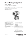
Tank Side Monitor NRF590
Inventory Control
Field device for tank sensor operation and monitoring and for
integration into inventory control systems
Software Version 02.03.
Application
The Tank Side Monitor NRF590 is a sensor integration
and monitoring unit for bulk storage tank gauging
applications.
It can be used with Micropilot level radars and combined
with other HART compatible devices.
The Tank Side Monitor offers the following functions:
• intrinsically safe (i.s.) power supply of the connected
devices
• parametrization of the connected devices
• display of the measured values
• tank calculations for accurate correction of the tank
distortions
TI402F/00/en/07.06
Features and benefits
• i.s. power supply and communication for
Micropilot M/S and Levelflex M level radars
• Connects up to 6 HART devices via i.s. 2 wire, for
example Prothermo for average temperature
measurement and Cerabar/Deltabar for HTMS
density applications
• Backlit graphical LCD display; operation via 3 optical
keys (touch control)
• User-friendly operating menu (multi-lingual)
• Interfaces to FuelsManager SCADA tank inventory
system via RTU 8130
• Provides communication to PLC, DCS and SCADA
systems
• Various industry standard communication protocols,
including
– Sakura V1
– EIA-485 Modbus
– Whessoematic WM 550
– BPM (compatible with Enraf systems)
• Approved for use in explosion hazardous areas
• Weights & Measure-approved for use in custody
transfer applications
Table of Contents
Function and system design. . . . . . . . . . . . . . . . . . . . . 3
Ambient conditions . . . . . . . . . . . . . . . . . . . . . . . . . . 23
Application . . . . . . . . . . . . . . . . . . . . . . . . . . . . . . . . . . . . . . . . . . 3
Operating principle . . . . . . . . . . . . . . . . . . . . . . . . . . . . . . . . . . . . 3
System Integration
(typical example) . . . . . . . . . . . . . . . . . . . . . . . . . . . . . . . . . . . . . 3
HART interface . . . . . . . . . . . . . . . . . . . . . . . . . . . . . . . . . . . . . . . 4
Power supply for HART instruments . . . . . . . . . . . . . . . . . . . . . . . 4
Operation of HART instruments . . . . . . . . . . . . . . . . . . . . . . . . . . 4
Typical Tank calculations . . . . . . . . . . . . . . . . . . . . . . . . . . . . . . . 5
Corrections . . . . . . . . . . . . . . . . . . . . . . . . . . . . . . . . . . . . . . . . . 7
Flow calculation
(in preparation) . . . . . . . . . . . . . . . . . . . . . . . . . . . . . . . . . . . . . . 7
Overfill protection . . . . . . . . . . . . . . . . . . . . . . . . . . . . . . . . . . . . 7
Ambient temperature . . . . . . . . . . . . . . . . . . . . . . . . . . . . . . . . .
Storage temperature . . . . . . . . . . . . . . . . . . . . . . . . . . . . . . . . . .
Ingress protection . . . . . . . . . . . . . . . . . . . . . . . . . . . . . . . . . . .
Electromagnetic compatibility (EMC) . . . . . . . . . . . . . . . . . . . . .
Overvoltage protection . . . . . . . . . . . . . . . . . . . . . . . . . . . . . . . .
Inputs and outputs . . . . . . . . . . . . . . . . . . . . . . . . . . . . 8
Non IS inputs and outputs . . . . . . . . . . . . . . . . . . . . . . . . . . . . . . 8
IS inputs and outputs . . . . . . . . . . . . . . . . . . . . . . . . . . . . . . . . . . 8
Fieldbus Protocols . . . . . . . . . . . . . . . . . . . . . . . . . . . . . . . . . . . . 9
Values transmitted by the Field Protocols . . . . . . . . . . . . . . . . . . 10
Technical data of the non-IS inputs and outputs . . . . . . . . . . . . . 11
Technical Data of the IS inputs and outputs . . . . . . . . . . . . . . . . 12
Auxiliary energy . . . . . . . . . . . . . . . . . . . . . . . . . . . . 13
AC supply . . . . . . . . . . . . . . . . . . . . . . . . . . . . . . . . . . . . . . . . . 13
DC supply . . . . . . . . . . . . . . . . . . . . . . . . . . . . . . . . . . . . . . . . . 13
Power consumption . . . . . . . . . . . . . . . . . . . . . . . . . . . . . . . . . . 13
Fuse . . . . . . . . . . . . . . . . . . . . . . . . . . . . . . . . . . . . . . . . . . . . . . 13
Grounding . . . . . . . . . . . . . . . . . . . . . . . . . . . . . . . . . . . . . . . . . 13
23
23
23
23
23
Mechanical construction . . . . . . . . . . . . . . . . . . . . . . 24
Design, dimensions . . . . . . . . . . . . . . . . . . . . . . . . . . . . . . . . . .
Construction . . . . . . . . . . . . . . . . . . . . . . . . . . . . . . . . . . . . . . .
Weight . . . . . . . . . . . . . . . . . . . . . . . . . . . . . . . . . . . . . . . . . . .
Cable entries . . . . . . . . . . . . . . . . . . . . . . . . . . . . . . . . . . . . . . .
24
24
24
24
Human interface . . . . . . . . . . . . . . . . . . . . . . . . . . . . 25
Display and operating elements . . . . . . . . . . . . . . . . . . . . . . . . . 25
Operating concept . . . . . . . . . . . . . . . . . . . . . . . . . . . . . . . . . . . 27
Operation with "ToF Tool Field Tool Package" . . . . . . . . . . . . . . 27
Certificates and Approvals . . . . . . . . . . . . . . . . . . . . . 28
CE mark . . . . . . . . . . . . . . . . . . . . . . . . . . . . . . . . . . . . . . . . . .
Ex approvals . . . . . . . . . . . . . . . . . . . . . . . . . . . . . . . . . . . . . . .
Custody transfer approvals . . . . . . . . . . . . . . . . . . . . . . . . . . . . .
External standards and guidelines . . . . . . . . . . . . . . . . . . . . . . . .
28
28
28
29
Ordering information. . . . . . . . . . . . . . . . . . . . . . . . . 30
Product structure . . . . . . . . . . . . . . . . . . . . . . . . . . . . . . . . . . . . 30
Accessories . . . . . . . . . . . . . . . . . . . . . . . . . . . . . . . . 32
Electrical connection - non-i.s. terminals. . . . . . . . . . 14
Terminal assignment of the field protocol/host side . . . . . . . . . . . 14
Connection of the field protocols . . . . . . . . . . . . . . . . . . . . . . . . 16
Grounding of the fieldbus screen . . . . . . . . . . . . . . . . . . . . . . . . 16
Connection of the auxiliary energy . . . . . . . . . . . . . . . . . . . . . . . 17
Connection of the non-i.s.
4 ... 20 mA analogue input . . . . . . . . . . . . . . . . . . . . . . . . . . . . 17
Connection of the non-i.s.
4 ... 20 mA analogue output . . . . . . . . . . . . . . . . . . . . . . . . . . . . 17
Connection of the discrete in and output . . . . . . . . . . . . . . . . . . 17
Electrical connection - i.s. terminals . . . . . . . . . . . . . 18
Terminal assignment . . . . . . . . . . . . . . . . . . . . . . . . . . . . . . . . . 18
Connection of HART instruments . . . . . . . . . . . . . . . . . . . . . . . . 19
Spot RTD . . . . . . . . . . . . . . . . . . . . . . . . . . . . . . . . . . . . . . . . . . 19
Performance characteristics. . . . . . . . . . . . . . . . . . . . 20
Accuracy . . . . . . . . . . . . . . . . . . . . . . . . . . . . . . . . . . . . . . . . . . 20
Resolution . . . . . . . . . . . . . . . . . . . . . . . . . . . . . . . . . . . . . . . . . 20
Scan time . . . . . . . . . . . . . . . . . . . . . . . . . . . . . . . . . . . . . . . . . . 20
Installation conditions . . . . . . . . . . . . . . . . . . . . . . . . 21
Wall mounting . . . . . . . . . . . . . . . . . . . . . . . . . . . . . . . . . . . . . . 21
Mounting on vertical rail . . . . . . . . . . . . . . . . . . . . . . . . . . . . . . 21
Mounting on horizontal rail . . . . . . . . . . . . . . . . . . . . . . . . . . . . 22
2
Discrete I/O modules . . . . . . . . . . . . . . . . . . . . . . . . . . . . . . . . 32
Rail mounting kit . . . . . . . . . . . . . . . . . . . . . . . . . . . . . . . . . . . . 35
Supplementary Documentation . . . . . . . . . . . . . . . . . 36
Special Documentation . . . . . . . . . . . . . . . . . . . . . . . . . . . . . . .
Technical Information . . . . . . . . . . . . . . . . . . . . . . . . . . . . . . . .
Operating Instructions . . . . . . . . . . . . . . . . . . . . . . . . . . . . . . . .
Safety Instructions . . . . . . . . . . . . . . . . . . . . . . . . . . . . . . . . . . .
Control Drawings . . . . . . . . . . . . . . . . . . . . . . . . . . . . . . . . . . .
36
36
36
37
37
Function and system design
Application
The Tank Side Monitor NRF590 is a field device for the integration of tank sensors into tank inventory systems.
It is used in tank farms, terminals and refineries.
Especially, it can be used in connection with Micropilot M level radars (for inventory control) and Micropilot S
high accuracy level radars (for custody transfer applications).
Operating principle
The Tank Side Monitor is typically installed at the bottom of the tank and allows to access all connected tank
sensors.
Typical process values measured by the sensors are:
• level
• temperature (point and/or average)
• water level (measured by capacitive probe)
• hydrostatic pressure (for hydrostatic tank gauging, "HTG", or hybrid tank measurements, "HTMS")
• secondary level value (for critical applications)
The Tank Side Monitor collects the measured values and performs several configurable tank calculations. All
measured and calculated values can be displayed at the on-site display.
Via a field communication protocol, the Tank Side Monitor can transfer the values to an inventory control
system.
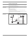
System Integration
(typical example)
HART (i.s.) multidrop
2-wire or 4-wire
FuelsManager
software
Host
communication
Micropilot
FMR
Power
Field
communication
RTU
Prothermo
NMT 539
optionally with
water bottom
probe
Tank Side
Monitor
HART (i.s.)
Deltabar
PMD
L00-NRF590-14-00-08-en-010
3
HART interface
IS (intrinsically safe)
HART Master for measuring device connection
Non-IS
(if selected by order code)
user settable:
• HART Master
• HART Slave (active 4-20 mA when address is "0")
Power supply for HART
instruments
The Tank Side Monitor provides intrinsically safe power for 2-wire tank sensors. It also can provide intrinsically
safe power for the 4-wire instrument Micropilot S.
Operation of HART
instruments
For the following instruments, the operating menu can be accessed on the display of the Tank Side Monitor:
•
•
•
•
•
•
•
•
•
•
Micropilot M: FMR230/231/240/244/245
Micropilot S: FMR530/531/532/533/540
Prothermo: NMT532/535/536/537/538
Prothermo: NMT539 (including Water Bottom Probe)
Whessoe Varec 1646 Temperature Transmitter
Cerabar M: PMC/PMP4x
Cerabar S: PMC/PMP7x
Cerabar: PCM/PMC73x/63x
Deltabar: PMD/FMD23x/63x
Deltabar S: PMD/FMD7x
Any other HART instrument can be operated via the Generic HART menu (allowing all 4 universal HART
values to be accessed).
4
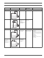
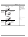
Typical Tank calculations
Setup preset
Installation example
Sensors
measured/
calculated values
required parameters
• Level sensor
• level
• Tank Ref Height
Direct level measurement
Level only
Micropilot
Tank Ref Height
Tank Side
Monitor
L00-NRF590-14-00-08-yy-002
Level + Temperature
Micropilot
Prothermo
Tank Side
Monitor
• level
• Level sensor
• Temperature sensor • temperature
(RTD or
HART device;
optionally with bottm
water probe)
L00-NRF590-14-00-08-yy-003
Hybrid Tank Measuring System (HTMS)
HTMS + P1
• Level sensor
• Pressure sensor
(P1, bottom)
Micropilot
Tank Ref Height
Tank Side
Monitor
P1 Position
P1
• level
• density of the measured
medium (calculated)
• Tank Ref Height
• P1 Position
• Min HTMS
(minimum level at which HTMS
measurement is possible; should be
slightly above the position of the P1
sensor)
• local gravity
• vapour density
• air density
• P3 Position (only for the "HTMS +
P1,3" mode)
L00-NRF590-14-00-08-yy-004
HTMS + P1,3
!
• Level sensor
• Pressure sensor
(P1, bottom)
• Pressure sensor
(P3, top)
P3
Micropilot
P3 Position
Note!
This mode should be
used in nonatmospheric tanks (e.g.
pressurised tanks)
Tank Side
Monitor
P1
L00-NRF590-14-00-08-yy-005
5
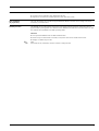
Setup preset
Installation example
Sensors
measured/
calculated values
required parameters
• Pressure sensor
(P1, bottom)
• level (calculated)
•
•
•
•
• level (calculated)
• density of the measured
medium (calculated)
• Tank Ref Height
• local gravity
• Min HTG Level
(minimum level at which HTG
measurement is possible; should be
slightly above the position of the P2
sensor)
• P1 Position
• P1-P2-Distance
• P3 Position (only for the "HTG
P1,2,3" mode)
Hydrostatic Tank Gauging (HTG)
HTG P1
Tank Side
Monitor
P1 Position
P1
L00-NRF590-14-00-08-yy-006
HTG P1,3
P3
!
Tank Side
Monitor
• Pressure sensor
(P1, bottom)
• Pressure sensor
(P3, top)
P3 Position
Note!
This mode should be
used in nonatmospheric tanks (e.g.
pressurised tanks)
Tank Ref Height
local gravity
density of the measured medium
Min HTG Level
(minimum level at which HTG
measurement is possible; should be
slightly above the position of the P1
sensor)
• P1 Position
• P3 Position (only for the "HTG P1,3"
mode)
P1 Position
P1
L00-NRF590-14-00-08-yy-009
HTG P1,2
Tank Side
Monitor
• Pressure sensor
(P1, bottom)
• Pressure sensor
(P2, middle)
P2
P1-P2 Distance
P1 Position
P1
L00-NRF590-14-00-08-yy-007
HTG P1,2,3
P3
!
Tank Side
Monitor
P3 Position
Note!
This mode should be
used in nonatmospheric tanks (e.g.
pressurised tanks)
P2
P1-P2 Distance
P1 Position
P1
L00-NRF590-14-00-08-yy-008
6
• Pressure sensor
(P1, bottom)
• Pressure sensor
(P2, middle)
• Pressure sensor
(P3, top)
Corrections
The Tank Side Monitor can automatically calculate the following corrections:
• Correction for the Hydrostatic Tank Deformation (HyTD)
• Temperature Correction for Thermal Expansion of the Tank Shell (CTSh)
Flow calculation
(in preparation)
The Tank Side Monitor can calculate the approximate flow based on the rate of level change and a linear
conversion, to volumetric flow.
Overfill protection
The NRF590 can be configured and used as part of an overfill protection system in comjunction with the
approved WHG operating mode of the Endress+Hauser FMR53x/54x radar devices (as described in the TÜV
test certificate for the FMR53x/54x WHG operating mode).
Overview
• Level input from FMR53x/54x via HART communication
• Discrete output via DO #A and/or DO #B (in conjunction with the AL1 alarm function block
• Analogue 4...20mA output via AO
!
Note!
AO #2 and DO #C (if available) cannot be used for overfill protection
7
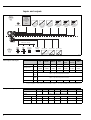
Inputs and outputs
V1
Modbus
WM550
Enraf BPM
Mark/Space
L&J
GPE
Non-i.s.
terminals
Ex d
Power AC/DC
Fieldbus
4...20 mA
Analogue In
(option)
4...20 mA
4...20 mA
Analogue Out 1 Analogue Out 2
with HART
(option)
(option)
Discrete In/Out A Discrete In/Out B Discrete Out C
(option)
(option)
(option)
HART (up to 24 mA)
FMR
Spot RTD
(option)
Pressure
transmitter
NMT
i.s.
terminals
Ex ia
Analogue In
Discrete In 1
Discrete In 2
4...20 mA
L00-NRF590-04-08-08-en-003
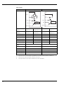
Non IS inputs and outputs
Analogue In
Analogue Out 1
Analogue Out 2
V1
Modbus
WM550
BPM
Mark/
Space
L&J
Tankway
GPE
-
option1)
-
standard
standard
standard
-
AI
1
AO
standard
+HART
option
+HART
standard
+HART
standard
+HART
standard
+HART
standard
+HART
standard
+HART
AO#2
standard
-
standard
-
-
-
standard
-
-
Discrete In/Out A DI#A
DO#A
option, s. pos. 50 of the product structure
Discrete In/Out B DI#B
DO#B
option, s. pos. 60 of the product structure
Discrete Out C
1)
DO#C
standard
-
-
-
see pos. 20 option 4 of the product structure; Modbus without in- or output does not provide an Ex d HART bus!
IS inputs and outputs
HART
V1
Modbus
WM550
BPM
standard
standard
standard
standard
IS RTD
8
-
Mark/Space L&J Tankway
standard
GPE
standard
standard
option, s. pos. 40 of the product structure
IS Discrete In 1 IS DI#1
standard
standard
standard
standard
standard
standard
standard
IS Discrete In 2 IS DI#2
standard
standard
standard
standard
standard
standard
standard
IS Analogue In
standard
standard
standard
standard
standard
standard
standard
IS AI
Fieldbus Protocols
The Tank Side Monitor NRF590 supports all of the following industry standard communication protocols
allowing it to be integrated with existing instrumentation and connect to host computer systems without the
need for additional hardware. These protocols allow for piece-by-piece replacement and upgrading of older
technologies to modern radar solutions.
Sakura V1
V1 protocol provides a standard form of digital communication via a two-wire system. V1 was brought to the
market by Sakura Endress and meets the demands of the Japanese market.
The Tank Side Monitor implementation of the V1 slave protocol supports various old and new V1 protocols:
• V1 (new V1)
• MDP (old V1)
• BBB (old V1)
• MIC+232 (old V1) (in preparation)
EIA-485 (RS485) Modbus
In Modbus, the flow of data between two devices uses a master/slave protocol. The NRF590 acts as a Modbus
slave and runs on the EIA-485 (RS) version of the MODBUS communications board. Modbus provides Varec
MFT parameter mapping for easier setup in retrofit applications. It provides direct connection to PLC and DCS
systems.
Whessoematic WM550
The WM550 protocol provides a standard form of digital communication via dual current loops. WM550 was
developed by Endress+Hauser (formerly Whessoe) to facilitate communications to transmitters installed on
mechanical float and tape gauges. It is a two-wire system and the only protocol with a redundant loop.
BPM
The Bi-Phase Mark (BPM) protocol provides compatibility to Enraf systems by emulating the Enraf GPU-BPM
protocol. The NRF590 is fully compatible to ENRAF (802, 812), 811, 854 and 954 series servo gauges, 813
MGT (mechanical gauge transmitter), 872, 873 and 973 series Radar gauges, 874 AIM (Analogue Input
Module) and the 875 VCU (Valve Command Unit).
Mark/Space
The Mark/Space protocol provides compatibility with Varec transmitters using a standard form of digital
communication via a voltage mode bus. Mark/Space was developed to facilitate communication to transmitters
installed on mechanical float and tape gauges. It supports product level, temperature and discrete inputs.
L&J Tankway
L&J Tankway protocol provides a standard form of digital communication via a voltage mode bus. Tankway
supports product level, temperature and discrete inputs.
GPE
GPE protocol provides a standard form of digital communication via a current loop. It is compatible with L&J
and GPE mechanical float and tape and servo instrumentation.
9
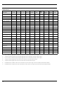
Values transmitted by the
Field Protocols
The following values can be transmitted by the communication protocols:
Symbol
V1 - old
V1 - new
Modbus
WM550
BPM
Mark/
Space
L&J
Tankway
Basic
L&J
Tankway
Servo
GPE
Level
L
yes
yes
yes
yes
yes
yes
yes
yes
yes
Temperature (Product)
TP
yes
yes
yes
yes
yes
yes
yes
yes
yes
Observed Density
Dobs
-
yes
yes
yes
yes
-
-
yes
-
Water Level
LW
-
yes
yes
yes
yes
-
-
yes
-
yes
yes1
yes
-
-
-
-
1)
-
-
-
-
-
Tank Value
Pressure 1 (Bottom)
P1
-
yes
Pressure 2 (Middle)
P2
-
yes
yes
yes
Pressure 3 (Top)
P3
-
yes
yes
yes
yes
-
-
-
-
yes
yes
1
-
-
-
-
-
-
-
-
-
-
Measured Level
LM
-
-
Level Correction
LC
-
-
yes
yes1
Percentage Level
L%
-
-
yes
yes
-
-
-
-
-
yes
yes
1
yes
-
-
-
-
yes
yes1
yes
-
-
-
-
1
-
-
-
-
-
Vapour Temperature
Air Temperature
TV
TA
-
yes
-
Level Flow Rate
(Rate of change of level)
-
-
yes
yes
Volumetric Flow Rate
-
-
yes
yes1
-
-
-
-
-
General Purpose Value 1
GP1
-
yes
yes
yes1
-
-
-
-
-
General Purpose Value 2
GP2
-
yes
yes
yes1
-
-
-
-
-
General Purpose Value 3
GP3
-
-
yes
yes1
-
-
-
-
-
General Purpose Value 4
GP4
-
-
yes
yes1
-
-
-
-
-
T(1) to T(16)
-
yes
yes
T(1) to T(15)
-
-
-
-
-
Alarm/Discrete Values
yes2)
yes2
yes
yes
yes3)
yes4)
yes5)
yes5
-
Discrete Output Control
-
-
yes
-
-
-
-
-
1
-
4-20mA6)
yes
Level %
-
-
Temp7)
-
4-20mA6
KA 246F
KA 246F
KA 245F
KA 247F
KA 248F
KA 249F
KA 250F
KA 250F
KA 251F
Multi-Element
Temperatures
Additional
Protocol Documentation
1)
Only accessible through WM550 extended tasks (51&52); not available on older control room systems.
2)
The protocol allows 2 alarm and 4 general purpose flags which can be connected to any alarm or discrete input.
3)
Level L & H alarm, 4 alarms and 2 general purpose flags which can be connected to any alarm or discrete input.
4)
The protocol allows 2 digital alarm values which can be connected to any alarm or discrete input.
5)
The protocol allows 2 digital values which can be connected to any alarm or discrete input.
6)
One additional value "4-20mA" which can be connected to any value, however range of value sent is limited (see KA 246F for details).
7)
One additional value "Temp2" which can be connected to any value, however the range of value sent is limited (see KA 250F for details).
10
Technical data of the non-IS
inputs and outputs
Analogue 4...20 mA input (option, s. pos. 20 of the product structure)
Internal load (to ground)
110 Ω
Measuring range
0 ... 26 mA
Accuracy
±15 µA (after linearisation and calibration)
Analogue 4...20 mA outputs
Output current
3 ... 24 mA
Output voltage
U = 24 V - ILOAD 400 Ω
Output load
max. 500 Ω
Accuracy
±15 µA (after linearisation and calibration)
HART
options1)
• Slave, address # 0:
4 ... 20 mA active
• Slave, address #1 - #15:
fixed current (user selectable)
• Master:
max. current (≤ 24 mA) selectable by user;
typically 6 HART instruments (each 4 mA) can be connected2)
1)
The second analogue output (available for V1, WM550 and GPE) has no HART option.
2)
Start-up current of the HART instruments has to be taken into account
Discrete inputs/outputs A and B
The Tank Side Monitor can be equipped with 1 or 2 discrete I/O modules.
Available types: see position 50 and 60 of Product Structure or chapter "Accessories".
Discrete output C (for V1 protocol)
Load voltage
3 ... 100 V
Load current
max. 500 mA
Type of contact
mechanical latching relay
Isolation voltage
1500 V
Approvals
UL, CSA
11
Technical Data of the IS inputs
and outputs
HART input loop
Source voltage
U = 25 V - ILoad x 333 Ω (typically)
total Imax
Start-up currents of all connected HART devices may not exceed a total of 27 mA
connectable sensors
depending on current consumption (including start-up current)
Spot RTD input (option, s. pos. 40 of the product structure)
Measuring range
10 ... 600 Ω
Excitation current
typ. 400 µA, max. 2000 µA
Nominal value
Tempmin
Tempmax
Accuracy1)
Pt100 (385) IEC751
Pt100 (389)
Pt100 (392) IPTS-68
100 Ω @ 0 °C (≈ 32 °F)
-200 °C (≈ -330 °F)
+600 °C (≈ +1110 °F)
±0.1 °C (≈ ± 0.2 °F)
Cu90 (4274)
100 Ω @ 25 °C (≈ 77 °F)
-100 °C (≈ -150 °F)
[90 Ω @ 0 °C (≈ 32 °F)]
+250 °C (≈ +480 °F)
±0.1 °C (≈ ± 0.2 °F)
Ni120 (672)
120 Ω @ 0 °C (≈ 32 °F)
-60 °C (≈ -75 °F)
+180 °C (≈ +350 °F)
±0.1 °C (≈ ± 0.2 °F)
Ni100 (618) DIN
43760
100 Ω @ 0 °C (≈ 32 °F)
-60 °C (≈ -75 °F)
+180 °C (≈ +350 °F)
±0.1 °C (≈ ± 0.2 °F)
Type of Sensor
1)
Accuracy of converter, may be influenced by element accuracy
IS Analogue 4...20 mA input (option, s. pos. 70 of the product structure)
Source voltage
U = 25 V - ILoad x 333 Ω (typically)
Internal load (to ground)
100 Ω
Measuring range
0 ... 26 mA
Accuracy
±15 µA (after linearisation and calibration)
Usage
Source for Discrete Inputs / Source for 4 ... 20 mA loop device
Discrete inputs (option, s. pos. 70 of the product structure)
12
Active voltage ("closed circuit")
min. 9 V (default)
In-active voltage ("open circuit")
max. 7 V (default)
Active high current
4 mA
Switching hysteresis
2V
Auxiliary energy
AC supply
55 ... 264 VAC; insensitive to polarity / CSA approved: 55 ... 250 VAC
DC supply
18 ... 55 VAC/DC
Power consumption
•
•
•
•
Fuse
Internal (on primary power)
Grounding
The NRF590 must be grounded to the tank potential before communication and power connections are made.
The connections (A ≥ 4mm2) from each outer ground plug of the NRF590 to the tank ground must be made
before any other wiring connections are made. All grounding must be compliant with local and company
regulations and checked before the equipment is commissioned.
370 mA @ 24 VDC
200 mA @ 48 VDC
75 mA @ 125VAC
45 mA @ 220 VAC
A > 4 mm
2
Tank Ground
L00-NRF590-04-08-08-en-004
13
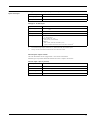
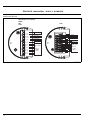
Electrical connection - non-i.s. terminals
Terminal assignment of the
field protocol/host side
Standard (not certified)
ATEX
FM
CSA
TIIS
01 L/+
02 N/-
Power
01 L/+
04 A1/+
05 A2/06 B1/+
07 B2/00 S
08 C1
Digital I/O A
11 C4
12 C5
13 C6
04 A1/+
05 A2/-
Power
Digital I/O A
Digital I/O B
06 B1/+
Cable screen
07 B2/00 S
Digital I/O B
Cable screen
08 C1
09 C2
09 C2
10 C3
02 N/-
Field protocol
and
Analog I/O
(for details
see table)
10 C3
11 C4
12 C5
13 C6
14 C7
Field protocol
and
Analog I/O
(for details
see table)
15 C8
14 C7
15 C8
L00-NRF590-04-08-08-en-002
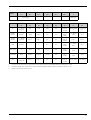
14
Terminal
01
L/+
02
N/Power supply
04
A1/+
05
A2/-
06
B1/+
07
B2/-
00
S
Discrete I/O A
+
Discrete I/O A
-
Discrete I/O B
+
Discrete I/O B
-
Cable screen
08
C1
09
C2
10
C3
11
C4
12
C5
13
C6
14
C7
15
C8
V1
4 ... 20 mA
output1) #2
V1A
V1B
0 V1
0V
4 ... 20 mA
output #1
+ HART
discrete output
1C
discrete output
2C
EIA-485
Modbus
not used2)
485-B
485-A
0V
0 V1
4 ... 20 mA
output3)
+HART
4 ... 20 mA
input3
+24 V1
Whessoe
WM550
4 ... 20 mA
output1 #2
Loop 1-
Loop 1+
0 V1
0V
4 ... 20 mA
output #1
+HART
Loop 2-
Loop 2+
BPM
not used2
T
T
0V
0 V1
4 ... 20 mA
output
+ HART
4 ... 20 mA
input
+24 V1
Mark/Space
V+
Space
Mark
0 V (V-)
0 V1
4 ... 20 mA
output
+ HART
4 ... 20 mA
input
+24 V1
L&J Tankway
Power
Encoder
Computer
Ground
0 V1
4 ... 20 mA
output
+ HART
4 ... 20 mA
input
+24 V1
GPE
4 ... 20 mA
output1 #2
Loop 1-
Loop 1+
0 V1
0V
4 ... 20 mA
output #1
+ HART
do not connect
do not connect
1)
In case an "Ex d" rated 4-wire level gauge version is used, the power supply can be obtained from these terminals (21V ±10%).
2)
The internal voltage at this terminal is 0 V, however, shielding and signal common should be connected to terminal 11 or 12.
3)
option, s. pos. 20 of the product structure
15
Connection of the field
protocols
Sakura V1
The V1 protocol provides 2 wire communication allowing up to 10 devices to operate on a loop. V1 connects
to terminals 9-10.
Max. distance: 6000 m
EIA-485 Modbus
The NRF590 protocol uses a shielded 3-wire EIA-485 hardware interface to communicate with the modbus
master. EIA-485 is a high speed, differential communications network that allows up to 32 devices to operate
on one network.
• Using one shielded twisted pair of 18 AWG wire, connect the EIA-485 at terminal 9 and 10.
• Termination of the EIA-485 bus at the NRF590 can be set in the operating menu (only enable on end device
in a loop)
• Connect the 3rd wire from the control system signal common (0V) to terminal 8.
• Max distance: 4000 ft (1300 m)
Whessoematic WM550
The WM550 protocol provides 2 wire, current loop communication and allows up to 16 devices per loop. For
redundancy (safety function) two wire pairs are used. They always transmit the same values. The WM550loops connect to terminals 9 - 10 and 14 - 15.
Max. distance: 7000 m
BPM
The BPM protocol provides 2 wire communication allowing up to 10 devices to operate on a loop. BPM
connects to terminals 9-10.
Max. distance: 10000 m
Mark/Space
For a NRF590 using the Mark/Space field communications option, the following additional wiring connections
must be made:
• Run 2 twisted pairs (one power, one communication) of 18 AWG wire (Mark/Space wires) into the upper
terminal compartment through one of the conduit entries along with the 48 Vdc power wiring.
• Connect the Mark line to terminal 10 and the Space line to terminal 9.
• Connect to power supply at terminals 8 and 11.
L&J Tankway
Including power and ground, L&J is a 4-wire system, allowing 50+ devices to be connected on the
communication bus. L&J connects to terminals 8 through 11.
GPE
The GPE protocol provides 2 wire current loop communication. GPE connects to terminal 9-10.
Grounding of the fieldbus
screen
16
The screen of the fieldbus cable should be connected to ground at both ends. If this is not possible due to signal
disruption by potential equalisation currents, it is advisable to connect the screen of the fieldbus cable to
terminal "00 S" at the NRF590 and to ground at the other end. The "00S" terminal provides a 500 V capacitor
between the cable screen and tank ground potential.
Connection of the auxiliary
energy
The Tank Side Monitor can be AC or DC supplied, depending on the installed power supply board. The AC
supply needs to be connected to the terminals marked L/+ (Line) and N/- (Neutral), corresponding with the
phase/line and neutral wire. DC supply can be connected to the same terminals, for which it is necessary to
connect the positive (+) to the terminal marked (L/+), and the negative to the terminal marked (N/-).
Connection of the non-i.s.
4 ... 20 mA analogue input
Depending on the selected fieldbus communication board, a non-i.s. self-powered or loop powered analogue
transmitter can be connected. The analogue signal for the loop powered transmitter can be connected to the
terminals 14 (-) and 15 (+24 Vdc). The maximum supply current for the analogue transmitter is limited to 24
mA. The analog signal for a self powered transmitter should be connected to terminals 11 or 12 and 14.
Loop powered (passive)
self powered (active)
14
11/12
+
+
e.g.
FMR
15
e.g.
FMR
14
L00-NRF590-04-00-08-en-019
Connection of the non-i.s.
4 ... 20 mA analogue output
For all field communication boards except the Modbus Option without analog in/output, a
non-i.s. 4.. .20mA output is available. Via Software settings, this analogue output can be connected to any
parameter in the Tank Side Monitor. The analogue output is available between terminals
13 (+) and 12 (-). From SW 02.01.xx onwards, an additional HART signal is available at terminal 13.
Connection of the discrete in
and output
The Tank Side Monitor can be equipped with up to 2 discrete I/O modules. These modules can be used for
interfacing to non-i.s. discrete in- or outputs. Input and output voltage and current ranges depend on the type
of selected module installed in the relevant I/O slot. Terminals 4 and 5 correspond to discrete I/O slot A,
terminals 6 and 7 correspond to discrete I/O slot B. For details on available I/O modules, see Page 32.
6 7
DIGITAL
AC OUTPUT 4 5
B
A
LOAD
L
AC SUPPLY
N
6 7
DIGITAL
DC OUTPUT 4 5
B
A
LOAD
+
DC SUPPLY
–
DIGITAL
AC INPUT
6 7
4 5
B
A
L
AC SUPPLY
N
DIGITAL
DC INPUT
6 7
4 5
B
A
+
DC SUPPLY
–
L00-NRF590-04-00-08-en-004
!
Note!
250 VAC is the maximum load that can be connected.
17
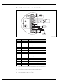
Electrical connection - i.s. terminals
Terminal assignment
NRF590 - i.s. terminal board
RTD
mA
24V
Internally
HART interconnected
sensor as one HART
fieldbus loop
For Micropilot
S-series only!
L00-NRF590-04-00-08-en-018
18
Terminal
Designation
Meaning
16
D+
+ RTD drive1)
17
S+
+ RTD sense1
18
S-
- RTD sense1,2)
19
D-
- RTD drive1,2
20
OPT1
Discrete Input 1
21
OPT2
Analog Input 1 (4 ... 20 mA)
22
OPT3
Discrete Input 2
23
OPT4
Option +24 V
24
H+
+HART comm.3)
25
H-
-HART comm.4)
26
H+
+HART comm.3
27
H-
-HART comm.4
28
H+
+HART comm.3
29
H-
-HART comm.4
30
P+
+ i.s. power for FMR S-series3 (terminal 2 of FMR)
31
P-
- i.s. power for FMR S-series4 (terminal 1 of FMR)
1)
These terminals should be left unconnected if RTD has not been selected in feature
40 of the product structure.
2)
For a 3-wire RTD, terminals 18 and 19 should be connected together.
3)
These terminals share the same HART signal.
4)
These terminals share the same i.s. 0 V signal.
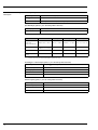
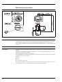
Connection of HART
instruments
Tank sensors
The Tank Side Monitor can interface to a maximum of 6 i.s. HART sensors.
All HART sensors are connected to one HART multi-drop communication loop.
In order to keep wiring simple, 3 interconnected terminal pairs are available. The terminal pairs are marked
respectively H+ and H-.
Power supply for Micropilot S
For supplying extra i.s. power to the FMR S-series radar, additional power terminals are available, marked as
P+ and P-. Although it is possible to use only 3 wires between the S-series radar and the NRF590, by combining
the P- and H- wires, it is recommended to use a double pair of screened and twisted cable.
Grounding of the cable screen (for Micropilot S)
The screen of the cable connecting the Micropilot S to the Tank Side Monitor should be grounded at the Tank
Side Monitor, not at the Micropilot S.
Tank Side Monitor
NRF 590 i.s. terminal board
16
17
18
19
D+
S+
SD-
20
21
22
23
OPT1
OPT2
OPT3
OPT4
24
25
26
27
+
H
+
H
-
28
29
30
31
+
-H
+
P
-
RTD
Micropilot S
i.s. module wiring
1 2 3 4
Internally
HART interconnected
sensor as one HART
fieldbus loop
+
4
- 3
+
2
- 1
1 2 3 4 5
1
2
For Micropilot
S-series only!
3
4
5
Tank potential
L00-NRF590-04-08-08-yy-007
Spot RTD
A spot RTD can be connected to the NRF590 if the
option is installed. For 4-wire connection, the RTD
must be connected to the 4 available terminals
marked D+, S+, S- and D-. For 3-wire connection,
the RTD should be connected to the same 4
terminals. The terminals D- and S- should be
connected together directly at the NRF590 terminals.
RTD
4 wire
RTD
3 wire
L00-NRF590-04-00-08-en-007
19
Performance characteristics
Accuracy
HART sensors
Accuracy of all data from connected HART sensors depends on the type and installation of instruments. The
use of the digital HART protocol prevents accuracy data degradation, as would be the case with analogue
(4...20 mA) sensors.
Spot RTD input, analogue inputs, analogue outputs
see above, "Technical data of the IS inputs and outputs
Resolution
Resolution of all measured data depends on sensor and communication settings. The following settings are
recommended for inventory and custody transfer applications:
Data type
Level
Units
Inventory control
Custody transfer
millimeters
1 mm
1 or 0.1 mm
meters
10 mm
1 or 0.1 mm
feet
0.01 ft
0.01 ft
inches
1" or 0.1"
0.01" or 0.001"
ft-in-16
1/16"
1/16"
°C
0.1 °C
0.1 °C
°F
0.1 °F
0.1 °F
Temperature
For purpose of consistency all internal calculations are performed in SI units.
Scan time
HART sensors
The data of connected HART sensors is constantly scanned and updated in the internal data base. The scanning
sequence is based on the priorities of the measurements (level - prio 1, temperature - prio 2, pressure - prio
3,...). Typically, a value change on the HART multidrop loop is displayed after a 2 seconds delay (for priority 1
values).
Spot RTD input
RTD resistance is measured and recalculated at least every second.
20
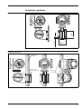
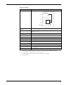
Installation conditions
Ø 8.6 (M8)
3.94"
(100 mm)
Wall mounting
3.94"
(100 mm)
L00-NRF590-17-00-06-xx-001
Mounting on vertical rail
3.5" (90 mm)
maximum
Rail mounting kit
(Order No.: 52013134)
Grounding
connections
L00-NRF590-17-00-06-en-002
21
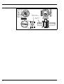
Mounting on horizontal rail
Rail mounting kit
(Order No.: 52013134)
Ø3.5" (90 mm)
maximum
L00-NRF590-17-00-06-en-003
22
Ambient conditions
Ambient temperature
-40 °C ... +60 °C (-40 °F ... +140 °F )
Storage temperature
-55 °C ... 85 °C (-67 °F...185 °F)
Ingress protection
IP65, Nema 4X
Electromagnetic compatibility
(EMC)
• Interference emission to EN 61326, Equipment class A
• Interference immunity to EN 61326
Use shielded signal lines for installation.
Overvoltage protection
Both interfaces of the NRF590 - the Ex ia and the Ex d side - are protected by internal 600 Vrms surge arresters
which have been tested against 10 kA transient discharges.
23
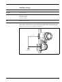
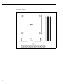
Mechanical construction
Design, dimensions
L00-NRF590-06-00-06-yy-001
Construction
The NRF590 housing has three separate compartments, one containing all electronics and two for electrical
connections. The enclosure is die-cast aluminum with an polyester coating and IP65 (NEMA 4) rating. The
upper terminal compartment and electronics compartment are designated for non-i.s. connections and
electronics and are rated EEx d.The lower terminal compartment is designated for i.s. wiring connections and
wiring only.
Weight
approx. 8 kg
Cable entries
The non-i.s. terminal compartment has 3 cable entries. The threading in this terminal compartment enclosure
is M20x1.5.
All intrinsically designated wiring has to be terminated in the i.s. terminal compartment. For the i.s. wiring,
two M25x1.5 cable entries are available.
The internal diameter of the cable entry is 16 mm.
For accommodating various types of cable glands or cable conduit (rigid or flexible), the following sizes of cable
gland adapters are optionally available:
•
•
•
•
M20x1.5
G½
½" NPT
¾" NPT (max. 2 cable entries)
All adapters are rated EEx d and can be used for either cable connection. When installing, properly seal all ports
to prevent moisture or other contamination from entering the wiring compartments.
24
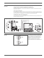
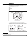
Human interface
Display and operating
elements
Liquid crystal display (LCD)
Four lines with 20 characters each. Display contrast adjustable through key combination. The backlight of the
display is activated during operation for user defined time (30 sec ... continuous backlight).
The following display languages can be selected by the user:
•
•
•
•
•
•
•
•
English
German
Japanese1)
Simplified Chinese2)
Dutch
Spanish
French
Italian
L00-NRF590-07-00-00-en-001
Optical keys
The optical keys allow the Tank Side Monitor to be operated without the housing being opened.
From Software Version 02.xx.xx onwards they function as softkeys, i.e. their meaning varies depending on the
current position within the operating menu. The meaning is indicated by softkey symbols in the bottom line of
the display:
Softkey symbols
to previous
parameter
to next
parameter
edit current
parameter
move
downwards
move
upwards
mark current
selection
Meaning
L00-NRF590-07-00-00-en-003
1)
2)
Japanese font: JIS X 208-1997 including Hiragana, Katakana asnd Kanji
Chinese font: GB18030, CITS Committee approved
25
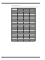
Format of decimal numbers
The number of decimal places displayed can be selected from three resolution presets (high, normal, low)
VAlue
resolution preset
low
normal
high
mm
xxxxx
xxxxx
xxxxx.x
cm
xxxx.x
xxxx.x
xxxx.x
m
xx.xxx
xx.xxx
xx.xxxx
in
xxxx.x
xxxx.x
xxxx.xx
ft
xxx.xxx
xxx.xxx
xxx.xxxx
ft-in-8
xx’xx"x/8
xx’xx"x/8
xx’xx"x/8
ft-in-16
xx‘xx"xx/16
xx‘xx"xx/16
xx‘xx"xx/16
16ths
xxxxx
xxxxx
xxxxx.x
°C
xxx
xxx.x
xxx.xx
°F
xxx
xxx.x
xxx.xx
Pa
xxxxxxx
xxxxxxx
xxxxxxx
kPa
xxxx.x
xxxx.xx
xxxx.xxx
MPa
x.xxxx
x.xxxxx
x.xxxxxx
mbar
xxxxx
xxxxx
xxxxx.x
bar
xx.xxx
xx.xxx
xx.xxxx
psi
xxx
xxx.x
xxx.xx
inH20
xxxxx
xxxxx.x
xxxxx.x
kg/m3
xxxx.x
xxxx.xx
xxxx.xx
g/ml
x.xxxx
x.xxxx
x.xxxxx
lb/ft3
xx.xx
xx.xxx
xx.xxxx
°API
xxx.xx
xxx.xx
xxx.xxx
xx.xxx
xx.xxx
xx.xxxx
level units
temperature units
pressure units
density units
current units
mA
26
Operating concept
The Tank Side Monitor is operated via a four-layer menu. The structure of the menu accounts for typical
measuring tasks as well as for the individual instrument configuration and installation. In particular, the menu
contains dynamic function groups which are only indicated if the respective option is installed or the respective
instrument is connected. This structure ensures clarity and simple operation without restricting the scope of
functionality.
The appearance and meaning of the LCD change according to the current position within the menu.
status
symbols
primary value
with bargraph
Measure Value Display
secondary value
with alarm state indication
softkey symbols
menu position indicator
Access mode
(here: "User")
Main Menu
selection list
with scroll bar
data type ("configuration”)
Option menu with
parameter Display
parameter name
parameter value
marked parameter value
Editing a parameter
with selection list
selection list
with scroll bar
L00-NRF590-07-00-00-en-004
Operation with "ToF Tool
Field Tool Package"
The Tank Side Monitor can also be operated via the "ToF Tool - Field Tool Package". This program supports
commissioning, securing of data, signal analysis and documentation of the instruments. It is compatible with
the following operating systems: WinNT4.0, Win2000 and Win XP.
The "ToF Tool - Field Tool Package" supports the following functions:
• Online configuration of transmitters
• Loading and saving of instrument data (Upload/Download)
• Documentation of measuring point
27
Certificates and Approvals
CE mark
The measuring system meets the legal requirements of the EC-guidelines. Endress+Hauser confirms the
instrument passing the required tests by attaching the CE-mark.
Ex approvals
FM
FM XP - Class I, Div 1 Groups A-D;
Note the Installation Drawings ZD 084F and ZD 085F (IS 4-20 mA Option Module)
CSA
FM XP - Class I, Div 1 Groups A-D;
Note the Installation Drawings ZD 103F and ZD 104F (IS 4-20 mA Option Module)
ATEX
ATEX II 2 (1) G EEx d (ia) IIC T4;
Note the Safety Instructions XA 160F and XA 169F (IS 4-20 mA Option Module)
Custody transfer approvals
28
• NMi type approval
• NMi initial verification, type approval
• PTB initial verification, type approval
External standards and
guidelines
EN 60529
Protection class of housing (IP-code)
EN 61010
Safety regulations for electrical devices for measurement, control, regulation and laboratory use.
EN 61326
Emissions (equipment class B), compatibility (appendix A - industrial use)
API MPMS Ch. 3.1A
Standard Practice for Manual Gauging of Petroleum and Petroleum Products in Stationary Tanks.
API MPMS Ch. 3.1B
Standard Practice for Level Measurement of Liquid Hydrocarbons in Stationary Tanks by Automatic Tank
Gauging
API MPMS Ch. 3.3
Standard Practice fro Level Measurement of liquid Hydrocarbons in Stationary Pressurized Storage Tanks by
Automatic Tank Gauging
API MPMS Ch. 3.6
Measurement of Liquid Hydrocarbons by Hybrid Tank Measurement Systems
API MPMS Ch. 7.4
Static Temperature Determination Using Fixed Automatic Tank Thermometers
ISO 4266 / Part 1
Petroleum and liquid petroleum products - Measurement of level and temperature in storage tanks by
automatic methods - Part 1: Measurement of level in atmospheric tanks
ISO 4266 / Part 3
Petroleum and liquid petroleum products - Measurement of level and temperature in storage tanks by
automatic methods - Part 3: Measurement of level in pressurized storage tanks (non refrigerated)
ISO 4266 / Part 4
Petroleum and liquid petroleum products - Measurement of level and temperature in storage tanks by
automatic methods - Part 4: Measurement of temperature in atmospheric tanks
ISO 4266 / Part 6
Petroleum and liquid petroleum products - Measurement of level and temperature in storage tanks by
automatic methods - Part 6: Measurement of temperature in pressurized tanks
ISO 15169
Petroleum and liquid petroleum products - Determination of volume, density and mass of the contents of
vertical cylindrical tanks by Hybrid Tank Measurement Systems
OIML - R85
Organisation Internationale de Métrologie Légale - Automatic level gauges for measuring the level of liquid in
fixed storage tanks.
29
Ordering information
Product structure
Ordering structure Tank Side Monitor NRF590
10
Certificates
A
6
U
S
K
Y
20
For non-hazardous areas
ATEX II 2 (1) EEx d (ia) IIC T4
CSA XP Cl. I, Div 1, Gr. A-D
FM XP Cl. I, Div 1, Gr. A-D
TIIS EEx d (ia) IIC T4 (in preparation)
Special version, to be specified
Field communication protocol
E
G
1
3
4
5
7
8
9
30
ENRAF BPM, non-IS 4-20mA input, non-IS 4-20mA HART output
GPE, non-IS 4-20mA HART output
WM550, non-IS 4-20mA output, Whessoe protocol with dual communication
Varec Mark/Space, non-IS 4-20mA input, non-IS 4-20mA HART output
Modbus w/o 4-20mA input or output, EIA 485
Modbus, non-IS 4-20mA input, non IS 4-20mA HART output, EIA 485
L&J, non-IS 4-20mA input, non-IS 4-20mA HART output
V1, non-IS 4-20mA output, non-IS 4-20mA HART output, relay output
Special version, to be specified
Power supply
A
B
Y
40
Power supply 18...55 VAC/DC
Power supply 55...264V AC
Special version, to be specified
Spot RTD option
0
1
9
50
Without RTD temperature input
With spot RTD temperature input, IS
Special version, to be specified
Discrete I/O Module A
A
B
C
D
E
G
H
J
K
R
Y
60
Without discrete input/output module A
Discrete input module A, 90...140V AC
Discrete input module A, 3...32V DC
Discrete input module A, 180...250V AC
Discrete input module A, 35...60V AC/DC
Discrete output module A, 24...250V AC
Discrete output module A, 3...60V DC
Discrete output module A, 24...140V AC
Discrete output module A, 4...200V DC
Relay output A, 0-100 VDC, 0-120VAC
Special version, to be specified
Discrete I/O Module B
A
B
C
D
E
G
H
J
K
R
Y
70
Without discrete input/output module B
Discrete input module B, 90...140V AC
Discrete input module B, 3...32V DC
Discrete input module B, 180...250V AC
Discrete input module B, 35...60V AC/DC
Discrete output module B, 24...250V AC
Discrete output module B, 3...60V DC
Discrete output module B, 24...140V AC
Discrete output module B, 4...200V DC
Relay output B, 0-100 VDC, 0-120VAC
Special version, to be specified
Additional intrinsically safe module
0
1
2
9
NRF590 -
30
Additional IS module not selected
Additional IS 4...20mA analogue input
Integrated 4...20mA input, two discrete inputs
Special version, to be specified
Product designation (part 1)
80
Glands/Entries - non IS
F
B
C
D
E
H
K
L
G
Y
90
2 x G 1/2" gland (in preparation)
2 x Ex d M20x1.5 entries
2 x Ex d G 1/2" entries
2 x Ex d 1/2" NPT entries
2 x Ex d 3/4" NPT entries
3 x Ex d M20x1.5 entries
3 x Ex d G 1/2" entries
3 x Ex d 1/2" NPT entries
3 x Ex d 3/4" NPT entries (in preparation)
Special version, to be specified
Gland/Entry - IS compartment
2
3
4
5
9
100
M25x1.5 glands, 13...18mm, intrinsically safe compartment
G 1/2" entries, intrinsically safe compartment
1/2" NPT entries, intrinsically safe compartment
3/4" NPT entries, intrinsically safe compartment
Special version, to be specified
Custody transfer type approvals
N
A
G
Y
110
Custody transfer type approval not selected
NMi type approval
PTB type approval
Special version, to be specified
Additional options
0
9
NRF590 -
Additional option not selected
Special version, to be specified
complete product designation
31
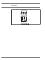
Accessories
Discrete I/O modules
Standard mechanical diagram for all I/O modules
1.70
(43.1)
1.00
(25.4)
1.00
(25.4)
.25
(6.35)
5
4
3+
2
1
.30
(7.6)
.200
(5.1)
.700
(17.8)
1.100
(27.9)
1.30
(43.1)
1.70
(43.1)
BOTTOM VI EW
.040 (1.0) DIA.
(5 PLACES)
.100
(2.5)
.40
(10.2)
L00-NRF590-00-00-08-en-001
32
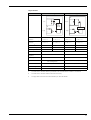
Output modules
AC voltage
DC voltage
+
1
1
VAC
VAC/DC
-
Zero
Voltage
Circuit
2
+
2
Amplifier
3
Logic
3
Logic
4
4
NRF590 order code1)
module A
NRF590 ****J******
NRF590 ****G******
NRF590 ****H******
NRF590 ****K******
NRF590 order code1
module B
NRF590 *****J*****
NRF590 *****G*****
NRF590 *****H*****
NRF590 *****K*****
Order Code2)
Colour of housing
Load voltage
52012959
52012960
52012961
52012962
black
black
red
red
24 ... 140 V AC
24 ... 250 V AC
3 ... 60 V DC
4 ... 200 V DC
Load current
30 ... 500 mA eff.
20 ... 500 mA eff.1
Typ. power
dissipation
1 W/A
1 ... 1.5 W/A
Meets IEEE472
Meets IEEE472
Type of contact
SPST normally open
Zero crossing turn-on
SPST normally open
Optical isolation
yes
yes
Isolation voltage
4000 V eff.
4000 V eff.
UL, CSA, CE, TÜV
UL, CSA, CE, TÜV
Transient protection
Approvals
3)
1)
This order code is valid if the module is preinstalled in the Tank Side Monitor as module A or module B
2)
This order code is valid if the module is ordered as an accessory.
3)
This upper limit of the load current is determined by the Tank Side Monitor.
33
Input modules
AC voltage
DC voltage
+
1
1
VAC/DC
VDC
–
2
Logic
2
+
Logic
3
3
Out
Ground
4
Out
-
Schmitt
Trigger
4
Ground
5
5
NRF590 order code1)
module A
NRF590 ****B******
NRF590 ****D******
NRF590 ****C******
NRF590 ****E******
NRF590 order code1
module B
NRF590 *****B*****
NRF590 *****D*****
NRF590 *****C*****
NRF590 *****E*****
Order code2)
Colour of housing
Input voltage
52012955
52012956
yellow
yellow
3)
52012957
52012958
white
white
3 ... 32 V DC
35 ... 60 V DC
90 ... 140 V AC
180 ... 264 V AC
22 kΩ
60 kΩ
22 kΩ
60 kΩ
Max. pick-up voltage
90 V AC
180 V AC
3 V DC
35 V DC
Min. drop-out voltage
25 V AC
50 VAC
1 V DC
9 V DC
Nominal input resistance
Input current @ max.
voltage
8 mA rms
8 mA rms
Typ. power dissipation
1 ... 1.5 W/A
1 ... 1.5 W/A
Meets IEEE472
Meets IEEE472
Optical isolation
yes
yes
Isolation voltage
4000 V rms
4000 V rms
UL, CSA, CE, TÜV
UL, CSA, CE, TÜV
Transient protection
Approvals
34
Schmitt
Trigger
1)
This order code is valid if the module is preinstalled in the Tank Side Monitor as module A or module B.
2)
This order code is valid if the module is ordered as an accessory.
3)
This upper limit of the input voltage is determined by the Tank Side Monitor.
Relay output module
1
VAC /VDC
2
+VCC
3
AMP
INPUT
GROUND
NRF590 order code1)
module A
NRF590 - ****R******
NRF590 order code1
module B
NRF590 - *****R*****
Order code2)
52026945
Colour of housing
red
Load voltage
0 ... 100 VDC / 0 ... 120 VAC
Load current
0 ... 500 mA3)
Max. contact resistance
Max. turn on/off
time4)
4
5
250 mΩ
1 ms
Min. life expectancy
500000 cycles
Type of contact
SPST normally open; mechanical relay
Isolation voltage
1500 Veff
Approvals
UL, CSA, CE, TÜV
1)
This order code is valid if the module is preinstalled in the Tank Side Monitor as module A or module B.
2)
This order code is valid if the module is ordered as an accessory.
3)
For inductive loads, use diode suppression or RC network to improve contact life.
4)
including debounce
35
Rail mounting kit
For rail mounting the Tank Side Monitor to vertical or horizontal pipe.
Order-Number: 52013134
L00-NRF590-00-00-06-en-001
36
Supplementary Documentation
Special Documentation
SD 001V
Special Documentation - Radar Tank Gauging
Technical Information
TI 006G
Technical Information Fuels Manager
TI 007G
Technical Information RTU 8130
TI 042N
Technical Information Prothermo NMT 539
TI 216P
Technical Information Cerabar S PMC 731 / PMP 731
TI 217P
Technical Information Cerabar S PMC 631 / PMP 635
TI 344F
Technical Information Micropilot S FMR 530/531/532/533
TI 345F
Technical Information Micropilot M FMR 230/231/240/244/245
Operating Instructions
BA 256F
Operating Instructions Tank Side Monitor NRF590
This document describes installation and commissioning of the Tank Side Monitor. Only those functions of the
operating menu are included, which are relevant for a usual application.
BA 257F
Tank Side Monitor - Description of Instrument Functions
This document contains a detailed description of all the functions of the Tank Side Monitor.
Safety Instructions
XA 160F
Tank Side Monitor NRF590 - ATEX II 2 (1) G
XA 169F
i.s. 4-20mA analogue input module for NRF590 - ATEX II 2 (1) G
Control Drawings
ZD 084F
Tank Side Monitor NRF590 - FM XP - Class I, Div. 1, Groups A-D
ZD 085F
i.s. 4-20mA analogue input module for NRF590 - FM XP - Class I, Div. 1, Groups A-D
ZD 103F
Tank Side Monitor NRF590 - CSA XP - Class I, Div. 1, Groups A-D
ZD 104F
i.s. 4-20mA analogue input module for NRF590 - CSA XP - Class I, Div. 1, Groups A-D
37
38
39
International Head Quarter
Endress+Hauser
GmbH+Co. KG
Instruments International
Colmarer Str. 6
79576 Weil am Rhein
Deutschland
Tel. +49 76 21 9 75 02
Fax +49 76 21 9 75 34 5
www.endress.com
[email protected]
TI402F/00/en/07.06
FM+SGML 6.0 ProMoDo