1
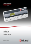
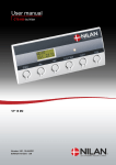
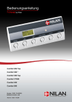
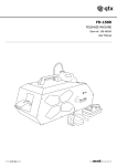
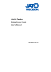
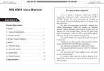
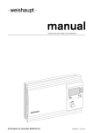
Installation instruction CTS 602 by Nilan VP 18 EK Version: 10.00, 13-04-2015 Software-version: 2.30 Table of contents Table of contents ............................................................................................................................ 2 Figure table .................................................................................................................................... 2 Introduction..................................................................................................................................... 3 Power supply .................................................................................................................................. 4 Assembly of VP 18 EK.................................................................................................................... 5 Condensation drain / water seal ..................................................................................................... 7 HWS ............................................................................................................................................... 8 Ducting ........................................................................................................................................... 9 Starting and set up of the CTS 602 control ................................................................................... 10 Starting ..................................................................................................................................... 10 Set up of the CTS 602 control ................................................................................................... 10 Activating the service menu ...................................................................................................... 11 Central heating.......................................................................................................................... 12 Hotwater ................................................................................................................................... 13 Air quality .................................................................................................................................. 14 Air exchange ............................................................................................................................. 15 Defrost ...................................................................................................................................... 16 Temp. control ............................................................................................................................ 17 Inlet control ............................................................................................................................... 18 Room control ............................................................................................................................ 19 Restart ...................................................................................................................................... 20 Preset ....................................................................................................................................... 21 Manual ...................................................................................................................................... 22 Modbus ..................................................................................................................................... 23 Datalog ..................................................................................................................................... 24 Faultfinding ................................................................................................................................... 25 Maintenance ................................................................................................................................. 26 Energy saving ............................................................................................................................... 29 Accessories/spare parts ............................................................................................................... 30 Figure table Figure 1: CTS 602 control ............................................................................................................... 4 Figure 2: Sketch of VP 18 EK ......................................................................................................... 6 Figure 5: Connection ...................................................................................................................... 8 Figure 6: Insulation of ducting ......................................................................................................... 9 Figure 4: CTS 602 control ............................................................................................................. 10 Figure 5: Headlines in the service menu ........................................................................................ 11 Figure 7: The "Hotwater" menu ..................................................................................................... 13 Figure 8: The "Air qulaity" menu ................................................................................................... 14 Figure 9: The "Air exchange" menu .............................................................................................. 15 Figure 10: The "Defrost" menu ..................................................................................................... 16 Figure 11: The "Temp. control" menu ............................................................................................ 17 Figure 12: The "Inlet control" menu............................................................................................... 18 Figure 13: The "Room control" menu ............................................................................................ 19 Figure 14: The "Restart" menu ..................................................................................................... 20 Figure 15: The "Preset" menu....................................................................................................... 21 Figure 16: The "Manual" menu ..................................................................................................... 22 Figure 17: The "Modbus" menu .................................................................................................... 23 Figure 18: The "Datalog" menu ..................................................................................................... 24 Figure 19: Filtershift ...................................................................................................................... 26 Introduction Please control that the following documents have been delivered together with the unit: - Directions for assembly & use (this document) - CTS 602 directions - Electrical chart Should you have any questions on how to operate the system, contact your nearest Nilan dealer, who you can find at www.nilan.dk/dealers VP 18 EK is a ventilation unit with heat recovery. The unit can yield up to 325m 3/h at 100Pa external back pressure. The energy in the exhaust air is being transferred to a 180L hot-water tank via a heat pump. When the water is heated the remaining energy is being transferred to the supply air. The unit is delivered with a G4 filter. In addition to this the unit can be equipped with different accessories e.g. hygrostat and filter box with pollen filter. Operating the unit is done with the 600 control. The control has many functions such as menu based attendance, week programme, time controlled filter guard and adjustment of the velocity of the ventilator. (Directions for the CTS 602 control is described in another document delivered with the unit.) VP 18 EK is delivered in a white-lacquered aluminum-zinc cabinet, tested and ready for use. Installation and start-up must be carried out by an authorized electrician. Ret til ændringer forbeholdes Side 3 af 30 Power supply Power supply including safety switch must be installed by an authorized electrician. The VP 18 EK -unit must be connected according to the attached electrical chart. The unit is delivered with 1m test cable for the CTS 602 panel. The panel should be connected to the CTS 602 control in the unit with cable type 2x2x0.25mm2 twisted in pairs. (Maximum length 50m). The CTS 602 panel must be placed dry and frost-proof. The panels’ integrated feeler prevents further cooling of the building if the primary heat-supply stops by stopping the ventilation if the panel feeler gets below a specific value. (Factory setting is 10°C; the value can be set from 1-20°C.) The built-in sensor of the panel prevents further cooling of the building in case of outage of the primary heating source. Should the panel sensor detect a temperature below the set value, the ventilation system will stop. (Factory set position is 10 °C, can be set to anything between 1 and 20 °C) Figure 1: CTS 602 control Ret til ændringer forbeholdes Side 4 af 30 Assembly of VP 18 EK When mounting the VP 18 EK -unit future service and maintenance should be considered. There is required a minimum of open space in front of the unit of 600mm measured from the front of the unit. In order to ease the mounting each of the connection pieces is labeled. Please notice the labels. The connection between the unit and the ducting should be a flexible transition. The unit should be leveled on a firm and vibration free bed. There should be at least 30mm to building components and other inventory. The unit itself is quiet and almost vibration less; still any potential vibration should be taken into account. It is important to establish a condensation drain from the unit to the outlet. The unit has an integrated water seal. The drain should be carried frost-proof and even downgrade to the outlet. The overflow from the safety valve should also be carried to the nearest outlet. If there is made a covering above the unit it should be easy to remove for maintenance purpose. Ret til ændringer forbeholdes Side 5 af 30 Figure 2: Sketch of VP 18 EK Ret til ændringer forbeholdes Side 6 af 30 Condensation drain / water seal The VP 18 EK unit is delivered with a 20mm condensation drain. (PVC, GF-fittings). The unit includes a water seal. The condensation drain should be carried with an even inclination of at least 1cm per metre, frost-proof to the nearest outlet. The overflow from the safety valve should also be carried to the nearest outlet. To avoid frost problems it can be necessary to supply the condensation drain with a heating cable. It is the plumbers’ responsibility to secure the drain. Ret til ændringer forbeholdes Side 7 af 30 HWS In order to prevent icing-up, it may be necessary to supply the condense outlet inside the building envelope with a heating cable. It is the installation contractor’s responsibility to frost protect the condense outlet. The hot-water tank is enamelled inside and equipped with a magnesium sacrificial anode. All branches have a ¾” thread socket. All water connections are connected in the bottom and must be done with flexible pipes. Hot-water circulation can be established if required, by mounting a check valve on the circulation branch of the tank. The branch should remain shut if there is not established hot-water circulation. There can be a significant heat-loss in the pipes due to the hot-water circulation which reduces the output of the heat pump considerably. To avoid this it is necessary to insulate the circulation pipe and the hot-water circuit with at least 30mm mineral wool or pipe insulation. Figure 5: Connection 12: Cold water ¾” 13: Hot water ¾” 14: Return supplementary coil ¾” 15: Inlet supplementary coil¾” 16: Circulation pipe connection¾” 19: Central heating inflow 20: Central heating return Ret til ændringer forbeholdes Side 8 af 30 Ducting We recommend that there are used ducts and fittings with rubber packing that meet sealing class B and that the connections between the unit and the ducting are made with 1 metre sound absorbing flexible transitions as regards sound reduction. The ducts should be shortened with a hacksaw or an angle grinder and laid out according to the working drawing. The ducts are typically laid out on the main beam of the truss frame and are secured with hole belts or they are being hanged in assembly belts. Please avoid any unnecessary area reductions and breaks of the ducting. The ducts should be insulated – in some cases with the ordinary attic-insulation. All ducts should be insulated with 100mm mineral wool to avoid heat loss and condensation. This also applies for flexible transitions. It is recommended that the insulation is carried out with 2 layers of 50mm. If the ducts are laid out in an unheated room it will cause condensation problems if the unit are turned off for a longer period of time as the hot air from the heated room will rise to the ducts and cause condensation which can cause damp problems. Loft insulationmaterial Duct Granulate Figure 6: Insulation of ducting The discharge duct is leading the exhaust air away either above the roof or through the outer wall. It is important that the roof cowl has at least the same open space as the duct leading to the roof cowl. A reduction at this place will cause an unnecessary pressure drop which can lead to a reduced ventilation output. The holes for the inlet- and exhaust valves should be cut according to the mounting-frame for the prescribed valve. The frame for the valve must be secured with screws before placing the valve in the frame. The valves are placed in accordance with the size, construction and use of the room. As an example we would not recommend placing an inlet valve just above people with sedentary work because the inlet air in some cases would be experienced as a draught. Ret til ændringer forbeholdes Side 9 af 30 Starting and set up of the CTS 602 control Starting Before starting the VP 18 EK please check all connections. Also check that the hot-water tank is filled with water. This is done by opening the hot-water tap. Set up of the CTS 602 control In this passage we will go through the service menu of the CTS 602 control. For daily use of the CTS 602 control please see the CTS 602 directions. (delivered together with the VP 18 EK). Use of the CTS602 panel: - press ESC to go one step back in the menu - press qp to move up or down in a menu or to adjust an activated menu - press ENTER to activate a menu - press ENTER to confirm a menu - press OFF to turn off the unit - press ON to turn the unit on Figure 4: CTS 602 control Ret til ændringer forbeholdes Side 10 af 30 Activating the service menu Press q and ENTER at the same time for 10 seconds. The service menu is now available. Press q multiple times until the panel shows SERVICE. Press ENTER to enter the service menu. It is now possible to move around in the menu by using pq. SERVICE ENTER CENTRAL HEATING HOTWATER AIR QUALITY AIR EXCHANGE DEFROST TEMP. CONTROL INLET CONTROL ROOM CONTROL RESTART OFF PRESET OFF MANUAL OFF MODBUS 30 ADR DATALOG INTV 10 Figure 5: Headlines in the service menu Ret til ændringer forbeholdes Side 11 af 30 Central heating ” ” indicates that the menu point flashes and can be set to another value SERVICE ENTER CENTRAL HEATING ENTER ENTER SELECT ON HOTWATER INTEGRAL TIME 10 ENTER AIR QUALITY SELECT RELAY 3 ENTER AIR EXCHANGE PUMP STOP 15 ENTER SELECT ”ON” SELECT ”OFF” The time can be adjusted from 0-25 minutes Choice: Relay 3 Relay 7 only if the plant is binary controlled DEFROST TEMP. CONTROL The time can be adjusted from 2-20 minutes INLET CONTROL ROOM CONTROL RESTART OFF PRESET OFF MANUAL OFF MODBUS 30 ADR DATALOG INTV 10 Figure 6: The "Central Heating" menu Ret til ændringer forbeholdes Side 12 af 30 Hotwater The ”Hotwater” menu enables you to select the electrical heating element in the main menu. When the heating element is set on ”on” there will appear a ”w” in the upper right corner of the panel in the main menu when the heating element is in use. ” ” indicates that the menu point flashes and can be set to another value Use of the CTS602 panel: - press ESC to go one step back in the menu - press qp to move up or down in a menu or to adjust an activated menu - press ENTER to activate a menu - press ENTER to confirm a menu - press OFF to turn off the unit - press ON to turn the unit on CENTRAL HEATING SERVICE ENTER HOTWATER AIR QUALITY AIR EXCHANGE ENTER EL SUP ON LEGIONEL OFF ENTER EL SUP ”ON” ENTER EL SUP ”OFF” ENTER LEGIONEL ”MON” ENTER LEGIONEL ”OFF” ENTER DEFROST TEMP. CONTROL A weekday can be chosen, where the hotwater will be warmed up to 65 °C between 01. 00 and 06. 00 o’clock. Fuction is not active. INLET CONTROL ROOM CONTROL RESTART OFF PRESET OFF MANUAL OFF MODBUS 30 ADR DATALOG INTV 10 Figure 7: The "Hotwater" menu Ret til ændringer forbeholdes Side 13 af 30 Air quality In the ”Air quality” menu it is possible to choose between 3 types of regulation: Humidity, Humidity + CO2 or OFF. On the CTS602 control panel, press: - ESC to return to the previous menu - qp to scroll upwards or downwards through the menus or to adjust the setting of an activated menu option - ENTER to activate a menu option - ENTER to confirm a menu option setting - OFF switch off the controls - ON to switch on the controls SERVICE ENTER CENTRAL HEATING HOTWATER AIR QUALITY ENTER FUNCTION OFF ENTER FUNCTION ”OFF” AIR EXCHANGE DEFROST Can be set to: OFF, HUMIDITY or HUM+CO2, when is mounted. TEMP. CONTROL INLET CONTROL ROOM CONTROL RESTART OFF PRESET OFF MANUAL OFF MODBUS ADR 30 DATALOG INTV 10 Figure 8: The "Air qulaity" menu Ret til ændringer forbeholdes Side 14 af 30 Air exchange In the ”Air exchange” menu it is possible to adjust 4 steps of ventilation speed (air volume). Inlet and exhaust is to be adjusted individually at each level. The inlet speed can be adjusted to a minimum and the exhaust can be adjusted to both a maximum and a minimum. It is possible to delay the starting of the fan in order to give time to the register to open. Use of the CTS602 panel: - press ESC to go one step back in the menu - press qp to move up or down in a menu or to adjust an activated menu - press ENTER to activate a menu - press ENTER to confirm a menu - press OFF to turn off the unit - press ON to turn the unit on SERVICE ENTER CENTRAL HEATING HOTWATER AIR QUALITY AIR EXCHANGE ENTER INLET MIN 0 DEFROST EXHAUST MIN 1 TEMP. CONTROL EXHAUST MAX 4 INLET CONTROL INLET >1 < 23% ROOM CONTROL INLET >2 < 40% RESTART OFF INLET >3 < 65% PRESET OFF INLET >4 < 100% MANUAL OFF EXHAUST >1 < 25% MODBUS 30 ADR EXHAUST >2 < 45% DATALOG INTV 10 EXHAUST >3 < 70% The lowest permissible ventilation step for fresh air/inlet (0-2) The lowest permissible ventilation step for outlet/exhaust (1-2) The highest permissible ventilation step for outlet/exhaust (3-4) Each ventilation step can be set as a percentage of maximum fan speed . EXHAUST >4 < 100% Figure 9: The "Air exchange" menu Ret til ændringer forbeholdes Side 15 af 30 Defrost In the ”Defrost” menu it is possible to chose how the unit should perform during defrosting of the evaporator in the exhaust. ” ” indicates that the menu point flashes and can be set to another value Use of the CTS602 panel: - press ESC to go one step back in the menu - press qp to move up or down in a menu or to adjust an activated menu - press ENTER to activate a menu - press ENTER to confirm a menu - press OFF to turn off the unit - press ON to turn the unit on SERVICE ENTER HOTWATER AIR QUALITY AIR EXCH ”LOW” AIR EXCHANGE ENTER AIR EXCH USER DEFROST TEMP. CONTROL ENTER START T6 -3 °C INLET CONTROL Adjustable temperature to start evaporator defrost on ROOM CONTROL T6 [-10…0] AIR EXCH ”USER” AIR EXCH ”OFF” Constant air flow during defrosting. Airflow stopped during defrosting (should be used when exhaust air temperature is less than 10°C). RESTART OFF PRESET OFF MANUAL OFF MODBUS 30 ADR DATALOG INTV 10 Figure 10: The "Defrost" menu Ret til ændringer forbeholdes Side 16 af 30 Temp. control In the ”Temp. control” menu it is possible to chose a room temperature where the unit stops in order to avoid further cooling of the building if the primary heating shuts down. ” ” indicates that the menu point flashes and can be set to another value Use of the CTS602 panel: - press ESC to go one step back in the menu - press qp to move up or down in a menu or to adjust an activated menu - press ENTER to activate a menu - press ENTER to confirm a menu - press OFF to turn off the unit - press ON to turn the unit on SERVICE ENTER CENTRAL HEATING HOTWATER AIR QUALITY Shows the controlling feeler: ROOM: T15 (feeler in the panel) AIR EXCHANGE DEFROST TEMP. CONTROL ENTER SENSOR PANEL ENTER SENSOR ”PANEL” INLET CONTROL PRIORITY HP ENTER PRIORITY ”HP” ENTER ROOM CONTROL ROOM LOW 10°C PRIORITY ”OFF” ENTER RESTART OFF EXTERNAL -1 °C OFF: ventilation without heatpump VP: ventilation only with heatpump activ The unit stops at this room temperature (120°C) - - means that the function is unactive. - - should be chosen if the panel is placed in a cold environment. PRESET OFF MANUAL OFF MODBUS ADR 30 DATALOG INTV 10 Figure 11: The "Temp. control" menu Ret til ændringer forbeholdes Side 17 af 30 Inlet control In the ”Inlet control” menu it is possible to adjust the period of time before restart of the compressor. ” ” indicates that the menu point flashes and can be set to another value The ”Inlet control” menu should only be adjusted by persons with knowledge of control engineering. (To restore factory settings see PRESET) Use of the CTS602 panel: - press ESC to go one step back in the menu - press qp to move up or down in a menu or to adjust an activated menu - press ENTER to activate a menu - press ENTER to confirm a menu - press OFF to turn off the unit - press ON to turn the unit on SERVICE ENTER CENTRAL HEATING HOTWATER AIR QUALITY AIR EXCHANGE DEFROST TEMP. CONTROL INLET CONTROL ROOM CONTROL RESTART OFF ENTER HEATPUMP RST ”6m” ENTER The minimum length of time (in minutes) the compressor must be stopped before restarting. PRESET OFF MANUAL OFF MODBUS ADR 30 DATALOG INTV 10 Figure 12: The "Inlet control" menu Ret til ændringer forbeholdes Side 18 af 30 Room control In the ”Room control” menu it is possible to adjust the regulator for controlling the room temperature. ” ” indicates that the menu point flashes and can be set to another value The ”Room control” menu should only be adjusted by persons with knowledge of control engineering. (To restore factory settings see INLET). Use of the CTS602 panel: - press ESC to go one step back in the menu - press qp to move up or down in a menu or to adjust an activated menu - press ENTER to activate a menu - press ENTER to confirm a menu - press OFF to turn off the unit - press ON to turn the unit on CENTRAL HEATING SERVICE ENTER HOTWATER AIR QUALITY Heat demand: Neutral Zone for start and stop of the evaporator: Desired room temperature (21°C) + N-ZONE (2°C) = 20°C for start of the evaporator, 22°C for stop of the evaporator AIR EXCHANGE DEFROST TEMP. CONTROL INLET CONTROL ROOM CONTROL RESTART OFF PRESET OFF MANUAL OFF Can be set from 0,5-10°C. ENTER N-ZONE 2,0 °C Cool demand: Start of evaporator: desired room temperature (21°C) + Cooling menu (SET +5°C) = 26°C. Stop of evaporator: 26°C - ½ N-ZONE (2°C) = 25°C MODBUS ADR 30 DATALOG INTV 10 Figure 13: The "Room control" menu Ret til ændringer forbeholdes Side 19 af 30 Restart The ”Restart” menu enables you to set the unit to automatically restart in connection with highpressure/low-pressure alarms. Fire alarms can be acknowledged automatically in connection with fire drills/testing. A condition for acknowledgement is that the fire thermostat input has returned to normal state. ” ” indicates that the menu point flashes and can be set to another value The setting HP/LP in the Restart menu may not be used under normal conditions. Use of the CTS602 panel: - press ESC to go one step back in the menu - press qp to move up or down in a menu or to adjust an activated menu - press ENTER to activate a menu - press ENTER to confirm a menu - press OFF to turn off the unit - press ON to turn the unit on SERVICE ENTER CENTRAL HEATING HOTWATER AIR QUALITY AIR EXCHANGE DEFROST TEMP. CONTROL INLET CONTROL RESTART ”FIRE” ROOM CONTROL RESTART ”HP/LP” RESTART OFF ENTER RESTART ”OFF” PRESET OFF MANUAL OFF FIRE:Even Receipt when fire input is back to normal This setting must never be used during normal operation. Indicates that the system is to be restarted automatically in connection with high or low pressure alarms. . Indicates that the system will not be restarted automatically in connection with high or low pressure alarms. MODBUS ADR 30 DATALOG INTV 10 Figure 14: The "Restart" menu Ret til ændringer forbeholdes Side 20 af 30 Preset ” ” indicates that the menu point flashes and can be set to another value Use of the CTS602 panel: - press ESC to go one step back in the menu - press qp to move up or down in a menu or to adjust an activated menu - press ENTER to activate a menu - press ENTER to confirm a menu - press OFF to turn off the unit - press ON to turn the unit on SERVICE ENTER CENTRAL HEATING HOTWATER AIR QUALITY AIR EXCHANGE DEFROST When ”standard” is chosen all factory settings are reset. An eventual supplementary heating surface must be re-activated. TEMP. CONTROL INLET CONTROL A heating surface is NOT frost-protected until it is correctly installed and activated in the service menu. ROOM CONTROL RESTART OFF PRESET OFF PRESET ”STANDARD” ENTER PRESET ”OFF” MANUAL OFF MODBUS ADR 30 DATALOG INTV 10 Figure 15: The "Preset" menu Ret til ændringer forbeholdes Side 21 af 30 Manual In the ”Manual” menu it is possible to test the functions of the unit manually. ” ” indicates that the menu point flashes and can be set to another value Use of the CTS602 panel: - press ESC to go one step back in the menu - press qp to move up or down in a menu or to adjust an activated menu - press ENTER to activate a menu - press ENTER to confirm a menu - press OFF to turn off the unit - press ON to turn the unit on SERVICE ENTER CENTRAL HEATING HOTWATER AIR QUALITY AIR EXCHANGE DEFROST MANUEL ”WTR HEAT” TEMP. CONTROL MANUEL ”VEN+HEAT” INLET CONTROL MANUAL ”VENT+CPR” ROOM KONTROL MANUAL ”EXHAUST” RESTART OFF MANUAL ”INLET” PRESET OFF MANUAL OFF MANUAL ”DEFROST” ENTER MANUAL ”OFF” Manual test of hot water production – 1000W Manual test of ventilation and heating Manual test of ventilation and compressor Manual test of exhaust Manual test of inlet Manual test of defrost function Manual test inactive (during normal operation) MODBUS ADR 30 DATALOG INTV 10 Figure 16: The "Manual" menu Ret til ændringer forbeholdes Side 22 af 30 Modbus SERVICE ENTER CENTRAL HEATING HOTWATER AIR QUALITY AIR EXCHANGE DEFROST TEMP. CONTROL INLET CONTROL ROOM CONTROL RESTART OFF PRESET OFF MANUAL OFF MODBUS 30 ADR Modbus Communication [1..247] DATALOG INTV 10 Figure 17: The "Modbus" menu Ret til ændringer forbeholdes Side 23 af 30 Datalog The datalog interval is set via the menu SERVICE - DATALOG INTV at between 1 and 120 minutes. If 0 / OFF is selected, logging is not periodical, but only on events and alarms. Temperatures are logged in Celsius, in whole degrees, in order to minimise the log file size. The status of digital inputs and outputs is combined in two shared log variables: ”Din” and ”Dout”. SERVICE ENTER ZENTRAL HEIZEN WARMW. LUFT QUALITÄT LUFT WECHSEL ABTAUEN TEMP. STEUERNG ZULUFT STEUERNG RAUM STEUERNG RESTART AUS PRESET AUS MANUELL AUS MODBUS ADR 30 DATALOG INTV 10 Datenschritt [1..120] Minuten Figure 18: The "Datalog" menu Ret til ændringer forbeholdes Side 24 af 30 Faultfinding If there should be any operating errors please inspect the following before contacting your service mechanic: Check if the alarm diode on the CTS 602 panel is flashing. If this is the case please read the alarm in the “Show alarms” menu and correct the fault. If necessary please contact your local service mechanic. Alarm codes and directions for correcting alarms can be found in the CTS 602 directions. - VP 18 EK is functioning but with reduced output. Please inspect if the unit is supplied with enough air. Check the filters and control that the air valves are sufficiently opened. In 98% of the cases the fault derives from obstructed filters. The ventilators can be set on a higher speed if necessary. Any draught controls to the outside should be closed at outside temperatures below 6°C. - VP 18 EK is functioning but there is no hot water. Please check if the hot water tank is emptied. If the unit is supplied with hot-water circulation and the pipes are not insulated there can be a significant heat-loss which can cause a reduced output of the VP 18 EK. Is the water temperature adjusted correctly in the CTS 602 control? (T12). The temperature should normally bet set to 45–55°C. How to adjust the temperature please see the CTS 602 directions (delivered together with the VP 18 EK). Is the air supply too cold or is the air flow too little? Please check the filters and valves and if the insulation of the ducts is sufficient and dense. - VP 18 EK is not functioning. Please inspect the fuse. Check if the safety thermostat for hot water has disengaged the electricity (figure 2 page 6). If this is the case please press the button and the thermostat will connect when the water temperature has dropped 10–15°C. if the thermostat disengages the electricity several times please contact your service mechanic. Ret til ændringer forbeholdes Side 25 af 30 Maintenance At least every 3 months: - The filters should be cleaned and renewed when needed. Usually the filters need to be renewed once a year. The filter guard in the CTS 602 control can be used in order to make sure that the filters are checked. Please see user manual CTS 602 directions for further information. (delivered together with the VP 18 EK). Figure 19: Filtershift Changing filters: Ret til ændringer forbeholdes 1. loosen the screws 2. remove the filter door 3. pull the filter frames out to remove/clean the filters. Side 26 af 30 Once a year: - The sacrificial anode should be inspected and renewed if it is much corroded. The hotwater tank can corrode if the anode is left unchanged. (No. 24) - The intake should be inspected and any uncleanness should be removed. - The evaporator should be inspected and cleaned. - It should be checked that the condensate has free passage through the water seal and the condensation drain. - The safety switch for the hot water tank should be controlled. (See under Accesspries). - It is recommended to take out a subscription for service. Ret til ændringer forbeholdes Side 27 af 30 Replacing the fan: Ret til ændringer forbeholdes Side 28 af 30 Energy saving - Use the setting ”Energy” in the ”Air exchange” menu in the CTS 602 control. Please see CTS 602 directions for further information. (delivered together with the VP 18 EK). - Keep the hot-water at a low temperature. Try with 45°C. - The auxiliary heating element should be cut off and only be used at very large hot-water demands. Please see CTS 602 directions - The ventilation speed should not be set higher than necessary. - Avoid hot-water circulation. - Spread out the bathing times as the VP 18 EK Combi needs 6-7 hours to heat the 180L water. - Insulate the ducting as prescribed. - Do not cool during winter time. Ret til ændringer forbeholdes Side 29 af 30 Accessories/spare parts - Plumbing-security group inclusive a mixing valve with a scald protector. Item number: 3690. This is statutory safety equipment that needs to be attached to the hot-water tank. It is required that the user tests the function at least once a year. To do this, the user has to pull the handle which should lead to the outflow of water from the Overflow pipe. The group contains a safety valve and an adjustable check valve. The check valve serves to control the water supply like a stop valve and it prevents a return flow from the container. Reduced hot-water flow. - Safety group with scald prevention. Product no. 3690. Filter. Product no. 39543. A dirty/lacking filter will result in increasing dirtying of the system, resulting in decreased performance, durability and polluted incoming air. The filter complies with filter class G4. - Pollen filter. Product no. 39542 - Hygrostat. Product no. 3637 Allows for forced extraction at damp air. Ret til ændringer forbeholdes Side 30 af 30