1
C.E.A / D.M.T / L.A.M.S
CASTEM2000
CASTEM2000
USER’S GUIDE
NOVEMBER 1993
C.E.A / D.M.T / L.A.M.S
CASTEM2000
PREFACE
This manual of CASTEM2000 is composed of two parts :
- the first part consists of a user’s manual in which CASTEM2000 general principles as
well as the proper way of performing the calculation of an elastic structure are described;
- the second part consists of a training manual which includes several lessons; it is meant
to help the beginners’ first steps.
There are essential additional pieces :
- a collection of annotated examples, classified by subject.
- a reference manual in which the functions and the way to use each operator, directive
and procedure are described.
C.E.A / D.M.T / L.A.M.S
CASTEM2000
CONTENTS
USER’S MANUAL
FOREWORD
9
NOTATION
10
UNITS OF MEASUREMENT
13
References
14
1. Introduction
15
2. General remarks concerning CASTEM2000
15
2.1. Organization of the F.E. calculation process
2.2. CASTEM2000 distinctive features
2.3. CASTEM2000 language: GIBIANE
2.4. CASTEM2000 potentialities
2.4.1 Notion of procedure
15
17
18
19
19
2.4.2 Development of new operators
2.5.How to use the program: general aspects
20
20
2.6.General syntactic rules
21
3. Structures, data and general operators
3.1.Classification of objects
3.2.Classification of CASTEM2000 main operators
22
22
25
4. Preparation of the calculation model
28
4.1.Definition of the geometrical model
33
CASTEM2000
C.E.A / D.M.T / L.A.M.S
4.1.1 Creation of points
4.1.2 Creation of lines
4.1.3 Creation of surfaces
4.1.4 Construction of volumes
4.2.Definition of the characteristics of the material
4.2.1 Linear elastic materials
4.2.1.1 Constant properties
4.2.1.2 Variable properties in relation to one parameter
4.3.Definition of boundary conditions
4.4.Definition of loadings
4.4.1 Constant mechanical loadings
4.4.1.1 Eigen weights
36
37
41
41
42
42
42
43
44
45
45
46
4.4.2 Thermal loadings
4.5.Characteristics of elements and selection of the formulation
48
49
5. Resolution of the discretized problem
5.1.Static linear elastic analysis
5.1.1 Substructures
5.2.Modal analysis
49
50
50
53
6. Processing of results
53
7. Procedures
54
7.1.Definition of a procedure
7.1.1 During execution
7.1.2 By means of an external file
7.2.Examples of procedures
7.2.1 Procedure reserved for static linear elastic analysis
7.2.2 Procedure reserved for modal analysis
7.2.3 Precoded procedures
54
55
56
57
57
59
61
CASTEM2000
C.E.A / D.M.T / L.A.M.S
ANNEX A
63
ANNEX B
65
ANNEX C
77
C.E.A / D.M.T / L.A.M.S
CASTEM2000
TRAINING MANUAL
1. INTRODUCTION
82
2. BASIC NOTIONS
83
2.1.
2.2.
2.3.
2.4.
2.5.
Lesson 0 : GENERAL INTRODUCTION - OBJECTS AND OPERATORS
Lesson 1 : HOW TO ENTER CASTEM2000 PROGRAM
Lesson 2 : A FEW ELEMENTARY OBJECTS AND OPERATORS
Lesson 3 : NOTION OF NAMED OBJECT
Lesson 4 : TYPES OF OBJECTS
83
84
86
89
91
3. MESH
92
3.1.
3.2.
3.3.
3.4.
3.5.
3.6.
92
94
96
99
100
101
Lesson 5 : POINT TYPE OBJECTS
Lesson 6 : CREATION OF LINES
Lesson 7 : CREATION OF SURFACES OR VOLUMES
Lesson 8 : GEOMETRICAL ELEMENTS
Lesson 9 : THE “CONFONDRE” AND “ELIM” DIRECTIVES
Lesson 10 : THE ‘SORTIR’ AND ‘LIRE’ DIRECTIVES
4. ELASTIC CALCULATION
102
4.1. Lesson 11 : FIELD REPRESENTATION
4.1.1 Field by points
102
102
4.1.2 Field by elements
4.2. Lesson 12 : ELASTIC CALCULATION
4.3. Lesson 13 : CALCULATION IN IMPOSED DISPLACEMENTS
4.4. Lesson 14 : OTHER CHARACTERISTICS
103
105
107
108
CASTEM2000
5. USE OF RESULTS
5.1. Lesson 15 : HOW TO USE THE RESULTS?
5.2. Lesson 16 : PLOTTING OF RESULTS
5.3. Lesson 17 : BACKUP AND RETREIVAL
6. A FEW DISTINCTIVE FEATURES OF CASTEM2000
6.1.
6.2.
6.3.
6.4.
6.5.
6.6.
6.7.
6.8.
111
111
114
115
Lesson 18 : MCHAML TYPE OBJECTS
Lesson 19 : ELEMENTARY AND COMPOSED OBJECTS
Lesson 20 : RELATIONS BETWEEN OBJECTS
Lesson 21 : REPETITIVE AND ALTERNATE RUNNINGS
115
116
117
118
6.4.1 Repetitive runnings
6.4.2 Alternate runnings
Lesson 22 : PROCEDURES
Lesson 23 : TABLE TYPE OBJECTS
Lesson 24 : MANIPULATION OF COMPONENTS
Lesson 25 : HOW TO USE THE GEMAT (9.3 release)
6.8.1 The Parameter file
6.8.2 The running parameters
6.8.3 The translation parameters
118
118
120
122
123
124
124
12
126
7. MORE MECHANICS
7.1.
7.2.
7.3.
7.4.
C.E.A / D.M.T / L.A.M.S
Lesson 26 : BOUNDARY CONDITIONS
Lesson 27 : THERMAL LOADINGS
Lesson 28 : EIGEN FREQUENCIES AND MODES
Lesson 29 : BUCKLING
8. LIST OF COMMON ERRORS
128
128
129
130
131
132
C.E.A / D.M.T / L.A.M.S
CASTEM2000
1 stPART
USER’S MANUAL
C.E.A / D.M.T / L.A.M.S
CASTEM2000
FOREWORD
This material is not guaranteed on delivery. Neither the C.E.A, nor the companies
involved in activities of development, distribution and maintenance will ever be regarded as
responsible for possible damages, spendings, or loss of profit tied to the use of the
CASTEM2000 program, even if they are aware that such events might occur.
-9-
C.E.A / D.M.T / L.A.M.S
CASTEM2000
NOTATION
The symbols used mainly in this manual are given below. The other symbols and notations
are defined when they are used.
General conventions
Each matrix is symbolized by a capital letter underlined with a bold single line. Vectors are
referred to by underlined small letters. The T exponent refers to a transposition whereas -1 is used
to refer to an inverse matrix.
Examples :
A
square or rectangular matrix.
b
vector
A-1
inverse matrix
AT
transposed matrix
Symbols used
B
matrix of congruence connecting strains and displacements
C
damping or boundary conditions matrix
d.d.l
degrees of freedom
u
vector of nodal displacements
- 10 -
C.E.A / D.M.T / L.A.M.S
CASTEM2000
E
modulus of elasticity
D
Hooke’s matrix
b
force by unit of volume
G
shear modulus
I
identity matrix
K
stiffness matrix
M
mass matrix
M,N
bending moment, membrane effort
N
matrix of shape functions
f
vector of nodal equivalent loadings
f
frequency
T
temperature or shear force
t
time
s
thickness
S
surface
- 11 -
C.E.A / D.M.T / L.A.M.S
CASTEM2000
V
volume
u,v,w
displacement components
g
acceleration of gravity
0,0
null matrix and vector
α
thermal expansion coefficient
∆
finite increment
δ
virtual operator
ε
strain vector
Θ
angle or polar coordinate
λ
vector of Lagrangian multipliers or eigenvalues
ν
Poisson’s ratio
ρ
mass density
o
stress vector
ω
pulsation
- 12 -
C.E.A / D.M.T / L.A.M.S
CASTEM2000
UNITS OF MEASUREMENT
CASTEM2000 does not have any special system of units of measurement: it is up to the
user to supply the data to be integrated to a system with appropriate dimensions while defining
the model.
The system coherence will be checked by applying the basic law of dynamics according
to which:
F=mγ
Once the units of measurement used in the data are defined, all the results will be
expressed with these units.
However, there is an exception to this rule: the measurement of angles must always be
expressed in degrees.
On the other hand, both the values of temperature and the thermal expansion coefficient
must be expressed with coherent units.
A few examples of appropriate systems of units of measurement as well as steel
characteristic values for density and Young’s modulus are gathered in the following table:
Length
Mass
Force
Density
Young’s
modulus
m
kg
N
7.85 103
2 1011
m
103 kg
103 N
7.85
2 108
cm
kg
10-2 N
7.85 10-3
2 109
cm
103 kg
10 N
7.85 10-6
2 106
mm
kg
10-3 N
7.85 10-6
2 108
mm
103 kg
N
7.85 10-9
2 105
cm
102 kg
N
7.85 10-5
2 107
m
104 kg
104 N
7.85 10-1
2 107
cm
106 kg
104 N
7.85 10-9
2 103
mm
107 kg
104 N
7.85 10-13
2 101
m
10 kg
10 N
7.85 10-2
2 1010
cm
103 kg
10 N
7.85 10-6
2 106
mm
104 kg
10 N
7.85 10-10
2 104
- 13 -
C.E.A / D.M.T / L.A.M.S
CASTEM2000
References
[1] P . Verpeaux, A . Millard,
“ Quelques considérations sur le développement de grands codes de calcul “
Report DEMT 88/179
[2] M.F . Robeau, P . Verpeaux,
“ Langage de données Gibiane 77 “
Report DEMT 86/80
- 14 -
C.E.A / D.M.T / L.A.M.S
CASTEM2000
1. Introduction
CASTEM2000 is a computer code for structure analysis by the finite element method
(F.E.). This code was originally developed by the “Département des Etudes Mécaniques et
Thermiques (DEMT)” (Department of Mechanical and Thermal Research) of the French
“Commissariat à l’Energie Atomique (CEA) (Nuclear Energy Agency, equivalent to the British
AEA).
The development of CASTEM2000 is part of a program of research in the field of
mechanical engineering; it aims at defining an advanced tool to be used as a proper support for
the design, resistance-evaluation, and analysis of structures and components in both the nuclear
and any other industrial areas.
From this point of view, CASTEM2000 offers a complete system: not only does it
integrate computer functions proper, but also functions for the model construction
(preprocessor), and result processing (postprocessor).
In the current version of CASTEM2000, the manual covers only the part of it that deals
with problems of linear elasticity in static and dynamic areas (extraction of eigenvalues).
CASTEM2000 also enables the user to deal with thermal problems, non linear problems,
(elasto-visco-plasticity), step-by-step dynamic problems, etc.
2. General remarks concerning CASTEM2000
This computer code has the following distinctive feature: it enables the user to personalize
and complete the available system so as to adapt it to his own requirements; moreover, the
program total flexibility facilitates the resolution of problems. Unlike other systems designed to
solve specific problems to which the user must submit, CASTEM2000 is a program that the user
can adapt to his own needs.
In practise, the program is composed of a series of operators; each operator can only execute
one operation. The user only has to call on any operator by means of the appropriate instruction
to have it executed; as a result, the user can define or adapt the sequence of resolution to any
problem.
The language used to define the processing functional instructions is advanced: GIBIANE
is especially useful insofar as it favours data exchanges between user and program.
In spite of the program large flexibility, the user still needs to learn to formulate his
calculation problems according to the method adopted by the code. As a result, it is important for
him to understand how a finite element analysis is structured and organized, so as to be able to
establish a direct connection between the mathematical or logical operation to be formulated and
the operators to be used.
2.1. Organization of the F.E. calculation process
Any generic analysis carried out by the finite element method can be divided into 3
- 15 -
C.E.A / D.M.T / L.A.M.S
CASTEM2000
successive stages. Likewise, each stage can be subdivided into a series of elementary processes
[1].
The stages in question can be described as follows:
• STAGE 1. DEFINITION OF THE MATHEMATICAL MODEL:
- geometrical discretization of the studied region;
- definition of data featuring the model. They include: the type of analysis (plane
strains or stresses, axisymmetry, etc.), the type of element (beam, shell, etc.), the
material properties, the geometrical characteristics that cannot be infered from the
meshes and the boundary conditions.
• STAGE 2. RESOLUTION OF THE DISCRETIZED PROBLEM
• calculation of mass and stiffness matrices for each finite element;
- assembly of the stiffness and mass matrices of the complete structure;
- application of external loadings;
- application of boundary conditions;
- resolution of the system of linear equilibrium equations
• STAGE 3 . ANALYSIS AND POSTPROCESSING OF RESULTS that can either be
local quantities such as displacements, stresses, strains, or global quantities
such as strain energy, or else maximum strain.
Usual computer programs are rigorously structured according to this logic, each stage
being associated with a definite modulus specific to the code:
- 1) a preprocessor for defining the complete model which transmits the data to the
computer program proper, as soon as the data are elaborated;
- 2) the computer program which sends a series of processes which the user is
compelled to use in “black box” as soon as a procedure of resolution has been
selected;
- 3) a postprocessor which carries out the required processings as soon as it has
received the results from the above processes.
It is obvious that the user does not have to intervene with this type of structure in any of
the stages to bring about modifications meeting his own needs. However, more flexibility
would be of benefit to the user who sets out to solve various problems located at different
- 16 -
C.E.A / D.M.T / L.A.M.S
CASTEM2000
points of the resolution process.
The user could indeed come up against great difficulties when modeling the structure
geometry usually composed of several complex parts, in a way best suited to the requirements
of the analysis.
Besides, the process of discretization requires that the elements be distributed in a
specific way: in order that the costs for analysis be profitable as much as possible, it is advisable
to concentrate the elements in the regions liable to undergo sudden variations in the unknown
function and, on the contrary, to avoid storing them in regions of minor interest.
Gathering several different mathemetical formulations (beams, shells, solids...) relating
to several parts of the structure, i.e. making them compatible within a same structure, or
defining particular types of boundary conditions or loadings may sometimes seem extremely
difficult.
Within the framework of an analysis, it might thus be interesting to be able to define, step
by step, the most adequate sequence of elementary processes of the different stages by joining
them and by supplying the requested data at each new step.
2.2. CASTEM2000 distinctive features
The CASTEM2000 system has been designed and developed to be more flexible than
the conventional codes.
As a result, the user, among other things, has the GIBIANE macrolanguage at his
disposal which enables him to define easily each operation of the different stages of analysis,
by means of extremely simple instructions [2].
The structural stress calculation from displacements can, for instance, be performed
either directly by means of a single instruction (u→ σ) when both the geometrical and material
characteristics or the displacements are known, or by means of several successive instructions
enabling the computation of the strain vector at first ε=B u followed by that of the D elasticity
matrix and finally by the product σ=D ε.
These operations are performed on objects which will stand for the complete structure
to be studied or each of its elementary components when necessary.
All this is now possible with the uncommon data base management system which has
been created in the program. From now on, the data of the problem, whether mechanical
properties of the material, or geometrical characteristics of the created mesh, or else force
fields or stresses, etc. can be handled easily by referring to the names chosen and attributed by
the user himself.
- 17 -
C.E.A / D.M.T / L.A.M.S
CASTEM2000
A piece of information or a set of information makes up what is called an OBJECT in
the program.
Besides the fact that they are named by the user, which enables him to find them, all the
objects have a specific type, which enables him to find the structure of data associated with
them. Some objects can be of ENTIER (integer) or FLOTTANT (real) type and are
characterized by a very simple structure; others such as those of MMODEL type will be more
complex: they contain the reference to the structure geometry, the formulation of the relative
finite elements, or the material behavior.
What matters most to the user is the name, the type is above all a computer requirement
which allows, however, the syntax of data to be checked.
2.3. CASTEM2000 language: GIBIANE
GIBIANE is an advanced language enabling the user to communicate directly with the
program through data exchange. All the operations performed with GIBIANE consist in
handling existing objects with a view to modifying them or creating new ones.
The syntax of an elementary operation can require several objects; it takes various forms
depending on whether the result obtained consists of one or several modified objects or of
newly created ones.
In the first case, the instruction is as follows:
OPERAND DIRECTIVES;
“ELIM 0.001 GEOM ;” for instance, in which (ELIM) DIRECTIVE refers to the name
of the function to be run and OPERANDS (GEOM 0.001) to the objects to be used.
In the second case, the instruction is as follows:
RESULTS=OPERANDS OPERATOR;
“LIGNE = DROI P1 P2 S ;” for instance, in which “OPERATOR” (DROI) refers to the
name of the function to be run, “OPERANDS” (P1 P2 S) stands for the objects supplied as
arguments in the operator syntax, and “RESULTS” (LIGNE) refers to the objects resulting
from the operation.
Operations are performed by operators which apply directly to objects supplied as
arguments. Operands can be already existing objects containing information characteristic of
the analysis to be carried out, or specific objects defined only to facilitate the execution of the
- 18 -
C.E.A / D.M.T / L.A.M.S
CASTEM2000
requested operation.
Allocating a name to an integer or a real number (PAR = 12, PI = 3.14) makes it possible to
generate the corresponding ENTIER and FLOTTANT type objects that will be used to perform
algebraic operations with other objects (multiplication, division, etc.)
The operations performed on objects lead to the creation of new objects which may have the
same type as operands. As a result, the algebraic type operators such as +, -, *, / or the ET
operator which combines two or several objects are usually used for the creation of new objects
of same type as the initial objects.
More sophisticated operators, on the other hand, create objects of a different type. The MODL
operator, for instance, uses a MAILLAGE (mesh) type object and MOT (word) type objects
for the creation of a MMODEL type object containing the references to the geometry, the finite
element formulation, the material behavior of the analyzed structure.
2.4. CASTEM2000 potentialities
2.4.1 Notion of procedure
The structure adopted in CASTEM2000 is above all useful for the elaboration of procedures
which are, as it were, upper level operators; these procedures call on in turn a series of
elementary operators.
These procedures have been created to meet various requirements:
- first, it is possible to use the same data for several operators, which allows them to be
gathered and found easily by means of a single instruction.
- second, in the case of rather complex or repetitive problems, the user may find it
difficult to explicitly define standardized operations every time.
- finally, people who are not familiar with the finite element method but use it all the
same should like to go back to the program “black box” running. This would amount
to hiding elementary procedures as a whole by means of a single procedure.
The procedures have the following characteristics:
- they can be used in the same way as elementary operators
- a procedure can call on other procedures and can call on itself
- a procedure can be composed of other procedures
- 19 -
C.E.A / D.M.T / L.A.M.S
CASTEM2000
- the sequence of elementary operators contained in a procedure is always visible.
All these characteristics enable the user to program by himself the processes required for solving
his own problems.
In addition, he can write and test new algorithms fastly, without having to face the difficulties tied
to the programming itself.
2.4.2 Development of new operators
CASTEM2000 special structure not only enables the user to elaborate procedures capable of
solving new types of problems, but also to define operators different from those in existence in
exceptional cases.
The new operators can actually be developed, tuned up and checked apart from the others. One
just needs to know the structure of the data contained in the objects handled by the new operator,
and in the objects common to the whole program. This is especially useful when the analysis
demands specific adaptations.
Of course, creating new operators implies that the developer masters ESOPE, the programming
language which is a kind of highly efficient FORTRAN. Without going into details, the user just
needs to specify that a computer entity such as a subprogram is written in ESOPE language,
translated in standard FORTRAN, and compiled as usual.
To remove any ambiguity, it is advisable to distinguish between:
- the developer’s language
: ESOPE
- the user’s language
: GIBIANE
It is obvious that a user who writes procedures i.e. super-operators becomes a GIBIANE
developer.
2.5. General aspects for using the program
CASTEM2000 can be used both in interactive or batch mode. The user should give preference
to the mode which will enable him to make the most of the code, especially the user-program
dialogue.
The running session is in any case fully memorized in a file which can be edited directly before
being subjected to the program in the event of another execution.
- 20 -
C.E.A / D.M.T / L.A.M.S
CASTEM2000
The structure of this file is identical to that of the file containing all the controls required for a
running in batch mode. The user may prepare those controls so that they apply to the definition
of the model, to the running of the calculation and to the postprocessing of the results.
However, it would be better to proceed following several stages: prepare the data in interactive
mode, perform the computation in batch mode, and then return to interactive mode for the
postprocessing. It is actually a matter of performing several successive inputs and transmitting
at each new stage the data resulting from the previous one.
For this purpose, there are objects for the management of operators which save both simply and
fastly the data on a file (see user’s manual for using the SORT and SAUV operators) or retreive
them for the next runnings (refer to manual concerning the LIRE and REST operators).
For interactive mode runnings, the user can also call on an “on-line help” which supplies some
information about the operators. The directive is called INFO and is used as follows:
INFO ‘name of the operator’ ;
This directive makes it possible to generate instructions relating to all the operators and
procedures of CASTEM2000.
2.6.
General syntactic rules
List of the main syntactic rules to follow when using the GIBIANE language:
- The blank, comma, equal and colon characters are separating characters.
- The semi-colon ends an instruction.
- An instruction must not exceed 9 lines, but a single line may contain several
instructions.
- The GIBIANE interpreter does not take into account any line beginning by an asterisk
in first column; as a result, the user can annotate his sets of data.
- Both the operators and the directives are defined by the first four characters, the next
ones are not taken into account.
- An instruction is interpreted from left to right. Once the program has detected the
name of an operator, it sends the monitoring progress to it.
- Only the first 72 characters of a line are taken into account.
- An instruction may contain brackets. In accordance with the rules of algebra, the
- 21 -
C.E.A / D.M.T / L.A.M.S
CASTEM2000
instructions found in the inner brackets are executed before those in the outer brackets.
- The brackets are replaced with the result of their contents before the external
instructions be interpreted. However, the user cannot have access to this result since
no name has been allocated to it.
- The sign = enables the user to attribute a name to the result of the instruction.
- The name attributed cannot exceed eight characters.
- The program associates a type with each string encountered in a line.
- A MOT type object is a 72-character string at most ranged in apostrophes.
- If the program detects a character string which cannot be interpreted as numerical
value, it checks whether this string is the name of an object the type of which is already
filed. If this is the case, it gives a type and a pointer to it; otherwise, it interprets it as
a MOT type object.
- Finally, last recommandation to users: try not to attribute the name of an already
existing operator to an object. For reasons of clarity and precision, an operator once
defined again as a new object can no longer have its initial function in the sequence of
data.
3. Structures, data and general operators
We have shown in chapter 2 that the whole computer structure of CASTEM2000 was
based on the concept of objects, i.e. of data or information relating to each process.
Some special operators enable the direct construction of elementary objects. On the
other hand, others are used for the construction of more complex objects, by modifying or
associating one or several objects of elementary types.
All the existing general-type operators for the construction of complex objects are
detailed further on in this chapter.
However, we suggest giving you now a classification of these objects to specify their
potentialities and the rules for using each of them.
3.1. Classification of objects
The objects available in CASTEM2000, i.e. liable to be generated, handled or processed
are ordered according to the type of data they contain and to the meaning they have in the
analysis. Some of these objects contain data which are defined and memorized solely in
relation to the operations to be run in the course of the process.
- 22 -
C.E.A / D.M.T / L.A.M.S
CASTEM2000
Here is the list of the main types of objects (one can easily obtain the type of each object
by listing its contents using the LIST operator):
Object type
Description
AFFECTE
Object relating to the definition of the calculation model and
containing the data relating to the discretized geometry, to the
behavior model and to the finite element formulation which must be
used.
CAUTION: the AFFECTE type objects correspond to the former
computer organization and will no longer be used from the 93
Clients’ version.
ATTACHE
Object containing the description of the linkages between
substructures with a view to dynamic analysis.
BASEMODA
Object containing the description of the linkages applying to a
structure and the specification of all the modes and static solutions.
BLOQSTRU
Object containing the description of the linkages between
substructures with a view to dynamic analysis.
FIELD BY ELEMENTS
Object containing any type of data defined in the elements: material
characteristics, shell thicknesses, beam cross sections, stresses, etc.
Each finite element can support several types of fields by elements;
each field is characterized by a given number of components. In the
current version of CASTEM2000, there are two types of objects
enabling the description of a field by element:
the CHAMELEM type objects that correspond to the former data
computer organization and the MCHAML that correspond to the
new organization.
From the 93 Clients’ version, the operators only function with
this structure. It is possible to move from one type to the other by
means of the CHAN operator.
CHPOINT
(FIELD BY POINT)
Object containing any type of data defined at the temperature,
displacements nodes...
CHARGEMENT(LOADING) Object containing the time and space description of a loading.
CONFIGURATION
Object relating to the description of a discretization field.
- 23 -
C.E.A / D.M.T / L.A.M.S
CASTEM2000
DEFORME
Object relating to the characterization of a deformed region
obtained by superimposing a MAILLAGE type object on a
CHPOINT type object (field by points).
ELEMSTRU
Object allowing linkages to be written between substructures; it
contains the description of an element of a structure with the
associated geometry.
ENTIER (INTEGER)
Object composed only of an integer.
EVOLUTION
Object defining a graph.
FLOTTANT (REAL)
Object composed only of a real number.
LISTCHPO
Object composed of a list of CHPOINT.
LISTENTI
Object composed of a list of integers.
LISTMOTS
Object composed of a list of words.
LISTREEL
Object composed of a list of real numbers.
LOGIQUE (LOGICAL)
Object containing a logical variable with a true or false value.
MAILLAGE (MESH)
Object containing the topology of the discretized region.
MODELE
Object defining the material type of behavior. Since the data of the
FIELD BY ELEMENT type objects have been reorganized, those of
the MODELE type objects have also be revised.
For the time being, there are two types of objects allowing the
material behavior type to be described:
MODELE associated with a CHAMELEM type field by element,
MMODEL associated with an MCHAML type field by element.
MOT (WORD)
Object composed of one word.
POINT
Object defining the coordinates of a point and the associated
density.
RIGIDITE (STIFFNESS)
Object containing the data relative to a stiffness or mass matrix.
SOLUTION
Object containing all the eigen vectors and values associated with a
modal analysis.
- 24 -
C.E.A / D.M.T / L.A.M.S
CASTEM2000
STRUCTURE
Object connected with the description of a structure and containing
the stiffness and mass related to it.
TABLE
Set of objects which can have any type and are characterized by any
type of index.
VECTEUR (VECTOR)
Object relative to the display of a field by points by means of
vectors.
3.2. Classification of CASTEM2000 main operators
Operators are grouped together according to their function: operators of general interest,
operators used for the preparation of the model, operators used for solving the problem and
postprocessing operators.
OPERATORS OF GENERAL INTEREST
Direct creation of objects:
- general type
COPI, EXIS, MANU
- fields (field by elements and field by points)
CHPO, HOOK, MOME, VARI, ZERO
- stiffness
AMOR, CABL, CAPA, COND, EXCI, LUMP, MASS, PERM, RELA, RIGI
- evolution
BRUI, EVOL, FDT, FILT, LAPL, MAPP
- objects relating to the substructuration
CHOC, CSLT, DEPB, DEVE, ELST, JONC, LIAI, RELA, STRU
- lists of objects (integers, real numbers, words, fields...)
- 25 -
C.E.A / D.M.T / L.A.M.S
CASTEM2000
LECT, MOTS, PROG, SUIT
- other objects (modal basis, table, configuration...)
BASE, FORM, MOT, SUPE, TABL, TEXT, VECT
Management of objects and memory :
ACQU, ARGU, DETR, INFO, LIRE, LIST, MENA, MESS, NOTI, OBTE, OUBL,
PLAC, RESP, REST, SAUT, SAUV, SORT, TEMP
Execution of arithmetic operations :
+, -, * , / , **, ABS, ATG, COS, ENTI, EXP, FLOT, LOG, MULT, SIGN, SIN
Execution of logical operations :
< , <EG, > , >EG, EGA, EXIS, FINS, MULT, NEG, NON, OU, SI, SINO
Execution of mathematical operations :
COLI, COMB, CONC, ET, INTG, IPOL, NNOR, NORM, ORDO, ORTH, PMIX,
PSCA, PVEC, RESU, SOMM, XTMX, XTX, XTY, YTMX
Retreival or processing of data in objects :
CMOY, COMT, COOR, DIAG, DIME, DIMN, EXCO, EXTR, INDE, MAX1, MINI
NBEL, NBNO, QULX, TIRE, TYPE, VALE, VALP
Modification of data in objects :
CAPI, CHAM, CHAN, CHSP, ENLE, INSE, NOMC, PICA, PRCH, PRHC, REDU
REMP, RIMP, RTEN, SAUF
Calculation of functions :
FONC, GREE, IFRE, TFR, TFRI
Loops, instructions with conditions and procedures :
DEBP, FIN, FINP, FINS, ITER, QUIT, REPE, RESP, SI, SINO
- 26 -
C.E.A / D.M.T / L.A.M.S
CASTEM2000
OPERATORS USED FOR THE PREPARATION OF THE CALCULATION MODEL
General parameters :
DENS, OPTI, TITR
Geometrical model :
- points
BARY, CONF, NOEU, POIN
- lines
CER3, CERC, COMP, CONG, COTE, COUR, CUBP, CUBT, DROI, INTE, PARA
QUEL
- surfaces
COUT, DALL, ENVE, FACE, GENE, REGL, ROTA, SURF, TRAN
- volumes
GENE, PAVE, VOLU
- colors
AFCO, COUL
- mesh processes
AFFI, CHAN, CONF, CONT, COOR, DEPL, DIFF, ELEM, ELIM, HOMO, INCL
INVE, MANU, MODI, MOIN, NBEL, NBNO, NOEU, ORIE, PLUS, POIN, PROJ
RACC, REGE, SYME, TASS, TOUR, VERS
Materials :
MATE, MATR, MODE, MODL
Displacement conditions:
ANTI, APPU, BLOQ, CONV, DEPI, FLUX, RELA, SOUR, SYMT
Loadings:
BSIG, CHAR, DEBI, FORC, MOME, PRES, SEIS, THET
- 27 -
C.E.A / D.M.T / L.A.M.S
CASTEM2000
Characteristics of elements and formulation :
AFFE (former elementary fields) , CARA , CARB
OPERATORS USED FOR SOLVING THE DISCRETIZED PROBLEM
ACTI, CRIT, DEVO, DSPR, DYNE, ELAS, EXCE, HOTA, KP, KSIG, KTAN
MASS, MOTA, OSCI, PJBA, PLAS, PROI, PSMO, RECO, RESO, RIGI, SIGS, SPO
SUPE, SYNT, VIBR
OPERATORS USED FOR PROCESSING THE RESULTS
Postprocessing operators :
DFOU, ENER, EPSI, GRAD, INVA, JACO, PRIN, REAC, RTEN, SIGM, SOLS
TAGR, TOTE, TRES, VMIS
Operators used for graphic display :
DEFO, DESS, TRAC, VECT
4. Preparation of the calculation model
By computer model, we understand all the data that the user must prepare for describing
in full the characteristics of the problem to be analyzed.
The calculation model is usually defined by:
- the general parameters defining the working medium and the basic characteristics of
the global or local model on which one wishes to operate;
- the data describing, in discretized form, the geometry of the region to be analyzed;
- the characteristics of the materials composing the area of analysis;
- the boundary conditions expressed in terms of displacements imposed on the values
of the unknown function and in terms of loadings and/or fluxes applied inside or
- 28 -
C.E.A / D.M.T / L.A.M.S
CASTEM2000
outside the region examined;
- the type of formulation and the characteristics of the finite elements which are to be
used.
Further down this writing, you will find a brief description of each data block. In annex B,
all the operators involved in the preparation of the calculation model are arranged in alphabetical
order.
Before proceeding, it is important to understand the logical stream of data and information
used in CASTEM2000. One should not forget that in order to reach the resolution stage of the
calculation, one needs the following data and information:
-
all the data relating to geometry, material behavior and characterization of the finite
element formulation grouped together in an AFFECTE or MMODEL type object;
-
all the data relating to the boundary conditions grouped together in a CHPOINT type
object as for the loadings, and a RIGIDITE type object as for the constaints.
These data are organized rationally in the CASTEM2000 sense in the following synoptic
table.
The two diagrams respectively correspond to the use of former and new fields by elements.
- 29 -
C.E.A / D.M.T / L.A.M.S
CASTEM2000
FORMER CHAMELEMS
GENERAL PARAMETERS
MATERIAL MODEL
GEOMETRY
( MODE )
ALLOCATE
( AFFE )
CHARACTERISTICS
OF ELEMENTS
( CARA )
MATERIAL DATA
( MATE )
LOADINGS
BOUNDARY
CONDITIONS
SOLUTION
- 30 -
C.E.A / D.M.T / L.A.M.S
CASTEM2000
NEW CHAMELEMS
GENERAL PARAMETERS
GEOMETRY
MATERIAL MODEL
( MODL )
CHARACTERISTICS
MATERIAL DATA
OF ELEMENTS
( MATR )
( CARB )
LOADINGS
BOUNDARY
CONDITIONS
SOLUTION
The logic illustrated in the previous diagrams can be expressed in terms of operators as
follows:
- 31 -
C.E.A / D.M.T / L.A.M.S
CASTEM2000
NEW CHAMELEMS
*General parameters
OPTI DIME 3
ELEM QUA8 ;
*Definition of the geometry
P1 = 0. 0. 0. ;
P2 = 1. 0. 0. ;
L1 = DROI 2 P1 P2 ;
S8 = L1 TRAN 2 ( 0. 1. 0. );
*Material model and F.E.
MM = MODL S8 MECANIQUE ELASTIQUE COQ8 ;
*Material data
CARMA = MATR MM YOUN 2E11 NU 0.3
RHO 7800;
*Other characteristics
CAR1 = CARB MM EPAI 0.01;
CARMA = CARMA ET CAR1 ;(*)
*Boundary conditions
- 32 -
C.E.A / D.M.T / L.A.M.S
CASTEM2000
COND = BLOQ DEPL ROTA
( S8 COTE 2);
*Loading
FOR1 = FORC ( 1E3 0. 0.)
(POIN 8 S8) ;
* Solution
K = RIGI MM CARMA ;
KTOT = K ET COND ;
DEPL = RESO KTOT FOR1 ;
(*) It is also possible to give additional characteristics while defining the material data:
CARMA = MATR MM YOUN 2E11 NU 0.3 RHO 7800 EPAI 0.01;
As a result, the following is avoided:
CARMA = CARMA ET CAR1 ;
4.1. Definition of the geometrical model
In most of the preprocessing moduli of the computer codes by finite elements, there are two
successive stages in the creation of the geometrical model:
- definition of the geometry using basic geometrical elements such as points, lines,
surfaces and solids;
- generation of the mesh from the geometries and a series of parameters, types of
elements and distribution of these elements on the sides for instance.
In CASTEM2000, on the contrary, a geometrical object whatever it may be only exists in
discretized form. So the region of analysis is discretized into elementary geometrical elements as
soon as the geometry has been defined; the objects defined in this way are stored in the
- 33 -
C.E.A / D.M.T / L.A.M.S
CASTEM2000
MAILLAGE type object.
The stage during which the geometrical model is generated corresponds to the creation of
a series of MAILLAGE type objects which, once grouped together, compose the discretized
region as a whole.
The MAILLAGE type objects are points, lines, surfaces, or solids; some operators enable
their construction, others allow geometrical operations such as rotations, translations,
intersections to be performed on them. It is also possible to call on other operators the functions
of which are not limited to the geometrical area, and which can be used in other stages of the
analysis (see chapter 3).
The elements defined while the geometry is being constructed constitute the geometrical
support of the finite elements that will be used later on in the analysis. The characteristics of these
elements will be specified in the next stage, while defining the calculation model. This means that
a plane surface, for instance, is automatically generated and discretized into 3-node triangular
elements apart from the fact that afterwards, these elements will be used with a plane or shell
modelization.
CASTEM2000 has another important distinctive feature: the numbering relating to both
the nodes and the elements is transparent.
The notion of object to which the name directly refers and the possible automatic creations
actually allow the analyses to be developed using only the reference terminologies defined by the
user.
Figure 1 shows the geometrical elements which can now be used automatically in the stage
of creation. It also implies that F.E. formulations can be associated with each geometrical
element.
Geometrical support
Type
Finite elements
SEG2
COQ2 (axisymmetrical)
POUT, TUYA, BARR ..
(beam, pipe, bar)
TRI3
TRI3, COQ3, DKT ...
QUA4
COQ4, QUA4 ....
- 34 -
C.E.A / D.M.T / L.A.M.S
CASTEM2000
Geometrical support
Type
TRI6
Finite elements
TRI6, COQ6 .....
QUA8
QUA8, COQ8
TET4
TET4
PYR5
PYR5
PRI6
PRI6
CUB8
CUB8
TE10
TE10
- 35 -
C.E.A / D.M.T / L.A.M.S
CASTEM2000
Geometrical support
Type
Finite elements
PY13
PY13
PR15
PR15
CU20
CU20
figure 1
In order that the user learn easily the incremental method used in CASTEM2000 for the
creation of geometrical models, we have described below the process of creation of elementary
objects (points, lines, surfaces, solids)
As for the process of manipulation of these operators by means of operators specific to
the stage of modelization, report to the description of these operators (see following
paragraphs). Chapter 3 describes the general operators liable to be also used in the stage of
modelization.
4.1.1 Creation of points
A point is the object of the simplest mesh.
Once the dimensions of the problem have been defined by means of the following
directive:
OPTION DIME n ; (see 4.6.1)
- 36 -
C.E.A / D.M.T / L.A.M.S
CASTEM2000
a point is constructed by the association of the following coordinates with its name:
Pi = Xi Yi ; (in 2D, n=2)
Pi = Xi Yi Zi ; (in 3D, n=3)
A real number “d” standing for density, i.e. for the dimensions of the elements
converging on that point is also created;
the corresponding directive is then as follows:
DENS d ;(see 4.6.1)
If during the construction of the geometrical model, it proves necessary to modify the
dimensions of the problem, a null coordinate will be added to the points already created or the
third coordinate will be removed, depending on whether one moves from 2D to 3D, or from
3D to 2D.
The program numbers the points as they are created in ascending order. Once known,
this number can be obtained by interactive query or by listing the corresponding object; the
NOEU operator enables the user to attribute a name to the points, even to those created by
automatic procedures (see creation of lines in 4.1.2).
As for the POIN operator, it can either give a name to any point defined by its number
(like NOEU), or identify the points located at the intersection of a MAILLAGE type object and
a given line or surface.
Given any MAILLAGE type object, the BARY operator makes it possible to determine
the barycentre of that object, be it a line, surface, or volume, by attributing the name defined
by the user to it.
4.1.2 Creation of lines
A line is always constructed from its two extreme points according to the rule enabling
the computation of the coordinates of internal points.
Depending on the rule, it is therefore possible to generate different types of lines using
various operators as shown in table A and Figure 2.
As soon as the lines have been created, they are automatically subdivided into a certain
number of segments. This number depends on the density at the extreme points of the line: the
length of the segments actually stands for a geometrical progression between the values of the
densities at the ends.
It is also possible to directly specify the number of segments of a line: in this case, all
the segments will be the same length.
- 37 -
C.E.A / D.M.T / L.A.M.S
CASTEM2000
The created lines can be composed of two-node (SEG2 elements) or three-node (SEG3
elements) segments depending on whether the following directive is used:
OPTI ELEM SEG 2 ; (see 4.6.1)
or
OPTI ELEM SEG3 ;
Type
DROIT
CERCLE
CER3
PARABOLE
CUBP
CUBT
COURBE
QUELCONQUE
Definition
2 points
3 points
3 points
3 points
4 points
2 points and 2 vectors
n points
n points
INTERSECTION
2 points and 2 surfaces
Examples
LIGNE = DROI P1 P2
ARC = CERC P1 CENTRE P2
ARC = CER3 P1 P2 P3
ARC = PARA P1 PINT P2
ARC = CUBP P1 P2 P3 P4
ARC = CUBT P1 V1 P2 V2
polynomial curve of order n-1
broken line passing by the n given
points
ARC = P1 INTE S1 S2 P2
Table A
type
definition
examples
2 points
LIGNE=DROI P1 P2
DROIT
P2
P1
CERCLE
3 points
ARC=CERC P1 CENTRE P2
P2
CENTRE
P1
- 38 -
C.E.A / D.M.T / L.A.M.S
CASTEM2000
type
definition
examples
3 points
ARC=CER3 P1 P2 P3
CER3
P1
P2
P3
PARABOLE
4 points
ARC=PARA P1 PINT P2
P1
P2
Pint
CUBP
4 points
ARC=CUBP P1 P2 P3 P4
P4
P2
P1
CUBT
P3
2 points +
2 vectors
ARC=CUBT V1 P2 V2
P1
V2
P2
V1
- 39 -
C.E.A / D.M.T / L.A.M.S
CASTEM2000
type
definition
examples
COURBE
n points
Polynomial curve
of order (n-1)
QUELCONQUE
n points
LIG1=QUEL SEG2 P1 ..PN
P2
Pn
P1
INTERSECTION
2 points +
2 surfaces
P1
S1
ARC=P1 INTE S1 S2 P2
S2
P2
figure 2
As mentioned previously, the internal points of a created line are accessible only through
the number that the program attributed to them, for instance with the following instructions:
OPTI DIME 2 ELEM SEG2 ;
P1 = 0. 0. ;
P2 = 3. 0. ;
LIGNE = DROI 3 P1 P2 ;
A straight line composed of 3 segments of equal length is created. As a result, the NOEU
operator makes it possible to give a name to the intermediate nodes 3 and 4:
N3 = NOEU 3 ;
N4 = NOEU 4 ;
- 40 -
C.E.A / D.M.T / L.A.M.S
CASTEM2000
4.1.3 Creation of surfaces
There are three different ways for creating a surface:
- from a certain number of lines which compose its perimeter on a fixed geometrical
surface
- by the translation or the rotation of any type of line
- from its polynomial equation written in parametrical form
In the first case, the surface can stem from one of the following five geometrical
elements: plane, sphere, cylinder, cone or torus.
The mesh which is automatically constructed on a surface can be composed of triangular
or quadrangular elements, or both. However, if the surface is composed of quadrangular
elements only, either the contour will have to be regular or the sides opposite this contour will
have to be subdivided into an equal number of segments. The dimensions of the elements
created on each surface are defined by the density values at the nodes of the contour.
The ELIM directive makes it possible to delete within a surface, or between two surfaces
the nodes whose relative distance is smaller than a certain specified value (including double
nodes); this may prove necessary when several regions of the mesh are generated separately
then grouped together in the same object (to be avoided).
After ELIM, one can use the REGE operator which makes it possible to correct the
topologies of the elements by deleting the sides which after ELIM are of null length. As a
result, the elements of the model are regenerated, the TRI3 elements are turned into SEG2, the
QUA4 into TRI3 and so on, as shown below:
TRI3
QUA4
TRI6
QUA8
CUB8
CU20
-->
-->
-->
-->
-->
-->
SEG2
TRI3
SEG3
TRI6
PRI6
PR15
4.1.1 Construction of volumes
In the same way as lines had been created from points, and surfaces from lines, volumes
are defined from surfaces. The user can select between these two possibilities:
- 41 -
C.E.A / D.M.T / L.A.M.S
CASTEM2000
- generate the volume by the translation or the rotation of a given surface (VOLU
operator);
- generate the volume from its external surface (PAVE).
The options offered by the VOLU operator also enable the constuction of a volume from
two surfaces - top and bottom -, by means of rectilinear segments.
The mesh constructed by automatic operators can be composed of both prismatic
elements with rectangular basis and tetrahedral elements. Each of these elements is available
either in the linear displacement version, or in the quadratic displacement version by means of
the following directive:
OPTI ELEM geometrical_element_type
4.2. Definition of the characteristics of the material
In CASTEM2000, the stage during which the characteristics of the materials are being
defined corresponds to the creation of a field by element (MCHAML) type object. This field
can be single for the whole area of analysis if the latter is composed of one type of material. If
it is composed of several types of materials, the user will define as many fields by elements as
there are regions of materials with different characteristics.
With former CHAMELEMS, the structure complete mathematical model is obtained as
soon as the geometrical model is constructed, by associating the corresponding physical
characteristics with it, or by defining the type of behavior and the material properties.
With new CHAMELEMS, the field of properties (material and geometrical) is
constructed once the geometrical model, the material behavior, and the finite element are
associated.
4.2.1 Linear elastic materials
4.2.1.1 Constant properties
Four operators (MODL, MODELE) and (MATR, MATER) are used to define linear
elastic materials.
MODL and MODELE are used to define an isotropic or orthotropic behavior within the
framework of linear elasticity.
- 42 -
C.E.A / D.M.T / L.A.M.S
CASTEM2000
As for MATR and MATER, they give the material properties such as Young’s modulus,
Poisson’s ratio, the density, the thermal expansion coefficient, the directions of orthotropy etc.
Operators construct fields by elements with several components.
4.2.1.2 Properties varying with a parameter
Combining appropriate sequences of general operators with the (MODL, MODEL) and
(MATR, MATER) operators described below makes it possible to define a material whose
properties vary with time.
By way of an example, we have chosen the characteristic case of a linear material for
which Young’s modulus linearly depends on temperature. It consists in composing, in an
EVOLUTION type object, two definite progressions containing the temperature values T and
the corresponding values of Young’s modulus in order to obtain the function E(T).
As soon as the connection between E and T is established, it is associated with the
temperature scalar field by points defined from the analyzed region and constructed above.
This very field by points is then turned into a field by elements which will in turn be
associated with that containing the other properties of the material.
The sequence of appropriate control is as follows:
NEW CHAMELEMS
* YOUNG’s modulus 2D model=F(T)
* T inversely proportional to the square distance
* from the origin
* construction of the geometrical model
OPTI DIME 2 ELEM QUA4 ;
P0 = 0. 0. ;
P1 = 10. 0. ;
COTE1 = D 10 P0 P1 ;
GEO = COTE1 TRAN 10 ( 0. 10.) ;
* construction of the temperature CHPOINT
DISTX = COOR 2 GEO ;
DISTY = COOR 1 GEO ;
DIST0 = ( DISTX * DISTX ) +
( DISTY * DISTY) ;
- 43 -
C.E.A / D.M.T / L.A.M.S
CASTEM2000
TEMP = 1. / DIST0 ;
TEMPE = NOMC YOUN (200 - TEMP) ;
* progression containing the temperature values
PRGT =PROG 0. 200. ;
* progression containing the values of YOUNG’s modulus
PRGY = PROG 2.E11 1.E11 ;
* function E(T)
YT = EVOL MANU PRGT PRGY ;
* CHPOINT containing the values of YOUNG’s modulus
CHPYT = TEMPE * YT ;
* definition of the behavior model and F.E.
MM = MODL GEO MECANIQUE ELASTIQUE QUA4;
* transformation CHPOINT E(T) into CHAMELEM E(T)
CHAMYT=CHAN ‘CHAM’ CHPYT GEO ;
* definition of the material properties
PMAT = MATR MM YOUN CHAMYT NU 0.3 ALPH 1.E-6;
Besides, there are special operators for automatically applying complex-type boundary
conditions (SYMT, ANTI ...).
For structural applications, the conditions of displacement and/or imposed rotation can
be specified by referring to the three usually accepted directions or to any of the directions
defined by the user.
4.3. Definition of boundary conditions
In CASTEM2000, the boundary conditions on the values of the unknown function are
processed by the Lagrangian multipliers method.
- 44 -
C.E.A / D.M.T / L.A.M.S
CASTEM2000
In practise, the series of boundary conditions is defined as follows:
Cu=q
(1)
in which C is a matrix of constant coefficients and q the vector of values imposed on the
nodal displacements; in this case, the Lagrangian multipliers method consists in writing the
system of linear equilibrium equations as follows:
Ku+CTλ=f
(2)
Cu=q
where vector λ contains unknown multipliers.
In order to have the resolution system (2), the user must therefore explicitely combine
the stiffness matrix K of the free system with the matrix C, whereas the vector q must be added
to the vector of nodal equivalent loadings f.
In accordance with (1), the definition of the boundary conditions given in CASTEM2000
includes the creation of a RIGIDITE type object corresponding to the vector q.
Of course this vector equals zero when only the null values of the nodal unknowns u
have to be imposed.
The user can generate as many stiffness objects and as many additional fields by points
as there are boundary conditions to be analyzed.
In CASTEM2000, formula (1) enables the processing of boundary conditions referring
to linkages between different portions of a same region whether of absolute or relative type.
The boundary conditions can be specified by referring to MAILLAGE type objects such
as points, lines, surfaces and volumes, and by specifying the degrees of freedom concerned
with the boundary conditions.
4.4. Definition of loading
4.4.1 Constant mechanical loadings
In CASTEM2000, the stage during which external loadings are being defined
corresponds to the creation of a vectorial or scalar field by points, depending on the application.
This field corresponds to the vector of the known right-hand sides used in the resolution of the
system of equilibrium equations, without taking into account the boundary conditions
described in chapter 4.3.
- 45 -
C.E.A / D.M.T / L.A.M.S
CASTEM2000
The user is free to generate as many fields by points as there are independent loading
conditions to be considered in the analysis stage, either successively or together.
Properly selected operators enable a direct specification of concentrated loadings and/or
regularly distributed surface loadings.
The mass and/or non regularly distributed loadings can easily be generated by means of
selected sequences of general operators. A few specific cases will be detailed in the following
pages of this manual.
4.4.1.1 Eigen weights
The generic loading vector stemming from the mass forces is expressed as follows:
(1)
f =
T × b × dV
∫N
V
where V stands for the studied region, N the matrix of shape functions, and b the vector
of mass force densities.
In the case of an eigen weight, we have:
b(x, y, z)=ρg(x, y, z)
where ρ stands for the mass density, and g the acceleration vector.
If for convenience, the vector g is expressed in relation to its nodal values by way of the
shape functions, formula (1) can be rewritten as follows:
f = ρ ∫ NT × N × dV × g n
V
where the vector gn contains the nodal values of the g acceleration.
The calculation of the loading vector corresponding to an application of a gravitational
loading in direction z can thus be performed in three stages :
- calculation of the mass matrix of the region
- 46 -
C.E.A / D.M.T / L.A.M.S
CASTEM2000
M = ρ × ∫ NT × N × dV
V
- definition of a vectorial field by point CPA containing the nodal components of the
acceleration vector gn
- multiplication of the mass matrix M by the field CPA.
NEW CHAMELEMS
* model definition
MM = MODL ....
MA = MATR MM ......
* calculation of the stiffness matrix
K= (RIGI MM MA) ET C.L
* calculation of the mass matrix
M = MASS MM MA
* construction of the acceleration field by point
CPA = MANU CHPO GEO 1 UZ -9.81;
* nodal equivalent forces
POIDSPR = M*CPA;
* system solution [K] {DEPL} = {POIDSPR}
DEPL = RESO K POIDSPR;
- 47 -
C.E.A / D.M.T / L.A.M.S
CASTEM2000
4.4.2 Thermal loadings
The generic vector for the thermal loading (temperature field imposed on a constrained
structure) is expressed as follows:
f =
T × D × α × NT × T × dV
n
∫B
V
where:
- α is the vector of thermal expansion coefficients
- NTTn is the temperature punctual vector defined by interpolating nodal values Tn
The loading vector corresponding to the application of a thermal loading can thus be
calculated in three stages:
- definition of a scalar field by point CPT, containing the temperature nodal values;
- calculation of the field by elements containing the stresses equivalent to the thermal
distribution defined by:
σ= D α NT TN
- calculation of nodal equivalent forces:
f =
T
∫B
× σ × dV
V
It is advisable to input the following control sequence:
NEW CHAMELEMS
* definition of the field by point containing the temperature
* values (here the whole structure is at 100 degrees)
- 48 -
C.E.A / D.M.T / L.A.M.S
CASTEM2000
CPT=MANU CHPO GEO 1 T 100;
* calculation of the stresses equivalent to the temperature
* field
SIGT=THETA MMODEL MATERIAU CPT;
FEN=BSIG MMODEL SIGT;
DEPL=RESO K FEN;
SIG=(SIGM MMODEL MATERIAU DEPL) - SIGT;
4.5. Characteristics of elements and selection of the formulation
The appropriate formulation must be chosen during the last stage of definition of the
calculation model.
In other words, the user must select the type of finite elements and specify, if necessary,
the geometrical characteristics which can be directly infered from the geometry (shell
thickness, properties of the beams transverse sections...).
The operator used for selecting the formulation (geometry + material model + type of
finite elements) creates an AFFECTE or MODL type object.
Additional characteristics of the elements are selected by means of the CARA or CARB
operator (if the latter are not specified by MATR as for new chamelems). CARA and CARB
generate a CHAMELEM or MCHAML type object.
5. Resolution of the discretized problem
By resolution of the discretized problem, we understand all the mathematical operations
required for calculating the vector of the unknows in the system of discretized equations to
which any formulation applies.
To reach this stage, it is required that one first calculates the matrices (stiffness, mass,
conductivity...) obtained by an integration on the studied discretized region, the magnitudes
specific to the type of problem to be solved (elementary stiffnesses, material density,
conductivity...).
- 49 -
C.E.A / D.M.T / L.A.M.S
CASTEM2000
The problem can be solved using the operators or sequences of appropriate operators as
soon as the matrices have been constructed.
5.1. Static linear elastic analysis
Solving a problem in the static area as for structures amounts to searching for the
discretized displacement field, for a finite number of nodal points stemming from the
application on the studied region of a set of boundary conditions.
As already mentioned, these boundary conditions can be external forces, temperature
fields, initial deformation stress fields, imposed displacements fields, giving rise to the nodal
equivalent loadings.
In fact, solving a problem amounts to solving a system of linear equations:
Ku=f
where K, stiffness matrix, contains all the data relating to the geometrical characteristics
(dimensions), the physical characteristics (material properties) and the constrained degrees of
freedom of the structure; f stands for the nodal equivalent loadings and u the set of unknown
nodal displacements.
5.1.1 Substructures
The substructure method is very efficient for analyzing complex structures by
subdividing them into smaller components which can therefore be handled more easily.
Each part or substructure is modeled independently of the others and its degrees of
freedom are reduced by static condensing. The static condensing procedure enables the
removing of a few unknowns of the system arising from equilibrium equations, by replacing
them in the remaining equations. As a result, the loadings and equivalent stiffnesses are
obtained in relation to the selected nodal points, and both the gathering and the resolution of
these values allow the initial problem to be solved.
The degrees of freedom of each substructure according to which the matrices are reduced
are usually those located on the contour in order to ensure the continuation with the adjacent
substructures.
In the static area, the solution obtained by means of this technique is either correct or
equals that which would be obtained if the structure had been studied as a whole. Nevertheless,
when this technique is used advisedly, the matrices of each substructure are usually far smaller
than those of the complete structure and they demand shorter periods of time for being solved
and less memory space for each stage of resolution.
- 50 -
C.E.A / D.M.T / L.A.M.S
CASTEM2000
An analysis by substructure consists of three basic distinct stages:
1 . Reduction of substructure matrices
The degrees of freedom of each substructure are reduced so as to generate
a stiffness and some loadings equivalent to the contour.
If uej stands for the external degrees of freedom, and uij the internal degrees
of freedom of the jth substructure, the system of linear equilibrium equations will
be divided Kj uj = fj and then:
Keej uej + Keij uij = fej
Kiej uej + Kiij uij = fij
where uj={uejT uijT}T, fj={fejT fijT}T
Besides all the connections with the adjacent substructures, uej may contain
the degrees of freedom of other nodes.
The stresses on the internal degrees of freedom must be clearly imposed in
this stage.
It is at that point that the static condensing is performed. The second system
is solved in relation to ui; the equivalent loadings and stiffnesses can be obtained
by replacing the result outcoming in the first system:
fsj = fej - Keij Kii j-1 fij
Ksj = Keej - Keij Kiij-1 Kiej
2 . Solution obtained if the degrees of freedom are retained
The matrices obtained in stage 1 are gathered together to generate the
resolution system of equations:
Ks us = fs
At this stage, other boundary conditions can be imposed on the degrees of
freedom which are stored and the resulting equations can be solved in relation to
us.
3 . Retreival of internal degrees of freedom
- 51 -
C.E.A / D.M.T / L.A.M.S
CASTEM2000
So the displacements uej of the external nodes of the jith substructure have
been deduced from the displacement of the external nodes of the complete
structure us.
One then returns to the displacements of the internal nodes uij by means of
the second equation of the system (1):
uij = Kiij-1 fij - Kiij Kiej-1 uej
so as to be able to proceed with a postprocessing.
The SUPER operator of CASTEM2000 can perform by itself all the operations for
condensing and retreiving the internal degrees of freedom, for both the stiffness matrix and the
vector of nodal loadings. For further information, report to the handbook. For the time being,
we would suggest you to study a simple example of analysis by substructures.
The structure studied and the substructures from which it is made are shown in the
following figure:
GEO2
P1
F1
F2
P3
GEO3
GEO1
F3
P2
P4
GEO2
GEO3
GEO1
figure 3
The substructure matrices are reduced with respect to the sole degrees of freedom of the
interface nodes: line I1 is composed of the nodes P1, P2 and P4 by GEO2 and line I3 is
composed of the nodes P3, P2 and P4 by GEO3.
- 52 -
C.E.A / D.M.T / L.A.M.S
CASTEM2000
5.2. Modal analysis
Locating a structure eigen frequencies and modes amounts to solving the following
homogeneous system:
( -ω2 M + ω C + K ) u = 0
where M stands for the mass matrix, C the damping matrix, K the stiffness matrix, the
eigen pulsation (ω=2πf) and u, the vector accounting for the extent of nodal displacements.
Since CASTEM2000 does not take into account the damping values, the problem
relative to eigen vibrations amounts to:
( -λ M + K ) u = 0
where λ=ω2.
This system assumes two solutions different from zero for u, only for certain values of
λ which precisely correspond to the structure eigen pulsations.
An eigen vector u of the same eigen mode corresponds to each λ.
If K is real, symmetrical and non singular, the number of eigenvalues different from zero
meeting condition (2) equals M order. In a partly or totally free structure (non constrained), the
stiffness matrix is singular and there are as many null eigenvalues as there are possible stiffness
motions.
6. Processing of results
It usually proves vital to process the results of an analysis carried out with
CASTEM2000; they are contained in the CHPOINT or SOLUTION type object and are
obtained by solving the equations corresponding to the phenomenon studied; this processing
should enable the calculation of derivative magnitudes that will then be processed more easily;
it should also allow the results to be displayed in order to be interpreted as rightly as possible.
Hence the two categories of operators of the program one of which is intended for
postprocessing whereas the other is destined for graphic display.
In principle, the postprocessing operators are used for calculating magnitudes to be
displayed in graphs. These magnitudes are always defined in appropriate objects provided on
input to the TRAC operator. This operator serves as a driver for the graphic display of both the
geometry during its creation and the results in the form of deformed shapes, symbols for
- 53 -
C.E.A / D.M.T / L.A.M.S
CASTEM2000
vectorial magnitudes (arrows), line contours, or color bands.
Besides the potentialities of the TRAC operator, it is possible to get graphs in the X-Y
plane and three-dimensional diagrams.
It should be remembered that all the data available in CASTEM2000 objects can be
displayed on screen or stored in an appropriate file to be printed later on. This can be done by
means of the general operator LIST which once judiciously combined with the parameters of
the OPTI operator enables the transmission of requested data on the selected unit.
7. Procedures
CASTEM2000 can be used by anybody following the rules of exploitation of the
program that meet as best as possible the requirements of the problem to be solved. In fact,
combining different operators between them makes it possible to define resolution procedures
which can be complex and the preparation of which demands basic knowledge of mechanical
computation, but has been made easier by the programming language - both very simple and
concise - and by the special operators allowing loops and instructions to be executed.
The precoded procedures prepared according to the method described below are
particularly useful for repetitive calculations which can be performed directly once the
sequence of basic controls has been developed and checked out. This enables the user (even if
he is not yet familiar with the program) to solve complex problems.
Moreover, the user should keep in mind that a procedure does not necessarily cover the
whole resolution process for a calculation problem.
In fact, the same data architecture can be used for carrying out a series of analyses and
for the definition and prior macro-coding of general interest. Each macro control thus defined
plays the same part as an operator but it develops a complex function. Several standard
elementary operators of CASTEM2000 participate in its execution which is transparent to the
user.
In conclusion, it can be said that defining the precoded procedures as offered by
CASTEM2000 is particularly well suited when integrated in the problem to be solved; this is
true of any application of the program.
7.1. Definition of a procedure
- 54 -
C.E.A / D.M.T / L.A.M.S
CASTEM2000
7.1.1 During the execution
Setting up any resolution procedure or control macro amounts to inserting all the
controls for activating and processing the operators requested between an initial control
(DEBP) and a final control (FINP), as shown below:
DEBP name_procedure objects*’type’ objects/’type’;
.
.
.
requested operations
.
.
.
FINP;
A procedure or control macro can be defined at the start of the execution (data sets) by
merely inserting the DEBP control followed by the name of the procedure and the list of
available objects.
Moreover, any object must be followed by its type (format *’type’) when it is required
for the procedure to progress smoothly or (format /’type’) when it is optional and corresponds
to a special application.
The objects required for running the procedure can also be supplied directly during this
very procedure, in interactive mode, by means of the OBTE and MESS operators.
At the end of the procedure, just after the FINP control, the user should specify, when
necessary, the list of objects generated during the execution which must be retreived for
continuing the execution.
Let us assume the CILRET procedure allowing the cartesian coordinates of a point P1 to
be calculated from its cylindrical coordinates; it can have an open or closed definition by
means of controls such as:
DEBP CILRET A*’FLOTTANT ’ B*’FLOTTANT’ C/’FLOTTANT’;
.
(floating)
.
.
.
FINP D;
where A, B and C refer to the cylindrical coordinates R, σ and Z, and D, the internal
- 55 -
C.E.A / D.M.T / L.A.M.S
CASTEM2000
name of the point to which the rectangular coordinates are attributed.
It should be noted that the object corresponding to the coordinate Z has been defined as
/‘FLOTTANT’ because the procedure can be used in both 2D and 3D so it may or may not be
regarded as a declared argument.
Later on, this procedure will be found again in the course of the execution, by a simple
insertion, in the same way as for an operator.
Example :
P1=CILRET RAYON TETA Z;
7.1.2 By means of an external file
Instead of being defined directly in the execution stage, the procedures or controls macro
can be defined in advance and be memorized on the appropriate file (GIBI.PROC) for a later
use after the processing stage.
In this case, the controls for the procedure definition should include another control for
the identification, such as:
*$$$$ name_procedure
In the aforementioned case of the CILRET procedure, the memorization should
therefore be performed as follows:
*$$$$ CILRET
DEBP CILRET A*’FLOTTANT‘ B*‘FLOTTANT‘ C/’FLOTTANT‘;
.
.
.
FINP D;
Whenever he classifies a new procedure in the proper corresponding file, the user should
not forget to run a series of operations enabling him to use it directly.
The basic operation consists in turning the formatted procedure file into a non formatted
file by means of the secondary program creproc, so as to be accessible to CASTEM2000.
IF gibi.procedure is the name of the formatted file containing all the procedures, one
will have to proceed as follows for creating a “direct access” file:
- 56 -
C.E.A / D.M.T / L.A.M.S
CASTEM2000
- assign gibi.procedure to the logical unit 20
- GIBI.PROC to the logical unit 10
- run the creproc program.
7.2. Examples of procedures
7.2.1 Procedure reseved for static linear elastic analysis
In accordance with the schematization of an approach by finite elements and the logic
adopted in CASTEM2000, it is possible to carry out a static linear elastic analysis in several
stages:
- (1) interactive definition of a MAILLAGE (GEO) type object or retreival of this object on a stack
file;
- (2) definition of the elastic linear behavior model of the material in a MMODEL (MOD1) type
object containing also the geometric type data and data on the finite element formulation;
- (3) definition of the material characteristics and of possible additional characteristics of the
elements, MCHAML (MAT1) type object;
- (4) definition of possible additional characteristics of the elements and of the material
characteristics, CARB (CAR1) type object if they have not already been specified in MAT1;
- (5) definition of kinematic type boundary conditions by the construction of a RIGIDITE (COND)
type object;
- (6) definition of conditions of loading and/or displacement imposed by the construction of a
CHPOINT (FORCES) type object;
- (7) calculation of the stiffness matrix of the free structure (STIF);
- (8) assembly of the stiffnesses stemming from the elements and the stress conditions in a global
RIGIDITE (KTOT) type object;
- (9) resolution of the linear system [KTOT] {DEPL} = {FORCES};
- (10) calculation of stresses (SIGMA) from the displacement vector (DEPL);
- 57 -
C.E.A / D.M.T / L.A.M.S
CASTEM2000
- (11) backup of the main objects (GEO, DEPL, SIGMA, MOD1, MAT1) required for the execution
of a later graphical postprocessing;
After having presented the sequential execution, let us now assume the hypothesis of a
recurrent application characterized by:
- (a) the use of geometrical models requiring the use of shell type elements with 3 and 4 nodes which
are of the same thickness e=0.001.
- (b) the constant use of some steel with the following characteristics: E=2.1 1011, n=0.3 and
ρ=7850.
- (c) the sole use of mechanic type loadings corresponding to concentrated forces and moments
and/or to uniform pressures.
In this case, it is very useful to define an appropriate procedure with a view to recurrent
applications; it already contains all the precoded selections and all the parameters of analysis that
are unlikely to vary.
This procedure can be called CALINE (CAlcul LINeaire Elastique i.e. Elastic LINear
Calculation) and can be defined as follows:
*$$$$ CALINE
DEBP CALINE GEO*’MAILLAGE’ COND*’RIGIDITE’ FORCES*’CHPOINT’
(2)MOD1=MODL GEO MECANIQUE ELASTIQUE COQ3 CO4;
(3)MAT1=MATR MOD1 YOUN 2.1E11 NU 0.3 RHO 7850 (EPAI 0.001);
(4)(CAR1=CARB MOD1 EPAI 0.001 ; MAT1=MAT1 ET CAR1;)
(7)STIF=RIGI MOD1 MAT1;
(8)KTOT=STIF ET COND;
(9)DEPL=RESO KTOT FORCES;
(10)SIGMA=SIGM MOD1 MAT1 DEPL;
(11)OPTI SAUV ‘FORMAT’ ‘essai.sortgibi’;
- 58 -
C.E.A / D.M.T / L.A.M.S
CASTEM2000
(11) SAUV ‘FORMAT’ GEO DEPL SIGMA MOD1 MAT1;
FINP ;
As shown by the numbers attributed to the instructions, the procedure decribed above is
capable of running all the stages of static linear elastic analysis except for the geometry (1),
and the boundary conditions (5) and (6). Stage (4) is optional and is required only when the
additional characteristics are not mentioned in stage (3).
As a result, the user can perform a calculation by merely defining what is needed at
points (1), (3) and (4) before calling on the CALINE procedure by means of the following
instruction:
CALINE name_mesh name_boundarycond name_forces;
7.2.2 Procedure reserved for modal analysis
CASTEM2000 makes it possible to carry out the analysis relating to the extraction of the
eigen frequencies and modes of a structure in several stages (See Modal analysis section 5.2):
- (1) interactive definition of a MAILLAGE (GEO) type object or retreival of this object on a stack
file;
- (2) definition of the elastic linear behavior model of the material in a MMODEL (MOD1) type
object containing also geometric type data and data on the finite element formulation ;
- (3) definition of the characteristics of the material and of possible additional characteristics of the
elements, MCHAML (MAT1) type object;
- (4) definition of possible additional characteristics of the elements and of the characteristics of the
material, CARB (CAR1) type object if they have not already been specified in MAT1;
- (5) definition of kinematic type boundary conditions by the construction a RIGIDITE (COND)
type object;
- (6) calculation of the stiffness matrix of the free structure (STIF);
- (7) assembly of the stiffnesses stemming from the elements and the boundary conditions in a
global RIGIDITE (KTOT) type object;
- 59 -
C.E.A / D.M.T / L.A.M.S
CASTEM2000
- (8) calculation of the structure mass matrix (MTOT);
- (9) calculation of the first eigen modes and frequencies of the structure (AUTO);
- (10) backup of the main objects (GEO ...) required for a further graphic postprocessing;
Besides the aforementioned sequence of operations, it is possible (in the case of a
recurring situation characterized by the points (a) and (b) of the previous section in which
solely the first 5 eigen frequencies smaller than 200 Hz must be determined) to define an
appropriate procedure which already contains all the precoded selections, the parameters of
analysis being unlikely to vary.
This procedure can be constructed as follows:
*$$$$ VALPRO
DEBP VALPRO GEO*’MAILLAGE’ COND*’RIGIDITE’
(2)MOD1=MODL GEO MECANIQUE ELASTIQUE COQ3 COQ4;
(3)MAT1=MATR MOD1 YOUN 2.1E11 NU 0.3 RHO 7850 (EPAI 0.001);
(4)(CAR1=CARB MOD1 EPAI 0.001 ; MAT1=MAT1 ET CAR1;)
(6)STIF=RIGI MOD1 MAT1;
(7)KTOT=STIF ET COND;
(8)MTOT=MASSE MOD1 MAT1;
(9)AUTO=VIBR INTE 0. 200. BASSE 5 KTOT MTOT;
(10)OPTI SAUV ‘test2.sortgibi’;
(10)SAUV GEO AUTO MOD1 MAT1;
FINP ;
As shown by the numbers attributed to the instructions, the procedure decribed above, is
capable of running all the stages of the modal analysis except for the geometry (1) and the
boundary conditions (5).
As a result, the user can perform a calculation by merely defining what is needed at the
points (1) and (5) before calling on the VALPRO procedure by means of the following
command:
- 60 -
C.E.A / D.M.T / L.A.M.S
CASTEM2000
VALPRO name_mesh name_boundarycond;
7.2.3 Precoded procedures
In this version of CASTEM2000, there are several precoded procedures. A complete list
and a brief description of the procedures are given in annex C.
- 61 -
C.E.A / D.M.T / L.A.M.S
CASTEM2000
ANNEXES
- 62 -
C.E.A / D.M.T / L.A.M.S
CASTEM2000
ANNEX A
This section gives the different types of elements available in CASTEM2000 as well as
the corresponding geometrical support and the nature of the possible calculations with the
following conventions:
cont plane
defo plane
axis
four
trid
ELEMENT
:
:
:
:
:
plane stresses
plane strains
axisymmetrical
Fourier’s analysis
three-dimensional
GEOMETRICAL SUPPORT
NATURE OF CALCULATION
MASSIVE ELEMENTS
TRI3
TRI3
cont plane,defo plane,axis,four
TRI6
TRI6
“
QUA4
QUA4
“
QUA8
QUA8
“
CUB8
CUB8
trid
CU20
CU20
“
TET4
TET4
“
TE10
TE10
“
PRI6
PRI6
“
PR15
PR15
“
PYR5
PYR5
“
PY13
PY13
“
THIN SHELL ELEMENTS
COQ3
TRI3
trid
DKT
TRI3
trid
COQ2
SEG2
cont plane,def plane,axis,four
THICK SHELL ELEMENTS
COQ8
QUA8
trid
COQ6
TRI6
“
COQ4
QUA4
“
DST*
TRI3
“
BEAMS AND PIPES
POUT
SEG2
trid
- 63 -
C.E.A / D.M.T / L.A.M.S
CASTEM2000
ELEMENT
TUYA
GEOMETRICAL SUPPORT
SEG2
NATURE OF CALCULATION
“
BARS
BARR
SEG2
cont plane,def plane,axis,trid
ELEMENTS OF RUPTURE MECHANICS
LISP
RAC2
trid
LISM
RAC2
“
TUFI
SEG2
“
LIQUID ELEMENTS FOR ACOUSTICS
LTR3
TRI3
cont plane,def plane
LQUA4
QUA4
“
LCU8
CUB8
trid
LPR6
PRI6
“
LPY5
PYR5
“
LTE4
TET4
“
LIQUID-MASSIVE TRANSITION ELEMENTS
RAC2
RAC2
cont plane,def plane,axis,four
LIA3
LIA3
trid
LIA4
LIA4
“
LIQUID-SHELL TRANSITION ELEMENTS
RACO
RAC2
cont plane,def plane,axis,four
LICO
LIA3
trid
FREE SURFACE ELEMENTS
LSU2
SEG2
cont plane,def plane,axis,four
LSU3
TRI3
trid
LSU4
QUA4
trid
POROUS ELEMENTS
TRIP
TRI6
cont plane,def plane,axis
QUAP
QUA8
“
CUBP
CU20
trid
TETP
TE10
“
PRIP
PR15
“
HOMOGENEIZED ELEMENTS
TRIH
TRI3
cont plane,def plane,axis
- 64 -
C.E.A / D.M.T / L.A.M.S
CASTEM2000
ANNEX B
This section briefly describes all the operators and directives available in
CASTEM2000.(92 Clients’ Version).
The names in italics (AFFE) refer to the operators that are to disappear.
Bold names (BIOT) refer to both the new and the modified operators.
name
/
*
+
<EG
**
>EG
<
>
ABS
ACT3
ACTI
AFCO
AFFE
AFFI
AMOR
ANTI
APPU
ARETE
ARGU
ATG
BARY
BASE
BIOT
description
division
multiplication
addition
less or equal
substraction
exponentiation
greater or equal
less
greater
absolute value
convergence acceleration
convergence acceleration
color allocated to a mesh
finite element allocated to a mesh
construction of a mesh by affinity
constructs a diagonal damping matrix
imposes antisymmetrical boundary conditions
on the displacement and/or rotation d.o.f
constructs a stiffness associated with linear
supports (springs) applied to d.o.f
construction of a mesh representing the edges of
another mesh (3D only).
reading of arguments within a procedure
arctangent
barycentre of a geometry
creation of a BASE MODALE type object
constructs an induction field (3D only)
- 65 -
C.E.A / D.M.T / L.A.M.S
CASTEM2000
name
description
BLOQ
boundary conditions with respect to the
principal axes
BRUI
creation of white noise
BSIGM
calculation of equivalent forces
CABLE
construction of the stiffness of a cable
CALP
calculation of a stress field (shells and beams)
CAPA
creates a thermal capacity matrix
CAPI
calculates a Piola-Kirchoff stress field from a
Cauchy field
CARACTERISTIQUE elements geometrical characteristics
(CARA)
(former chamelems)
CARACTERISTIQUE elements geometrical characteristics
(CARB)
(new chamelems)
CER3
construction of an arc of a circle
CERC
construction of an arc of a circle
CHAM
turns a CHPOINT into a CHAMELEM
CHAN
- turns the type of element of a mesh into
another type
- turns an MCHAML or a CHAMELEM into a
CHPOINT
- turns a CHAMELEM into an MCHAML
- modifies the subtype of an MCHAML
- creates a CHAMELEM from an MCHAML
- creates a MMODEL from an AFFECTE
- turns a CHPOINT into an MCHAML
CHAR
construction of a loading
CHOC
construction of an impact link
CHOL
decomposition of a matrix according to the
CROUT method
CHPO
creation of a field by point
CHSP
modifies the type of a spectrum
CLST
creation of a structure constraint
CMOY
calculation of a mean impact
COLI
weighted linear combination of fields
COMB
linear combination of fields by points
COMM
comments
COMP
construction of a line between two points
- 66 -
C.E.A / D.M.T / L.A.M.S
CASTEM2000
name
COMT
CONC
COND
CONF
CONG
CONT
CONV
COOR
COPI
COS
COTE
COUL
COUR
COUT
CREC
CRIT
CUBP
CUBT
DALL
DEBI
DEBP
DEDU
DEFO
DENS
DEPB
DEPI
DEPL
DESS
DETR
DEVE
description
calculation of the number of impacts in an
impact recording
joins two objects
construction of a conductivity matrix
merges two points
construction of a hollow curvature
construction of the contour of an object
imposes a forced convection
finds again the coordinates of a point, mesh,
CHPO, MCHAML (or CHAMELEM)
duplication of an object
cosine of an object
construction of the side of an object
color attributed to an object
construction of a polynomial curve
construction of a surface by connecting two
lines
creation of a constant CHAMELEM
calculation of the criterion of a plastic model
construction of an arc of a cubic
construction of an arc of a cubic
construction of a surface within a contour
calculation of the forces stemming from an
imposed flow
beginning of a procedure
construction of a mesh from two other meshes
(TRI3 and QUA4 only)
construction of a DEFORME type object
density of a mesh
construction of an ATTACHE type object
(imposed displacements)
imposes non null displacements
imposes the right-hand side of a relation
displacement of a POINT or MAILLAGE type
object
plot of EVOLUTION type objects
destruction of an object
construction of an ATTACHE type object (weir)
- 67 -
C.E.A / D.M.T / L.A.M.S
CASTEM2000
name
DEVO
DFOU
DIAG
DIFF
DIME
DIMN
DROI
DSPR
DTAN
DYNE
EGA
ELAS
ELEM
ELFE
ELIM
ELST
ENER
ENLE
ENSE
ENTI
ENVE
EPSI
description
calculation of the solution of a system of matrix
equations
calculation of a CHPO or MCHAML (or
CHAMALEM) for a given angle (Fourier’s
analysis)
number of negative eigenvalues of a RIGIDITE
type object
symmetrical
difference
between
two
MAILLAGE type objects
dimension of an object
dimension of the kernel of the stiffness matrix
construction of a straight line
construction of the power spectrum density
curve of a signal
calculation of a tangent matrix
calculation of a dynamic response by explicit
algorithm
comparison between two objects
calculation of strains from stresses
calculation of stresses from strains
extraction of the elements of a MAILLAGE
type object
test of the different algorithms on beams or
plates
removal of the nodes located between two
MAILLAGE type objects
construction of an ELEMSTRU type object
calculation of the tensorial product of a stress
field and a strain field
removes objects from a list of objects
creation of a SOLUTION type object containing
all the modes of a structure
conversion of a floating into an integer
creation of the envelope of a volume
creation of the envelope spectrum of a series of
spectra
calculation of the strain field
- 68 -
C.E.A / D.M.T / L.A.M.S
CASTEM2000
name
ERREUR
ET
EVOL
EXCE
EXCI
EXCO
EXIS
EXP
EXTR
FACE
FDT
FILT
FIN
FINP
FINSI
FLOT
FLUX
FOFI
FONC
FORCE
FORME
GENE
GRAD
GRAF
GREEN
HOMO
HOOK
description
processing of errors
calculation of an error field
fusion of two objects of same type
creation of an evolution type object
research for the minimum of a function
determination of active constraints in case of
unilateral constraints
extraction of the component from an MCHAML
(or CHAMELEM) or CHPO type object
test to check whether an object exists
exponential
extraction of an object value or component
finds again the side of a volumic mesh
creation of a function (EVOLUTION type
object) from a time step
calculation of filters
program or block stop
end of procedure
end of a block SI-SINON
conversion of an integer into a floating
imposes a flow on a part of the contour of a
structure
calculation of a nodal force field
calculation of Bessel or Fresnel functions
creation of a force field
manipulation of CONFIGURATION type
objects (discretization fields)
construction of a surface generated by a
generatrix
calculation of the gradient of a displacement
field
calculation of the flexural gradients in the thin
shells
calculation of Green functions associated with
beams
construction of a mesh by homothety
calculation of Hooke’s matrices
- 69 -
C.E.A / D.M.T / L.A.M.S
CASTEM2000
name
HOTA
IFRE
INCL
INDE
INDI
INFO
INSE
INTE
INTG
INVA
INVE
IPOL
ITER
JACO
JONC
KP
KSIG
KTAN
LAPL
LECT
LIAI
LIRE
LIST
LOG
LUMP
MANU
MAPP
MASQ
MASS
description
calculation of Hooke’s tangent matrices in
plasticity
calculation of Fresnel integrals
extraction of an object located within a contour
gives all the indices of a table
supplies information about the quality of a mesh
(planearity criterion only)
gives an operator instructions
insertion of an object into a list of objects
construction of a line, intersection of two
surfaces
integration of a field component on a region
calculation of the three invariants of a tensor
inversion of the direction of a line
linear interpolation
interruption of a block running
calculation of a jacobian absolute value
creation of an ATTACHE type object
(connection between substructures)
calculation of the pressure matrix
calculation of the initial stress matrix
calculation of the tangent stiffness matrix in
elastoplasticity
construction of Laplace transfom
creation of a list of integers
creation of connections between substructures
reading of a mesh on a logical file
information about objects
logarithm
construction of a diagonal matrix
creation of objects (MAILLAGE, CHPO,
SOLUTION,
RIGIDITE,
MCHAML,
CHAMELEM )
construction of a Poincarre-type chart
construction of a field composed of 0 and 1 from
a field by elements or a field by points.
construction of the mass matrix
- 70 -
C.E.A / D.M.T / L.A.M.S
CASTEM2000
name
MATE
MATR
MAX1
MAXI
MENA
MESS
MINI
MODE
MODI
MODL
MOIN
MOME
MOT
MOTA
MOTS
MULT
NBEL
NBNO
NEG
NNOR
NOEUD
NOMC
NON
NORM
NOTI
OBTE
OPTI
ORDO
description
gives
the
properties
of
a
material
(CHAMELEM)
gives the properties of a material (MCHAML)
normalizes an object with respect to its
maximum component
finds again the maximum of a field by points,
field by elements or LISTMOTS
releases memory space
message display
finds again the minimum of a field by points,
field by elements or LISTMOTS
definition of the material type (CHAMELEM)
mesh interactive modification on screen
definition of the material type (MCHAML)
calculation of the difference between two
objects; translation of an object
creation of a punctual moment
attribution of an alias to a key word
calculation of the tangent modulus
creation of a list of MOT type objects
comparison between two integers
gives the number of elements of a MAILLAGE
type object
gives the number of nodes of a MAILLAGE
type object
comparison between two objects
normalizes a SOLUTION type object
identification of the node of a mesh by its
number or name
modification of the name of a component of a
field by point
logical negation
calculation of the norm of a vector
printing of GIBI or CASTEM2000 manual
interactive acquisition of objects
definition of the calculation general options
sorting out of a list of objects
- 71 -
C.E.A / D.M.T / L.A.M.S
CASTEM2000
name
ORIE
ORTH
OSCI
OU
OUBL
PARA
PAVE
PERM
PICA
PJBA
PLAC
PLAS
PLUS
PMIX
POIN
PRCH
PRES
PRHC
PRIN
PROG
PROI
PROJ
PSCA
description
orientation in the same direction of all the sides
of a mesh
orthogonalization of an object with respect to
other objects
calculation of an oscillator response
or logical
clears the name of an object from the memory
construction of an arc of a parabola
creation of volumic elements inside a
parallelepipedic surface
construction of a permeability matrix for
elements in porous medium
conversion of a Piola-Kirschoff stress field into
a Cauchy stress field
calculation of the force projection onto a modal
basis
gives the size of the available memory space
calculation of a field of plastically acceptable
stresses
translation of an object
vectorial product
extracts one or several points from a geometry
extracts the maximum or minimum point(s) of
one or several components from a field
conversion of a field by points into a field by
elements by an interpolation based on the form
functions of the finite element formulation
calculation of the field of nodal forces
equivalent to a distributed pressure
conversion of a field by elements into a field by
points
calculation of the principal stresses
creation of a list of real numbers
calculation of the projection of an object onto a
new geometry
projection of an object according to a given
direction
scalar product of two vectors or two fields
- 72 -
C.E.A / D.M.T / L.A.M.S
CASTEM2000
name
PSMO
PVEC
QUEL
QUIT
QULX
RACC
RCHO
REAC
RECO
REDU
REGE
REGL
RELA
REMP
REPE
RESO
RESP
REST
RESU
RIGI
RIMP
ROTA
RTENS
SAUF
SAUT
description
calculation of the contribution of the modes
which were not taken into account in a modal
basis
vectorial product
construction of a broken line
block running interrupted
extraction of the Lagrangian multipliers of a
CHPO type object
transition between two objects
calculation of impact forces and projection onto
the modes contained in the modal basis
calculation of the reactions at constraint points
recombination of the modes and static solutions
reduction of a field by points or field by
elements to a given support
regeneration of a mesh containing degenerated
elements
construction of a ruled surface
creation of linear relations between degrees of
freedom
replaces an object in a list of objects
specifies how many times a loop is repeated
resolution of the linear system Ku=f
restitution of the results calculated in a
procedure
restoration back to memory of the objects saved
on a file
calculation of the resultant of a CHPO type
force field
construction of the stiffness matrix
conversion of a complex SOLUTION type
object
contruction of a surface by the rotation of a line
or a surface
reorientation of a field by elements for massive
and shell elements in a new and direct
orthonormal basis
modification of a list of real numbers or integers
skip of line(s) or page(s)
- 73 -
C.E.A / D.M.T / L.A.M.S
CASTEM2000
name
SAUV
SEIS
SI
SIGM
SIGN
SIGS
SIN
SINO
SOLS
SOMM
SORT
SOUR
SPO
STRU
SUBS
SUIT
SUPE
SURF
SYME
SYMT
SYNT
TABLE
TAGR
TASS
TEMP
TEXT
TFR
TFRI
description
backup of one or several objects on a file
construction of a loading from a seism modal
basis
logical test
calculation of a stress field from a displacement
field
gives the sign of a real number or integer
calculation of stresses from a SOLUTION type
object
sine of objects
alternate condition
construction of static solutions
calculation of the integral of a SOLUTION type
object
writing of a MAILLAGE type object on a file
imposes a volumic source of heat
calculation of oscillator spectra
creation of a STRUCTURE type object
program temporary interruption and return to
the CMS system ( IBM VM only)
creation of a list of CHPO objects
creation of one super-element
construction of a surface inside a contour
construction of a symmetrical object
imposes symmetrical boundary conditions
calculation of the modes of a structure from
those of the substructures
creation of a table type object
calculation of the transposed matrix of a
gradient matrix
reorders the numbering of a MAILLAGE type
object
gives the time since the last occurence
construction of a text from objects
construction of a signal fast Fourier transform
construction of a signal inverse Fourier
transform
- 74 -
C.E.A / D.M.T / L.A.M.S
CASTEM2000
name
THETA
TIRE
TITR
TOTE
TOUR
TRAC
TRAN
TRESCA
TYPE
VALE
VALP
VARI
VECT
VERS
VIBR
VMIS
VOLU
WORK
XTMX
XTX
XTY
description
calculation of the stresses associated with a
temperature field
extraction of an object stemming from a solution
type object
extraction of a CHPO type object stemming
from a CHARGEMENT type object
definition of a title
calculation of the sum of the intervals on which
one of the abscissas of a function exceeds a limit
construction of an object stemming from the
rotation of another object
graphic output for MAILLAGE, CHPO,
MCHAML (CHAMELEM) type objects
construction of a surface generated by the
translation of a line
calculation of Tresca equivalent stress
gives the object type
finds again the values of the general calculation
operations
calculation of the eigenvalues of a tridiagonal
matrix
construction of a variable field
creation of a vector type object
checks the direction of the elements of a mesh
calculation of the eigen modes and frequencies
of an object
calculates a stress equivalent to a stress field
(Von-Mises stress in the case of 2D and 3D
massives)
construction of a volume by translation,
rotation, or automatically from a closed surface
calculation of the trace of the contracted
tensorial product of a stress field with a gradient
field
calculation of the symmetrical bilinear form
t
X.M.X
calculation of the scalar product tX.X
calculation of the scalar product tY.X
- 75 -
C.E.A / D.M.T / L.A.M.S
CASTEM2000
name
YTMX
ZERO
description
calculation of the symmetrical bilinear form
t
Y.M.X
creation of a field by element the components of
which are all null
- 76 -
C.E.A / D.M.T / L.A.M.S
CASTEM2000
ANNEX C
Index of the procedures in alphabetical order
Bold names (ACIER) refer to both the new and the modified procedures.
name
ACIER
ACIER1
ACIER2
ACTI3
AFFICHE
ANIME
ANNOIMP
BOA
CALCULE1
CALCULE2
CALCULER
CH_THETA
CRITLOC
CRITLOC1
CRITLOC2
description
allows the material properties of the 316L steel
to be defined in the system S.I
procedure called on by ACIER if former
chamelems
procedure called on by ACIER if new
chamelems
evaluates the displacement incremental field
allowing the problem relating to the restriction
of the application tangent to the 3D subspace
defined by input fields to be solved
makes it possible to display the deformed shape
of a structure
allows an animation to be constructed from a
strain field
allows the mesh of an imperfect ring to be
generated
interactive mesh of lines of pipes
procedure called on by CALCULER if former
chamelems
procedure called on by CALCULER if new
chamelems
allows an assisted input of the data required for
performing a 2D calculation in linear elasticity
determines a THETA type field which is called
on by the G_THETA procedure
in postprocessing, enables the user to apply a
damage criterion for rupture analysis
procedure called on by CRITLOC if former
chamelems
procedure called on by CRITLOC if new
chamelems
- 77 -
C.E.A / D.M.T / L.A.M.S
CASTEM2000
name
DFNL
DYNAMIC
DYNAMOD2
DYNAMOD3
DYNAMODE
FACTORIE
FLAMBAG1
FLAMBAG2
FLAMBAGE
G_THETA
G_THETA1
G_THETA2
INCREME
INCREME2
JEU
LIREFLOT
MONTAGNE
NEWMARK
NONLIN
NONLIN1
NONLIN2
description
procedure called on by NONLIN used in the
calculation of plastic correcting forces
allows a step by step dynamic calculation to be
performed
procedure called on by DYNAMODE
procedure called on by DYNAMODE
allows the dynamic response of a structure to be
calculated
allows the factorial of an integer to be calculated
procedure called on by FLAMBAGE if former
chamelems
procedure called on by FLAMBAGE if new
chamelems
allows buckling calculations to be performed
allows the energy restitution rate to be
calculated by the G-θ method
procedure called on by G_THETA if former
chamelems
procedure called on by G_THETA if new
chamelems
procedure used by NONLIN; it allows a solution
increment to be calculated for a loading
increment in non linear
procedure called on by INCREME
allows the right hand side corresponding to a
play between two solids to be calculated
in interactive, enables the user to read a real
number between two boundaries
enables the display in 3D of the component of a
field by points
enables the step by step dynamic calculation of
an incremental solution by Newmark centered
algorithm
allows an incremental non linear calculation to
be performed
procedure called on by NONLIN if former
chamelems
procedure called on by NONLIN if new
chamelems
- 78 -
C.E.A / D.M.T / L.A.M.S
CASTEM2000
name
PARKS
PECHE
POINTCYL
POINTSPH
POLYNO
PROPAG
RESEAU
RESO_ASY
SIGNCORR
SIGNDERI
SIGNENVE
SIGNSYNT
SISSI
SISSI2
THERMIC
TRAC3D
TRACTUFI
TRADUIRE
TRANSFER
description
allows the energy restitution rate to be
calculated by the crack virtual expansion
method
makes it possible to retreive the results of a
calculation performed using NONLIN, for a
given time
allows a point to be defined by its cylindrical
coordinates
allows a point to be defined by its spherical
coordinates
makes it possible to calculate a polynomial
reserved for the cracked piping element, it
enables the user to determine the global
moment-rotation behavior law of the element
including the propagation
procedure called on by the TRACTUFI
procedure
procedure called on by the RESO operator
procedure called on by SIGNSYNT
adds a straight line to a signal (EVOLUTION
type object)
procedure called on by SIGNSYNT
allows synthetic signals to be created by the
recombination of random phase sinusoids
enables an interactive input of the data required
for a calculation with SISSI2
enables the calculation of the maximum
response of a structure with seismic excitation
allows thermal problems to be solved, whether
permanent or transient, linear or not
allows the results of an axisymmetrical analysis
to be displayed in 3D
makes it possible to determine the global
behavior law of the cracked piping elements
allows a TABLE type object to be created from a
SOLUTION type object (in modal analysis)
allows the transfert function of a structure to be
calculated (response to a localized force or to an
overall acceleration)
- 79 -
C.E.A / D.M.T / L.A.M.S
CASTEM2000
name
TRANSIT0
TRANSIT1
TRANSIT2
TRANSIT3
UNILATER
VITEUNIL
WEYBUL
description
called on by the
procedure
THERMIC
procedure
procedure called on by the THERMIC
procedure
procedure called on by the THERMIC
procedure
procedure called on by the THERMIC
procedure
cannot be called on by the user
it is used for calculations with unilateral
supports
procedure called on by NONLIN and
NEWMARK in order to correct the velocities in
case of unilateral supports
makes it possible to calculate the probability to
have an object ruptured by weybul law
- 80 -
C.E.A / D.M.T / L.A.M.S
CASTEM2000
2 ndPART
TRAINING MANUAL
- 81 -
C.E.A / D.M.T / L.A.M.S
CASTEM2000
1. INTRODUCTION
CASTEM2000 is a program with a powerful structure which offers innumerable
possibilities to the user.
The goal of this section is to explain the notions of operators, objects and the way they are
articulated.
This guide which is composed of a series of examples grouped together in “lessons” ranged
from the less to the most difficult is intended for beginners. The user will be able to imagine by
himself more and more powerful combinations of operators.
It is strongly advised that the user provide himself with the manual of operators before
going and settling down in front of his computer, and that he enter the instructions presented in
the lessons.
We suggest that he read no more than about ten lessons at once.
The beginners’ most common errors are listed at the end of this part; this will prevent the
beginners from falling into the usual traps.
- 82 -
C.E.A / D.M.T / L.A.M.S
CASTEM2000
2. BASIC NOTIONS
2.1 Lesson 0 : GENERAL INTRODUCTION - NOTIONS OF OBJECT AND OPERATOR
Solving a problem by means of a computer program consists in following several stages
such as descretizing a region (mesh), defining a few properties (material, boundary conditions,
etc.), solving systems, examining the results...
As a general rule, each stage corresponds to one or several processes that acquire data,
edit them, and create new ones when necessary.
So performing a calculation amounts to selecting elementary processes to be used, and
to supplying them with the requested data.
In CASTEM2000, the processes are called OPERATORS and the sets of data are called
OBJECTS.
- Objects are named by the user, which enables him to find and use them.
- Objects have been assigned a type, which enable the OPERATORS to process them.
- Objects take a part of the memory space allocated to the calculation.
The GIBIANE language developed from both operators and objects enables the user to
specify his problem.
- 83 -
C.E.A / D.M.T / L.A.M.S
CASTEM2000
2.2 Lesson 1 : HOW TO ENTER CASTEM2000 PROGRAM
By way of introduction to CASTEM2000, the beginner should refer to the REFERENCE
MANUAL, chapters DEBU, EXEM, GIBI, INTK, MECA, MEC1, MEC20.
For running CASTEM2000, at least two directives are needed:
- first, the OPTION directive enables the user to declare the program main parameters such
as the space DIMENSION, the type(s) of ELEMENT used, the type of calculation...
Example :
*Declaration of parameters
OPTION DIME 3 ELEM QUA4 PLAN CONT;
- second, the FIN directive enables the user to normally end the program running.
Between those two directives, it is possible to use any operator or directive. The user should
keep in mind that an operator creates one or several objects whereas a directive does not.
An operator takes the following form:
OB1= OPERATEUR OB2 OB3;
OB1 is the object resulting from the OPERATEUR operator work
OB2, OB3 are the arguments objects, the number of arguments may be arbitrary.
In order to call on an operator, only the first four letters of its name are necessary.
Example :
MAT1=MATR MO YOUN 2E11 NU 0.3;
A directive takes the following form:
- 84 -
C.E.A / D.M.T / L.A.M.S
CASTEM2000
DIRECTIVE OB4 OB5 ;
OB4 and OB5 are the argument objects, the number of arguments may be arbitrary.
Example:
TRAC OEIL1 GEO1;
If the objects supplied are not compatible with the operator or directive, an error message
will be displayed, warning the user that he did not manage to get the result he expected; there will
be also an indication about the kind of error.
Example:
In interactive mode, if the user does not understand the syntax of an operator, directive or
procedure, he can get their instructions from the “in line help” by executing the following
instruction:
INFO ABCD ;
where ABCD are the first 4 letters of the name of the requested operator (if it has at least
four letters).
Example:
- 85 -
C.E.A / D.M.T / L.A.M.S
CASTEM2000
2.3. Lesson 2 : A FEW ELEMENTARY OBJECTS AND OPERATORS
a) ENTIER type objects:
They can be created with the sign = as follows:
Example:
I1=5 ;
I2= 7 ;
it is then possible to perform elementary arithmetic operations on these integers such as +,
- * and / :
Example:
I3=I1 + I2;
I4=I1 * I2 ;
I5 =I1 / I2 ;
It is possible to know the result of these operations by listing the outcoming objects with
the LIST directive
Example:
LIST I5 ;
b) FLOTTANT type objects:
They are created in the same way as the previous objects, apart from the fact that they must
contain a decimal point or be written with powers:
Example:
F1=1.5; or F1=15E-1;
F2=2. ;
F3=F1 + F2 ;
LIST F3;
c) LOGIQUE type objects:
These objects can be created as follows:
Example:
BOL1 = VRAI ;
BOL2 = FAUX;
- 86 -
C.E.A / D.M.T / L.A.M.S
CASTEM2000
(the program recognizes the “words” VRAI (true) and FAUX (false)).
These objects can also be created with the comparison operators EGA, >EG, <EG, <, >.
The following instructions generate a logical object with a FAUX (false) value
Example:
I1=1;
I2=3 ;
BL1= I1 EGA I2;
LIST BL1;
The LOGIQUE, SI, SINON, FINSI type objects are used to control the execution of a
block.
Example:
SI BOL1 ;
X=X+1 ;
SINON;
X=X-1;
FINSI;
d) LISTENTI or LISTREEL type objects
The user can create a collection of integers with the LECT operator, and a collection of real
numbers with the PROG operator
Example:
X=3.4 ; K=30;
P1=PROG 1.2 2.3 X;
L1=LECT 20 K 40 50;
P2=PROG 12. 13.;
L2=LECT 60 70;
then, they can be joined by means of the ET operator.
P3=P1 ET P2;
L3=L1 ET L2;
This joining operator is general: it applies to most objects.
P3 will contain the floatings:
- 87 -
C.E.A / D.M.T / L.A.M.S
CASTEM2000
1.2 2.3 3.4 4.5 12. 13.
L3 the integers:
20 30 40 50 60 70
Remarks:
- An operator creates at least one object, and the name of the result is defined by the user.
- A directive modifies an existing object or produces an output on a logical unit (screen,
printer, disk ...).
- An operator may sometimes generate several objects. The COOR operator, for instance,
calculates the coordinates of a point (in two dimensions, 2 FLOTTANT type objects will be
created, in three dimensions, 3 FLOTTANT type objects).
Example:
OPTI DIME 2;
C1=0. 1.;
F1 F2=COOR C1;
OPTI DIME 3;
C2=0. 0. 1.;
F1 F2 F3=COOR C2;
- 88 -
C.E.A / D.M.T / L.A.M.S
CASTEM2000
2.4 Lesson 3 : NOTION of NAMED object
a) Objects arising from an operator are named by the user
b) Some resulting objects may not be named.
In a chain calculation, there is no point naming intermediate results.
For instance, there are two ways to calculate 5x (2 + 3):
I=2+3;
J=5*I;
or
J=5*(2+3);
In the second case, the user performs his calculation in one instruction, but he will not be
able to use this intermediate result 2+3 for other operators. For this reason, the program
automatically attributed a name to the intermediate result which is a priori not accessible to the
user.
c) Some data are automatically generated even before CASTEM2000 first instruction to be
executed. They are the control parameters values created by the OPTION directive.
The most important are :
DIME : stands for the dimension of the space used for the mesh and calculation operators:
1, 2 or 3.
MODE stands for the calculation mode:
-2
: plane stresses
-1
: plane strains
0
: axisymmetrical
1
: Fourier series analysis
2
: three-dimensional
- 89 -
C.E.A / D.M.T / L.A.M.S
CASTEM2000
ECHO equals 1 or 0 depending on whether the last instruction echo is done or not.
DONN number of the logical unit on which the program reads the data:
5
: keyboard
3
: default number attributed to the data file
DENS stands for the current density (value used in meshing operations for specifying the
reference length of a element).
- 90 -
C.E.A / D.M.T / L.A.M.S
CASTEM2000
2.5 Lesson 4 : TYPES OF OBJECTS
The various objects used in CASTEM2000 can store several kinds of data (integers or
floatings, words, meshes, fields, etc.)
During the execution of CASTEM2000, the user can read, by means of the LIST directive,
the objects type.
Example:
The list of the different types of existing objects is given in chapter 3.1 of the user’s manual.
Among other things, these different types of objects enable an operator to:
- check whether the objects supplied do represent the requested information.
- have a non positional syntax when all the argument objects of an operator have a
different type.
- 91 -
C.E.A / D.M.T / L.A.M.S
CASTEM2000
3 MESH
3.1 Lesson 5 : POINT type objects
A point can be created in the following way:
Example:
OPTI DIME 2;
X=SIN 22.5;
P1=X 0.28;
(No operator is required with this object, the sign “=” is enough).
The space dimension must be specified with the OPTION directive before specifying
any point.
If the dimension has been modified during the meshing process, a third null coordinate
will be added to the existing points, or a coordinate will be removed depending on whether one
moves from 2D to 3D or from 3D to 2D.
When a POINT type object is listed, an additional quantity comes up at the coordinates:
it is the density, quantity which checks the average size of the sides of the elements that are
connected to this point during automatic meshing processes. (By default, the density is null)
When a POINT type object is listed, its number which is exclusively used by the
program comes up. This number can change using the SORT, TASS, and SAUV directives.
Example:
The same type of POINT object is used for representing a point or a vector.
- 92 -
C.E.A / D.M.T / L.A.M.S
CASTEM2000
The PLUS operator (not to be mistaken with +) illustrates this statement :
Example:
C1 = 0. 0. ;
V3 = 2. 2. ;
C2 = C1 PLUS V3;
The same is true of the TRANS operator which uses a POINT type object standing for a
vector.
Example:
V3 = 10. 10. ;
LI1 = C1 D 2 C2;
LI2=TRANS LI1 V3;
The user can get the number of points contained in an object with the NBNO operator any
time:
Example:
NN1 = NBNO LI2;
- 93 -
C.E.A / D.M.T / L.A.M.S
CASTEM2000
3.2 Lesson 6 : CREATION OF LINES
The MAILLAGE type objects stand for line, surface or volume elements.
The simplest way to create them is to use the MANUEL operator followed by the key word
referring to the type of element to be created.
Example:
QQ1 = MANU SEG2 C1 C2;
QQ1 is a 2-node segment connecting the points C1 and C2.
Of course, this method does not fit when the user wishes to create complex meshes; in
this case, he will have to resort to automatic meshing operators. As for lines, the DROIT and
CERC operators make it possible to build segments of straight line and arcs of circles.
Example:
LI1 = C1 DROIT 3 C2;
CI1 = C1 CERC 4 C3 C2;
LI1 will be a straight line composed of 3 segments ranged between the points C1 and C2.
CI1 will be an arc of a circle composed of 4 segments, of centre C3 ranged between the
points C1 and C2.
In this example, we have explicitely specified the number of segments for the creation of a
line. This number can be checked by the densities attributed to the nodes of both origin and end
C1 and C2, in relation to the current density.
Example:
- 94 -
C.E.A / D.M.T / L.A.M.S
CASTEM2000
The DROIT and CERCLE operators will create 2-node lines (SEG2 elements) or 3-node
lines (SEG3 elements) depending on whether the OPTION directive specified linear or quadratic
elements.
This directive will also be employed to check the types of elements used in the generation
of surfaces or volumes.
Remarks:
- The names of the DROIT and CERCLE operators can respectively be shortened in D
and C.
- The DROIT and CERCLE operators create a certain number of points for building the
segments.
These points will have no name and will be accessible to the user, at first, only through
their internal numbers.
Example:
OPTI ELEM SEG2;
C1 = 0. 0. ;
C2= 1. 0. ;
LI1 = C1 DROIT 3 C2;
Two intermediate points with no name are created between C1 and C2. The user will
be able to name them with the POINT operator:
N1 = POINT 3 LI1;
N2= POINT 4 LI1;
and list the coordinates (according to the x-axis for instance) of these points with the
COOR operator.
LIST ( COOR 1 N1);
LIST (COOR 1 N2 );
The successive results will be the values .33 and .66, the x-coordinates of N1 and N2.
- 95 -
C.E.A / D.M.T / L.A.M.S
CASTEM2000
3.3 Lesson 7 : CREATION OF SURFACES OR VOLUMES
We have created lines from points; likewise we can create surfaces from lines, and
volumes from surfaces.
These automatic meshing processes can be performed with the following operators:
DALLER, REGLE, ROTA, SURF, TRANS and VOLUME.
The size of the elements created within the contours is limited by the size of the
elements of the contour.
Example:
OPTI ELEM QUA4;
C1 = 0. 0. ;
C2 = 1. 0. ;
C3 = 1. 1. ;
C4 = 0. 1. ;
LI1 = C1 D 1 C2 D 3 C3 D 2 C4 D 1;
SU1 = LI1 SURF PLAN;
As a result, the surface SU1 will be meshed with 4-node quadrangles and 3-node
triangles, and the line LI1 will be meshed with 2-node elements.
In fact, it is not possible to mesh any surface with only quadrangles and conform to an
imposed mesh.
However, ELEM TRI3 is specified in the OPTION directive, the surface will contain
only 3-node triangles.
Illustration:
- 96 -
C.E.A / D.M.T / L.A.M.S
CASTEM2000
It would also have been possible to use 8-node quadrangles or 6-node triangles if ELEM
QUA8 or ELEM TRI6 had been specified in the OPTION directive.
The ROTA and TRANS operators make it possible to generate a surface from a line:
Example:
OPTI DIME 2 ELEM TRI3;
P1 = 0. 0.;
C1= 1. 0;
C2= 2. 0.
LI1 = C1 D 3 C2;
S1 = LI1 ROTA 3 45. P1;
S2 = LI1 TRANS 3 ( 0. 1.) ;
S2 = S2 PLUS ( 1 0);
illustration:
For S1, 45. is the angle of rotation in degrees, 3 the number of elements to be created
around the circumference and P1 the point at the centre of the rotation of the surface.
For the surface S2, (1. 0.) stands for the translation vector and 3 the number of elements to
be created on the side of the translation.
The mesh fineness is controlled, in these 2 surfaces, by the length of the segments
composing the line LI1 and by the number of elements to be created on one side or by the density
of the extreme points.
The DALLER operator makes it possible to mesh regularly the inside of a contour defined
- 97 -
C.E.A / D.M.T / L.A.M.S
CASTEM2000
by 4 sides; the opposed sides have the same number of points.
The REGLER operator constructs a ruled surface lying on two lines.
The VOLUME operator creates volumes from surfaces.
The number of elements of a MAILLAGE object can be retreived using the NBEL
operator.
Example:
NN1= NBEL S1;
- 98 -
C.E.A / D.M.T / L.A.M.S
CASTEM2000
3.4 Lesson 8 : GEOMETRICAL ELEMENTS
Here is the list of the elements that can be generated by meshing operators out of the
context of a finite element formulation. There are two categories: linear and quadratic elements
depending on whether the sides of the elements have a node in the middle or not.
linear elements
element
POI1
SEG2
TRI3
QUA4
TET4
PRI6
PYR5
CUB8
RAC2*
LIA3*
LIA4*
description
1-node point
2-node line
3-node triangle
4-node quadrangle
4-node tetrahedron
6-node prism
5-node pyramid
8-node cube
4-node element transitioning some SEG2
6-node element transitioning some TRI3
8-node element transitioning some QUA4
quadratic elements
element
SEG3
TRI6
QUA8
TE10
PR15
PY13
CU20
RAC3*
LIA6*
LIA8*
description
3-node line
6-node triangle
8-node quadrangle
10-node tetrahedron
15-node prism
13-node pyramid
20-node cube
6-node element transitioning some SEG3
12-node element transitioning some TRI6
16-node element transitioning some QUA8
* The transition elements make it possible to define double-node lines or surfaces. These
double nodes have the same coordinates but not the same unknowns. This category of elements
is required when one wishes to transition meshes with formulations where the degrees of freedom
are different.
- 99 -
C.E.A / D.M.T / L.A.M.S
CASTEM2000
3.5 Lesson 9 : THE CONFONDRE AND ELIM DIRECTIVES
In a meshing process, it may occur that two different parts of the mesh be constructed
separately but have points in common.
If the nodes are known by name, the CONFONDRE directive should be used.
Example:
CONF C1 C2;
C1 and C2 are the nodes to be merged.
Otherwise, it is requested to use the ELIM directive.
Example:
ELIM SU1 SU2 (CRITERE);
SU1 and SU2 are the names of two meshes. CRITERE is given as argument only if the
density of the points is not known, otherwise only the points separated by less than one tenth of
the current density will merge.
Remark:
Generally speaking, one should be cautious when using those two directives. It is better to
structure the set of data so as to avoid using them as much as possible.
If, for instance, two surfaces have a line in common, it is preferable to create the line first,
then the two surfaces from that line, rather than create the surfaces and use ELIM between them.
- 100 -
C.E.A / D.M.T / L.A.M.S
CASTEM2000
3.6 Lesson 10 : THE SORTIR AND LIRE DIRECTIVES
It is possible, by means of the SORTIR directive, to write a mesh or a part of a mesh on a
logical file defined by the OPTION directive.
Example:
*construction of the GEO mesh
.........;
.........;
OPTI SORT 15 ;
SORTIR GEO;
FIN;
On the other hand, it is possible, by means of the LIRE directive, to read a mesh from a
logical file defined by the OPTION directive.
Example:
OPTI LIRE 15;
LIRE GEO;
MM=MODL GEO MECANIQUE ELASTIQUE COQ2;
....;
- 101 -
C.E.A / D.M.T / L.A.M.S
CASTEM2000
4. ELASTIC CALCULATION
4.1 Lesson 11 : REPRESENTATION OF FIELDS
4.1.1 Fields by points
The first way to represent a field consists in defining it by its values at the nodes of the
mesh: it is called a CHPOINT type object or field by points.
Here is the simplest way of creating it:
Example:
C1 = 0 0 ;
CHP1 = MANU CHPO C1 2 UX 1. UY 3.;
A field by point with two components named UX and UY and the values of which are 1.
and 3. are created on the point C1.(A name of component cannot exceed 4 letters).
A CHPOINT type object can also be created from a set of points as follows:
Example:
CHP2 = MANU CHPO ( C1 ET C2 ET ..) 2 UX ( PROG .1 .2 ..) UY ( PROG 1. 2. ..);
In this case, the names of the components must be followed by a progression containing as
many floatings as there are points in the considered set of points.
The usual operations such as sums and substractions are possible, whatever the geometrical
supports, the number and the names of components of the CHPOINTs may be.
Example:
- 102 -
C.E.A / D.M.T / L.A.M.S
CASTEM2000
It is also possible to multiply, divide these CHPOINT type objects by a floating, or to raise
them to a power:
Example:
CHP5 = CHP1 *2;
CHP6 = CHP1 **2;
CHP7 = CHP1 / 2.;
Moreover, two fields by points can be joined by means of the ET operator. The point and
the component which are common to the two fields are taken, and their corresponding values are
added.
The names of components are either chosen by the user, or arbitrarily determined by the
operators that create the objects.
The name of a component can be modified by means of the NOMC operator if the field by
point only contains one component.
Example:
CHP8 = MANU CHPO C1 1 UZ 10;
CHP8 = NOMC T CHP8;
CHP8 is overwritten and the name of its component UZ is turned into T.
It is possible to extract a one-component CHPOINT from a multiple-component
CHPOINT by specifying the name of this new component by means of the EXCO operator.
Example:
CHP9 = EXCO UX CHP1 T;
4.1.2 Fields by elements
Another way of representing a field consists in defining the field by its values in the
different elements of the mesh: this is what is called a MCHAML type object (former
CHAMELEM) or field by element.
In each element, the field can lie respectively on the:
- nodes
- stiffness integration points
- 103 -
C.E.A / D.M.T / L.A.M.S
CASTEM2000
- mass integration points
- centres of gravity
- stress calculation points
Here is the simplest way of creating it:
Example:
CHAM1 = MANU CHML GEO G 9.81 ‘TYPE’ GRAVITE;
CHAM1 is an MCHAML type field by elements with a single component G, a GRAVITE
subtype pertaining to the GEO mesh.
In the same way as for the fields by points, it is possible to apply the usual operations of
algebraic calculation to these fields:
+, -, *, /, **
The ET operator makes it possible to merge fields by elements of the same subtype.
- 104 -
C.E.A / D.M.T / L.A.M.S
CASTEM2000
4.2 Lesson 12 : ELASTIC CALCULATION
In order to perform an elastic calculation (assuming that the mesh object GEO1 exists), one
must conform to the following stages:
a) definition of the type of calculation and finite element formulation.
Example:
MO = MODL GEO1 MECANIQUE ELASTIQUE TRI3;
The MODL operator makes it possible to define:
- the type of formulation, in this instance MECANIQUE (mechanic).
- the type of linear behavior, in this instance ELASTIQUE (elastic) and ISOTROPE
(isotropic) by default
- the type of non-linear behavior (if necessary for the calculation)
- the type of finite element(s) to be used, TRI3.
MO is a MCHAML type object or “new chamelem” .
MODL groups together in one stage the former data preparation MODELE and AFFE.
b) creation of the material field:
Example:
MA1 = MATR MO YOUN 2E11 NU 0.3;
The MATR operator (former MATE) constructs the material field. This field must contain
the additional characteristics of the elements when necessary.
They can be added into MA1 by means of MATR or using the CARB operator (see
lesson 14).
Example:
MA1=MATR MO YOUN 2E11 NU 0.3 EPAI 0.001;
or
CA1=CARB MO EPAI 0.001;
MA1=MA1 ET CA1;
- 105 -
C.E.A / D.M.T / L.A.M.S
CASTEM2000
c) definition of the structure stiffness
The RIGI operator is used.
Example:
RI1 = RIGI MO MA1;
d) boundary conditions
Example:
CL1 = BLOQU DEPL C1;
The BLOQU operator constructs the stiffness associated with conditions of imposed values
on the unknowns of a discretized problem. The DEPL key word constrains all the displacement
d.o.f of the point C1.
This stiffness will be added to the structure stiffness.
e) loading
The loading can be defined by means of the FORCE and CHARGEMENT operators.
Example:
FO1 = FORC (0. 1.) C2;
f) resolution of the linear system
The RESOU operator can then be used as follows:
Example:
RI2 = RI1 ET CL1;
DE1 = RESOU RI2 FO1;
The result of RESOU is a displacement CHPOINT. Once calculated, this field must be
handled to deduce the stresses.
Example:
SI1 = SIGMA MO MA1 DE1;
- 106 -
C.E.A / D.M.T / L.A.M.S
CASTEM2000
7.3. Lesson 13 : CALCULATION IN IMPOSED DISPLACEMENTS
Instead of applying a force, it is possible to impose a displacement. It is required to call on
the DEPI operator.
Example:
MO=MODL ....
MA1=MATR MO ...
RI1=RIGI ....
CL1=BLOQUE C1 DEPL;
CL2=BLOQUE C2 UX;
FO2=DEPI CL2 1;
DEPI creates a force field which imposes the value 1 to the displacement UX of the C2
object.
This field must be added to the other existing forces.
The system is solved in the same way as in lesson 12.
Example:
RI2 = RI1 ET CL1 ET CL2;
DE1 = RESOU RI2 FO2;
....
Remark:
- when displacements are imposed at one point, the constraint stiffness generated
by the BLOQ operator must be added to the stiffness matrix.
- 107 -
C.E.A / D.M.T / L.A.M.S
CASTEM2000
4.4 Lesson 14: ELEMENTS REQUIRING ADDITIONAL CHARACTERISTICS
They are elements whose geometrical description cannot be entirely done with the
MAILLAGE type objects. The list of elements of this type and both the compulsory and optional
characteristics (in italics) are given in Table C.
These characteristics may be added in MATR or in an object (CARACTERISTIQUE
subtype) created by CARB which is combined with the object created by MATR.
The elastic calculation will take the following form (for COQ3 elements):
Example:
MO=MODL GEO MECANIQUE ELASTIQUE COQ3;
MA=MATR MO YOUN 2E11 NU 0.3 ;
CA1=CARB MO EPAI 0.2;
MA1=MA ET CA1;
RI1 = RIGI MO MA1;
CL1=BLOQ DEPL L1;
RI2=RI1 ET CL1;
FO=FORCE (0. 1.) P1;
DE=RESOU RI2 FO;
SI1=SIGMA MO MA1 DE;
We could have written:
Example:
MA=MATR MO YOUN 2E11 NU 0.3 EPAI 0.2;
For POUT elements, the syntax can be the following:
Example:
CA1 = CARB MO SECT 5.2 INRY 10.4 INRZ 20. TORS 25.;
SECT, INRY, INRZ are the section and the different inertias of the beam.
- 108 -
C.E.A / D.M.T / L.A.M.S
CASTEM2000
element
COQ2, COQ3, COQ4
DKT
COQ6, COQ8
BARRE
POUTRE
TUYAU
HOMOGENEISE
LINESPRING
characteristic(s)
EPAI shell thickness
ALFA plasticity criterion
EXCE offset
EPAI shell thickness
EXCE offset
SECT cross section
SECT cross section
INRY inertia with respect to the local axis Oy
INRZ inertia with respect to the local axis Oz
TORS twisting inertia
SECY reduced section with shear stress
SECZ reduced section with shear stress
VECT vector of local axis
DX DY DZ : distances for the calculation of
stresses from moments in plasticity
EPAI thickness
RAYO external radius
RACO radius of curvature
VECT vector of local axis
PRES internal pressure
SCEL enlarged elementary cell
SFLU fluid area in enlarged cell
EPS pas tubulaire of the medium
NOF1 norm modal tube/norm pressure
NOF2 ratio between the scalar product of the
modal deformed shape and the modal deformed
shape of pressure, and the square of the norm
of pressure
EPAI shell thickness
FISS notch depth
VX, VY, VZ: components of the vector normal
to the plane of the shell
- 109 -
C.E.A / D.M.T / L.A.M.S
CASTEM2000
element
TUYAU FISSURE
RACCORD
characteristic(s)
EPAI thickness
RAYO pipe external radius
ANGL crack total opening in degrees
VX, VY, VZ: component of the pipe vector-axis
VXF, VYF, VZF: orientation of the crack
For fluid-structure transition elements, it is
required to know the position of the fluid with
respect to the transition element. For this reason,
the geometrical object will be given after the
LIQU key word.
Table C
- 110 -
C.E.A / D.M.T / L.A.M.S
CASTEM2000
5. USE OF RESULTS
5.1 Lesson 15 : HOW TO USE THE RESULTS?
Having performed a calculation, the user is usually left with objects such as a stress field
(MCHAML type) or a displacement field (CHPOINT type).
The best way to proceed would consist in printing these objects, but there is a risk of being
overwhelmed by the large quantity of data.
As for the stress MCHAML, it is possible to calculate and print a few useful entities such
as:
- Von Mises equivalent stress with the VMIS operator.
- the principal stresses with PRIN.
- a given component pertaining to a field may be extracted with EXCO.
- the support of a stress MCHAML or displacement CHPOINT may be turned
into a smaller support by means of REDU.
- the numerical value of a component located at a specific point may be retreived
by means of EXTR.
- the maximum and minimum values of a field may be obtained with MAXI and
MINI.
- the norms of objects may be calculated with the XTX operator and the norm
resulting from the difference between two stress or displacement fields may
also be calculated to check, for instance, the discrepancy between the object
obtained by calculation and a reference solution.
- the reactions may be estimated at the supports using the REAC operator.
- resultants may be calculated with the RESU operator.
- 111 -
C.E.A / D.M.T / L.A.M.S
CASTEM2000
5.2 Lesson 16 : PLOTTING OF RESULTS
There are several types of plots:
- plot of deformed objects:
It is, for instance, the method used for showing the difference between the
structure with loading and that without loading. For this, two DEFORMEE type
objects must be created using the DEFO operator, the one with a null
amplification coefficient, the other with a non null amplification coefficient.
Then the union of these two objects is plotted.
Illustration:
- plot of isovalues for a CHPOINT or MCHAML type object
It is requested to extract a field with one component - that which is to be plotted
- by means of the EXCO operator; then TRACE will be used.
- plot of an MCHAML type object from a deformed object
It consists in combining the two previous types.
- 112 -
C.E.A / D.M.T / L.A.M.S
CASTEM2000
Illustration:
- plot of a VECTEUR type object
Small arrows may be associated with a CHPOINT by means of the VECT
operator. This allows, for instance, a displacement field to be displayed.
Illustration
- 113 -
C.E.A / D.M.T / L.A.M.S
CASTEM2000
5.3 Lesson 17 : BACKUP AND RETREIVAL
CASTEM2000 makes it possible to store results and to retreive them by means of the
SAUVER and RESTITUER operators.
Several objects can be saved and one can choose to save and retreive with or without format
to avoid problems of compatibility between computers.
The SAUVER operator saves the objects specified by the user as well as those used to
construct these objects; (see lesson 20)
SAUVER and RESTITUER are used as follows:
Example:
OPTI SAUV ‘FORMAT’ ‘data.sortgibi’;
SAUV ‘FORMAT’ MAT1 DE1;
or
OPTI SAUV ‘data2.sortgibi’;
SAUV MAT1 DE1;
depending on whether one saves a formatted or a non formatted file.
Likewise, for RESTITUER :
Example:
OPTI REST ‘FORMAT’ ‘data.sortgibi’;
REST;
or
OPTI REST ‘data2.sortgibi’;
REST;
- 114 -
C.E.A / D.M.T / L.A.M.S
CASTEM2000
6. A FEW DISTINCTIVE FEATURES OF CASTEM2000
6.1 Lesson 18 MCHAML TYPE OBJECTS
They replace the CHAMELEM type objects which are connected with the AFFECTE type
objects.
They can store a wide variety of data.
They are subdivided in several subtypes. The main subtypes are:
-GRAVITE
-NOEUD
-RIGIDITE
-MASSE
-STRESSES
-DEPLACEM
-FORCES
-CONTRAIN
-DEFORMAT
-MATERIAU
-CARACTER
-MAHOOKE
-VARINTER
-TEMPERAT
: scalar at centre of gravity
: scalar at the nodes
: scalar at the stiffness integration points
: scalar at the mass integration points
: scalar at the stress points
: displacements
: forces
: stresses
: strains
: material
: characteristics
: Hooke’s matrix
: internal variables
: temperature
- 115 -
C.E.A / D.M.T / L.A.M.S
CASTEM2000
6.2 Lesson 19 : ELEMENTARY AND COMPOSED OBJECTS
In CASTEM2000, both elementary objects and objects composed of several elementary
objects can be manipulated.
When, for instance, a surface is meshed only with triangles, the object is an elementary
object. If, on the other hand, that surface is meshed with both quadrangles and triangles, the
object is composed of two elementary objects.
This breakdown into elementary objects concerns the objects that are directly or implicitely
connected with a mesh, for instance the MCHAML or RIGIDITE type objects.
Theses two notions are tied to the use of the ET operator (which allows several elementary
objects to be merged for the creation of a composed object) on the one hand, and the REDU
operator (which allows an elemenatary object to be extracted from a composed object) on the
other.
- 116 -
C.E.A / D.M.T / L.A.M.S
CASTEM2000
6.3 Lesson 20 : RELATIONS BETWEEN OBJECTS
Some objects are closely related.
The relations depend on the computer structure of objects. They are summarized in the
following diagram:
POINT
MAILLAGE
CHPOINT
MMODEL
RIGIDITE
MCHAML
A CHPOINT type object is connected with the MAILLAGE and POINT type objects
which had been used to construct it.
This notion is important when one wishes to handle objects (removal, modification,
backup).
If a MMODEL type object is saved, the MAILLAGE and POINT type objects connected
with it will also be saved.
Illustration:
- 117 -
C.E.A / D.M.T / L.A.M.S
CASTEM2000
6.4 Lesson 21 : REPETITIVE AND ALTERNATE EXECUTIONS
6.4.1 Repetitive executions
It merely consists in using loops in the GIBIANE language.
Example:
REPETER BOUC1 10;
......
......
......
FIN BOUC1;
Some natural applications stemming from these two instructions concern of course the non
linear algorithms in mechanical analysis.
In order to calculate Euler approximation you would write, for instance:
Example:
NN=0;
EXP=1.;
REPETER BOUC1 50;
NN = NN +1;
RE = 1 / ( FLOTTANT NN);
EXP=EXP + RE;
FIN BOUC1;
EULER=EXP - (LOG NN);
6.4.2 Alternate executions
The directives SI, SINON, FINSI are used for tests. The REPETER and FIN instructions
can be used simultaneously with the SI, FINSI and QUITTER instructions.
Let us assume that, in the loop, there is a LOGIQUE BOL1 type object checking the output
from the loop. The loop will be written as follows:
Example:
REPETER BOUC2 10;
* loop internal instructions
- 118 -
C.E.A / D.M.T / L.A.M.S
CASTEM2000
SI BOL1;
QUITTER BOUC2;
FINSI;
* next instructions
FIN BOUC2;
- 119 -
C.E.A / D.M.T / L.A.M.S
CASTEM2000
6.5 Lesson 22 : PROCEDURES
The fact that CASTEM2000 is provided with numerous operators sometimes entails a
drawback: the sets of data may be long and complex; one will soon realize that some sequences
of instructions are used several times in the same set of data or by several users.
Hence the idea of gathering these instructions together into a specific structure: the
procedure.
It takes the following form:
- in the declarative form:
DEBPROC NOM ARG1*TY1 ARG2*TYPE2 ARG3*TYP3 ARG4*TYP4 (..);
*series of instructions
FINPROC SORT1 SORT2 SORT3 (..);
When adjusting this procedure, make sure that this pack of instructions is located before
the place where it is wished to be used.
- in calling order:
RESU1 RESU2 RESU3 (..) NOM DONN1 DONN2 DONN3 DONN4 (..);
Afterwards this procedure will be used as an operator.
The following example shows how to operate a simple procedure turning coordinates into
polar coordinates.
Example:
DEBPROC POLAIRE X1*FLOTTANT X2*FLOTTANT;
RR = ( X1*X1+X2*X2)**0.5 ;
THE = ATG X1 X2;
FINPROC RR THE;
This procedure will then be used as follows:
RO TET = POLAIRE A B ;
Another simple example is given by the LIREFLOT procedure which makes it possible to
read, in interactive mode, a floating number ranged between two given boundaries.
- 120 -
C.E.A / D.M.T / L.A.M.S
CASTEM2000
The procedure is written as follows:
DEBPROC LIREFLOT UMIN*FLOTTANT UMAX*FLOTTANT;
REPETER BLOC1;
OBTENIR FL*FLOTTANT ;
SI ((>EG UMIN) ET (<EG FL UMAX));
QUITTER BLOC1;
FINSI;
MESSAGE ‘DONNEZ UN NOMBRE COMPRIS ENTRE ‘ UMIN ‘ ET ‘UMAX;
FIN BLOC1;
FINPROC FL;
It will be used as follows:
XX=LIREFLOT 0. 1.E10;
It allows interactive softwares to be easily structured in CASTEM2000 by means of the
OBTENIR and MESSAGE operators.
- 121 -
C.E.A / D.M.T / L.A.M.S
CASTEM2000
6.6. Lesson 23 : TABLE TYPE OBJECTS
Within the context of the CASTEM2000 objects, it is required to:
- assemble a series of objects under the same name;
- index that series of objects;
- allocate a type to these indices (FLOTTANT, ENTIER, MOT, ...).
The TABLE type object fulfils this function.
This object is used as follows:
Example:
*creation of the table
MAT1 = TABLE ;
*the element of index 1 equals 5
MAT1.1 =5. ;
* the element of index 1 i.e. 5 is printed
LIST MAT1.1;
the table may also be indexed using key words:
Example:
MAT2=TABLE;
M1= MOT ‘ESS’;
M2=MOT ‘TYP’;
MAT2.M1=1.8;
MAT2.M2=2.3;
LIST (MAT2.M1);
LIST (MAT2.M2);
Remark:
- Several types of indices may be used at once in a table.
- 122 -
C.E.A / D.M.T / L.A.M.S
CASTEM2000
6.7. Lesson 24 : MANIPULATION OF THE COMPONENTS OF CHPOINT OR MCHAML
Complex operations may be performed on MCHAML or CHPOINT type objects by
characterizing the components of these objects.
It is possible, for instance, to calculate the divergence of a displacement field DEP1 in the
following way:
Example:
EPS1=EPSI MODL1 DEP1;
EP10=EXCO EPS1 EPXX;
EP20=EXCO EPS1 EPYY;
EP30=EXCO EPS1 EPZZ;
TR1 = EP10 + EP20 + EP30;
The corresponding tensorial product may also be calculated from a stress field SI1 and a
gradient field GRD1.
First the components of the 2 fields will be retreived.
Example:
SIXX=EXCO SI1 SMXX;
SIYY=EXCO SI1 SMYY;
SIXY=EXCO SI1 SMXY;
GRXX=EXCO
GRXY=EXCO
GRYX=EXCO
GRYY=EXCO
GRD1
GRD1
GRD1
GRD1
UX,X;
UX,Y;
UY,X;
UY,Y;
Then the products required for obtaining the components of the tensorial product will be
carried out:
T1=(SIXX*GRXX)
T2=(SIXY*GRXX)
T3=(SIXX*GRXY)
T4=(SIXY*GRXY)
+
+
+
+
(SIXY*GRYX);
(SIYY*GRYX);
(SIXY*GRYY);
(SIYY*GRYY);
- 123 -
C.E.A / D.M.T / L.A.M.S
CASTEM2000
6.8. Lesson 25 : HOW TO USE THE GEMAT (9.3 release)
The user can specify the memory space required for his calculation or the translation
parameters if he is a developer.
For this, he must alter different parameters contained in a file which is called as soon as
CASTEM2000 is executed.
6.8.1 The Parameter file
Usually it is an ASCII data file (EBCDIC on IBM) which can be created by an edit
program.
According to the operating system, the parameter file is a fortran file number 99 or is
named PARAM.
On CRAY, the parameter file is replaced with a string placed at the beginning of the set of
data.
It contains data written as follows:KEY WORD
KEY WORD = value.
If there are several parameters, the separating character is a comma.
Example :
BUF=20000,NTRK=100,LTRK=2048,DUMP
Two types of parameters must be supplied:
Execution parameters
Translation parameters
6.8.1.1 Execution parameters.
ESOPE and BUF
- 124 -
C.E.A / D.M.T / L.A.M.S
CASTEM2000
The ESOPE parameter = fixed eee, in number of words eee, size of the memory space
which must be available for GEMAT. If eee words are not available, the program running will be
stopped.
If there is no ESOPE parameter, the maximum number of words available will be allocated
to GEMAT; if necessary, the value bbbb of the parameter BUF = bbbb will be substracted from
GEMAT.
The parameter BUF = bbbb stores bbbb words in memory. By default BUF= 0.
ZERMEM
The parameter ZERMEM = NON (no) prevents GEMAT, at the time of initialization, from
setting back to zero the memory space which has been allocated to it. This option will be used
only if it is certain that this memory space is already at zero. By default ZERMEM = OUI (yes).
LTRK and NTRK
The memory overflow file GEMAT is direct access; it includes NTRK = nnn blocks of
LTRK = lll words each.
If there is no NTRK parameter or if it equals 0, there will be no disk memory overflow.
If nnn is negative in NTRK = nnn, the absolute value will be taken into account, but the
memory management algorithms will be those previous to the 9.1 release of GEMAT.
To make sure that the space in this memory overflow file is enough, the user will allow a
requirement of nnn x lll words; this corresponds to twice the maximum requirement of all the
segments existing at a given moment of the program execution.
OFILE
The OFILE parameter sets the fortran number of the memory overflow file when the value
of NTRK is different from zero.
DUMP
During the execution of an ESOPE subprogram, the memory management subprograms
may detect an abnormal situation and stop the execution after having printed a diagnosis. For
getting a DUMP at that very moment, the DUMP parameter will be used.
VERACT
During the execution of an ESOPE subprogram, it will be difficult to detect the error made
while using the variable of a disabled segment. Most of the time, such a situation will entail a
- 125 -
C.E.A / D.M.T / L.A.M.S
CASTEM2000
serious failure relative to the program execution:
adressing error
domain error
violation ...
In order to avoid these reactions, the option VERACT = NON (no) should be used
temporarily .
By default VERACT = OUI (yes).
Example of a PARAM file:
ESOPE=1000000,NTRK=2000,LTRK=2048
Only the first line of the PARAM file is taken into account.
It is checked whether the PARAM file parameters have been taken into account at the start
of the program execution:
Parameters read in PARAM
Illustration:
Parameters used in
execution
6.8.1.2 Translation parameters
Specific to the ESOPE translator:
- 126 -
C.E.A / D.M.T / L.A.M.S
CASTEM2000
FORT
Makes it possible to generate a fortran language adapted to a selected computer by
specifying FORT = xxx. xxx can be one of the following values:
IBM, VAX, CRAY, SUN, CONVEX, PRIME, FPS, UNIVAC, SEL, HP9000, NOSVE,
NORSK ...
VERCALL
Makes it possible to generate a fortran language containing or not the characteristics for
checking, at the time of the execution, whether an Esope subprogram (containing SEGxxx
instructions) has been called by CALL with a variable pertaining to a segment in argument.
- VERCALL = OUI (yes) (default) Checking of the CALLs.
- VERCALL = NON (no) No checking of the CALLs.
VERSEG
Makes it possible to generate a fortran language containing or not the characteristics for
producing, at the time of the execution, improved error messages for failures occurring during the
execution of SEGxxx instructions.
- VERSEG = OUI (yes) (Default) possible improved messages
- VERSEG = NON (no) possible non improved messages
NORM
See chapter “CISI extensions” of the Development Guide (Report CEA / DMT.92.300) in
which extensions to the Esope language are described.
- NORME = DEDR . Default option. The CISI extensions are refused by the ESOPE
translator.
- NORME = CISI . The CISI extensions are accepted.
Example of PARAM file:
ESOPE=1000000,FORT=SUN
- 127 -
C.E.A / D.M.T / L.A.M.S
CASTEM2000
7. MORE MECHANICS
7.1. Lesson 26 : BOUNDARY CONDITIONS
It is possible to impose various boundary conditions, with the following operators:
- the BLOQUE operator allows the specific degrees of freedom to be constrained in
the given directions
- the SYMT operator allows boundary conditions of symmetry to be specified with
respect to a plane or a straight line
- the ANTI operator allows boundary conditions of antisymmetry to be specified with
respect to a plane or a straight line
- the RELA operator makes it possible to impose any linear combination of
displacements at different points: this operator is especially useful when you will
have the displacements of two nodes identical or when you will have the
displacements and the rotations compatible with a junction between shell and
massive elements.
An interesting option of the RELA operator is the key word CORI:
it makes it possible to impose a stiff body motion to a set of nodes.
Besides, the RELA and BLOQUE operators allow unilateral conditions of type Ux > var
to be input.
Ux > var
- 128 -
C.E.A / D.M.T / L.A.M.S
CASTEM2000
7.2. Lesson 27 : THERMAL LOADINGS
Calculations with thermal loadings can be easily performed as follows:
We assume that the temperature field was first determined in the form of a TEMPERAT
subtype MCHAML; let TX1 be this field...
Therefore it is possible to create the corresponding stress field by means of the THETA
operator:
SI1 = THETA MODL1 MAT1 TX1;
Followed by the equivalent force field with the BSIGMA operator:
FO1 = BSIGMA MODL1 SI1;
Therefore it is possible to calculate the outcoming displacement field with RESOU :
RI1 = RIGI MODL1 MAT1 ;
CL1 = BLOQUE LI1 DEPL;
DE1 = RESOU ( RI1 ET CL1) FO1;
and the corresponding total stresses:
SI2 = SIGMA MODL1 MAT1 DE1;
Finally it is required to substract the stresses of thermal origin to obtain the true stresses:
SIV = SI2 - SI1 ;
- 129 -
C.E.A / D.M.T / L.A.M.S
CASTEM2000
7.3. Lesson 28 : EIGEN FREQUENCIES AND MODES
Eigen frequencies and modes can be calculated by means of the RIGI, MASSE and
VIBRATION operators.
Example:
MA1 = MATR MO YOUN 2E11 NU 0.3 RHO 78000;
RI1 = RIGI MO MA1;
RI2 = RI1 ET CL1;
MAS1=MASSE MO MA1;
SO1=VIBR PROC ( PROG 20) RI2 MAS1;
SO1 is a SOLUTION type object (TABLE type if the key word TBAS is specified) which
contains the eigen frequency and mode which are closer to 20 Hz.
Illustration:
The algorithms used are:
- for the PROCHE option
: algorithm of inverse iterations
- for the INTERVALLE option
: research in a bandwidth
- for the SIMULTANE option
: lanczos algorithm.
- 130 -
C.E.A / D.M.T / L.A.M.S
CASTEM2000
7.4. Lesson 29 : BUCKLING
Buckling is processed in the same way as for the calculation of eigen modes apart from the
fact that the mass matrix is replaced with the matrix of initial stresses (calculated by the KSIGMA
operator and multiplied by -1).
The result will be:
Example:
MA1=MATR MO YOUN 2E11 NU 0.3;
RI1= RIGI MO MA1;
FO=FORCE .....;
CL1=BLOQ .....;
RI2=RI1 ET CL1;
DE1=RESOU RI2 FO1;
SE1=SIGMA MO MA1 DE1;
KSE1=KSIGMA MO SE1 FLAM;
SO1=VIBR PROC (PROG 4.3) RI2 (-1*KSE1);
The result is therefore the buckling mode associated with the multiplicator coefficient
closer to (4.3)2.
- 131 -
C.E.A / D.M.T / L.A.M.S
CASTEM2000
8. LIST OF COMMON ERRORS
Use of the name of an object corresponding to the name of an operator
Illustration:
The syntax analyzer can no longer recognize the name of the operator which the user tried
to use. From now on RIGI is a RIGIDITE type object.
Use of the name of an object corresponding to the key word of an operator
Illustration:
In this example, the name DEPL is not compatible with the key word DEPL allowing all
the translation d.o.f. to be constrained.
Remark:
- In order to remedy to these two common errors, it is advisable to attribute names
containing for instance one digit to the objects because the names of operators do
not contain any.
Confusion between points and substraction
- 132 -
C.E.A / D.M.T / L.A.M.S
CASTEM2000
Illustration:
The first instruction generates an integer, the second generates a POINT type object
Use of an instruction without hyphen at the end
Illustration:
The syntax analyzer can no longer perform its decoding properly and the error message
printed is that of the operator contained in the next line.
Rule of hierarchy between operators
Illustration:
The rules of hierarchy between arithmetic operators do not follow the usual mathematical
rules.
Operator used with an insufficient number of arguments
- 133 -
C.E.A / D.M.T / L.A.M.S
CASTEM2000
Illustration:
In this case, there is always a message such as: “we cannot find any ... type object”
Operator used with an excessive number of arguments
Illustration:
The message always takes the form “there is a ... type result too many with respect to the
names to be allocated”
The first 4 letters of both the key words and the operators are tested.
Illustration:
8 characters of the names of objects are tested.
- 134 -
C.E.A / D.M.T / L.A.M.S
CASTEM2000
Illustration:
- 135 -


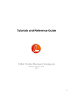

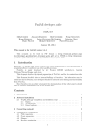
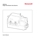


![[U4.72.04] Opérateur CREA_CHAMP](http://vs1.manualzilla.com/store/data/006355027_1-feb0d118e0073065afa5acc9e74a2674-150x150.png)
![[U4.03.01] Titre et sous-titre d`un concept produit](http://vs1.manualzilla.com/store/data/006368269_1-8512601d28a11662e034fcf06e531458-150x150.png)
![[U4.61.21] Macro commande MACRO_MATR_ASSE](http://vs1.manualzilla.com/store/data/006350914_1-184ee2431ef58659d0df91ee081aa278-150x150.png)