1
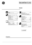
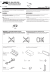
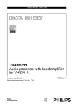
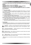
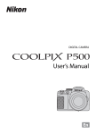
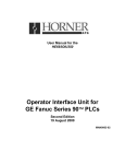
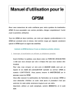
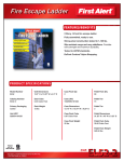
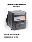
Chapter
51
3
Maintenance
m
GFK-0122
Introduction
This chapter presents
Logic Controller. The
failure should occur,
minimum downtime.
hardware or software
assemblies (modules),
a basic guide to troubleshooting procedures for the Series Five Programmable
Series Five PLC is designed to provide many years of trouble free operation. If a
it can usually be quickly isolated and the defective assembly replaced with
It is important to quickly identify the source of the problem, and whether it is
related. The maintenance concept for the Series Five PLC is to replace failed
rather than individual components.
Troubleshooting Aids
The CPU has many internal bits and diagnostic registers which can be used in the user program or
external CCM compatible computer to implement a custom diagnostic package. Many of these internal
bits and registers are used by Logicmaster 5 to report errors. Most typical problems are isolated through
interpretation of the LEDs on individual modules or through error codes or messages on the programming device’s screen These troubleshooting aids help diagnose not only the Series Five PLC, but also
the total control system.
The main diagnostic tool is the programming
device, which can be a
Workmaster II portable computer, a Workmaster, or Cimstar I industrial computer, or an IBM PC, XT,
AT, PS/2 or compatible personal computer with Logicmaster 5 software.
Many hardware related faults can be attributed to incorrect switch settings, loose cables or screw
connections - all major faults can be corrected by replacing modules. There are usually no special tools
required other than a screwdriver and a voltmeter.
Series Five Diagnostic Aids
The diagnostic features of the Series Five PLC provide the user with a powerful, easy to use
troubleshooting tool. These diagnostic features not only tell you that an error has occurred, they also
lead you to the location of the problem. These diagnostic features are: status indicators on the CPU and
all other modules, special purpose internal coils that turn on to reflect error conditions, reserved registers
that indicate an error code number or other tiormative
information, the CPU ERROR FLAGS display
in the Scratch Pad screen in Logicmaster 5, and the error display in the OIU. Logicmaster 5 provides
the tools for displaying and interpreting error messages and leading you to the cause of the problem.
When a failure occurs, a bit or bits will be set in the CPU ERROR FLAGS line at the bottom of the
Scratch Pad display, and an error message will be displayed. In most cases, the cause of the problem is
indicated. If additional information about the problem is needed, by accessing a HELP screen, you are
directed to an explanation of the bit or bits that are set, i.e., the nature of the error. You can then display
the reference table for the special contacts (Il-000 to 11-5 12) to see which of the contacts has been set to
a logic 1 or access the register display and look at registers 4078,4079, and 4080. These registers will
display an error code number. Then refer to table 5.2 for error code definition and the action to take to
clear the problem.
The flow chart on the following page shows the recommended
Five PLC.
troubleshooting
procedure for the Series
52m
Maintenance
GFK-0122
a42408
)
Turn power on to power supply.
Connect power supply source voltage wiring.
Ensure that jumper is configured correctly
for 115 or 230 VAC - for AC supplies.
Replace power supply.
Read error message in LM5 Scratch Pad.
See Table 5.1 below for messages and
action to clear error.
Look at Registers 4078,4079, and 4080 in
Hexadecimal display mode. Error codes are
read from these registers. If contents
are non-zero, refer to TaMe 5.4 for error code
definition.
If not enough information to solve problem refer
to tabie 5.2 for definition of special bits.
mcorrect cause of error by
taking corrective action as
listed under “ACTION TO CLEAR
I ERROR” in Table 5.4.
Figure 5-l. Recommended Troubleshooting Sequence Flow Chart
53m
Maintenance
GFK-0122
Table 5-l. Scratch Pad Error Messages and Corrective Action
~~
Comxtive
Scratch Pad Error Message
Compilation Error
CPU Battery Low
Duplicate I/O Address Error
I/O Address Range Error
I/O Bus Error
I/O Cotig
Changed
I/O Enor
I/O Module Removed
I/O Parity Error
Memory Battery low
NO CPU BATTERY
NO Battery in memory
cartridge
No Memory Cartridge Error
Program Error
Program Parity Error
Watchdog Timer Timed Out
Action
Store program to CPU again
Replace CPU battery within one week
Reassign addresses and do a STORE TO CPU.
Correct user logic and store program again.
Cycle from STOP to RUN, or reset CPU with reset switch, or Recycle power, or
replace base unit or device on bus.
Key-in NEW CONFIG or OLD CONFIG command from LM5 or edit I/O map
and do a STORE TO CPU, or return to previous I/O configuration.
See Table 5.2 in this chapter for further information.
With power off, replace module. Or edit I/O map and STORE TO CPU
Cycle f!rom STOP to RUN, or reset CPU with reset switch, or cycle power.
Replace base unit, or device on I/O bus.
Replace memory cartridge battery within one week.
Connect or instaIl back-up battery in CPU.
Install battery in memory cartridge.
With power off - install memory cartridge.
Check user program, correct error and store program again
Store program again. Cycle power.
Check user logic or increase Watchdog Timer preset value.
Table 5-2. Special Purpose Contact (Bit) Definition
^
-
Reference
11-0033
11-0034
11-0035
11-0036
11-0037
11-0038
11-0039
Error
Critical System Error
Non-Critical System Error
Diagnostic Error
Battery Not Normal
Memory Error
I/O Error
Communications Error
I/O ConQuration Error
11-0042
11-0043
11-0044
11-0045
11-0065
Watchdog Timeout
Internal Program Error
Internal Math Error
Smart Module Comm. Error
I/O Retry Parity Status
11-0066
Non-Critical Rack
DdhitiOIk
1=
1=
1=
1=
l=
l=
l=
error, CPU goes to STOP mode.
error, CPU remains in RUN mode.
error detected
CPU or memory cartridge battery voltage low.
latches if a memory cartridge error occurs.
latches if I/O bus error is detected
Turned ON by a CPU/CCM error. Next successful
communications will turn it off.
lo?=error detected, I/O configuration has changed since last
power-up.
1 = Watchdog timer has timed out.
1 =Error
l=Error
1 =Error
1 = Parity error after specified number of retries
0 = OK, no parity error detected
1 = Non-critical rack 0 = Critical rack (that reported parity error
setting 11-0065)
54m
Maintenance
GFK-0122
CPU Status Indicator Definitions
The flow chart for basic troubleshooting procedures indicates that observation of system indicator lights
is a good starting point to use for troubleshooting. The following table defines the LED status indicators
’
located on the CPU. .
Table 5-3. CPU Status Indicator Definitions
LED
DESCRIPTION
COLOR
PWR
GREEN
ON - Power is applied to the CPU and the +5 Vdc operating voltage is within specified
tolerance.
OFF - AC or dc input power source is missing or the +5 Vdc operating voltage is not
withk specified tolerance.
RUN
GREEN
ON CPUisintheRUNmode.
OFF - CPU operation is halted,
CPU
RED
ON - A malfunction exists in the CPU or the watchdog timer has timed out.
OFF - CPU is operating normally and the watchdog timer has not timed out.
DIAG
RED
ON - CPU has detected an internal fault that causes the CPU to halt its scanning
Operation.
OFF - Operation normal, no faults detect&
BA’IT
AMBER
ON - A memory backup battery voltage is low or has failed. Can be eith& in the CPU or
memory cartridge battery.
OFF - Both backup batteries operating normally.
MEM
AMBER
ON - A program memory error has been detected
OFF - All memory operating without error.
I/O
AMBER
ON - An I/O error has been detected.
OFF - No I/O errors have been detected.
COMM
AMBER
ON - A communications error has been detected
OFF - Communications operating without error.
For detailed exror definitions, refer to the Logicmaster 5 Scratch Pad Display and Register tables (R4078,4079,
4080).
Maintenance
55
m
GFK-0122
Error Definition and Action Required
The LEDs on the CPU are a good troubleshooting
aid. When combined with the capabilities of the
programmer with Logicmaster 5 or when using the Series Five Operator Interface Unit, you can quickly
troubleshoot the majority of system errors that may occur. The following table lists the errors that may
be detected by the CPU. Two tables are found in this section - the first lists the error codes, definitions
and corrective actions when using Logicmaster 5 software, and the second table lists error codes and
messages, cause of error, and corrective actions when using the Operator Interface Unit. The information in the tables is as follows:
ERROR CODE/MESSAGE:
CAUSE OF ERROR:
ACTION TO CLEAR ERROR:
Error code number and message (message with OIU)
Action or problem that caused the error.
Action required to clear the error.
Table 514. Error Code Definitions - Logicmaster 5
.
Error
Code
Action
Cause of Error
E003
Scan time exceeds Preset time of Watchdog timer
EOO4
E041
E042
E043
CPU memory parity error detected
Voltage of CPU back-up battery too low.
No back-up battery in CPU.
Voltage of back-up battery installed in memory cartridge
too low.
*
E044
El01
No battery or dead battery in memory cartridge.
No memory cartridge in CPU.
El02
Memory cartridge contains only CPU parameters.
El03
Memory cartridge contains only registers.
El50
El51
El52
Register reference is greater than maximum register size.
Memory parity error in user logic.
\\
Rung too complex to execute.
E201
E202
E222
Terminal block removed from I/O module.
I/O con@uration change since last power-up, or I/O
module removed Tom slot.
Blown fuse or no fuse in an output module. FU indicator
on output module will also be 0111,
Voltage of external 24 V dc power to output module too
low.
No power applied to Series Three PLC’s I/O base unit
connected through a Series Three PLC I/O Interface
module.
A problem exists in the Series Three PLC’s I/O system.
E250
Error on I/O bus or device connected to I/O bus.
E203
E204
E221
to Clear Error
Check user logic or increase watchdog
timer preset
Cycle power. Store program again
Replace CPU battery within one week.
Install back-up battery in CPU.
Replace battery in memory cartridge within
one week Contents of memory cartridge
must be copied before you change the
batteryordatawillbelost.
Install battery in memory cartridge.
With power off, install memory cartridge
in CPU.
With power off, insert user program MC in
the CPU.
With power off, insert user program MC in
the CPU.
Change register reference.
Store program again
Change user logic program to have fewer
stack levels.
With power off, install terminal block.
With power off, install I/O module in
correct slot
With power off, remove output module
and install new fuse, or replace module.
Adjust voltage of external power supply.
Apply power to the Series Three PLC’s
I/O base unit.
Troubleshoot the Series Three PLC’s I/O
system and replace defective module(s).
Recycle power, or push CPU reset
pushbutton, or replace base unit or
device.
.
56I
Maintenance
Table 5-4. Error Code Definitions - Logicmaster 5 - Continued
Error
Code
Cause of Error
E251
I/O bus parity error, noise.
E252
Current I/O configuration is different than the one stored
in the memory cartridge.
E261
E262
E350
E351
E352
E353
E354
E4xx
I/O address duplicated when assigned manually.
I/O address in user logic exceeds valid address range.
Specified target address is not an intelligent module.
Invalid ID specified for intelligent module (target).
Syntax error present in command parameters
Timeout when communicating with target.
No infomation obtained from target device
Translated program error.
Action to Clear Error
Cycle power. Replace base unit, or device
on I/O bus.
Key-in NEW CONFIG command or OLD
CONFIG command from LM5 or edit I/O
map and do a STORE TO CPU.
Reassign addresses with no duplication.
Correct user logic.
Specify correct target address.
Reassign correct target ID.
Use correct syntax@uameters.
Check target source and all interconnects.
Verify target information
Check and reload program.
Table 54. Error Code Definitions - Operator Interface Unit
Error Message
EO03 S/W TIMEOUT
E041 CPU BATTERY LOW
E042 NO CPU BATI’ERY
E043 CPU MC BATTERY
LOW
EO44 NO MC BATT
El01 NO CPU MC
Cause of Error
Action to Clear Error
CPU scan time was greater than software Set longer software watchdog (sub-menu
54) or change ladder logic.
watchdog timer.
Replace
CPU battery,
Cat.
No.
Low voltage on CPU back-up battery.
IC655ACC550
Install or reconnect CPU battery.
Missing or disconnected CPU battery.
Low voltage on CMOS RAM memory Copy program to another memory carbattery
tridge
and
replace
cartridge battery.
(IC655ACC549).
Missing CMOS RAM memory cartridge Install battery in memory cartridge.
battery.
Attempt to access CPU MC when it is not Insert memory cartridge into CPU.
install&
El02 MC HOLDS SYS DATA
Attempt to run CPU with MC installed Replace with a program memory carthat contains only system parameter tridge.
El03 MC HOLDS REG DATA
Attempt to run CPU with a memory car- Replace with a program memory cartridge.
tridge that contains register data
Copy operation to CPU MC in Menu 7 Reconfigure the jumper in memory carfailed because cartridge is write protect- tridge to the write enable position. If
problem still exists - replace memory
ed.
cartridge.
El04 WRIIE FAILED
El50 REG REF TOO LARGE
El51 BAD COMMAND
El52 PROG STACK
OVERFLOW
Register reference larger than maximum Change register reference.
register size.
Parity check detects error in program Rewrite the invalid code to correct the
logic.
stored on the CPU memory cartridge.
Change logic to have fewer stack levels.
Rung too complex to execute
57m
Maintenance
GFK-0122
Table 5-S. Error Code Definitions - Operator Interface Unit - Continued
Error Message
E2XX DIAG ERROR MENU
42
Cause of Error
Action to Clear Error
4n I/O diagnostic error has been reported
to the CPU.
Jse sub-menu 41 or visual inspection to
determine the type of error, and take corrective action. Error can be one or more
of errors E201 to E262.
E201 MISSING TERM BLOCK
~~)se or missing terminal block on I/O he sub-menu 41 or visual inspection to
find module location. With power off module.
tighten terminal block or install new terminal block on module.
E202 MISSING I/O MODULE
/O module loose or missing since last Jse sub-menu 41 or visual inspection to
power cycle.
determine module type and location of
missing module. With power off - install module and secure to base unit.
he sub-menu 41 or visually find module
?use blown on an output module.
type and location. With power off replace fuse or module.
3xtemal24 Vdc power supply is too low Sdjust voltage, correct fault or replace
or has failed.
supply*
I/a
l/a
E203 I/O MDL FUSE BLOWN
E204 LOW VOLTAGE EXT PS
E208 ILLEGAL MODULE
CODE
E221 NO SERIES 3 I/O PS
E222 S3 I/O ABNORMAL OP
E226 PS OVERLOAD
E250 I/o CHAIN
E251 I/O BUS PARITY
E252 NEW I/O CONFIG/
E261 I/O ADDR CONFLICT
E262 I/O OUT OF RANGE
E311 COMM ERROR 1
E312 COMM ERROR 2
E313 COMM ERROR 3
E316 COMM ERROR 6
?ower supply failed or power @offon Se- hn on power, repair or replace power
supply in Series Tbree base unit.
ries Three I/O base unit.
Series Three I/O module or modules fhc- ktermine which module is defective and
_
replace.
tioning abnormally.
2PU has detected that I/O loading in a Jse high capacity power supply or adjust
base unit exceeds the power supply ca- I/O module arrangement.
pacity.
?aulty link in the I/O chain.
Zheck I/O expander cables, Local I/O Interface module.
Parity error on I/O bus due to electrical Cycle power, if CPU won’t enter RUN
mode, replace base unit or device on
noise or other type of interference.
bus .
Current I/O configuration is different than Use submenu 45 to select the former or
the one stored in CPU memory cartridge. the new config, or change I/O config to
its previous configuration.
Attempt made to force a module to an Use sub-Menu 46 to change one of the
address already assigned to another modules address to a avoid duplication.
module.
&tempt made to force a module address Use sub-menu 46 to re-enter a valid address.
to an invalid address.
A non-existent operation code was includ- Key-in CLR to retry the communications.
ed during a CCM communications session.
A non-existent operation code included Key-in CLR to retry the communications.
during communications with a program
mer.
A non-existent address was included dur Key-in CLR to retry the communications.
ing communications with a programmer
A non-existent mode was included during Key-in CLR to retry the communications.
communications with a programmer.
580
Maintenance
GFlLO12
Table 5-S. Error Code Definitions - Operator Interface Unit - Continued
Error Message
Cause of Error
Action
to Clear Error
E320 OIU-CPU TOUT
Communications time out between CPU Cycle power. If problem persists - replace
and OIU.
faulty unit (OIU or CPU).
E321 OIU-CPU COMM
No reply or NAK from the CPU to an Check link between the OIU and the CPU.
OIU ENQ.
Cycle power. If problem persists - replace the CPU.
E350 MODULE ADDR
A base unit and slot address has been Reassign the intelligent module address
specified that does not contain an intelli- either in the user logic program or
gent module - when attempting commu- through sub-menu 47 on the OIU.
nications between intelligent modules or
between OIU to intelligent modules.
E351 MODULE ID
Invalid communications ID number speci- Reassign the correct intelligent module ID
fied for an intelligent module during in user logic program.
communications
between intelligent
modules.
E352 BGND SETTING
Syntax error occurred during background Key-in CLR and retry communications.
communications.
E353 BGND TOUT
Communications time out during commu- Key-in CLR and retry communications.
nications session between two intelligent
modules.
E360 TIME OUT
During communications between a per- Press the CLR key and retry communicasonal computer and OIU, the personal tions.
computer did not respond to an enquiry.
E361 COMM ERROR
Communications problems between CPU Retry communications,‘check cable conand OIU.
nections, check OIU mounting to CPU.
E4=
Mode keyswitch turned to RUN with no Download program from computer to
program in the CPU memory cartridge.
CPU, or insert memory with program.
NO PROGRAM
E501 BAD ENTRY
Invalid key sequence attempted before Rekey correct sequence of keys.
ElNT, PREV, or NEXT keys.
E504 BAD REF/VAL
Reference number or value entered is out Re-enter correct value.
of range.
E520 BAD OP-RUN
Attempt made to perform an operation
which is illegal when the CPU is in the
RUN mode.
Attempt made to perform an operation
which is illegal when the CPU is in the
RUN w/OUTPUTS DISABLED mode.
Attempt made to perform an operation
which is illegal when the CPU is in the
STOP mode.
CPU mode keyswitch not in the OIU position.
E521 BAD OP-RDIS
E524 BAD OP-STOP
Es25 KEYSWITCH
E526 OIU OFFLINE
E540 CPU LOCKED
E541 WRONG PWORD
Change CPU mode to allow the operation.
Change CPU mode to allow the operation.
Change CPU mode to allow the operation.
Turn key to OIU position.
Attempt to perform an operation while Use sub-menu 64 to put OIU on-line.
OIU is off-line.
Attempt to perform a password protected Logon to the locked CPU with sub-menu
operation without logging-on to the 81, and repeat operation.
locked CPU.
Wrong password entered for the memory Re-enter correct password for the memory
cartridge in the OIU.
cartridge in the OIU.
59w
Maintenance
GFK-0122
Table 5-S. Error Code Definitions - Operator Interface Unit - Continued
Error Message
%Ol MEMORY FULL
Cause of Error
, Attempt to program instruction too large Copy program onto a larger memory car-
for available memory.
E603 DATA MISSING
E610 BAD I/O TYPE
Action to Clear Error
tridge and continue entering program.
While searching for data in registers Press CLR and respetify data value or
(sub-menu 33), no data that was speci- register range.
fied was found in the specified register
range.
Attempt made to read/write an intelligent Retry operation - specify correct base
I/O module through sub-menu 47; how- unit/slot for the intelligent module.
ever, location specified was for a conventional I/O module.
E611 BAD COMMS ID
Attempt made to communicate with a Set correct CCM ID.
CCM station ID that does not exist.
E620 OUT OF MEM
Copying operation incomplete because of Change to larger memory cartridge, or
insufficient memory remaining on mem- restructure program.
ory cartridge.
(1) Blank check with sub-menu 74 has Clear the memory cartridge using
detected data on the OIU memory car- sub-menu 75 or use another memory cartridge.
tridge.
(2) Attempt to copy to or erase a write Change jumper in memory cartridge to
unprotected position.
protected RAM or EEPROM cartridge.
E621 MC NOT BLANK
(3)Attempt to copy to UVEPROM car- Erase contents of UVEPROM cartridge
with an ultra violet lamp, or use another
tridge that already contains data.
UVEPROM cartridge. b
E622 NO MC IN OIU
Attempt ma& to transfer data to or from a Insert an appropriate meniory cartridge inmemory cartridge in the OIU with no to the OIU.
memory cartridge installed in the OIU.
E623 SYSTEM MC
Attempt made to transfer user logic fkom Remove memory cartridge Tom OIU and
OIU memory cartridge to CPU memory insert one that contains user logic.
cartridge when OTU memory cartridge
contains other than user logic.
E624 REGS ONLY
Attempt made to transfer user logic from Remove memory cartridge f!rom OIU and
OIU memory cartridge to CPU memory insert one that contains user logic, or
cartridge when OIU memory cartridge select register option from sub-menu 72.
contains register daW
E625 PROG ONLY
Attempt made to transfer registers from Remove memory cartridge Tom OIU and
the OIU memory cartridge to the CPU insert one that contains register data, or
select program option from sub-menu
memory cartridge when the OIU meme
72 .
ry cartridge contains user logic.
E626 EPROM MC
Attempt ma& to copy data onto an Install a RAM or EEPROM cartridge in
EPROM memory cartridge installed in the CPU, or insert the EPROM memory
cartridge in the OIU to copy data.
the CPU.
E627 BAD WRITE
RAM or EEPROM cartridge in OIU is Reconfigure the memory cartridge jumper
write protected, or UVEPROM cartridge to the write enable position.
in OIU has not been eras& or CPU has
detected a mismatch of data while copying data with sub-menu 71 or 72.
E640 MISCOMPARE
Data mismatch detected while performing Clear the OIU or CPU memory cartridge,
as applicable, and retry the copy operaa verification in sub-menu 73 or 79.
tion.
540
Maintenance
GFlC-0122
Table 5-5. Error Code Definitions - Operator Interface Unit - Continued
Error
Message
Cause of Error
Action
.
to Clear Error
E641 VOLUME LEVEL
Cassette recorder volume level set too Readjust volume level and repeat operahigh or too low when in sub-menu 77, tion.
78, or 79.
E642 CHKSUM ERROR
Checksum error when copying between Repeat operation, after clearing the OIU
cassette tape and OIU, or external com- memory cartridge, or other medium
puter and OIU.
where appropriate.
E650 MACHINE CODE
CPU detected an unknown op code value Press CLR key. If problem persists,
during execution of a program instruc- reload program or provide more protection.
tion from electrical noise or other interference for CPU.
E651 SYSTEM ROM
Checksum error exists in OIU ROM.
Press CLR key and repeat operation. If
problem persists - replace the OIU.
E652 SYSTEM RAM
Checksum error exists in OIU RAM
Press CLR key and repeat operation.
problem persists - replace the OIU.
E653 MC BATI’ LOW
Battery voltage in OIU memory cartridge Replace battery in memory cartridge, or
low.
use another memory cartridge.
If
General I/O Troubleshooting Procedures
I/O troubleshooting procedures depend upon knowledge of the logic program installed for your application. The following procedures are general in nature, and should be adjusted to fit your specific
application. The following steps assume that the CPU is in the RUN mode - operating with outputs
enabled.
1. If the Series Five PLC has stopped with some of the outputs energized, locate the signal (timer, coil,
input, etc.,) that should cause the next operation to happen.
The state of that signal can be
monitored by Logicmaster 5.
2 . If the signal is an input, compare the state of the input monitored with the programmer, with the
state of the LED for that input on the input module. If they are different, replace the module.
Do not install or remove any I/O module when power is applied to the base unit. Failure to
adhere to this warning could cause a module to be damaged.
Voltages from user devices may be present on a module’s screw terminals, though power to
a base unit is turned off. Care must be taken any time that you are handling the module’s
terminal board or any wires connected to it.
3 . If an input state and the applicable LED on the input module agree, compare the LED status with
the actual input device (limit switch, pushbutton, etc.). If they are different, measure the voltage at
the input module terminals. Refer to the Series Five Programmable Controller II0 Specifications
Manual, GFK-0123, for specific module information. If the measured voltage indicates a faulty I/O
device - replace it, or the field wiring, or its power source. If this does not solve the problem,
replace the input module.
Maintenance
5-11
GFK-0122
4 . If the signal is a coil wired to a field device, compare its status to the LED on the applicable output
module. Lf they are different, check the power source to ensure that an excitation voltage is
available. If field power to the device is not present, check the power source and its wiring. If the
correct field power source is available, but the status is wrong at the output module - replace the
output module.
5.
If the signal is a coil, and either there is no output module or the output is the same as the coil state,
examine the logic driving the output using the progr amming device, and a hard copy of your
Working from right towards left, locate the first contact that is not passing power
program.
available to it from the conditional logic at its immediate left.
Troubleshoot that signal using the procedures in steps 121 and m if the signal is an input, or steps
and
if the signal is a coil.
q
q
6 . If the signal is a timer that has stopped at a non-zero value below its preset value, replace the CPU
module.
7 . If the signal is the control over a counter, examine the logic that is controlling the reset first - then
the count signal.
Follow steps a
through m.
Replacing Components
The following procedures
PLC system.
provide information on replacement of various components
*
of a Series Five
Replacing a Power Supply
1. Turn off AC or DC power, as applicable, to the supply.
2. Disconnect
field wiring from the power supply terminal block.
a42666
I
*
0
RUN
RUN
RUN
C (SIGNAL GROUND)
0
18
C (SlGNAL GROUND)
I@
C (SIGNAL GROUND)
0
t0
I0
i
G (CHASSIS GROUND)
1@
:‘G (CHASSIS GROUND)
AC - HOT
18
I0
AC - NEUTRAL
E?
0
0
115 VAC
JUMPER
CONNECTED
Figure 52.
AC-HOT
24 VDC - POS
AC - NEUTRAL
24 VDC - NEG
NO CONNECTION
230 VAC
JUMPER
NO
IC655PWR500
IC655PWR501
G (CHASSIS GROUND)
NO CONNECTION
1
IC655PWR514
Power Supply Terminal Block Connections
s-12
Maintenance
GFK-0122
3 . Remove the power supply by loosening the two captive screw fasteners that are holding the supply
in place.
4 . Install the new power supply by placing it over the connector on the backplane and pushing down
on the module until it is f’lrmly seated.
5 . Reconnect field wiring to the power supply terminal block, and verify that the jumper for 115 or
230 V ac is properly configured if the supply is an AC supply.
6 . Apply power to the system and check for proper system operation.
Replacing a CPU Module
1. Place the CPU mode switch in the STOP position.
power supply.
Turn off AC or DC power, as applicable, to the
2 . Disconnect any cables that may be attached to the CPU. Remove the memory cartridge installed in
the CPU. Write down the DIP switch settings to ensure that the settings on the new CPU are the
same.
3 . Remove the CPU from its slot by loosening
from its backplane connectors.
the two captive screws and pulling the module away
4 . Install the new CPU module, and tighten the two captive screws.
5 . Ensure that the DIP switch settings are correct for your operation and verify that the CPU backup
battery is properly installed .
6 Reconnect
l
7.
any cables, you may have removed,
to the CCM port connectors
on the CPU.
Apply power and verify system operation.
Replacing a Memory Cartridge
1. Place the CPU mode switch in the STOP position.
power supply.
Turn off AC or DC power, as applicable, to the
2 . Open the top hinged door on the front of the CPU to gain access to the memory cartridge.
3 . Remove the memory cartridge by grasping the top of the plastic strip at the point marked “PULL”,
then pull it towards you. The cartridge will slide out of its slot.
Do not remove or insert a memory cartridge with power on. Handle RAM memory
cartridges with care, since excess charges of static electricity could damage the memory
devices in the cartridge.
4 . Install the new memory cartridge by orienting the cartridge so that the word “PULL” is towards the
top of the CPU, then slide the cartridge carefully into the guides in the slot until it firmly plugs into
the connector at the back of the slot.
5 . Turn on AC or DC power to the base unit and verify proper system operation.
Maintenance
5-13
GFK0122
Replacing a Memory Cartridge Backup Battery
1. Before replacing a memory cartridge battery, the memory contents
memory in the cartridge will be lost when a battery is changed.
should be saved, since the
2 . Remove the memory cartridge as described previously.
3 . Remove the phillips head screw that attaches the top cover to the case containing
the memory
cartridge.
a42417
Figure 5-3. Memory Cartridge Battery Location
4 . You do not have to remove the circuit board from the case
battery is mounted on the circuit board and can be removed
of the battery until it is completely free of the socket. It is
or a non-conductive tool for pulling the battery out of the
to remove and replace the battery. The
by very gently pulling up on the bottom
recommended that you use your fingers
socket.
Be very careful when removing the battery from its mounting holes to ensure that the
circuit board is not damaged. Be careful not to short runs or components on the circuit
board when using a screwdriver.
5 . Notice that the holes into which the battery is inserted are offset to one side, this ensures that proper
battery polarity is observed. Insert the new battery into the mounting holes by placing it over the
holes, then gently pushing down on the battery case until it is firmly seated in place. Do not bend
the two leads on the battery.
6 . Replace the cover and replace and tighten the screw. Before turning on power, ensure that the CPU
mode keyswitch
is in the STOP position.
5-14
Maintenance
GFK-0122
7. Before turning power on, reinstall the memory cartridge in the CPU. The memory will be blank or
have random data in it - you will need to execute an INTI’ CPU (Initialize CPU) function from the
Scratch Pad screen. Reapply power to the system and check the system for proper operation.
’ Replacing a CPU Backup Battery
1 . Ensure that power has been applied to the system at least one minute before changing the battery.
Remove AC or DC power, as applicable, from the CPU base unit.
2 . Access the battery by opening the large hinged door on the front of the CPU module.
mounted on the inside of the door.
The battery is
3 . Remove the battery connector from the socket in the CPU by grasping it and pulling it straight out
until it is free of the socket. To ensure that the wires in the battery do not pull out of the connector,
it may be necessary to use a pair of needle nose pliers to grasp and remove the connector.
4 . Pull the battery out of the mounting
clips on the door.
5 . Replacement batteries come with the connector prewired to the battery. To install the new battery,
insert it into the mounting clips, and push the battery connector firmly into the socket on the CPU
until it is securely in place.
6 . Turn on power to the base unit.
7 . Reinitialize the CPU. This will cause the CPU system parameters to be reset to their default
conditions, and will clear Logicmaster 5 memory and Series Five CPU memory.
8 . Verify that system operation
is correct.
a424 15
L
INSERT
BATIERY
CONNECTOR
INTO
BOARD
CONNECTOR
-
0
00
00
00
00
00
00
00
00
00
00
00
00
00
-0
r
Figure $4.
CPU Battery Mounting and Connection
545
Maintenance
GFK-0122
Replacing I/O Modules
1. Turn off AC or DC power, as applicable, to the base unit in which the I/O module to be replaced is
contained, and Tom the I/O system.
2 . Remove the faceplate from the module to be replaced. There is no need to remove field wiring from
the teminal block, since the block is removable. Disconnect the removable terminal block from the
module by removing
board assembly.
the two captive screws holding the terminal block to the module’s
circuit
a42416
Aim
am
sm
49
am
*m
sm
*m
smmm
am sm
7m am
am 4m
rmlnm
om rm
7m sm
om 4m
w
om
7m
w
8m
om
7m
n
Figure 5-5. Removal of Terminal Block From Module
3 . Loosen the two captive screws holding the module in place, and remove the module from its slot by
pulling it towards you.
4 . Install the new module in the slot by lining it up with the backplane connector for its slot and firmly
pushing the module into the connectors until it is securely seated, then tighten the two captive
screws.
5 . Place the terminal block over the edge connector on the circuit board and fimnly push down.
Tighten the two screws on the terminal block, then replace the plastic faceplate cover.
6 . Reapply power to the base unit and to the field devices, and verify that the system is operating
properly.
-
546
Maintenance
GFK-0122
A list of parts for the Series Five PLC is provided in table 5-6. It is recommended that a spare parts kit
be available so that your Series Five PLC system can be returned to service with a minimum amount of
downtime if a problem does occur.
Table 5-6. Series Five PLC Parts List
Catalog Number
Description of Item
Base Units/Power Supplies/Cables/Miscellaneous
IC655CHS506
IC655CHS508
IC655CBL500
IC655CBL501
IC655CBL502
IC655CBL503
IC655CBL504
IC655CBL505
IC655CBL540
IC655CBL541
IC655PWR500
IC655PWR501
IC655PWFW4
IC655CHS590
IC655ACC551
IC655ACC552
IC655ACC553
IC655ACC554
Base Unit, with 6 I/O slots
Base Unit, with 8 I/O slots
I/O Expander Cable, 1 feet (.5 m)
I/O Expander Cable, 3 feet (1.0 m)
I/O Expander Cable, 15 feet (5 meters)
I/O Expander Cable, 30 feet (10 meters)
I/O Expander Cable, 80 feet (25 meters)
I/O Expander Cable, 160 feet (50 meters)
OIU to CPU Cable, 5 feet (1.5 m)
OIU to CPU Cable, 10 feet (3.0 m)
AC Power Supply, 115/230 V ac Input, 6 amps (maximum)
AC Power Supply, 115/230 V ac Input, 12 amps (maximum)
DC Power Supply, 24 V dc Input, 6 amps (maximum)
I/O Rack Terminator Plug
Oversized Faceplate
Filler Module
19 inch Rack Mounting Bracket
OIU Mounting Bracket
CPU - Batteries - Memory Cartridges - Interface and Special Modules
IC655CPU500
IC655ACC549
IC655ACC550
IC655MEM501
IC655MEM503
IC655MEM5 12
IC655MEM513
IC655MEM521
IC655APU500
IC655APU510
IC655APU521
IC655BEM500
IC655BEM5 10
IC655BEM530
IC655CBL530
IC655CCM500
CPU module
Battery, memory cartridge
Battery, CPU
4IQ24K RAM memory with battery back-up
16K RAM memory with battery back-up
8IQ24K EPROM memory (W erasable)
16K EPROM memory (W erasable)
4K EEPROM memory (electrically erasable)
ASCII/BASIC Module
High Speed Counter
Axis Positioning Module ‘&
Local I/O Interface module
Genius Bus Controller module
Series Three I/O Interface module
Series Five to Series Three Cable, 3 feet (lm)
CCM Communications Module
Input Modules
IC655ALG5 16
IC655MDLSOl
IC655MDL502
IC655MDL503
IC655MDL5 11
IC655MDL5 12
IC655MDL524
IC655MDL525
IC655MDL526
IC655MDL527
IC655MDL533
Analog Input, 1 to 5V, 0 to +lOV, -10 to +lOV, 4 to 20 mA, 8 Channels
12/24 V & Input, Negative Logic, 16 Circuits
12/24 V dc Input, Negative Logic, 32 Circuits
24 V dc Input, Positive/Negative Logic, 64 Circuits
24/48 V ac/dc, Isolated Input, Positive Logic, 16 Circuits
12124 V ac/dc Input, Positive Logic, 32 Circuits
Input Simulator, 16 or 32 Circuits (switchable)
115/230 V ac Input, 16 Circuits
115 V ac Input, 32 Circuits
115/230 V ac, Isolated Input, 16 Circuits
5/12 V dc ‘ITL Input, Positive/Negative ogic, 64 Circuits
Maintenance
GFK-0122
Table S-6. Series Five PLC Parts List - Continued
Catalog Number
Description of Item
Output Modules
IC655ALG566
IC655ALG567
IC655MDL55 1
IC655MDL552
IC655MDL555
IC655MJlDL556
IC655MDL575
IC655MDL576
IC655MDL577
IC655MDL580
IC655MDL58 1
IC655MDL586
IC655MDL593
Analog Output, 0 to +lOV, 4 to 20 ti
2 Channels
Analog Output, -10 to +lOV, 2 Channels
12/24 V dc Output, Negative Logic, 16 Circuits
12/24 V dc Output, Negative Logic, 32 Circuits
12/24 V dc Output, Positive Logic, 16 Circuits
12/24 V dc Output, Positive Logic, 32 Circuits
115/230 V ac Output, 16 Circuits
115/230 V ac Isolated Output, 16 Circuits
115/230 V ac Output, 32 Circuits
Relay Output, 16 Circuits
Relay Output, 32 Circuits
Isolated Relay Output, 16 Circuits
5/12 V dc TIL Output, Positive Logic, 64 Circuits
List of Fuses
The following
table contains a list of fuses that are used in Series Five Output modules.
Table 5-7. Fuses Used in Output Modules
Module Name
24 V dc Out, Neg Logic
24 V dc Out, Neg Logic
24 V dc Out, Pos Logic
24 V dc Out, Pos Logic
115/230 v ac out
115/230 v ac Is01 out
115/230 v ac Out
Relay Out
Catalog
Number
IC655MDL55 1
IC655MDL552
IC655MDL555
IC655MDL556
IC655MDI.575
IC655MDL576
IC655MDL577
IC655MIX.580
slow/Fast
Blow
Qts On
Rating
Module
User
Replaceable
8=P
3amP
8amP
3 amp
8aP
3amP
5amP
8amP
Fast
Fast
Fast
Fast
Fast
Fast
Fast
Fast
4
4
4
4
2
16
4
4
Yes
Yes
Yes
Yes
Yes
No
No
Yes
current
MF51SH8
MF51sH3
MF51SHS
MF51sH3
MF51SH8
MC3
MC5
MFSlSH8
* MF5lSH3, MF51SH8 - 20 mm x 5.2 mm - cartridge type
MC3, MC5 - 9 mm x 2.7 mm - pigtail type, soldered-in place
548
Maintenance
GFK-0122
Accessory Kit for the Series Five PLC
Anaccessory kit (IC655ACC520) is available to support the Series Five PLC.
This kit contains many of
the most commonly used components eat may get damaged or lost during normal operation, such as
fuses, screws, terminal covets, etc. Rather than attempting to order all of these parts separately, this kit
provides a convenient means of ordering and storing these parts. Each kit should be sufficient to support
several PLCs, depending on their I/O count. Items included in the kit are listed below.
Table 54%.Accessory Kit
Item
CPU keys
CPU door, with CCM hinged door and OIU port cover
I/O wiring labels for inside faceplate, 16/32 pt
Plastic bead chain (I/O faceplate to module)
Screws/washers, all sizes .
Dust covers for I/O bus port connector
Dust covers for I/O expansion port connector
Fuses, fast blow - 2A, 3A,3.15A, 5A, 8A
Faceplate for I/O module
Faceplate for power supply
Module access side cover
*
Jumper bar for power supply
Jumper for register size configuration
Keying inserts for terminal block, 16 and 32 point
Memory cartridge labels (CMOS RAM, EPROM, EEPROM)
Quantity
in Kit
2 sets (2 keys per set)
1
50 of each type
20
10of each
4
2
5 of each
3
1
3
2
2
10 of each
36 labels, etich type
.
549
Maintenance
GFK-0122
Figure 5.6 is an illustration of the accessory kit location guide, GFJ-011, which is packed with each
accessory kit. This guide shows the location and lists the quantity of each item in the kit.
GE Fanuc
GFJ-011
SERIESFIVE ACCESSORY
.KK
lc655Accs2o
I
4. l/O wiring Iabets fol faca@atm (16132P.1
QTY:‘SOdeadr
6. I/O module fawpkte
1
8. CPUdoortzompkmwithCCM~
WIdONJpOftlid
p’
(
CITY:3
WY:1
Figure 54. Accessory Kit Location Guide
Ring and Spade Lugs
The following list of ring and spade lugs have been tested and can be used for connecting field wiring to
the terminal blocks on Series Five I/O modules. Most ring or spade lugs will fit the terminals.
Table 5-9. Recommended Lugs for Field Wiring Connections
Wire Size Awg # (mm2)
Type of Lug
spade
spade
spade
ring
la
22 16 12 16 22 -
16 (0.38 - 1.2 mm2)
14 (1.2 - 1.9 mm2)
10 (3.0 - 5.2 mm2)
14 (1.2 - 1.9 mm2)
18 (0.38 - 1.0 mm2)
AMP Catalog Number
52929
52935
52941
32422
31822